1
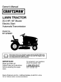
Owner's Manual
JCRRFTSMIIWI
LAWN TRACTOR
20.0 HP, 48" Mower
Electric Start
AutomaticTransmission
Model No.
917.272247
i]_
from
previouslyhas built
the engine,
read
This product
a low engines.
emission Before
engine you
whichstart
operates
differently
and understand
this Owner's Manual.
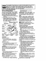
IMPORTANT:
Read and follow all
Safety Rules and Instructions
before operating this equipment.
For answers to your questions
about this product, Call:
1-800-659-5917
Sears Craftsman Help Line
5 am - 5 pm, Mon - Sat
Sears, Roebuck and Co., Hoffman Estates, IL 60179 U.S.A.
Visit our Craftsman website: www.sears.com/craftsman
Maintenance
.......................................
15
Service and Adjustments
.................... 19
Storage ...............................................
28
Troubleshooting
.................................
29
Repair Parts ........................................
34
Sears Service ......................
Back Cover
Warranty ...............................................
2
Safety Rules .........................................
3
Product Specifications
..........................
6
Assem bly/Pre-Ope ration ......................
7
Operation ..............................................
9
Maintenance
Schedule ......................
15
LIMITED WARRANTY
ON CRAFTSMAN
RIDING EQUIPMENT
For two (2) years from the date of purchase, if this Craftsman
Riding Equipment is
maintained,
lubricated and tuned up according to the instructions
in the owner's
manual, Sears will repair or replace free of charge any parts that are found to be
defective in material or workmanship
according to the guidelines
of coverage listed
below. Sears will also provide free labor for these applicable warranted parts for the
two full years. During the first 30 days of purchase, there will be no charges to service
the product at your home for issues covered by this warranty. (See exclusions below).
For your convenience,
IN HOME warranty service will still be available after the first 30
days of purchase, but a trip charge will apply. This charge will be waived if the Craftsman product is dropped off at an authorized
Sears location. For the nearest authorized
Sears location, please call 1-800-4-MY-HOME®.
This warranty applies only while this
product is within the United States.
This Warranty does not cover:
• Expendable
items which become worn during normal use, including but not limited
to blades, spark plugs, air cleaners, belts, and oil filters.
• Standard Maintenance
Servicing, oil changes,
or tune-ups
• Tire replacement
or repair caused by punctures from outside objects, such as nails,
thorns, stumps, or glass.
• Repairs necessary because of operator abuse, including but not limited to, damage
caused by towing objects beyond the capability of the riding equipment,
impacting
objects that bend the frame or crankshaft,
or over-speeding
the engine.
• Repairs necessary because of operator negligence,
including but not limited to,
electrical and mechanical
damage caused by improper storage, failure to use the
proper grade and amount of engine oil, failure to keep the deck clear of flammable
debris, or failure to maintain the equipment according to the instructions
contained in
the owner's manual.
• Engine (fuel system) cleaning or repairs caused by fuel determined
to be contaminated or oxidized (stale).
In general, fuel should be used within 30 days of its
purchase date.
• Normal deterioration
and wear of the exterior finishes, or product label replacement.
• Riding equipment
used for commercial
or rental purposes.
LIMITED WARRANTY
ON BATTERY
For ninety (90) days from date of purchase, if any battery included with this riding
equipment
proves defective in material or workmanship
and our testing determines the
battery will not hold a charge, Sears will replace the battery at no charge.
During the
first 30 days of purchase, there will be no charges to replace the battery at your HOME.
After the first 30 days, for your convenience,
IN-HOME warranty service will still be
available but a trip charge will apply. This charge will be waived if the Craftsman
product is dropped of at an authorized
Sears location. For the nearest authorized
Sears location, please call 1-800-4-MY-HOME®.
This battery
warranty
applies
only while this product
This warranty gives you specific
vary, from state to state.
Sears,
Roebuck
legal rights,
and Co.,Dept.817WA,
and you may also have other rights,
Hoffman
2
is within the United States.
Estates,
IL 60179
which
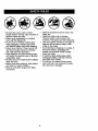
IMPORTANT: This cutting machine is capable of amputating hands and feet and
throwing objects. Failure to observe the following safety instructions could result in
serious injury or death.
• Do not mow in reverse unless absolutely
necessary. Always look down and
behind before and while backing.
• Be aware of the mower discharge
direction and do not point it at anyone.
Do not operate the mower without either
the entire grass catcher or the guard in
place.
• Slow down before turning.
• Never leave a running machine
unattended. Always turn off blades, set
parking brake, stop engine, and remove
keys before dismounting.
• Turn off blades when not mowing.
• Stop engine before removing grass
catcher or unclogging chute.
• Mow only in daylight or good artificial
light.
• Do not operate the machine while under
the influence of alcohol or drugs.
• Watch for traffic when operating near or
crossing roadways.
• Use extra care when loading or unloading the machine into a trailer or truck.
• Data indicates that operators, age 60
years and above, are involved in a large
percentage of riding mower-related
injuries. These operators should
evaluate their ability to operate the riding
mower safely enough to protect themselves and others from serious injury.
• Keep machine free of grass, leaves or
other debris build-up which can touch
hot exhaust / engine parts and burn. Do
not allow the mower deck to plow leaves
or other debris which can cause buildup to occur. Clean any oil or fuel
spillage before operating or storing the
machine. Allow machine to cool before
storage.
_II, WARNING:
In order to prevent
accidental starting when setting up,
transporting,
adjusting or making repairs,
always disconnect
spark plug wire and
place wire where it cannot contact spark
plug.
,_WARNING:
Do not coast down a hill
in neutral, you may lose control of the
tractor.
WARNING: Tow only the attachments that are recommended by and
comply with specifications of the manufacturer of your tractor. Use common
sense when towing. Operate only at the
lowest possible speed when on a slope.
Too heavy of a load, while on a slope, is
dangerous. Tires can lose traction with
the ground and cause you to lose control
of your tractor.
_KWARNING: Engine exhaust, some of
its constituents, and certain vehicle
components contain or emit chemicals
known to the State of California to cause
cancer and birth defects or other reproductive harm.
_ILWARNING: Battery posts, terminals
and related accessories contain lead
and lead compounds, chemicals known
to the State of California to cause cancer
and birth defects or other reproductive
harm. Wash hands after handling.
I. GENERAL
OPERATION
• Read, understand, and follow all
instructions in the manual and on the
•
•
•
•
I1.SLOPE
machine before starting.
Only allow responsible adults, who are
familiar with the instructions, to operate
the machine.
Clear the area of objects such as rocks,
toys, wire, etc., which could be picked
up and thrown by the blade.
Be sure the area is clear of other people
before mowing. Stop machine if anyone
enters the area.
Never carry passengers.
OPERATION
Slopes are a major factor related to loss-ofcontrol and tipover accidents, which can result in severe injury or death.
All slopes
require extra caution. If you cannot back up
the slope or if you feel uneasy on it, do not
mow it.
3
DO:
• Never carry children. They may fall off
and be seriously injured or interfere
with safe machine operation.
• Never allow children to operate the
machine.
• Use extra care when approaching blind
corners, shrubs, trees, or other objects
that may obscure vision.
• Mow up and down slopes, not across.
• Remove obstacles such as rocks, tree
limbs, etc.
• Watch for holes, ruts, or bumps. Uneven
terrain could overturn the machine. Tall
grass can hide obstacles.
• Use slow speed. Choose a low gear so
that you will not have to stop or shift
while on the slope.
• Follow the manufacturer's
recommendations for wheel weights or counterweights to improve stability.
• Use extra care with grass catchers or
other attachments.
These can change
the stability of the machine.
• Keep all movement on the slopes slow
and gradual.
Do not make sudden
changes in speed or direction.
• Avoid starting or stopping on a slope. If
tires lose traction,
disengage the blades
and proceed slowly straight down the
slope.
DO NOT:
IV. SERVICE
• Use extra care in handling gasoline
and other fuels. They are flammable
and vapors are explosive.
- Use only an approved container.
- Never remove gas cap or add fuel
with the engine running. Allow
engine to cool before refueling. Do
not smoke.
-Never refuel the machine indoors.
- Never store the machine or fuel
container inside where there is an
open flame, such as a water heater.
• Never run a machine inside a closed
area.
• Keep nuts and bolts, especially blade
attachment bolts, tight and keep
equipment
in good condition.
• Never tamper with safety devices.
Check their proper operation regularly.
• Keep machine free of grass, leaves, or
other debris build-up. Clean oil or fuel
spillage. Allow machine to cool before
storing.
• Stop and inspect the equipment
if you
strike an object. Repair, if necessary,
before restarting.
• Never make adjustments
or repairs
with the engine running.
• Grass catcher components
are subject
to wear, damage, and deterioration,
which could expose moving parts or
allow objects to be thrown.
Frequently
check components
and replace with
manufacturer's
recommended
parts,
when necessary.
• Mower blades are sharp and can cut.
Wrap the blade(s) or wear gloves, and
use extra caution when servicing them.
• Check brake operation frequently.
Adjust and service as required.
• Do not turn on slopes unless necessary,
and then, turn slowly and gradually
downhill, if possible.
• Do not mow near drop-offs, ditches, or
embankments.
The mower could
suddenly turn over if a wheel is over the
edge of a cliff or ditch, or if an edge
caves in.
• Do not
traction
• Do not
putting
• Do not
slopes.
mow on wet grass. Reduced
could cause sliding.
try to stabilize the machine by
your foot on the ground.
use grass catcher on steep
IlL CHILDREN
Tragic accidents can occur if the operator
is not alert to the presence of children.
Children are often attracted to the
machine and the mowing activity.
Never
assume that children will remain where
you last saw them.
• Keep children out of the mowing area
and under the watchful care of another
responsible
adult.
• Be alert and turn machine off if children
enter the area.
• Before and when backing, look behind
and down for small children.
4
• Be sure the area is clear of other
people before mowing. Stop machine if
anyone enters the area.
• Never carry passengers or children
even with the blades off.
• DO not mow in reverse unless absolutely necessary. Always look down
and behind before and while backing.
• Never carry children. They may fall off
and be seriously injured or interfere
with safe machine operation.
• Keep children out of the mowing area
and under the watchful care of another
responsible adult.
• Be alert and turn machine off if children
enter the area.
• Before and when backing, look behind
and down for small children.
• Mow up and down slopes (15 ° Max),
not across.
• Remove obstacles such as recks, tree
limbs, etc.
• Watch for holes, ruts, or bumps.
Uneven terrain could overturn the
machine. Tall grass can hide obstacles.
• Use slow speed. Choose a low gear so
that you will not have to stop or shift
while on the slope.
• Avoid starting or stopping on a slope. If
tires lose traction, disengage the
blades and proceed slowly straight
down the slope.
• If machine stops while going uphill,
disengage blades, shift into reverse
and back down slowly.
• Do not turn on slopes unless necessary, and then, turn slowly and gradually downhill, if possible.
5
PRODUCT
Please read and retain this manual. The
instructions will enable you to assemble
and maintain your tractor properly. Always
observe the "SAFETY RULES".
SPECIFICATIONS
Gasoline
4 Gallons
Capacity
and Type:
Unleaded
Regular
Oil Type
SAE 10W30
(above 32°F)
API-SF-SJ):
A Repair Agreement
is available on this
product. Contact your nearest Sears
store for details.
SAE 5W-30
(below 32°F)
Dil Capacity:
W/Filter:
W/O Filter:
Spark Plug:
_Gap: .030")
Champion
3round
REPAIR AGREEMENT
Speed
0 - 5.5
0 - 2.4
Front:
Rear:
14 PSI
10 PSI
Charging
System:
15 Amps
Battery:
@ 3600 RPM
Amp/Hr:
Min. CCA:
Case size:
Blade Bolt Torque:
RESPONSIBILITIES
• Read and observe the safety rules.
• Follow a regular schedule in maintaining, caring for and using your tractor.
• Follow the instructions under "Maintenance" and "Storage" sections of this
owner's manual.
AWARNING:
This tractor is equipped
with an internal combustion engine and
should not be used on or near any
unimproved forest-covered, brushcovered or grass-covered land unless the
engine's exhaust system is equipped with
a spark arrester meeting applicable local
or state laws (if any). If a spark arrester is
used, it should be maintained in effective
working order by the operator.
In the state of California the above is
required by law (Section 4442 of the
California Public Resources Code).
Other states may have similar laws.
Federal laws apply on federal lands. A
spark arrester for the muffler is available
through your nearest Sears service
center (See REPAIR PARTS section of
this manual).
RC12YC
(MPH):
Forward:
Reverse:
Tire Pressure:
CUSTOMER
4.5 Pints
4.0 Pints
28
230
U1R
45-55 Ft. Lbs.
CONGRATULATIONS
on your purchase
of a new tractor. It has been designed,
engineered and manufactured to give you
the best possible dependability and
performance.
Should you experience any problem you
cannot easily remedy, please contact a
Sears or other qualified service center.
We have competent, well-trained technicians and the proper tools to service or
repair this tractor.
Keys
(2) Keys
For Future Use
Video Cassette
Mower
Leveling
Slope Sheet
Bubble
Wrench
6
Level
Your new tractor has been assembled at the factory. Review the video cassette before
you begin.
When right or left hand is mentioned in
this manual, it means, from your point of
view, when you are in the operating position (seated behind the steering wheel).
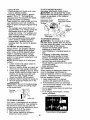
Adiostment
TO REMOVE TRACTOR FROM
CARTON
UNPACK
CARTON
Knob
1. Cut, from top to bottom, along lines on
all four corners of carton, and lay
panels flat.
2. Remove packing materials.
3. Remove protective materials from
tractor hood and grill.
IMPORTANT:
Check for and remove any
staples in skid that may puncture tires
where tractor is to roll off skid.
NOTE: You may now roll or drive your
tractor off the skid. Follow the appropriate
instruction below to remove the tractor
from the skid.
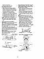
TO ROLLTRACTOR
OFF SKID (See
Operation section for location and
function of controls)
1. Press lift Fever plunger and raise
attachment lift lever to its highest
position.
2. Release parking brake by depressing
brake pedal.
3. Place freewheel control in "transmission disengaged" position (See "TO
TRANSPORT' in the Operation
section of this manual).
4. Roll tractor forward off skid.
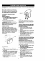
CHECK BA'n'ERY
1. Lift hood to raised position.
NOTE: If this battery is put into service
after month and year indicated on label
(label located between terminals) charge
battery for minimum of one hour at 6-10
amps. (See "BATTERY" in Maintenance
section of this manual for charging
instructions).
/"°"
,,.."'"
.-'°'
Label
TO DRIVE TRACTOR
OFF SKID (See
Operation
section for location
and
function
of controls)
A WARNING:
Before starting, read,
understand
and follow all instructions
in
the Operation section of this manual. Be
sure tractor is in a well-ventilated
area. Be
sure the area in front of tractor is clear of
ADJUST
other people and objects.
1. Be sure all the above assembly steps
have been completed.
2. Check engine oil level and fill fuel
tank with gasoline.
3. Place freewheel control in "transmission engaged" position. (See "TO
TRANSPORT'
in the Operation
section of this manual).
4. Sit on seat in operating position,
depress brake pedal and set the
parking brake.
5. Press lift lever plunger and raise
attachment lift lever to its highest
position.
SEAT
1. Raise seat and loosen adjustment
knob.
2.
Lower seat into operating
sit in seat.
position
and
3.
Slide seat until a comfortable
position
is reached which allows you to press
clutch/brake
pedal all the way down.
4. Get off seat without moving its
adjusted
position.
5. Raise seat and tighten adjustment
knob securely.
7
,/'CHECKLIST
6. Start the engine. After engine has
started, move throttle control to idle
position.
7. Release parking brake.
8. Slowly depress forward drive pedal
and drive tractor off skid.
9. Apply brake to stop tractor and set
parking brake.
10.Turn ignition key to "STOP" position.
Continue with the instructions that follow.
CHECK
TIRE
Before you operate your new tractor, we
wish to assure that you receive the best
performance and satisfaction from this
Quality Product.
Please review the following checklist:
,I All assembly instructions have been
completed.
,/No remaining loose parts in carton.
,/Battery
is properly prepared and
charged.
(Minimum 1 hour at 6 amps).
,/Seat
is adjusted comfortably and
tightened securely.
•/ All tires are properly inflated. (For
shipping purposes, the tires were
overinflated at the factory).
•/ Be sure mower deck is properly leveled
side-to-side/front-to-rear
for best cutting
results. (Tires must be properly inflated
for leveling).
,/Check
mower and drive belts. Be sure
PRESSURE
The tires on your tractor were overinflated
at the factory for shipping purposes.
Correct tire pressure is important for best
cutting performance.
• Reduce tire pressure to PSI shown in
"PRODUCT
SPECIFICATIONS"
section
of this manual.
CHECK DECK LEVELNESS
For best cutting results, mower housing
should be properly leveled. See '_O
LEVEL MOWER HOUSING" in the
Service and Adjustments section of this
manual.
they are routed properly around pulleys
and inside all belt keepers.
,/Check
wiring. See that all connections
are still secure and wires are properly
clamped.
,/Before driving tractor, be sure freewheel control is in '_transmission
engaged" position (see 'qo Transport"
in the Operation section of this
manual).
While learning how to use your tractor,
pay extra attention to the following
important items:
,/Engine
oil is at proper level.
,/Fuel tank is filled with fresh, clean,
regular unleaded
gasoline.
,/Become
familiar with all controls, their
location and function.
Operate them
before you start the engine.
,I Be sure brake system is in safe
operating
condition.
,/It is important to purge the transmission
before operating your tractor for the first
time. Follow proper starting and
transmission
purging instructions
(See
"TO START ENGINE" and "PURGE
TRANSMISSION"
in the Operation
section of this manual).
CHECK FOR PROPER POSITION OF
ALL BELTS
See the figures that are shown for
replacing motion and mower blade drive
belts in the Service and Adjustments
section of this manual. Verify that the
belts are routed correctly.
CHECK
BRAKE SYSTEM
After you learn how to operate your
tractor, check to see that the brake is
properly adjusted.
See 'qO ADJUST
BRAKE" in the Service and Adjustments
section of this manual.
8
These symbols may appear on your tractor or in literature supplied with the product.
Learn and understand their meaning.
R
N
H
L
REVERSE
NEUTRAL
HIGH
LOW
ENGINE OFF
LIGHTS ON
OVER TEMP
LIGHT
FUEL
ATTACHMENT
CLUTCH ENGAGF.O
ENGINE ON
OIL PRESSURS
ATTACHMENT
CLUTCH DISENGAGED
FREE WHEEL
(Automatic Models only)
&
result in death, serious injury
and/or property damage.
CHOKE
ENGINE START
BATI]ERY
&
&
&
FAST
PARKING BRAKE
REVERSE
DANGER, KEEP HANDS
AND FEET AWAY
FORWARD
SLOW
IGNITION
PARKING BRAKE
LOCKED
MOWER HEIGHT
KEEP AREA CLEAR
PARKING BRAKE
UNLOCKED
MOWER UFT
SLOPE HAZARDS
(SEE SAFETY RULES SECTION)
DANGER indicates a hazard which, if not avoided,
will result in death or serious injury.
WARNING indicates a hazard which, if not avoided,
could result in death or serious injury.
CAUTION indicatesa hazard which, if Rot avoided,
might result in minor or moderate injury.
CAUTION when used without the alert symboT,
indicates a situation that could result in damage
to the tractor and/or engine.
Failure to follow instructions
could result in serious injury or
death. The safety alert symbol
is used to identify safety information about hazards which can
I',,I
HOT SURFACES indicatesa hazard which,
.,_,_l,,,. if not avoided,could result in death, serious injury
and/or property damage.
.a_
FIRE indicates a hazard which, if not avoided,
could result in death, serious injury and/or
property damage.
9
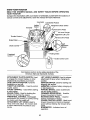
KNOW
READ
YOUR
YOUR
TRACTOR
THIS OWNER'S
TRACTOR
MANUAL
AND
SAFETY
RULES
BEFORE
OPERATING
Compare the illustrations with your tractor to familiarize yourself with the locations of
various controls and adjustments. Save this manual for future reference.
Hourmeter
Ammeter
Ignition
Switch
Light Switch Position
Attachment Clutch Switch
Drive Pedal
Attachment
Throttle
ger
Lift Lever
.Reverse Drive Pedal
Brake
Freewheel
Cruise Control Lever
Our tractors conform to the safety standards of the
American
National Standards
Institute.
ATTACHMENT
CLUTCH SWITCH: Used
to engage the mower blades, or other
attachments mounted to your tractor.
LIGHT SWITCH POSITION: Turns the
headlights on and off.
THROTTLE
CONTROL
- Used to control
engine speed.
CHOKE CONTROL
- Used when starting
a cold engine.
BRAKE PEDAL: Used for braking the
tractor and starting the engine.
FREEWHEEL
CONTROL:
Disengages
transmission for pushing or slowly towing
the tractor with the engine off.
ATTACHMENT
LIFT LEVER: Used to
raise, lower and adjust the mower deck
or other attachments
mounted to your
tractor.
LIFT LEVER PLUNGER:
Used to release
attachment
lift lever when changing its
position.
IGNITION SWITCH: Used for starting and
stopping the engine.
AMMETER:
Indicates battery charging (+)
or discharging (-).
PARKING BRAKE: Locks clutch/brake
into the brake position.
FORWARD DRIVE PEDAL - Used for
forward movement of tractor.
REVERSE DRIVE PEDAL - Used for
reverse movement of tractor.
CRUISE CONTROL
LEVER - Used to set
forward movement of tractor at desired
speed without holding the forward drive
pedal.
HOURMETER
- Indicates hours of
operation.
10
The operation of any tractor can result in foreign objects thrown into the
eyes, which can result in severe eye damage. Always wear safety
glasses or eye shields while operating your tractor or performing any
adjustments or repairs. We recommend standard safety glasses or a
wide vision safety mask worn over spectacles.
HOW TO USE YOUR TRACTOR
when leaving tractor to prevent
unauthorized use.
• Never use choke to stop engine.
IMPORTANT: Leaving the ignition switch
in any position other than "STOP" will
cause the battery to discharge and go
dead.
NOTE" Under certain conditions when
tractor is standing idle with the engine
running, hot engine exhaust gases may
cause "browning" of grass. To eliminate
this possibility, always stop engine when
stopping tractor on grass areas.
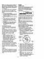
TO SET PARKING
BRAKE
Your tractor is equipped with an operator
presence sensing switch. When engine
is running, any attempt by the operator to
leave the seat without first setting the
parking brake will shut off the engine.
1. Depress brake pedal all the way down
and hold.
2. Pull parking brake lever up and
release pressure from brake pedal.
Pedal should remain in brake position. Make sure parking brake will
hold tractor secure.
Attachment Clutch Switch
Push-in to
Pull Out To "Engage"
"Disen(
_,CAUTION:
Always stop tractor
completely, as described above, before
leaving the operator's position.
Ignition Key
THRO'n'LE
Choke
"Brake'
Position
Brak
"Drive"
Position
Always operate engine at full throttle.
• Operating engine at less than full
throttle reduces the battery charging
rate.
• Full throttle offers the best bagging and
mower performance.
TO USE CHOKE CONTROL
Reverse
Drive
"Disehgaged"
Position
Brake C L_ise
"Engaged"
Control
_osmon
Lever
STOPPING
MOWER
BLADES
CONTROL
-
Use choke control whenever you are
starting a cold engine. Do not use to start
a warm engine.
• To engage choke control, pull knob out.
Slowly push knob in to disengage.
TO MOVE FORWARD
AND BACKWARD
The direction and speed of movement is
controlled by the forward and reverse drive
pedals.
1. Start tractor and release parking brake.
2. Slowly depress forward or reverse
drive pedal to begin movement.
Ground speed increases the further
down the pedal is depressed.
TO USE CRUISE CONTROL
• To stop mower blades, push attachment clutch switch in to disengaged
position.
GROUND DRIVE • To stop ground drive, depress clutch/
brake pedal all the way down.
• Move motion control lever to neutral (N)
position.
IMPORTANT: The motion control lever
The cruise control feature can be used for
forward travel only.
1. With forward drive pedal depressed
to
desired speed, move cruise control
lever forward to "SET' position and
hold while lifting your foot off the
pedal, then release the cruise control
lever.
To disengage the cruise control, pull the
lever backward to "OFF" position, or fully
depress the brake pedal.
TO ADJUST MOWER CUTTING HEIGHT
does not return to neutral (N) position
when the clutch/brake
pedal is depressed.
ENGINE • Move throttle control between half and
full speed (fast) position.
NOTE: Failure to move throttle control
between half and full speed (fast)
position, before stopping, may cause
engine to "backfire".
• Turn ignition key to "STOP" position
and remove key. Always remove key
11
The position of the attachment
determines the cutting height.
lift lever
TO STOP MOWER BLADES disengage
attachment
clutch control•
_,CAUTION:
Do not operate the mower
without either the entire grass catcher, on
mowers so equipped, or the deflector
shield in place.
Attachment Lift
Attachment Clutch
Lever High Position
Switch Pull Out To
• Grasp lift lever.
• Press plunger with thumb and move
lever to desired position•
The cutting height range is approximately 1-1/2 to 4". The heights are
measured from the ground to the blade
tip with the engine not running.
These heights are approximate
and may
vary depending
upon soil conditions,
height of grass and types of grass being
mowed.
• The average lawn should be cut to
approximately
2-1/2 inches during the
cool season and to over 3 inches
during hot months.
For healthier and
better looking lawns, mow often and
after moderate growth.
• For best cutting performance,
grass
over 6 inches in height should be
mowed twice. Make the first cut
relatively high; the second to desired
height.
TO ADJUST GAUGE WHEELS
"Engage"
,i
TO OPERATE
ON HILLS
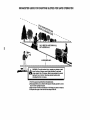
_WARNING:
Do not drive up or down
hills with slopes greater than 15 ° and do
not drive across any slope. Use the slope
guide at the back of this manual.
• Choose the slowest speed before
starting up or down hills.
• Avoid stopping or changing speed on
hills.
• If stopping is absolutely necessary,
push brake pedal quickly to brake
position and engage parking brake.
• To restart movement, slowly release
parking brake and brake pedal.
• Slowly depress appropriate drive pedal
to slowest setting.
• Make all turns slowly•
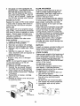
TO TRANSPORT
When pushing or towing your tractor, be
sure to disengage transmission
by
placing freewheel
control in freewheeling
position.
Freewheel control is located at
the rear drawbar of tractor.
1.
Raise attachment
lift to highest
position with attachment
lift control•
2. Pull freewheel control out and down
into the slot and release so it is held in
the disengaged
position•
• Do not push or tow tractor at more than
two (2) MPH.
• To re-engage transmission,
reverse
above procedure•
Transmission
Engaged
J
Clevis Pin
MOWER
Your tractor is equipped with an operator
presence sensing switch. Any attempt by
the operator to leave the seat with the
engine running and the attachment
clutch
engaged will shut off the engine.
1. Select desired height of cut.
2. Start mower blades by engaging
attachment
clutch control•
Low
Position
Push In To
"Disengage _"_----_ _
Retainer
Spring
• .
"
.f_
Gauge wheels are properly adjusted
when they are slightly off the ground
when mower is at the desired cutting
height in operating position. Gauge
wheels then keep the deck in proper
position to help prevent scalping in most
terrain conditions.
NOTE: Be sure tractor is on a flat level
surface.
1. Lower mower and adjust mower to
desired cutting height.
2. Remove retainer spring and clevis pin
which secure each gauge wheel bar.
3. Lower gauge wheels to ground. Raise
gauge wheels slightly to align holes in
bracket and gauge wheel bar and
insert clevis pin. Gauge wheels
should be slightly off the ground.
4. Replace retainer spring into clevis pin.
5. Be sure all gauge wheels are in the
same setting.
IMPORTANT:
Be sure to readjust gauge
wheels if you change the cutting height
of the mower deck.
TO OPERATE
_
Transmission
12
Disengaged
NOTE: To protect hood from damage
when transporting your tractor on a truck
or a trailer, be sure hood is closed and
secured to tractor. Use an appropriate
means of tying hood to tractor (rope, cord,
etc.).
TOWING CARTS AND OTHER ATTACHMENTS
Tow only the attachments that are
recommended by and comply with
specifications of the manufacturer of your
tractor. Use common sense when towing.
Too heavy of a load, while on a slope, is
dangerous. Tires can lose traction with
the ground and cause you to lose control
of your tractor.
BEFORE STARTING THE ENGINE
CHECK ENGINE OIL LEVEL
The engine in your tractor has been
shipped, from the factory, already filled
with summer weight oil.
1. Check engine oil with tractor on level
ground.
2. Unthread and remove oil fill cap/
dipstick; wipe oil off. Reinsert the
dipstick into the tube and rest oil fill
cap on the tube. Do not thread the
cap onto the tube. Remove and read
oil level. If necessary, add oil until
"FULL" mark on dipstick is reached.
Do not overfill.
• For cold weather operation you should
change oil for easier starting (See the oil
viscosity chart in the Maintenance
section of this manual).
• To change engine oil, see the Maintenance section in this manual.
ADD GASOLINE
• Fill fuel tank to bottom of tank filler
neck. Do not overfill. Use fresh, clean,
regular unleaded gasoline with a
minimum of 87 octane. (Use of leaded
gasoline will increase carbon and lead
oxide deposits and reduce valve life).
Do not mix oil with gasoline. Purchase
fuel in quantities that can be used
within 30 days to assure fuel freshness.
•,CAUTION:
Wipe off any spilled oil or
fuel. Do not store, spill or use gasoline
near an open flame.
IMPORTANT:
When operating in temperatures below 32°F(0°C),
use fresh,
clean winter grade gasoline to help
insure good cold weather starting.
CAUTION:
Alcohol blended fuels (called
gasohol or using ethanol or methanol)
can attract moisture which leads to
separation and formation of acids during
storage. Acidic gas can damage the fuel
system of an engine while in storage.
To avoid engine problems, the fuel
system should be emptied before storage
of 30 days or longer. Drain the gas tank,
start the engine and let it run until the fuel
lines and carburetor are empty. Use fresh
fuel next season. See Storage Instructions for additional information.
Never use engine or carburetor cleaner
products in the fuel tank or permanent
damage may occur.
TO START
ENGINE
When starting the engine for the first time
or if the engine has run out of fuel, it will
take extra cranking time to move fuel from
the tank to the engine.
1. Be sure freewheel control is in the
transmission engaged position.
2. Sit on seat in operating position,
depress brake pedal and set parking
brake.
3. Move attachment clutch to disengaged position.
4. Move throttle control to fast position
5. Pull choke control out for a cold
engine start attempt. For a warm
engine start attempt the choke control
may not be needed.
NOTE: Before starting, read the warm and
cold starting procedures
below.
6. Insert key into ignition and turn key
clockwise to start position and release
key as soon as engine starts. Do not
run starter continuously for more than
fifteen seconds per minute. If the
engine does not start after several
attempts, push choke control in, wait a
few minutes and try again. If engine
still does not start, pull the choke
control out and retry.
WARM WEATHER STARTING (50 ° F and
above)
7. When engine starts, slowly push
choke control in until the engine
begins to run smoothly. If the engine
starts to run roughly, pull the choke
control out slightly for a few seconds
and then continue to push the control
in slowly.
• The attachments
and ground drive can
now be used. If the engine does not
accept the load, restart the engine and
allow it to warm up for one minute
13
using the choke as described above.
COLDWEATHER
STARTING (50 F and
below)
7. When engine starts, slowly push
choke control in until the engine
begins to run smoothly. Continue to
push the choke control in small steps
allowing the engine to accept small
changes in speed and load, until the
choke control is fully in.
If the engine starts to run roughly, pull
the choke
control out slightly for a few
seconds and then continue to push the
control in slowly. This may require an
engine warm-up period from several
seconds to several minutes, depending
on the temperature.
AUTOMATIC TRANSMISSION
WARM UP
Before driving the unit in cold weather, the
transmission
should be warmed up as
follows:
1. Be sure the tractor is on level ground.
2. Release the parking brake and let the
brake slowly return to operating
position.
3. Allow one minute for transmission
to
warm up. This can be done during the
engine warm up period.
• The attachments
can be used during the
engine warm-up period after the
transmission
has been warmed up and
may require the choke control be pulled
out slightly.
NOTE" If at a high altitude (above 3000
feet) or in cold temperatures
(below 32 F)
the carburetor fuel mixture may need to be
adjusted for best engine performance.
(See 'q'O ADJUST CARBURETOR"
in the
Service and Adjustments
section of this
manual).
PURGE TRANSMISSION
_il,CAUTION"
Never engage or disengage
freewheel lever while the engine is running.
To ensure proper operation and performance, it is recommended
that the transmission be purged before operating tractor for
the first time. This procedure will remove any
trapped air inside the transmission which
may have developed during shipping of
your tractor.
IMPORTANT:
Should your transmission
require removal for service or replacement,
it should be purged after reinstallation
before operating the tractor.
1. Place tractor safely on level surface
with engine off and parking brake set.
2. Disengage
transmission
by placing
freewheel
control in disengaged
position (See "TO TRANSPORT"
in this
section of manual).
3. Sitting in the tractor seat, start engine.
After the engine is running, move
throttle control to slow position.
Disengage
parking brake.
4. Depress forward drive pedal to full
forward position and hold for five (5)
seconds and release pedal. Depress
reverse drive pedal to full reverse
position and hold for five (5) seconds
and release pedal. Repeat this
procedure three (3) times.
NOTE" During this step there will be no
movement of drive wheels. The air is being
removed from hydraulic drive system.
5.
6.
Shut off engine and set parking brake.
Engage transmission
by placing
freewheel
control in "transmission
engaged" position (See "TO TRANSPORT' in this section of manual).
7. Sitting in the tractor seat, start engine.
After the engine is running, move
throttle control to half (1/2)speed.
Disengage
parking brake.
8. Drive tractor forward for approximately
five feet then backwards for five feet.
Repeat this driving procedure three
times.
Your transmission
is now purged and
ready for normal operation.
MOWING
TIPS
• Mower should be properly leveled for
best mowing performance.
See 'q'O
LEVEL MOWER HOUSING"
in the
Service and Adjustments
section of this
manual.
• The left hand side of mower should be
used for trimming.
• Drive so that clippings are discharged
onto the area that has already been
cut. Have the cut area to the right of the
tractor.
This will result in a more even
distribution
of clippings and more
uniform cutting.
• When mowing large areas, start by
turning to the right so that clippings will
discharge away from shrubs, fences,
driveways, etc. After one or two
rounds, mow in the opposite direction
making left hand turns until finished.
f
• If grass is extremely tall, it should be
mowed twice to reduce load and
possible fire hazard from dried clippings. Make first cut relatively high; the
second to the desired height.
• Do not mow grass when it is wet. Wet
grass will plug mower and leave
undesirable
clumps.
Allow grass to dry
before mowing.
• Always operate engine at full throttle
when mowing to assure better mowing
performance
and proper discharge of
material.
Regulate ground speed by
selecting a low enough gear to give the
mower cutting performance
as well as
the quality of cut desired.
• When operating attachments,
select a
ground speed that will suit the terrain
and give best performance
of the
14 attachment being used.
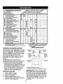
MA,NTENANC
SCR DU'
Check
Operation
Check Brake
Tire Pressure
_
""
_V'
Check Operator Presence and
T
Interlock
Check forSystems
Loose Fasteners
_VW
II_s
V #
Lubrication Chart
T
A
g
Check
Battery Level
Sharpen/Replace
Mower Blades
Clean Battery and Terminals
i3
Check Transaxle Cooling
(1_
I_ /
CheCk V-Belts
CheckEr_r_ O, L_
Change
l/
V'
Erlgine Oil (with oil filter)
VWl,=
NE lifter)Clean
ChangeAirEngine
Filter Oil (withOutOil
G
EN
_i
V w
_
Clean Air Screen
Inspect Muffler/Spark An.ester
Replace Oil Filter (If equipped)
_.=
Clean Engine Cooling Fins
_
Replace Spark Plug
I1_
2
(1_
Replace Air Filter Paper Cartridge
Replace Fuel Filter
I##
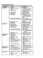
1 - Change more often when operating under a heavy load or
in high ambient temperatures.
2 - Service more often when operating in dirty or dusty conditions.
GENERAL
LUBRICATION
RECOMMENDATIONS
The warranty on this tractor does not cover
items that have been subjected to operator
abuse or negligence. To receive full value
from the warranty, operator must maintain
tractor as instructed in this manual.
Some adjustments will need to be made
periodically to properly maintain your
tractor.
All adjustments in the Service and
Adjustments section of this manual should
be checked at least once each season.
1.
2.
3.
4.
5.
EACH
CHART
_) Spindle
Zerk
(_ Spindle
Zerk
(D Front
Wheel
Bearing
Zerk
._
Wheel
Bearing
Zerk
Engine
_ Mandrel
Zerks
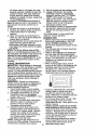
• Once a year you should replace the
spark plug, clean or replace air filter, and
check blades and belts for wear. A new
spark plug and clean air filter assure
proper air-fuel mixture and help your
engine run better and last longer.
BEFORE
3 - Replace blades more often when mowing in sandy soil.
4 - Not required if equipped with maintenance-free battery.
5 - Tighten front axle pivot bolt to 35 ft.-_bs, maximum.
Do not overtighten.
i
• General Purpose Grease
(_ Refer to Maintenance "ENGINE" Section
IMPORTANT:
Do not oil or grease the
pivot points which have special nylon
bear-ings. Viscous lubricants will attract
dust and dirt that will shorten the life of
the self-lubricating bearings. If you feel
they must be lubricated, use only a dry,
powdered graphite type lubricant
sparingly.
USE
Check engine oil level.
Check brake operation.
Check tire pressure.
Check operator presence and
interlock systems for proper operation.
Check for loose fasteners.
15
TRACTOR
IMPORTANT:
To ensure proper assembly,
center hole in blade must align with star
on mandrel assembly.
4. Reassemble blade bolt tighten bolt
securely (45-55 Ft. Lbs. torque).
IMPORTANT:
Blade bolt is grade 8 heat
treated.
Mandrel
Trailing
Assembly
Always observe safety rules when
performing
any maintenance.
BRAKE OPERATION
If tractor requires more than six (6) feet
stopping distance at high speed in
highest gear, then brake must be adjusted. (See "TO ADJUST BRAKE" in the
Service and Adjustments
section of this
manual).
TIRES
Edge
B,odeBo,t
• Maintain proper air pressure in all tires
(See "PRODUCT
SPECIFICATIONS"
section of this manual).
• Keep tires free of gasoline, oil, or insect
control chemicals which can harm
rubber.
• Avoid stumps, stones, deep ruts, sharp
objects and other hazards that may
cause tire damage.
NOTE: To seal tire punctures and prevent
flat tires due to slow leaks, tire sealant
may be purchased
from your local parts
dealer. Tire sealant also prevents tire dry
rot and corrosion.
OPERATOR
PRESENCE
SYSTEM
Center Hole
TO SHARPEN
Care should be taken to keep the blade
balanced.
An unbalanced blade will
cause excessive vibration and eventual
damage to mower and engine.
• The blade can be sharpened with a file
or on a grinding wheel. Do not attempt
to sharpen while on the mower.
• To check blade balance, you will need
a 5/8" diameter steel bolt, pin, or a cone
balancer. (When using a cone balancer, follow the instructions supplied
with balancer.)
NOTE:
Do not use a nail for balancing
blade. The lobes of the center hole may
appear to be centered, but are not.
• Slide blade on to an unthreaded
disengaged
position.
• When the engine is running, any
attempt by the operator to leave the
seat without first setting the parking
brake should shut off the engine.
• When the engine is running and the
attachment clutch is engaged, any
attempt by the operator to leave the
seat should shut off the engine.
• The attachment
clutch should never
portion of the steel bolt or pin and hold
the bolt or pin parallel with the ground.
If blade is balanced, it should remain in
a horizontal position.
If either end of
the blade moves downward, sharpen
the heavy end until the blade is
balanced.
Center Hole
is in the
Blade
5/8" Bolt
or Pin
For best results mower blades must be
kept sharp. Replace bent or damaged
blades.
BLADE
BLADE
NOTE: We do not recommend sharpening blade - but if you do, be sure the
blade is balanced.
Be sure that operator presence and
interlock systems are working properly. If
your tractor does not function as described below, repair the problem
immediately.
• The engine should not start unless the
brake pedal is fully depressed
and
attachment clutch control is in the
operate unless the operator
seat.
BLADE CARE
L.j
BATTERY
REMOVAL
Your tractor has a battery charging system
which is sufficient for normal use. How-
1. Raise mower to highest position to
allow access to blades.
2. Remove blade bolt.
3. Install new or resharpened
blade with
trailing edge up towards deck as
shown.
ever, periodic charging of the battery with
an automotive charger will extend its life.
• Keep battery and terminals clean.
• Keep battery bolts tight.
• Keep small vent holes open.
• Recharge at 6-10 amperes for 1 hour.
16
NOTE: The original equipment
battery on
your tractor is maintenance
free. Do not
attempt to open or remove caps or covers.
Adding or checking level of electrolyte is
not necessary.
TO CLEAN BA'I-I'ERY
AND TERMINALS
Corrosion and dirt on the battery and
terminals can cause the battery to "leak"
power.
1. Remove terminal guard.
2. Disconnect BLACK battery cable first
then RED battery cable and remove
battery from tractor.
3. Rinse the battery with plain water and
dry.
4. Clean terminals and battery cable
ends with wire brush until bright.
5. Coat terminals with grease or petroleum jelly.
6. Reinstall battery (See "REPLACING
BATTERY" in the SERVICE AND
ADJUSTMENTS
section of this
manual).
TRANSAXLE
ENGINE
LUBRICATION
Only use high quality detergent oil rated
with API service classification SF-SJ.
Select the oil's SAE viscosity grade
according to your expected operating
temperature.
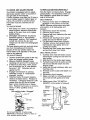
SAE VISCOSITY
._
.20
TEMPERATURE
TO CHANGE
ENGINE
OIL
Determine temperature
range expected
before oil change.
All oil must meet API
service classification SF-SJ.
• Be sure tractor is on level surface.
• Oil will drain more freely when warm.
• Catch oil in a suitable container.
COOLING
1. Remove oil fill cap/dipstick.
Be careful
not to allow dirt to enter the engine
when changing oil.
2. Remove yellow cap from end of drain
valve and install the drain tube onto
the fitting.
Oil Drain Valve
• Inspect cooling fan to be sure fan
blades are intact and clean.
Closed and _
Locked ___1
• Inspect cooling fins for dirt, grass
clippings and other materials. To
prevent damage to seals, do not use
compressed air or high pressure
sprayer to clean cooling fins.
Position
Yellow
PUMP FLUID
Cap _
The transaxle was sealed at the factory
and fluid maintenance
is not required for
the life of the transaxle.
Should the
3.
transaxle ever leak or require servicing,
contact a sears or other qualified service
center.
4.
5.
V-BELTS
Check V-belts for deterioration
10
20
BEFORE NEXT OIL CHANGE
Change the oil after every 50 hours of
operation or at least once a year if the
tractor is not used for 50 hours in one
year.
Check the crankcase oil level before
starting the engine and after each eight
(8) hours of operation.
The transmission fan and cooling fins
should be kept clean to assure proper
cooling.
Do not attempt to clean fan or transmission while engine is running or while the
transmission is hot. To prevent possible
damage to seals, do not use high
pressure water or steam to clean
transaxle.
TRANSAXLE
.10
0
RANGE _rrlCIPATED
GRADES
and wear
6.
after 100 hours of operation and replace
if necessary. The belts are not adjustable.
Replace belts if they begin to slip from
wear.
7.
17
I _'_
__°
_._ _, , -_r-,._-,_
_
._
Tube
Drain
Unlock drain valve by pushing inward
slightly and turning counterclockwise.
To open, pull out on the drain valve.
After oil has drained completely,
close
and lock the drain valve by pushing
inward and turning clockwise until the
pin is in the locked position as shown.
Remove the drain tube and replace
the cap onto to the end of the drain
valve.
Refill engine with oil through oil fill
dipstick tube. Pour slowly. Do not
overfill. For approximate
capacity see
"PRODUCT SPECIFICATIONS"
section of this manual.
8. Use gaugeon oil fill cap/dipstickfor
checkinglevel. Insertdipstickinto the
tube and restthe oil fill cap on the
tube. Do not threadthe cap onto the
tubewhen taking reading. Keepoil
at "FULL"line on dipstick. Tightencap
onto the tube securelywhen finished.
ENGINE
OIL FILTER
Replace the engine oil filter every season
or every other oil change if the tractor is
used more than 100 hours in one year.
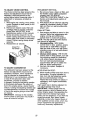
AIR FILTER
Your engine will not run properly using a
dirty air filter. Clean the foam pre-cleaner
after every 25 hours of operation or every
season. Service paper cartridge every
100 hours of operation or every season,
whichever occurs first.
Service air cleaner more often under
dusty conditions.
1. Loosen knob and remove cover.
TO SERVICE PRE-CLEANER
2. Slide foam pre-cleaner off cartridge.
3. Wash it in liquid detergent and water.
4. Squeeze it dry in a clean cloth. Allow
it to dry.
5. Saturate it in engine oil. Wrap it in
clean, absorbent cloth and squeeze to
remove excess oil.
TO SERVICE CARTRIDGE
• Replace a dirty, bent, or damaged
cartridge.
NOTE: Do not wash the paper cartridge
or use pressurized
air, as this will
damage the cartridge.
6. Remove nut and cartridge plate.
7. Reinstall the pre-cleaner
(cleaned
and oiled) over the paper cartridge.
8. Check rubber seal for damage and
proper position around stud. Replace
if necessary.
9. Reassemble
air cleaner, cartridge
plate, and nut.
10.Reinstall
air cleaner cover and secure
by tightening
knob.
Cartridge
Cartridge
"_.
_'ll_.,_ )-_j
CLEAN AIR SCREEN
Air screen must be kept free of dirt and
chaff to prevent engine damage from
overheating. Clean with a wire brush or
compressed air to remove dirt and
stubborn dried gum fibers.
CLEAN AIR INTAKE/COOLING AREAS
To insure proper cooling, make sure the
grass screen, cooling fins, and other
external surfaces of the engine are kept
clean at all times.
Every 100 hours of operation (more often
under extremely dusty, dirty conditions),
remove the blower housing and other
cooling shrouds. Clean the cooling fins
and external surfaces as necessary. Make
sure the cooling shrouds are reinstalled.
NOTE: Operating the engine with a
blocked grass screen, dirty or plugged
cooling fins, and/or cooling shrouds
removed will cause engine damage due
to overheating.
MUFFLER
Inspect and replace corroded muffler and
spark arrester (if equipped) as it could
create a fire hazard and/or damage.
SPARK
Replace spark plug(s) at the beginning of
each mowing season or after every 100
hours of operation, whichever occurs first.
Spark plug type and gap setting are
shown in "PRODUCT
SPECIFICATIONS"
section of this manual.
IN-LINE
,no
_Nut
FUEL FILTER
The fuel filter should be replaced once
each season. If fuel filter becomes
clogged, obstructing fuel flow to carburetor, replacement is required.
1. With engine cool, remove filter and
plug fuel line sections.
2. Place new fuel filter in position in fuel
line with arrow pointing towards
carbu retor.
3. Be sure there are no fuel line leaks
and clamps are properly positioned.
4. Immediately wipe up any spilled
gasoline.
P,a,e
_i_'_ri!_
PLUG(S)
Clamp
'F
Rubber
:ea
Fuel Filter_
Pre-Cleaner
18
CLEANING
We do not recommend
using a garden
hose to clean your tractor unless the
electrical system, muffler, air filter and
carburetor are covered to keep water out.
Water in engine can result in a shortened
engine life.
• Clean engine, battery, seat, finish, etc.
of all foreign matter.
• Keep finished surfaces and wheels free
of all gasoline, oil, etc.
• Protect painted surfaces with automotive type wax.
WARNING: TO AVOID SERIOUS INJURY, BEFORE PERFORMING
ANY
SERVICE OR ADJUSTMENTS:
1. Depress brake pedal fully and set parking brake.
2. Place attachment clutch in "DISENGAGED"
position.
3. Turn ignition key "STOP" and remove key.
4. Make sure the blades and all moving parts have completely stopped.
5. Disconnect spark plug wire from spark plug and place wire where it cannot
come in contact with plug.
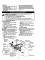
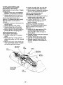
TO REMOVE
MOWER
1. Place attachment clutch in "DISENGAGED" position.
2. If equipped, turn height adjustment
knob to lowest setting.
3. Lower mower to its lowest position.
4. Disengage belt tension rod from lock
bracket.
CAUTION:
Rod is spring loaded. Have
a tight grip on rod and release slowly.
5. Remove retainer spring holding antiswaybar to chassis bracket and
disengage anti-sway bar from bracket.
6. Remove four retainer springs from
front plate assembly and remove
plate.
7. Remove retainer springs from
suspension arms at deck and disengage arms from deck.
Lock Bracket
Belt Tension
Front
Rod
Mower
(Disengaged_,;.
Position)
'_
8.
Raise attachment lift to its highest
position.
9. Slide mower forward and remove belt
from electric clutch pulley.
10.Slide mower out from under right side
of tractor.
TO INSTALL MOWER
Be sure tractor is on level surface and mower
suspension arms are raised with attachment
lift control. Engage parking brake.
1. Swing anti-sway bar to left side of
mower deck.
2. Slide mower under tractor with
deflector shield to right side of tractor.
IMPORTANT:
Check belt for proper
routing in all mower pulley grooves.
Electric
Clutch Pulley
Double Loop
Retainer Springs
Front Plate
Assembly
Chassis
Bracket
Single Loop
Retainer Springs
Spring
,ged Pins
AntiBar
USE PLIERS
_\
FOR
Suspension
Arms Double Loop
Retainer Springs
(Outward pointing
deck pins)
Front Mower
Bracket
Deflector Shield
19
3.
4.
5.
6.
7.
8.
9.
If equipped, tum height adjustment
knob counterclockwise
until it stops.
Lower mower linkage with attachment
lift control.
Be sure belt tension rod is in disengaged position.
Install belt into electric clutch pulley
groove.
Place the suspension
arms on
outward pointing deck pins. Retain
with double loop retainer spring with
loops up as shown.
Install front plate assembly to tractor
suspension
brackets and retain with
single loop retainer springs as shown.
Position front plate assembly between
front mower brackets. Raise deck and
plate assembly to align holes and
insert flanged pins. Secure pins with
double loop retainer springs between
the plate assembly
and mower
brackets.
NOTE: To assist in locating hole in
flanged pin, the hole in pin is inline with
notch on head of pin. if necessary, move
mower side-to-side
to give space
between plate and mower brackets.
IMPORTANT:
Check belt for proper
routing in all mower pulley grooves.
10.Engage
belt tension rod by pushing
rod into locking bracket.
A CAUTION:
Belt tension rod is spring
loaded. Have a tight grip on rod and
engage slowly.
11.Connect
anti-sway
bar to chassis
bracket under left footrest and retain
with double loop retainer spring.
12.1f equipped, turn height adjustment
knob clockwise to remove slack from
mower suspension.
13. Raise deck to highest position.
TO LEVEL MOWER HOUSING
Adjust the mower while tractor is parked
on level ground such as a carport or
garage. Make sure tires are properly
inflated (See "PRODUCT SPECIFICATIONS" section of this manual). If tires are
over or underinflated, you will not properly
adjust your mower.
SIDE-TO-SIDE
ADJUSTMENT
BUBBLE LEVEL
NOTE:
surface
WITH
If necessary, check side-to-side
below tractor for levelness with a
long board and the bubble level.
• Using the lift lever, place mower in
position where no part of the mower,
including gauge wheels, is touching the
ground.
• From left side of tractor, find the level
decal on top of mower and place
bubble level on decal as indicated.
• Mower is level side-to-side
when
bubble is between the two lines in the
bubble level.
• If adjustment
is necessary, under left
hand footrest, turn lift link adjustment
nut (above yellow cap) in appropriate
direction to bring bubble between the
lines in the bubble level.
• Remove bubble level from mower and
Bubble Between
Lines
Bubble Level
Level Decal
Brake
Pedal
Left Hand
Footrest
J
,i,Link
_
Yellow CaoP _
2O
Adjustment
_
Nut
store in a safe place.
ALTERNATE SIDE-TO-SIDE
ADJUSTMENT
METHOD
• Raise mower to its highest position.
• Measure height from bottom edge of
mower to ground level at front corners
of mower. Distance "A" on both sides
of mower should be the same.
• If adjustment
is necessary,
make
adjustment on one side of mower only.
• To raise one side of mower, tighten lift
link adjustment
nut on that side.
• To lower one side of mower, loosen lift
link adjustment
nut on that side.
NOTE:
Each full turn of adjustment
nut
will change mower height about 3/16".
• Recheck measurements
after adjusting.
Check adjustment
on right side of tractor.
Position any blade so the tip is pointing
straight forward. Measure distance "B" at
front and rear tip of blade
• Before making any necessary adjustments, check that both front links are
equal in length.
• If links are not equal in length, adjust
one link to same length as other link.
• To lower front of blade, loosen nut "C"
on both front links an equal number of
turns.
NOTE: Each full turn of nut "C" will
change dim. "B" by approximately
3/16".
• When distance "B" is 1/8" to 1/2" lower
at front than rear, tighten nut "D" against
trunnion on both front links.
• To raise front of mower, loosen nut "F'
from trunnion on both front links.
FRON_TO-BACKADJUSTMENT
IMPORTANT:
Tighten nut "E" on both front links an
equal number of turns. The two front
links must remain equal in length.
• When distance "D" is 1/8" to 1/2" lower
at front than rear, tighten nut "F' against
trunnion on both front links.
Deck must be level side-to-
side. If the following front-to-back
adjustment
is necessary, be sure to adjust
both front links equally so mower will stay
level side-to-side.
• Recheck
To obtain the best cutting results, the
mower blades should be adjusted so the
front tip is approximately
1/8" to 1/2" lower
than the rear tip when the mower is in its
,_ghest position.
CAUTION:
Blades are sharp. Protect
your hands with gloves and/or wrap
blade with heavy cloth.
Bottom Edge of
Mower to Ground
side-to-side
adjustment.
Blade
Bottom Edge of
Mower to Ground
BOTH FRONT LINKS MUST BE EQUAL
IN LENGTH
Suspension
Arm
"C"
Lift Link
Nut
Front
Assembly
21
Trunnion
TO REPLACE
MOWER
DRIVE
8. Remove belt from electric clutch
pulley.
9. Remove belt from idler pulleys.
10.Check primary idler arm and two idlers
to see that they rotate freely.
11.Be sure spring is securely hooked to
primary idler arm and spring arm.
BELT
MOWER DRIVE BELT REMOVAL
1. Park tractor on a level surface.
Engage parking brake.
2. Lower mower to its lowest position.
3. Disengage
belt tension rod from lock
bracket.
MOWER DRIVE BELT INSTALLATION
12.Install belt in both idlers.
13.Install new belt onto electric clutch
CAUTION: Rod is spring loaded.
Have a firm grip on rod and release
slowly.
4. Remove screws from R.H. mandrel
cover and remove cover.
5. Remove any dirt or grass clippings
which may have accumulated around
mandrels and entire upper deck
surface.
6. Disconnect R.H. suspension arm from
rear deck bracket by removing
retainer spring.
7. Carefully roll belt over the top of R.H.
mandrel pulley.
pulley.
14.Carefully
roll belt into upper groove of
R.H. mandrel pulley.
15.Carefully check belt routing making
sure belt is in the grooves correctly.
16.Reconnect
R.H. suspension arm to
rear deck bracket with retainer spring.
17.Reassemble
R.H. mandrel cover.
18.Engage
belt tension rod by pushing
rod into locking bracket.
a.H.
Mandrel
Belt Tension Rod
(Disengaged
Cover _
!
Electric
Clutch
Pulley
Position) _,?
Idler
Pulleys
\
a.H,
Mandrel
Spring Arm
a.H.
Suspension
Arm
Primary
Idler Arm
22
TO REPLACE
MOWER
BLADE
10.Check secondary idler arm and idler
pulley to see that they rotate freely.
11. Be sure spring is hooked in secondary
idler arm and secondary spring arm.
(SECONDARY)
DRIVE BELT
Park the tractor on level surface, Engage
parking brake.
1. Remove mower (See "TO REMOVE
MOWER" in this section of manual).
2. Remove screws from R.H. and L.H.
mandrel covers and remove covers,
REMOVE
MOWER
INSTALL
MOWER
DRIVE BELT
REINSTALL
BLADE
BELT
MOWER
DRIVE
BELT
(Refer to 'q'O REMOVE MOWER DRIVE
BELT" illustration in this section of
manual).
14.Install belt into upper groove of R.H.
mandrel pulley and around both
idlers. Pull belt to front of mower to
remove slack.
BLADE
(SECONDARY)
DRIVE BELT
7. Carefully roll belt off L.H. mandrel
pulley.
8. Remove belt from center mandrel
15.Reinstall
mandrel covers and securely
tighten all screws.
16.Carefully
check belt routing making
sure belt is in all grooves correctly.
17. Reinstall mower to tractor (See "TO
INSTALL MOWER" in this section of
pulley, idler pulley, and R.H. mandrel
pulley.
9. Remove any dirt or grass which may
have accumulated
around mandrels
and entire
DRIVE
12.Install new belt in lower groove of R.H.
mandrel pulley, idler pulley, and
center mandrel pulley as shown.
13.Carefully
roll belt over L.H. mandrel
pulley. Make sure belt is in all
grooves properly.
(Refer to "1"O REMOVE MOWER DRIVE
BELT" illustration in this section of
manual).
3. Carefully roll belt over the top of R.H.
mandrel pulley.
4. Remove belt from idler pulleys.
5. Check primary idler arm and two
idlers to see that they rotate freely.
6. Be sure spring is securely hooked to
primary idler arm and spring arm.
REMOVE
NEW MOWER
(SECONDARY)
manual).
upper deck surface.
Secondary
Idler Arm
Idler
Pulley
L.H.
Mandrel
ring
Secondary
g Arm
Center
Mandrel
\
Mower Blade
(Secondary)
Drive Belt
a,H,
Mandrel
23
TO CHECK
AND ADJUST
BRAKE
Your tractor is equipped with an adjustable brake system which is mounted on
the right side of the transaxle.
If tractor requires more than five (5) feet to
stop at highest speed in highest gear on
a level, dry concrete or paved surface,
then brake must be checked and adjusted.
TO CHECK
BRAKE
1. Park tractor on a level, dry concrete or
paved surface, depress clutch/brake
pedal all the way down and engage
parking brake.
2. Disengage transmission by placing
freewheel
control in '_ransmission
disengaged" position. Pull freewheel
control out and into the slot and
release so it is held in the disengaged
position.
The rear wheels must lock and skid when
you try to manually push the tractor
forward. If the rear wheels rotate, the
brake needs to be adjusted or the pads
need to be replaced.
TO ADJUST BRAKE
TO REPLACE
1. Remove mower (See "TO REMOVE
MOWER" in this section of manual).
NOTE: Observe entire motion drive belt
and position of all belt guides and
keepers.
2. Disconnect clutch wire harness.
3. Remove clutch Iocator.
4.
Remove belt from stationary idler and
clutching
idler.
5. Remove belt downward
from engine
pulley and around electric clutch.
6. Pull belt slack toward rear of tractor.
Carefully remove belt upwards from
transmission
input pulley and over
cooling fan blades.
7. Remove belt from center span keeper
and pull belt away from tractor.
BELT INSTALLATION
-
1. Carefully work new belt down around
transmission
cooling fan and onto the
input pulley.
2. Slide belt into the center span keeper.
3. Pull belt toward front of tractor and roll
belt around electric clutch and onto
engine pulley.
4. Install belt through stationary idler and
clutching idler.
5. Reinstall clutch locater and tighten nut
securely.
6. Reconnect
clutch harness.
7. Make sure belt is in all pulley grooves
and inside all belt guides and keepers.
8. Install mower (See "TO INSTALL
MOWER" in this section of manual).
operating arm and nut "A" on brake rod.
If distance is other than 1-3/4", loosen
jam nut and turn nut "A" until distance
becomes 1-3/4". Retighten jam nut
against nut "A".
4. Engage transmission
by placing
freewheel
control in "transmission
engaged"
position.
5. Road test tractor for proper stopping
distance as stated above. Readjust if
necessary.
If stopping distance is still
greater than five (5) feet in highest
gear, further maintenance
is necessary. Replace brake pads or contact a
Sears or other qualified service
center.
3.
Electric-.....
Clutch
-_-_
Clutch
_,. IF Locator
Clutching-Idler
brake "Engaged"
Nut "A"
Stationary_
Idler
Center Span//
Keeper
Jam Nut
Transmission_
Operating
Do not touch this nut. If further brake
adjustment is necessary contact a Sears or
other qualified service center.
DRIVE BELT
BELT REMOVAL-
1. Depress clutch/brake
pedal all the way
down and engage parking brake.
2. Measure distance between brake
With parking
MOTION
Park the tractor on level surface. Engage
parking brake. For assistance, there is a
belt installation guide decal on bottom
side of left footrest.
Input Pulley _
24
tlF
II
II
Clutch
Wire
Harness
TRANSMISSION
MENT
REMOVAL/REPLACE-
Should your transmission require
removal for service or replacement, it
should be purged after reinstallation and
before operating the tractor. See "PURGE
TRANSMISSION"
in the Operation
section of this manual.
TO ADJUST
MENT
STEERING
WHEEL
ALIGN-
If your battery is too weak to start the engine, it
should be recharged. (See "BA'I-I'ERY" in the
Maintenance section of this manual).
If '_umper cables" are used for emergency
sta_ng, follow this procedure:
IMPORTANT: Your tractor is equipped with a
12 volt system. The other vehicle must also be
a 12 volt system. Do not use your tractor
battery to start other vehicles.
TO A]-FACH JUMPER CABLES -
If steering wheel crossbars are not
horizontal (left to right) when wheels are
positioned straight forward, remove
steering wheel and reassemble
with
crossbars horizontal.
Tighten securely.
FRONT WHEEL TOE-IN/CAMBER
The front wheel toe-in and camber are
not adjustable on your tractor. If damage
has occurred to affect the front wheel toein or camber, contact your nearest Sears
or other qualified service center.
TO REMOVE WHEEL FOR REPAIRS
1. Block up axle securely.
2. Remove axle cover, retaining ring and
washers to allow wheel removal (rear
wheels have a square key - Do not
lose).
3. Repair tire and reassemble.
NOTE; On rear wheels only: align
grooves in rear wheel hub and axle.
Insert square key.
4. Replace washers and snap retaining
ring securely in axle groove.
5. Replace axle cover.
NOTE; To seal tire punctures and prevent
flat tires due to slow leaks, purchase and
use tire sealant from Sears. Tire sealant
also prevents tire dry rot and corrosion.
1. Connect
the POSITIVE (+) terminal of each
battery(A-B),
taking care not to short
against tractor chassis.
2. Connect one end of the BLACK cable
to the NEGATIVE (-) terminal (C) of
fully charged battery.
3. Connect the other end of the BLACK
cable (D) to good chassis ground,
away from fuel tank and battery.
TO REMOVE CABLES, REVERSE ORDER 1. BLACK cable first from chassis and
then from the fully charged battery.
2. RED cable last from both batteries.
Weak or Dead
Battery
REPLACING
Axle
Cover
BATTERY
to prevent sparking from accidental
grounding.
1. Lift hood to raised position.
2. Remove terminal guard.
3. Disconnect BLACK battery cable then
RED battery cable and carefully
remove battery from tractor.
4. Install new battery with terminals in
same position as old battery.
5. Reinstall terminal guard.
Square Key _
(Rear Wheel Only)
ENGINE
Fully Charged
Battery
[LCAUTION:
Do not short battery
terminals by allowing a wrench or any
other object to contact both terminals at
the same time. Before connecting battery,
remove metal bracelets, wristwatch
bands, rings, etc.
Positive terminal must be connected first
Retaining
Rin( Washers
TO START
BATTERY
one end of the RED cable to
WITH A WEAK
_,WARNING:
Lead-acid batteries generate
explosive gases. Keep sparks, flame and
smoking materials away from batteries.
Always wear eye protec'don when around
batteries.
25
6.
First connect RED battery cable to
positive (+) battery terminal with hex
bolt and keps nut as shown. Tighten
securely.
7. Connect BLACK grounding
cable to
negative (-) battery terminal with
remaining hex bolt and keps nut.
Tighten securely
8. Close terminal access doors.
9. Close hood.
_Hood
Headlight Wire
Connector
®
Keps,.Nut _
Access .... ..'
Door_:
Terrnina_
. _
!_
L:_
_f
_\
ENGINE
,Y
Maintenance,
repair, or replacement
of
the emission control devices and systems, which are being done at the
customers expense, may be performed
by any non-road engine repair establishment or individual. Warranty repairs must
be performed
by an authorized
engine
manufacturer's
service outlet.
TO ADJUST THRO'I-rLE
CONTROL
CABLE
RexBolt
_.__<:_?=_wy
Guard ---;_---_E_J_
I I _
I _
"_ V
TO REPLACE
_-_
HEADLIGHT
-- Positive (Red)
Cable
Negative
(Black) Cable
LAMP
_CAUTION:
When lit, the halogen lamps
get extremely hot. Hold lamp assembly by
the holder and do not touch the bulb.
1. Raise hood.
The throttle control has been preset at the
factory and adjustment
should not be
necessary. Check adjustment
as described below before loosening cable. If
adjustment
is necessary, proceed as
follows:
1. With engine not running, move throttle
control lever to fast position.
2. Check that speed control lever is
against stop screw. If it is not, loosen
casing clamp screw and pull throttle
cable until lever is against screw.
Tighten clamp screw securely.
2.
Disconnect
harness from lamp
assembly.
3. Rotate counterclockwise
and pull
lamp assembly out of the hole in the
backside of the grill.
4. Insert new lamp assembly and rotate
clockwise to lock.
5. Reconnect
harness to lamp assembly.
6. Close hood.
INTERLOCKS
AND RELAYS
Loose or damaged wiring may cause your
tractor to run poorly, stop running, or
prevent it from starting.
• Check wiring.
See electrical wiring
diagram in the Repair Parts section.
TO REPLACE
FUSE
Idle
Adjusting
Needle
Replace with 20 amp automotive-type
plug-in fuse. The fuse holder is located
behind the dash.
TO REMOVE
SEMBLY
HOOD
AND GRILL
Throttle
Control
Cable
AS-
1. Raise hood.
2. Unsnap headlight wire connector.
3. Stand in front of tractor. Grasp hood at
sides, tilt toward engine and lift off of
tractor.
4. When replacing hood, be sure to
reconnect the headlight wire connector.
Stop
Clamp Screw
26
Control
Cable
TO ADJUST
CHOKE
CONTROL
PRELIMINARY
The choke control has been preset at the
factory and adjustment should not be
necessary, check adjustment as described below before loosening cable. If
adjustment is necessary, proceed as
follows:
SE'I-I-ING
-
1. Be sure you have a clean air filter, and
the throttle control cable is adjusted
properly (see "TO ADJUST
THROTTLE
CONTROL CABLE" in the
Service and Adjustments
section of
this manual).
2. With engine off turn idle fuel adjusting
needle in (clockwise)
closing it finger
tight and then turn out (counterclockwise) 1 turn.
1. With engine not running, move choke
control (located on dash panel) to full
choke position.
2. Remove air cleaner cover, filter and
cartridge plate to expose carburetor
choke (See "AIR FILTER" in the
Maintenance section of this manual).
3. Choke should be closed. If it is not,
loosen casing clamp screw and move
choke cable until choke is completely
closed. Tighten casing clamp screw
securely.
4. Reassemble air cleaner.
FINAL SETTING
-
1. Start engine and allow to warm for five
minutes. Make final adjustments
with
engine running and shift/motion
control lever in neutral (N) position.
NOTE" The high idle is set at the factory
and cannot be adjusted.
2. Idle soeed setting - With throttle
control lever in slow position, engine
should idle at 1200 RPM. If engine
idles too slow or fast, turn idle speed
adjusting screw in or out until correct
idle is attained.
Closed For
Full,
3.
TO ADJUST
Idle fuel needle setting - With throttle
control lever in slow position, turn idle
fuel adjusting needle in (clockwise)
until engine speed decreases
and
then turn out (counterclockwise)
approximately
3/4 turn to obtain the
best low speed performance.
4. Recheck idle speed. Readjust if
necessary.
CARBURETOR
The carburetor has been present at the
factory and adjustment should not be
necessary. However, minor adjustment
may be required to compensate for
differences in fuel, temperature, altitude
or load. If the carburetor does need
adjustment, proceed as follows:
In general, turning the adjusting needles
in (clockwise) decreases the supply of
fuel to the engine giving a leaner fuel/air
mixture. Turning the adjusting needles out
(counterclockwise)
increases the supply
of fuel to the engine giving a richer fuel/
air mixture.
ACCELERATION
5.
TEST -
Move throttle control lever from slow to
fast position. If engine hesitates or
dies, turn idle fuel adjusting needle
out (counterclockwise)
1/8 turn.
Repeat test and continue to adjust, if
necessary,
until engine accelerates
smoothly.
High speed stop is factory adjusted. Do
not adjust-damage
may result.
IMPORTANT:
Never tamper with the
engine governor, which is factory set for
proper engine speed. Overspeeding
the
engine above the factory high speed
setting can be dangerous.
If you think the
engine-governed
high speed needs
adjusting, contact your nearest Sears or
other qualified service center, which has
proper equipment
and experience
to
make any necessary adjustments.
IMPORTANT:
Damage to the needles
and the seats in carburetor may result if
screw is turned in too tight.
27
Immediately
prepare your tractor for
storage at the end of the season or if the
tractor will not be used for 30 days or
more.
_ILWARNING"
Never store the tractor
with gasoline in the tank inside a building
where fumes may reach an open flame or
spark. Allow the engine to cool before
storing in any enclosure.
TRACTOR
Remove
mower
from tractor for winter
storage. When mower is to be stored for
a period of time, clean it thoroughly,
remove all dirt, grease, leaves, etc. Store
in a clean, dry area.
1. Clean entire tractor (See "CLEANING"
in the Maintenance
section of this
manual).
2. Inspect and replace belts, if necessary
(See belt replacement
instructions
in
the Service and Adjustments
section
of this manual).
3. Lubricate as shown in the Maintenance section of this manual.
4. Be sure that all nuts, bolts and screws
are securely fastened.
Inspect moving
parts for damage, breakage and wear.
Replace if necessary.
5. Touch up all rusted or chipped paint
surfaces; sand lightly before painting.
experiance
indicates that alcohol
blended fuels (called gasohol or using
ethanol or methanol) can attract moisture
which leads to separation
and formation
of acids during storage. Acidic gas can
damage the fuel system of an engine
while in storage.
1. Drain the fuel tank.
2.
Start the engine and let it run until the
fuel lines and carburetor
are empty.
• Never use engine or carburetor cleaner
products in the fuel tank or permanent
damage may occur.
• Use fresh fuel next season.
NOTE;
Fuel stabilizer is an acceptable
alternative in minimizing
the formation of
fuel gum deposits during storage.
Add
stabilizer to gasoline in fuel tank or
storage container.
Always follow the mix
ratio found on stabilizer container.
Run
engine at least 10 minutes after adding
stabilizer to allow the stabilizer to reach
the carburetor.
and carburetor
ENGINE OIL
Drain oil (with engine warm) and replace
with clean engine oil. (See "ENGINE" in
the Maintenance
section of this manual).
CYLINDER(S)
1.
2.
Remove spark plug(s).
Pour one ounce of oil through spark
plug hole(s) into cylinder(s).
3. Turn ignition key to "START' position
for a few seconds to distribute oil.
4. Replace with new spark plug(s).
BATTERY
• Fully charge the battery for storage.
• After a period of time in storage, battery
may require recharging.
• To help prevent corrosion and power
leakage during long periods of storage,
battery cables should be disconnected
and battery cleaned thoroughly
(see
"TO CLEAN BA-I-FERY AND TERMINALS" in the Maintenance
section of
this manual).
• After cleaning, leave cables disconnected and place cables where they
cannot come in contact with battery
terminals.
• If battery is removed from tractor for
storage, do not store battery directly
concrete or damp surfaces.
Do not drain the gas tank
if using fuel stabilizer.
OTHER
• Do not store gasoline from one season
to another.
• Replace your gasoline can if your can
starts to rust. Rust and/or dirt in your
gasoline will cause problems.
• If possible, store your tractor indoors
and cover it to give protection from dust
and dirt.
• Cover your tractor with a suitable
protective cover that does not retain
moisture.
Do not use plastic.
Plastic
cannot breathe which allows condensation to form and will cause your
tractor to rust.
IMPORTANT:
Never cover tractor while
on
ENGINE
FUEL SYSTEM
IMPORTANT:
It is importantto prevent
gum deposites from forming in essential
fuel system parts such as carburetor, fuel
hose, or tank during storage. Also,
engine
28
and exhaust
areas
are still warm.
TROUBLESHOOTING CHART:
See appropriate section in manual unless directed to Sears service center
CAUSE
PROBLEM
Will not start
CORRECTION
1. Out of fuel.
2. Engine not "CHOKED"
properly.
3. Engine flooded.
4. Bad spark plug,
5. Dirty air filter,
6. Dirty fuel filter,
7. Water in fuel.
8.
9.
Loose or damaged wiring.
Carburetor out of adjustment.
10. Engine valves
adjustment.
Hard to start
Enginewill
turn over
not
out of
1. Fill fuel tank.
2. See "TO START ENGINE"
in Operation section.
Wait
several minutes before
3,
attempting to start.
4. Replace spark plug.
air filter.
5. Clean/replace
6. Replace fuel filter.
7. Drain fuel tank and carbure
tor, refill tank with fresh
gasoline and replace fuel
filter.
8. Check all wiring.
9. See "To Adjust Carburetor"
in Service and Adjustments
section.
10.Contact
a Sears or other
qualified
1. Dirty air filter.
2. Bad spark plug.
3. Weak or dead battery.
4. Dirty fuel filter.
5. Stale or dirty fuel.
6.
7.
Loose or damaged wiring.
Carburetor out of adjustment.
8.
Engine valves
adjustment.
out of
service
center.
air filter.
1. Clean/replace
2. Replace spark plug.
3. Recharge or replace battery.
4. Replace fuel filter.
5. Drain fuel tank and refill with
fresh gasoline.
6. Check all wiring.
7. See ',To Adjust Carburetor"
ir
Service and Adjustments
section.
8. Contact a Sears or other
qualified service center.
1. Brake pedal not
depressed
2. Attachment clutch is
engaged.
3. Weak or dead battery.
4. Blown fuse.
5. Corroded battery terminals.
6. Loose or damaged wiring.
7. Faulty ignition switch.
1.
Depress brake pedal.
2.
Disengage
clutch.
3.
4.
5.
6.
7.
Recharge or replace battery.
Replace fuse.
Clean battery terminals.
Check all wiring.
Check/replace
ignition
switch.
8.
Faulty solenoid
or starter,
8.
9.
Faulty operator
switch(es).
presence
attachment
Check/replace
solenoid or
starter.
9. Contact a Sears or other
qualified service center.
Engine clicks but
will not start
1. Weak or dead battery.
2. Corroded battery terminals.
3. Loose or damaged wiring.
4. Faulty solenoid or starter.
1. Recharge or replace battery.
2. Clean battery terminals.
3. Check all wiring.
4. Check/replace
solenoid or
starter.
Loss of power
1.
1. Set in "Higher Cut" position/
reduce speed.
2. Adjust throttle control.
Cutting too much grass/too
fast.
2. Throttle in "CHOKE"
position,
29
TROUBLESHOOTING
CHART:
See appropriate section in manual
unless directed
to Sears service center
PROBLEM
CAUSE
CORRECTION
Loss of power
(continued)
3.
3.
4.
5.
6.
Build-up of grass, leaves
and trash under mower.
Dirty air filter.
Low oil level/dirty
oil.
Faulty spark plug.
7.
8.
Dirty fuel filter.
Stale or dirty fuel.
9.
Water in fuel.
10.Spark plug wire loose.
11. Dirty engine air screen/fins.
12. Dirty/clogged muffler.
13. Loose or damaged wiring.
14. Carburetor out of
adjustment.
15. Engine valves out of
adjustment.
Excessive
vibration
1. Worn, bent or loose blade.
2. Bent blade mandrel.
3. Loose/damaged
part(s).
Engine continues
to run when
operator leaves
seat with
attachment
clutch engaged
1. Faulty operator-safety
presence control system.
Poorcut-uneven
1. Worn,
2.
Mower
3.
Buildup of grass, leaves,
and trash under mower.
Bent blade mandrel.
4.
.
_ower blades
rmt rotate
will
bent or loose blade.
deck not level.
Clogged mower deck vent
from build-up of grass,
leaves, and trash around
mandrels.
1. Obstruction
in clutch
mechanism.
30
Clean underside of mower
housing.
4. Clean/replace
air filter.
5. Check oil level/change
oil.
6. Clean and regap or change
spark plug.
7. Replace fuel filter.
8. Drain fuel tank and refill
with fresh gasoline.
9. Drain fuel tank and
carburetor,
refill tank with
fresh gasoline and replace
fuel filter.
10.Connect
and tighten spark
plug wire.
11.Clean
engine air screen/
fins.
12.Clean/replace
muffler.
13.Check
all wiring.
14. See 'q'o Adjust Carburetor"
in Service and Adjustments
section.
15.Contact
a Sears or other
qualified service center.
1. Replace blade.
Tighten blade bolt.
2. Contact a Sears or other
qualified service center.
3. Tighten loose part(s).
Replace damaged parts.
.
Check wiring, switches and
connections.
If not corrected
contact a Sears or other
qualified service center.
1. Replace blade. Tighten
blade bolt.
2. Level mower deck.
3. Clean underside of mower
housing.
i 4. Contact a Sears or other
qualified service center.
15. Clean around mandrels to
open vent holes.
1. Remove
obstruction.
TROUBLESHOOTING
See
CHART:
appropriate section
PROBLEM
Mower blades will
not rotate (con't)
in manual
unless
directed
CAUSE
to Sears
service
center
CORRECTION
2.
Worn/damaged
mower
drive belt,
3. Frozen idler pulley.
4. Frozen blade mandrel.
2,
Replace
mower drive belt.
3.
4.
Replace idler pulley.
Contact aSears or other
qualified service center.
Poor grass
discharge
1. Place throttle control in
"FAST" position.
2. Travel speed too fast.
2. Shift to slower speed.
3. Allow grass to dry before
3. Wet grass.
mowing.
4. Mower deck not level.
4. Level mower deck.
5. Low/uneven tire air pressure 5. Check tires for proper air
pressure.
6. Worn, bent or loose blade.
!6. Replace/sharpen blade.
Tighten blade bolt.
7. Buildup of grass, leaves and 7. Clean underside of mower
trash under mower.
housing.
8. Mower drive belt worn.
8. Replace mower drive belt.
9. Blades improperly installed. 9. Reinstall blades sharp edge
down.
10. Improper blades used.
10. Replace with blades listed
in this manual.
11.Clean
around mandrels to
11 .Clogged mower deck vent
holes from buildup of
open vent holes.
grass, leaves, and trash
around mandrels.
Headlight(s) not
working
(if so equipped)
1. Switch is "OFF".
2. Bulb(s) or lamp(s) burned out
3. Faulty light switch.
4. Loose or damaged wiring.
Battery will not
charge
1. Engine
Engine "backfires"
when turning
engine
"OFF"
too slow.
5.
Blown
1.
2,
Bad battery cell(s).
Poor cable connections.
3.
Faulty regulator
(if so equipped).
Faulty alternator.
4.
Loss of drive
speed
fuse.
1. Turn switch "ON".
2.
3.
4.
Replace bulb(s) or lamp(s).
Check/replace
light switch.
Check wiring and connections.
5. Replace fuse.
1. Replace battery.
2. Check/clean
all connections.
3. Replace
regulator.
4.
1. Freewheel
control in
"disengaged"
position.
2. Motion drive belt worn,
damaged,
or broken.
3. Air trapped in transmission
during, shipment or
servicing.
1, Engine throttle control not
set at "SLOW"
position for 30 seconds
before stopping engine.
31
Replace
alternator.
1.
Place freewheel control in
"engaged"
position.
2. Replace motion drive belt.
3.
.
Purge
transmission.
Move throttle control to
"SLOW" position and allow
to idle for 30 seconds before
stopping
engine.
SERVICE NOTE
32
TRACTOR -- MODEL NUMBER 917.272247
SCHEMATIC
BATTERY
,_°
FUSE
AMMETER
(OPTIONAL)
i
©
_:_:_
_
)G
L
<::::_
;
i
'
I
CLUTCH / BRAKE
(PEDAL
AI(
'
b
i
_--:--
t
_
SOLENOID
b......
.......
I
STARTER
,
t
i
IGNmON
SWITCH
r
(NOTOCCUPIED)
i
,
: E
',
tA
,
_
--
_J_',
L ....
--
ELECTRIC CLUTCH
i 85
J
[
86 I
F87
:©,
i
30
,
3
awe
i
'
_"LINE
FUEL i
=
OPERATORRELAY
#1PRESENCE
-
,G.IT,ON
_
FOELs.O+_FF
"I
SOLENOIDOFF
l
--
--.
UN,T•
PL_ O--"
SPAR
T
_P&SON
ENOINEB_Ill
TWIN CYL
{IF SO EQUIPPED)
)___
HOUR
CHAq_OUT__
(OPT,ONAL,
'°°d--I
REOU 'TOR
PTO SWITCH
POSITION
CIRCUIT
HEAD-LIGHTS
OFF
IGNITION
POSITION
•
SWITCH
CIRCUIT
"MAKE"
M+G+A1
NONE
RUN/LIGHT
B+AI
A2+L
RUN
B+A1
NONE
START
B + S + A1
NONE
OFF
REMOVABLE
CONNECTIONS
WIRING
T
ON
C+GrB+H
C+FrB+ErA+D
GFC
NON-REMOVABLE
CONNECTIONS
INSULATED
CLIPS
NOTE: IF WIRING
INSULATED
CLIPS
SERVICING
OF UNIT, THEY SHOULD
PROPERLY
SECURE YOUR WIRING.
33
WERE REMOVED
FOR
BE REPLACED
TO
DA
TRACTOR
- - MODEL
NUMBER
917,272247
ELECTRICAL
I
i
26
\
\
\
\
16
34
TRACTOR -- MODEL NUMBER 917.272247
ELECTRICAL
KEY PART
NO. NO.
DESCRIPTION
1
2
8
10
11
12
16
21
25
26
27
28
29
30
33
40
42
45
46
50
55
79
81
Battery
Bolt, Hex 1/4-20 x 3/4
Tray, Battery
Bolt, Battery, Front 1/4-20 x 7-1/2
Holddown, Battery, Front
Nut, Push, Nylon, Battery, Front 1/4
Switch, Interlock
Harness, Light
Cable, Battery
Fuse
Nut, Hex, Keps 1/4-20 UNC
Cable, Ground
Switch, Seat
Switch, Ignition
Key
Harness, Ignition
Cover Terminal
Ammeter
Hourmeter
Switch, PTO
Screw, Thd. Roll. 5/16-18 x 1/2
Lamp and HolderAssembly
Relay Assembly
163465
74760412
7603J
145211
150109
145769
176138
175449
178909
175158
73510400
145491
160784
175442
175447
179737
154336
177500
177501
178461
17490508
175448
109748X
NOTE: All component dimensions given in U.S. inches
1 inch = 25.4 mm
35
TRACTOR
CHASSIS AND ENCLOSURES
- - MODEL NUMBER
917.272247
42
29
217
215
218
39
58
166
20
23
219"
2O9
154
2O9
6O
i
13
,
•
37
_3
/
3
14
74
38
2O9
:36
TRACTOR - - MODEL NUMBER
CHASSIS AND ENCLOSURES
917.272247
KEY
NO.
PART
NO.
DESCRIPTION
1
2
3
9
10
11
13
14
17
20
23
25
26
28
29
30
31
37
38
39
42
43
58
60
64
74
142
143
144
145
154
155
158
159
166
206
209
215
217
218
219
174619
176554
17060612
172542)(418
72140608
174996
179174X010
17490608
172540X615
180679
124028X
19131312
STD541437
174945X418
174944X418
179131X615
139976
17490508
175710
174988
172545)(599
172544X599
174993
STD533707
174997
STD541437
175702
154966
175582
156524
174679
174680
162037
179950X418
164863
170165
17000612
1725,43X615
179132X418
124346X
17000512
Chassis
Drawbar
Screw, 3/8-16 x 3/4
Dash
Bolt RDHD SQNK 3/8-16 x 1
Panel, Dash, LH
Panel, Dash, RH
Screw Thdrol 3/8-16 x 1/2
Hood Assembly
Plate Battery
Bushing Snap
Washer 13/32 x 13/16 x 12 Gauge
Looknut, Hex, with Insert 3/8-16 UNC
Grille
LightboxDual
Fender/Footrest
Bracket, Fender/Support
Screw, Thdrol. 5/16-18 x 1/2 TYT
Bracket Asm Pivot Mower Rear
Bracket Pivot Hood
Lens Lh
Lens Rh
Duct Hood
Bolt Rdhd Sqnk 3/8-16 UNC x 3/4
Dash Lower
Nut Crownlock3/8-16 UNC
Plate Reinfomement
Bracket Swaybar Chassis
Bracket Footrest
Rod PivotChassis/Hood
Bracket Dash Rh
Bracket Dash Lh
Parking Brake Bkrt
Cupholder
HWHDH:-Lo. #13-16 x 3/4
Bolt Shoulder 5/16-18
Screw Hexwsh Thdr 3/8-16 x 3/4
Bumper
ConsoleFuelWindow
Screw Hex Wsh Hi-Lo 1/4-1/2
Screw 5/16-18 x 3/4
NOTE: All component dimensions given in U.S. inches
1 inch = 25.4 mm
37
TRACTOR -- MODEL NUMBER 917.272247
GROUND DRIVE
229
41
244
32
.. 53
_52
253
55
22
24
77
26
26
241
38
TRACTOR
-- MODEL NUMBER
917.272247
GROUND DRIVE
KEY PART
NO. NO.
1
6
9
15
16
17
19
20
21
22
24
25
26
27
28
29
30
32
33
34
35
36
37
38
39
41
47
48
49
50
51
52
53
55
56
57
59
61
62
63
65
66
74
75
76
- --
DESCRIPTION
Transaxle, Hydro Gear, Model
Number336-0510 (See Breakdown)
17060512
Screw 5/16-18
174367
Clutch Electric
74490544
Bolt Hex Flghd 5/16-18 Gr. 5
73800500
Nut Lock Hex W/Ins. 5/16-18 Unc
126197X
Washer 1-1/20D x 15/32 ID x
.250
73800600
Nut Lock Hex W/Wsh 3/8-16 Unc
173937
Bolt Hex 7/16-20 x 4 x Gr. 5-1.5
175036X505 KnobCustomControICruise
175896
Rod, Brake
73350600
Nut, Hex Jam 3/8-16 Unc
106888X
Spring, Brake Rod
19131316
Washer
76020412
Pin Cotter 1/8 x 3/4 CAD.
179607
Rod, Parking Brake
179608X505 Knob Brake Parking
169592
Bracket, Transaxle
74760512
Bolt Hex Hd 5116-18 Unc x 3/4
72140506
Bolt Rdhd Sqnk 5/16-18 Unc x 3/4
175578
Shaft, Foot Pedal
120183X
Bearing,Nylon
19211616
Washer
1572H
Pin, Roll
179114
Pulley, Composite
74760648
Bolt Fin Hex 3/6-16 Unc x 3
175556
Keeper, Belt Idler Flat
127783
Pulley, Idler, V-Groove
154407
Bellcrank Clutch Grnd Drw Stl
123205X
Retainer, Belt
74760624
Bolt
73680600
NutCrownlock 3/6-16UNC
73680500
Nut, Cruwnlock 5/16-18 Unc
105710X
Link, Clutch
105709X
Spdng, Return, Clutch
17060620
Screw 3/6-16 x 1-1/4
140294
V-Belt, Ground Drive
169691
Keeper, Center Span
17120614
Screw 3/6-16 x.875
123533X
Cover, Pedal
175417
Pulley, Engine
10040700
Washer
154778
KeeperBelt Engine
137057
Spacer, Axle
121749X
Washer 25/32 x 1-1/4 x 16 Ga.
12000001
E-Ring
KEY PART
NO. NO.
77
78
89
90
95
96
116
120
150
151
202
212
214
215
217
218
219
220
221
222
223
224
225
226
227
228
229
231
232
233
234
235
236
237
238
239
240
241
242
243
244
250
253
254
123583X
!21748X
174901X418
124346X
180825
4497H
72140608
73_O0600
175456
19133210
72110612
145212
174735
175646
179433
174713
174839
174711
72140606
73680700
174840
174736
174712
174902
174710
179032
176451
174573
175570
174856
174858
174857
128903
170165
175807
17490508
175610
73930400
74780412
178289
166880
17060612
179422
178062
DESCRIPTION
Key, Square
Washer 25/32 x 1-5/8 x 16 Ga.
Console, Shift
Nut Self-Thd Wsh-hd 1/4 Zinc
Rod Bypass
Retainer Spring I • Zinc/Cad
Bolt RDHD SQNK 3/8-16 Unc x 1
Nut Lock Fig 3/8-16 Unc
Spacer Retainer
Washer 13/32 x 2 x 10 Ga.
Bolt Cart Sh 3/6-16 x 1-1/2 Gr. 5
Nut HexFlange Lock
Unk Transaxle
Cover Pedal Forward
Pedal Reverse
Arm Control Pedal Reverse
Bracket Frest Pdl Ctrl. Hyd
Bracket Mtg. Pedal Control
Bolt Rdhd Sqnk 3/6-16 Unc x 3/4
Nut Crownlock 7/16-14 Unc
Washer Nylon 11116 ID x .060
Pedal Fo_ard
Arm Control Pedal Forward
Solt Pivot Spacer
Cam Reverse Pedal LT
Bolt Shoulder 5/16-18
Washer Serrated 5/16 x .75
StrapTorque
Actuator Cruise Disengage
PawlControl Cruise
Lever Control Cruise
Sector ControlCruise
Bolt Shoulder 3/6-16 Unc 1/44
Bolt Shoulder 5116-18
Arm Mtg. Cruise Sector
Screw Thdrol 5/16 x 1/2
Spring Return Cruise Control
Nut Centedock 1/4-20 Unc
Bolt Fin Hex 1/4-20 Unc x 3/4
Bracket Anti-Rotation CVX
Screw 5/16-18 x 5/8 TT Yellow
Screw 3/8-16 x .75
Washer
Clip Retainer
NOTE: All component dimensions given in U.S. inches
1 inch = 25.4 mm
39
TRACTOR
STEERING ASSEMBLY
7 Z
- - MODEL
NUMBER
917.272247
"_
M
67
67
I
'/
46
29
67
6
13
65
43
A
4O
/
I
/
10
4O
34
3S
TRACTOR
STEERING ASSEMBLY
- - MODEL NUMBER
917.272247
KEY PART
NO. NO.
DESCRIPTION
1
2
3
4
5
6
8
10
11
12
13
15
17
29
32
33
34
35
36
37
38
40
41
42
43
46
65
67
68
71
72
82
87
88
91
Wheel Steering
Axle Asm
Spindle Asm LH
SpindleAsm RH
Beadng Race Thrust Harden
Washer 25/32 X 1-5/8 X 16 Ga
Ring Klip #t5304-75
LinkDrag
Washer Lock Hvy Hlcl Spr 3/8
Nut Hex Jam Toplock 1/2-20 Unf
Spacer Bearing Axle Front
Nut Hex Flange Lock
Shaft Asm. Steering
Screw 5/8-16 x 3/4
RodTie
Washer 11/32 x 3/4 x 16 Ga.
Washer Lock Hlcl Spr 5/16
Crownlock Nut 5/16-24 Unf
Bushing Strg
Screw
Insert Cap Strg Wh
Lock nut Center 3/8-24
Adaptor Wheel Strg
Boot Steering
Washer 25/32 1 1/4 X 16 Ga
Cap Spindle Fr Top BIk
Spacer Brace Axle
Bolt, Rdhd Sq 3/8-16 Unc x 2-1/4
Axle, Brace
Steering Asm.
Washer 9/16 ID x 1-1/20D 11Ga.
Bracket Susp. Chassis Front
Washer Flat .781 x 1-1/2 x .15
Bolt Shoulder 7/16-20 Unc
Clip Steering
175139X418
172393
169840
169839
6266H
121748X
12000029
175121
STD551137
73940800
136518
145212
177883
17060612
170162
19111216
10040500
73540500
155105
152927
175140X418
STD541537
159945
174530X418
121749X
121232X
160367
72140618
169827
175146
19182411
169835
173966
175118
175553
NOTE: All component dimensions given in U.S. inches
1 inch = 25.4 mm
41
TRACTOR
- - MODEL NUMBER
917.272247
ENGINE
i
13 _10
i
i i 8'
!A A
_"_
14
26
31
29
39
33
_..__'_40
33
OPTIONAL EQUIPMENT
Spark Arrester
42
TRACTOR
- - MODEL NUMBER
917.272247
ENGINE
KEY PART
NO. NO.
1
3
4
5
6
8
10
13
14
16
17
23
25
26
29
31
32
33
34
37
38
39
40
41
45
81
101
102
111
DESCRIPTION
175439X505 Control,Throttle
- -Engine, Kohler,Model Number
CV624-65578 (See Breakdown)
149723
Muffler, Asm. Twin Lo-Tone
146700
Pipe Exhaust Intek 20 RH
146699
Pipe Exhaust Intek 20 LH
171877
Bolt 5/16-18 UNC x 3/4
146629
Shield Heat
24-041-02
Muffler Gasket
145456
Tube, Oil Drain
STD5512"37 Washer, Lock Ext tooth 3/8
17060624
Screw 3/8-16 x 1-1/2
169837
Shield,Browning/Debris Guard
175441X505 ContrelChoke
73920600
Nut Keps 3/8-24 UNF
137180
Arrester, Spark
179022
Tank, Fuel
179124X418 Cap Fuel
123487X
Clamp, Hose BIk
106082X
Spacer, Pad
8543R
Line, Fuel 7.5
148315
Plug, Drain Oil Easy
109227X
Pad, Idler
3645J
Bushing
139277
Stem Tank Fuel
17000612
Screw Hex Wsh Thdrol 3/8-16 x 3/4
73510400
Nut Keps Hex 1/4-20 Unc
M73030800 Nut, Flange M8-1.25
164863
Screw Hwhd Hi-Lo #13-16 x 3/4
10010500
Washer, Split
NOTE: All component dimensions given in U.S. inches
1 inch = 25.4 mm
43
TRACTOR
- - MODEL
NUMBER
917.272247
SEAT ASSEMBLY
18
21
KEY
NO.
PART
NO.
DESCRIPTION
1
2
3
4
5
6
7
8
9
10
11
12
175134
140551
STD523710
19131610
145006
STD541437
124181X
17000616
19131614
174894
177957
121246X
Seat
Bracket Pivot Seat 8 720
Bolt Fin Hex 3/8-16unc X 1
Washer 13/32 X 1 X 10 Ga
Clip Push-In
Nut Hex w/Ins. 3/8-16 Unc
Spring Seat Cprsn
Screw 3/8-16 X 1-1/2
Washer 13/32 X 1 X 14 Ga.
Pan Seat
Knob Seat Adj. Wingnut
Bracket Mounting Switch
KEY
NO.
PART
NO.
DESCRIPTION
13
14
15
16
17
18
21
22
24
25
121248X
72050412
121249X
123740X
123976X
124238X
171852
STD541431
19171912
127018X
Bushing Snap BIk Ny150 Id
Bolt Rdhd Sqnk 1/4-20x1-1/2
Spacer Split 28x .88 Zinc
Spring Cprsn Plate 1.310 Ga
Nut Lock 1/4 Lge Fig Gr 5 Zinc
Cap Spring Seat
Bolt Shoulder 5/16-18 Unc
Nut Hex Lock W/Ins 5/16-18
Washer 17/32 X 1-3/16 X 12 Ga.
Bolt Shoulder 5/16-18 X 62
NOTE: Allcomponent dimensions given in U.S. inches
1 inch = 25.4 mm
44
TRACTOR -- MODEL NUMBER 917.272247
DECALS
11
16
9
13
3
21
21
4
9
11
10
22
2O
8
KEY
NO.
1
2
3
4
5
6
7
8
9
10
11
12
13
14
15
16
PART
NO.
174969
138047
177909
177910
180978
146046
177916
178455
177254
156439
177967
178482
133644
175291
174970
177890
26
KEY
NO.
17
19
20
21
22
23
24
25
26
....- . -
DESCRIPTION
Reflector, LH
Decal, Battery, Diehard, Sears
Decal, Hood RH
Decal, Hood LH
Decal, Seat Craftsman
Decal, V-Belt, Drive Schematic
Decal, Engine, KP 20, RH
Decal, Deck, Caution
Decal, Replacement Hood
Decal, Fender, Danger
Decal, Panel, Dash
Decal, Mower, Heavy-Duty
Decal, Replacement Ps.r'ts
Decal, V-Belt, Schematic
Decal, Reflector, RH
Decal, Steering Wheel
4,10
3,9
11
PART
NO.
177955
177917
149517
177913
177889
177918
177914
177915
181470
174998X418
175542X418
138311
169210
184228
184229
DESCRIPTION
Decal, Fender, Cruise
Decal, Engine, KP 20, LH
Decal, Battery
Decal, Hood, Side Pane_
Decal, Gdlle
Decal, Engine, KP, Sears
Decal, Engine
Decal, Engine
Decal, Deck level
Pad, Footrest, ST/LT, LH
Pad, Footrest, STILT, RH
Decal Handle LftHeight Adjust
Decal By-Pass
Manual, Owner's, English
Manual, Owner's, Spanish
KEY PART
NO. NO.
DESCRIPTION
1
2
3
4
5
6
7
8
9
10
11
--
Cap Valve Tire
Stem Valve
Tire F Ts 15 X 6 0 - 6 Service
Tube Front (Service Item Only)
Rim Asm 6"front Service
FittingGrease _Front Wheel Only)
Bearing Flange (Front Wheel Only)
Rim Asm 8"rear Service
Tire R TS20x10-8 C Service
Tube Rear (Service Item Only)
Cap Axle BIk 1 50 X 1 00
Sealant, Tire ( 10 oz. Tube)
59192
65139
177750
59904
106732X417
278R
9040H
1(36108)(417
177751
7152J
104757X417
144334
NOTE: All component dimensionsgiven in U.S. inches
1 inch = 25.4 mm
45
TRACTOR
- - MODEL NUMBER
917.272247
LIFT ASSEMBLY
7
41
!
40
3
4
6
5
51
49
TRACTOR
- - MODEL NUMBER
917.272247
LIFT ASSEMBLY
KEY
NO.
PART
NO,
DESCRIPTION
1
2
3
4
5
6
7
11
12
13
15
16
17
18
20
31
32
36
37
38
40
41
49
51
52
53
54
179504
159476
178981
12000002
19211621
120183X
175830
175370
175371
49_9M
175562
73350800
175689
73800800
163552
176205
175994
155097
123935X
17060516
19112410
155098
145212
19171416
175378
175802
175560
Plunger Assembly
Shaft Assembly, Lift
Pin, Groove
E-Ring
Washer 21/32 x 1 x 21 Gauge
Bearing, Nylon
Grip, Handle, Fluted
Link, Lift, LH.
Link, Lift, R.H.
Retainer Spring
Plate Asm Suspension Front
Nut Hex Jam 1/2-13 Unc
Trunnion Front Susp.
Nut Lock w/Wsh 1/2-13 Unc
Retainer Spdng
Trunion Sups. Arm.
Nut Lift Link 7/16-20
Pointer Height Indicator
Plug Hole
Screw 5/16-18 x 1
Washer 11/32 x 1-1/3 x 10 Ga
Indicator Height Stir
Nut Hex/Large Lock
Washer 17/32 x 7/3 x 16 Ga.
Arm Suspension Rear LH
Arm Suspension Rear RH
Pin Flange
NOTE: All component dimensions given in U.S. inches
1 inch = 25.4 mm
47
TRACTOR -- MODEL NUMBER 917.272247
MOWER DECK
46
I
•
132
I
49
//3o
46
33
130
33
112
31_
121
114
21
47
\
122.,
21
116
24
26
48
TRACTOR
- - MODEL NUMBER
917.272247
MOWER DECK
KEY
NO.
PART
NO.
DESCRIPTION
1
3
5
6
8
11
13
14
15
16
17
18
19
20
21
24
25
26
27
28
29
30
31
32
33
36
37
39
42
43
45
46
47
48
49
50
180358
138017
49G9M
178024
174365
180054
174360
174358
110485X
174493
72110610
72140505
132827
174378
73680500
105304X
178102
110452X
180655X428
19111016
131491
173984
129963
177865
178342
19131316
177968
174375
165723
174373
174343
137729
180808
174368
73680600
72110612
Deck Weldment Mower 48
Bracket Asm., Sway Bar
Retainer Spring
Bar Sway Deck
Bolt7/16 Asm. Blade
Blade
Shaft Mandrel Asm. Greaseable
Housing Mandrel
Bearing, Ball, Mandrel
StripperMandrel Deck
Bolt RDHD Sq Neck 3/8-16 x 1.25
Bolt, Carriage 5/16-18 x 5/8
Bolt, Hex Hd, Shoulder 5/16-18
Baffle, Vortex Mower
Nut, Crownlock 5/16-18UNC
Cap, Sleeve
Spdng, Torsion
Nut, Push
DeflectorShield
Washer 11/32x5/8x16Ga.
Rod, Hinge
Screw, Thdrell
Washer, Specer Mower Vented
Pulley, Mandrel
Nut, Fig. Top Lock Cntr. 9/16
Washer 13/32 x 13/16 x 16 Ga.
Pulley, Idler
Pulley, Idler, Driven
Spacer, Retainer
Arm, Idler Secondary
Cover, Mandrel Deck
Screw, ThdreU. 1/4-20 x 5/8
V-Belt, Mower, Secondary
V-Belt, Mower, Primery
Nut, Crownlock 3/8-16 UNC
Bolt, Cart. 3/8-16 x 1-1/2 Gr. 6
KEY
NO.
PART
NO.
52
54
55
56
57
72
91
92
94
95
97
98
99
100
110
112
113
114
115
116
117
118
119
121
122
126
130
132
182
183
184
- - -
175820
74780616
72140608
155986
156941
19131312
180534
73800600
176066
180535
13,3943
179479
175080
72110616
175016
174387
72110508
174384
174609
137644
174873
73930600
19121414
174371
174606
174372
17(X)0616
17060612
179127
163552
173979
181579
174356
DESCRIPTION
Pulley Idler Fiat
Bolt Fin Hex 3/6-16 Unc x 1 Gr. 5
Bolt Rdhd Sqnk 3/6-16 Unc x 1
Bar Pnt Adj.
Pin Head Rivet
Washer 13/32 x 13/16 x 12 Ga.
BracketAsm Nosereller LH
Nut Lock Hex w/Ins 3/6-16 UNC
Nosereller
Bracket Asm Noserotler RH
Washer Hardened
Spring Primary Drive
Pulley Idler'V*
Belt RDHD Sqnk 3/8-16 UNC x2
Arm SpringSecondary
Link Tension Relief Lever
Bolt Carr. 5/16-18 x 1
Tension Asm Relief Lever
Arm SpringTension Relief
Bolt, Shoulder
GaugeWheel
Nut, Centedock 3/8-16 UNC
Washer 3/8 x 7/8 x 14 Ga.
SpringSecondary Drive
Bushing Pivot Tension Relief
Arm, Idler, Primary Deck
Screw 3/8-16 x 1
Screw 3/8-16 x .75
Rod Roller Nose
Retainer Spring
Keeper Belt IdJer
Replacement Mower, Complete
Mandrel Asm. Service (Includes
Key Nos. 13-15)
NOTE: All component dimensions given in U.S. inches
1 inch = 25.4 mm
49
128
=-
|
!
88
123
130
_-19
=ooo
,O_cD
0
,ml,
u_.,J
124
6-Sealant (Joint d' etancheite)
57-20W50 011 - 78.80Z
(OZ de 78.820 d' Hulle)
127 * Seal and O-ring Kit (Phoque 0 Sonne Jeu)
TRACTOR - - MODEL NUMBER 917.272247
HYDRO GEAR TRANSAXLE - - MODEL NUMBER 336-0510
KEY
NO,
PART
NO.
1
2
3
4
5
6
7
8
9
10
11
12
13
14
170_51
170552
170353
170354
169898
170355
170356
170357
170358
170359
170360
169870
170361
169869
16
170362
17
18
19
23
24
27
28
29
30
31
32
170363
178781
150771
170365
170366
170367
170368
170_69
170370
170371
170_89
33
142991
34
35
36
37
38
39
40
41
42
43
44
45
46
47
48
49
50
51
52
170390
170391
170392
150792
150793
150809
170393
170394
170395
17(_96
150797
170397
170398
170399
170400
170401
170402
170403
170404
53
54
55
56
57
58
59
60
61
62
63
170405
170406
142977
142978
150798
170407
170408
142883
142882
142887
170410
64
65
66
67
142892
170411
170412
170413
KEY PART
NO. NO.
DESCRIPTION
DESCRIPTION
Arm, Brake
Main Housing, Assembly
68
178782
Slotted Hex Nut 5/16-24
Side Housing, Assembly
69
170415
Cotter Pin 3/32 X 3/4
Center Section, Assembly
70
170416
Compression SpringBrake AntiSwashplate, Trunion Machined
71
170417
Drag
Block _Assembly
Washer, Ht .5 I.O. X 10.D. X
Sealant 10.50z
72
170418
.032
Hex Flange Screw 1/4-20 X 1.25
Flat - Washer 11/32 I.D. X 7/80.D
Stud, 5/16-24 Hex Double End
73
142884
Oil Seal .625 X 1.0 X .25
Shaft, Input
74
170419
Check Plug Assembly, .027,
Ring- Retaining
75
170420
Washer
Spacer
Stud, 5/16-24 Friction Pack
Ring-Retaining
76
170421
Puck, .330 X 1.50 X .0975
Seal, Lip ,67 X 1.58 X .276
77
170422
Spring, Helical Comp
Ball Brg 17rein Id X 40mm Od X
78
142969
12mm
79
142980
Spacer
Hex Lock Nut 5/16-24Unjf(Nylon
Hex Flange Head Screw 5/1680
150778
Insert)
24X0.76
Wedge, Friction Pack
Lip Seal 18 X 32 X 7
81
170423
Clip, Washer .316xl .50x.1046
Arm,Control
82
170424
(Plated)
Bearing, 30x52x13 Thrust
Pin, Standard Headless
Check Plug Assembly, Washer
83
161168
Fitting, 5/16 Sae 5/32 Tube
Shaft, Motor
84
170425
Hose, Expansion Tank
Gear- Pinion, 13t
85
170426
Cap - Poppet Valve
10t/48t Gear
87
142917
Bolt, Self Tapping 10-32 X 1/2
Gear, 101Jackshaft
88
170429
Puck, Inner Wedge
60t Bull Gear
90
170430
Spring Clip - Housing Thrust
Sleeve Bearing .75 X 1.575 X .625
9G
170431
Bearing, Ball
SleeveBeadng(Outboard)
94
178783
.75xl .750x.625
95
178784
Screw, Socket Head Cap 5/1624X1-1/2
Washer, 3/4 Id X 1-1/20d X .13
Spacer, Locating
Thk
96
178786
Screw, SFHCS 5/16-18 Xl
Lip Seal Axle Seal
97
178787
Arm Return
Shaft, Axla .75 X 11.39 (Key, R.H.)
98
178789
Puck, Adjusting
Shaft, Axle .75 X 16.99 (Key, LH.)
99
178792
Washer, .24 ID X 1.60 OD X .239
Miter Gear (Splined)
100 178793
Spring, Extension
Miter Gear 15t (0.5 Id)
101 178794
Spacer .260 ID X .560 OD X .870
Shaft
102 178795
Bracket, Torque
Ring, Spiral Retaining
103 178796
Deflector
Pin, Jackshaft
107 170432
Washer,Motor Shaft .71idx1.15od
Magnet, Ring
108 170433
x.030thk
.Spring, Bypass
Plug, Sae #6
Hydro Mtg Screw 3/8-24 X 2.5 Long 109 170434
O-Ring .07 X .301 I.D.
F}lter
111 170435
Bracket, Support Expansion Tank
Base, Filter
113 170437
S_ng
Actuator, Bypass
114 178797
SiliconSponge
Rod, Bypass Actuator
116 170438
Pin, Spring
Arm, Bypass
117 178799
Fan, 7 In.
Retaining Ring .250 External
119 170439
Pulley
Seal, Lip .741 X .250 X .250 Tc
120 170440
Hex Lock Nut 1/2o20 (Nylon
Flat Washer, 5/8 Id X 1.00d X .05
121 170441
Insert)
Thk
Washer, Belleville
Retaining Ring
122 170442
Belt Keeper
Bearing, Center Block
123 178800
Center Section-Filter-Bypass
Spdng- Helical Compression
124 170444
Assembly
Washer
20w-50 Oil
125 170445
Filter Assembly
Brake Yoke
126 170446
Fan - Pulley Service Assembly
Seal - O-Ring Kit
Rotor, Brake
127 170447
Brake Puck
128 173165
Kit, Expansion Tank
Stud Ball
Puck Plate
130 178802
Bracket, Cruise Damper
Brake Actuating Pin
131 178803
Hex Nut 5/16-18 NC
Hfhcs 1/4-20x2 W/Patch,
132 178804
Damper
SpecialFlange
133 178806
Washer, Helical Spring Lock 5/16
Bolt, 1/4-20 X 1 W/Patch
134 178808
Transaxla Complete
Spacer
900
173839
Spring, Brake Arm Bias
NOTE: All component dimensions given in U.S. inches
Sq. Hal. Bolt 5/16-24-Ribbed
1 inch = 25.4 rein
51
TRACTOR - - MODEL NUMBER 917.272247
KOHLER ENGINE-MODEL NUMBER CV624 TYPE NUMBER 65578
',YLINDER
HEAD,
VALVE
AND
BREATHERI
c___l'
I
21
n
,3 _,ql
I_11
!
o.
7m
_mt3
I
x._l
lg
U
r,
Is
,\
P
CRANKCASEI
Carter-MoteurJ
jl
m
/
_....-|
52
10
TRACTOR - - MODEL NUMBER 917.272247
KOHLER ENGINE-MODEL NUMBER CV624 TYPE NUMBER 65578
HEAD/VALVE/BREATHER
CRANKCASE
KEY PART
NO. NO.
KEY
NO.
PART
NO.
1
2
24-032-01-S
3
4
5
24-294-13-S
24-380-13-S
24-067-13-S
24-067-14-S
24-874-17-S
1
24-033-01-S
2
3
4
5
24-041-23-S
24-096-59-S
25-139-60-S
M-645020
6
7
25-351-01-S
24-755-66-S
8
9
10
11
24-411-05-S
24-041-08-S
24-318-12-S
25-186-01-S
12
13
24-599-01-S
M-640034-S
14
12-086-16-S
15
24-755-74-S
16
17
18
19
20
24-153-16-S
24-086-32-S
24-445-01-S
24-016-01-S
24-016-02-S
24-017-01-S
21
22
23
24
25
26
27
24-017-02-S
24-032-05-S
235011-S
24-089-02-S
12-173-01-S
12-755-03-S
24-318-11-S
24-755-76-S
28
29
25-313-02-S
24-755-57-S
30
M-545016-S
31
32
33
34
35
36
37
24-445-02-S
24-126-44-S
24-112-12-S
24-294-06-S
24-326-13-S
24-326-14-S
25-237-14-S
DESCRIPTION
Kit, breather cover w/gasket
(Includes 2-4)
Gasket, breather
Cover, breather
Plug, allen hd. 1/8"
Screw, hex. flange
M6xl.0x20
(4)
Lifter, valve (4)
Kit, valve train (Includes
8,11,12)
Rod, push (4)
Gasket, cylinder head (2)
Head assembly, #2 cylinder
Arm, rocker (4)
Pivot, rocker arm (4)
Screw, hex. flange
MSx1.0x34 (4)
Screw, hex. flange
M10x1.5xg0 (8)
Kit, valve cover - plain
(Includes 16,17)
O-Ring
Screw, shoulder (4)
Strap, lifting
Valve, exhaust (Std.) (2)
Valve, exhaust (.25) (2)
Valve, intake (Std.) (2
Valve, intake (.25) (2)
Seal, valve stem (2)
Retainer, spring (4)
Spring, valve (4)
Cap, valve spring (4)
Kit, retainer (4)
Head assembly, #1 cylinder
Kit, valve cover - breather
(incl. 16,17',28)
Grommet, rubber
Kit, breather separator
(Includes 28,30-33)
Screw, hex. flange
M5x0.Sx16 (2)
Strap, breather
Bracket, breather
Spacer
Fitting
Hose, breather
Hose, breather
Clamp, hose (2)
separator
DESCRIP_ON
24-874-18-S
24-874-19-S
24-874-14-S
Seal, oil front
Crankcase
(USE: Miniblock 24 782 24)
Fitting
Pin, dowel locating (6)
Connecting Rod (Std.) (2)
Connecting Rod (.25) (2)
Piston w/Ring Set (Std.) (2)
(Includes 7, 8)
Piston w/Ring Set (.25) (2)
Piston wiring Set (.50) (2)
Piston w/ring set (.08)
10
11
24-108-11°S
24-108-12-S
24-108-13-S
24-018-01-S
12-422-09-S
12-422-13-S
12-422-07-S
12-422-08-S
12-422-10-S
12-422-11-S
12-422-12-S
24-012-10-S
52-139-09-S
Ring Set (Std.) (2)
Ring Set 4.25) (2)
Ring Set (.50) (2)
Retainer, piston pin (4)
Shim, camshaft (A.R.)
Shim, camshaft (A.R.)
Shim, camshaft (A.R.)
Shim, camshaft (A.R.)
Shim, camshaft
Shim, camshaft (A.R.)
Shim, camshaft (A.R.)
Camshaft
Plug, cup
12
M-545010-S
13
14
24-018-04-S
24-402-05-S
Screw, hex. flange
MSxO.8xl0 (2)
Retainer, reed (2)
Reed, breather (2)
15
16
17
18
12-153-01-S
24-126-19-S
12-123-04-S
M°545016-S
19
20
12-153-02-S
24-038-04-S
21
22
24-755-46-S
12-153-03-S
Kit, oil fill cap (Includes 22)
O-Ring, dipstick
23
24
25
26
27
24°018-09-S
M-931010-S
28-032-09-S
24-468-15-S
24-144-33-S
Retainer, ring
Washer, nylon (top)
Seal, govemor cross shaft
Washer (bottom)
Shaft, governor cross
6
7
8
9
O-Ring,
fill tube
Bracket, lower
oil fill oil
tube
Tube, oil fill
Screw, hex. flange
M5x0.8x16
O-Ring, upper oil fill tube
Dipstick assembly (Includes
21, 22)
NOTE: All component dimensions
inches 1 inch = 25.4 mm
53
given in U.S.
TRACTOR o- MODEL NUMBER 917.272247
KOHLER ENGINE-MODEL NUMBER CV624 TYPE NUMBER 65578
IGNITION/ELECTRICALI
D' II m
El tri
BLOWER HOUSING AND BAFFLES I
Habitation de souffleur et Ddcalentl
_p--i
I
AIR INTAKE I
_.dre Arriv_eJ
54
TRACTOR - - MODEL NUMBER 917.272247
KOHLER ENGINE-MODEL NUMBER CV624 TYPE NUMBER 65578
SLOWER
IGNITION/CHARGING
KEY
NO.
PART
NO.
54-755-15-S
2
M-403025-S
3
4
5
X-25-92-S
24-112-04-S
25-086-47-S
6
7
24-157-03-S
12-086-14-S
8
9
10
11
12
13
12-468-03-S
X-42-15-S
24-025-04-S
25-403-03-S
X-25-92-S
24-086-18-S
14
15
236602-S
54-755-09-S
16
17
12-132-06-S
M-548025-S
18
19
2O
21
22
235173-S
48-154-02-S
X-25-63-S
24-584-01-S
M-545020-S
NOT ILLUSTRATED
- 24-126-71-S
- X-22-11-S
- 24-176-82-S
----
24-518-12,S
24-113-18-S
25-454-03-S
DESCRIPTION
Kit, grass screen
(Includes 2-4,and 24 113
18-S)
Screw, hex. cap M4xO.7x25
(4)
Washer, plain 5/16" (4)
Spacer, grass screen (4)
Bolt, shoulder M6 X1.0 X16
S(4)
Fan
Screw, hex. flange
M10xl.5x46
Washer, plain 3/8".
Key
Flywheel
Rectifier-regulator
Washer, plain 3/16" (2)
Screw, phillips hd. 11-16x7/
8 (2)
Connector (3 contact)
Kit, 15 amp stator
(Includes 24 126 71-S)
Spark Plug (2)
Screw, hex. cap M5x0.8x25
HOUSING
KEY
NO.
PART
NO.
1
24-027-20-S
2
3
4
5
24-100-01-S
25-139-16-S
24-100-02-S
M-545020-S
6
M-545016-S
7
M-551016-S
8
M-645016-S
9
10
11
24-146-16-S
24-146°20-S
24-063-20-S
12
13
24-063-14-S
24-063-58-S
14
15
24-063-23-S
M-545010-S
& BAFFLES
DESCRIPTION
Housing, blower
(Incl. 2-4)
Nut plastic (3)
Plug, button 9/16
Nut, plastic (2)
Screw, hex. flange
M5x0.8x2O (4)
Screw, hex. flange
M5x0.8x16 (3)
Screw, hex. flange
M5x0.8x16
Screw, hex. flange
M6x1.0x16 (6)
Plate, backing - # 2 side
Plate, backing - # 1 side
Baffle, cylinder barrel-# 2
side
Baffle, valley - #2 side
Baffle, cylinder barrel-# 1
side
Baffle, valley - #1 side
Screw, hex. flange
M5xO.8xl0 (2)
(2)
Clip, cable
Clip, cable
Washer, plain 1/4"
Module, ignition (2)
Screw, hex. flange
M5x0.8x20 (4)
AIR INTAKE/FILTRATION
Bracket, stator wire
Washer, lock 1/4"
Harness, wiring
Lead, black (rect,-reg. 5" 12 gauge
insulatedgrip barrel eyelets)
Decal, grass screen
Tie, wire (3)
KEY
NO.
PART
NO.
1
2
24-164-06-S
M-651055-S
3
4
5
6
7
8
9
10
11
12
13
14
24-041-01-S
24-041-14-S
24-094-19-S
24-041-13-S
24-109-10-S
24-083-02-S
47-083-03-S
24-032-03-S
24-096-01-S
12-100-01-S
24-096-67-S
54-755-01-S
15
16
17
24-153-20-S
25-341-03-S
24-063-51-S
DESCRIPTION
Manifold, intake
Screw, hsx. flange
M6xl.0x55 (4)
Gasket, intake manifold (2)
Gasket, air cleaner base
Base, air cleaner
Gasket, fuel spitback cup
Cup, fuel spitback
Precleansr, element
Element, air cleaner
Seal, inner air cleaner
Cover, inner air cleaner
Wing Nut
Cover, air cleaner
Kit, knob with seal
(Includes 15 & 16)
O-Ring
Knob, cover
Baffle, fuel spit-back
NOTE: All component dimensions given in U.S.
inches 1 inch = 25.4 mm
55
TRACTOR - - MODEL NUMBER 917.272247
KOHLER ENGINE-MODEL
START[N
G SYSTEM
j
D_marrant Svst_me I
NUMBER CV624 TYPE NUMBER 65578
ENGIN E CONTROLS
Moteur Contr61e
P
I
3
127
[
OIL PAN I LUBRICATION I
De L'Huile
Pan Lubrlflcatlon
J
.--1
56
TRACTOR -- MODEL NUMBER 917.272247
KOHLER ENGINE-MODEL NUMBER CV624 TYPE NUMBER 65578
STARTING SYSTEM
KEY
NO.
PART
NO.
M-839080-S
25-098-08-S
3
4
5
6
7
M-841080-S
25-435-04-S
25-755-33-S
25 141 05-S
25-221-01-S
OIL PAN/LUBRICATION
KEY PART
NO. NO.
DESCRIPTION
Screw, hex. flange
M8x1.25x80 (2)
Starter, solenoid shift
assembly (Includes 4-7)
Nut, hex. flange
Kit, solenoid
Kit, pinion ddve (Includes
Ring
Kit, brush
PART
NO,
24-211-03-S
2
3
4
5
6
7
8
24-090-33-S
M-641060-S
24-089-01-S
25-158-08-S
24-079-04-S
25-158-11-S
M-545016-S
9
10
11
12
M-547050-S
24-089-03-S
24-126-56-S
M-645016-S
13
14
15
16
17
18
19
20
21
22
12-237-01-S
24-086-43-S
24-090-07-S
X-20-1-S
M-541050-S
24-468-01-S
24-089-45-S
M-446030-S
24-090-13-S
M-545020-S
23
24
25
26
27
24-089-51-S
24-090-05-S
41-468-03-S
M-403025-S
24-079-05-S
24-199-07-S
2
M-645025-S
3
4
M-631005-S
24-393-08-S
5
6
7
24-123-05-S
24-162-26-S
24-043-12-S
8
9
10
11
12
13
14
15
16
12-380-01 -S
52-448-02-S
12-144-02-S
24-153-08-S
25-139-62-S
24-136-01-S
52-050-02-S
52-032-08-S
24-086-17-S
17
24-086-16-S
18
25-139-57-S
6)
ENGINE CONTROLS
KEY
NO.
1
DESCRIPTION
Bolt, round head square
neck
Lever, governor
Nut, hex. flange M6xl.0
Spring, linkage
Bushing, linkage retaining
Linkage, throttle
Bushing, throttle linkage
Screw, hex. flange
M5x0.8x16 (1)
Nut, hex. lock M5x0.8
Spdng, choke return
Bracket, control
Screw, hex. flange
M6x1.0x16 (4)
Clamp, cable (2)
Screw, thread forming (2)
Lever, throttle actuator
Washer, lock 1/4"
Nut, hex. flange M5xO.8
Washer, plain 5.5 mm (3)
Spring, governor
Nut, hex. M4x0.7
Lever, throttle control
Screw, hex. flange
M5x0.8x20
Spring, throttle limiter
Lever, choke
Washer, spring 1/4"
Screw, hex. cap M4x0.7x25
Linkage, choke
DESCRIPTION
Pan, oil assembly
(Includes 2-10)
Screw, hex. flange
M6x1.0x25 (2)
Washer, plain 6 mm (2)
Oil pump assembly
(Includes 5)
Tube, oil pickup
Screen, oil
Kit, governor gear w/pin
(Includes 8)
Pin, governor regulating
Tab, locking
Shaft, governor gear
O-Ring
Plug, hex. ctsk. 3/8"
Nipple, oil filter
Filter, oil
Seal, oil (PTO end)
Screw, hex. flange
M8x1.25x45
Screw, hex. flange
M8x1.25x45 (9)
Plug, sq. hd. solid 3/8"
N.P.T.F.
NOTE: All component dimensions given in U.S.
inches 1 inch = 25.4 mm
57
TRACTOR -- MODEL NUMBER 917.272247
KOHLER ENGINE-MODEL NUMBER CV624 TYPE NUMBER 65578
CRANKSHAFT
I Vllebrequin
EXHAUST
Echappement
2--_
--1
FUEL SYSTEM
Fuel Svst_me
/
1
41
s
_2
/
14
58
TRACTOR - - MODEL NUMBER 917.272247
KOHLER ENGINE-MODEL NUMBER CV624 TYPE NUMBER 65578
FUEL SYSTEM
CRANKSHAFT
KEY
NO.
PART
NO.
DESCRIPTION
1
2
24-014-42-S
52-139-09-S
Crankshaft
Plug, cup
(Includes
2)
KEY
NO.
PART
NO.
1
24-853-25-S
2
3
24-041-15-S
24°053-25
4
5
6
7
8
9
10
24*041-14-S
M-629095-S
M-641060-S
47-154-01-S
24-353-03-S
25-237-14-S
24-086-12-S
!1
12
13
14
24-393-16-S
24-100-01-S
15-353-04-S
24-050-02-S
EXHAUST
KEY
NO.
PART
NO.
24-041-02-S
25-072-04-S
NOT ILLUSTRATED
-PA-65578
-24-522-221
-24-782-24
-24-755-107-S
DESCRIPTION
Gasket, exhaust (2)
Stud, MSxl.25x33 (4)
Replacement
Short Block
Miniblock
Gasket Set
Engine
NOT ILLUSTRATED
-24-757-18-S
-24-757-19-S
-24-757-20-S
-24-757-22-S
DESCRIPTION
Kit, carburetor w/gaskets
(Includes 2-4)
Gasket, carburetor
Carburetor assembly
(For information only not
available separately)
(Service with kits 24-757-18S, 24-757-19-S, 24-757-20S, 24-757-22-S)
Gasket, air cleaner base
Stud, M6xl.0x95 (2)
Nut, hex. flange M6xl.0 (2)
Clip, cable
Line, fuel 10-5/8" (2)
Clamp, hose (6)
Screw, hex. cap. M6xl.7x18
(2)
Pump, fuel - pulse
Nut, plastic (2)
Line, fuel 11-1/2"
Filter, fuel
Kit, overhaul w/gaskets
Kit, choke repair w/gaskets
Kit, gasket
Kit, solenoid replacement w/
gaskets
NOTE: All component dimensions given in U.S.
inches 1 inch = 25.4 mm
59
60
61
SUGGESTED
GUIDE FOR SIGHTING
SLOPES
FOR SAFE OPERATION
1. Fold this page along dotted line indicated above.
2, Hold page before you so that its left edge is vertically parallel to a tree
trunk or other upright structure.
3. Sight across the fold in the direction of hill slope you want to measure,
4. Compare the angle of the fold with the slope of the hill.
Your Home
For repair - in your home - of all major brand appliances,
lawn and garden equipment,
or heating and cooling systems,
no matter who made it, no matter who sold it!
For the replacement parts, accessories and
owner's manuals that you need to do-it-yourself.
For Sears professional installation of home appliances
and items like garage door openers and water heaters.
1-800-4-MY-HOME
_
(1-800-469-4663)
www.sears.com
Anytime, day or night
(U.S.A. and Canada)
www.sears.ca
Our Home
For repair of carry-in products like vacuums, lawn equipment,
and electronics, call or go on-line for the nearest
Sears Parts and Repair Center.
1-800-488-1222
Anytime, day or night (U.S.A. only)
www.sears.com
To purchase a protection agreement on a product serviced by Sears:
1-800-827-6655
(u.s_)
Para pedir servicio de reparaci6n
a domicilio, y para ordenar piezas:
1-888-SU-HOGAR
(1-888-784-6427)
© Seazs,_
sM
1-800-361-6665
(Canada)
Au Canada pour service en franc.,ais:
1-800-LE-FOYER Mc
(1-800-_7)
www.sears.ca
andCo.
® Registered Trademark / TMTrademark / SMService Mark of Sears, Roebuck and Co.
® Marca Registrada / TMMarca de Fdbdca / sMMarca de Servicio de Seam, Roebuck and Co.
McMarque de commerce / _ Marque ddpos_e de Sears, Roebuck and Co.
184228
7.2.02
RD
Printed
in U.S.A.