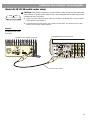
1
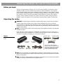
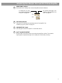
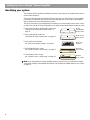
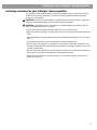
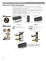
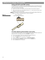
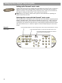
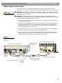
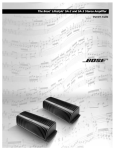
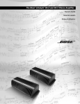
The Bose® Lifestyle® SA-2 and SA-3 Stereo Amplifier
Owner’s Guide
Safety Information
WARNING: To reduce the risk of fire or electrical shock, do not expose the product to rain or moisture.
WARNING: The apparatus shall not be exposed to dripping or splashing, and objects filled with
liquids, such as vases, shall not be placed on the apparatus. As with any electronic products, use
care not to spill liquids into any part of the system. Liquids can cause a failure and/or a fire hazard.
C A U TI ON
AVI
VIS
RISK OF ELECTRICAL SHOCK
DO NOT OPEN
RISQUE DE CHOC ÉLECTRIQUE
NE PAS OUVRIR
CAUTION: TO REDUCE THE RISK OF ELECTRIC SHOCK,
DO NOT REMOVE COVER (OR BACK).
NO USER-SERVICABLE PARTS INSIDE.
REFER SERVICING TO QUALIFIED PERSONNEL.
ATTENTION : POUR RÉDUIRE LE RISQUE DE DÉCHARGE
ÉLECTRIQUE, NE RETIREZ PAS LE COUVERCLE (OU
L’ARRIÈRE). IL NE SE TROUVE ÀL’INTÉRIEURAUCUNE
PIÈCE POUVANT ÊTRE RÉPARÉE PARL’USAGER.
S’ADRESSER À UN RÉPARATEUR COMPÉTENT.
These CAUTION marks are located on the enclosure of your product:
The exclamation point within an equilateral triangle, as marked on the system, is
intended to alert the user to the presence of important operating and maintenance
instructions in this owner’s guide.
The lightning flash with arrowhead symbol within an equilateral triangle alerts the
user to the presence of uninsulated dangerous voltage within the system enclosure
that may be of sufficient magnitude to constitute a risk of electrical shock.
Class B emissions
This Class B digital apparatus meets all requirements of the Canadian Interference-Causing
Equipment Regulations.
CAUTION: To prevent electric shock, match the wide blade of the line cord plug to the wide slot
of the AC (mains) receptacle. Insert fully.
CAUTION: This product is not designed for use in recreational vehicle or marine applications.
WARNING: No naked flame sources, such as lighted candles, should be placed on the apparatus.
Note: The product label is located on the bottom of the product.
Please read this owner’s guide
Please take the time to follow the instructions in this owner’s guide carefully. It will help you
set up and operate your system properly and enjoy all of its advanced features. Please save
this owner’s guide for future reference.
©2004 Bose Corporation. No part of this work may be reproduced, modified, distributed or otherwise used
without prior written permission. All trademarks referenced herein are property of Bose Corporation.
All rights reserved. Bose, Acoustimass, Lifestyle, Personal and Wave are registered trademarks of Bose
Corporation.
2
Important Safety Instructions
1.
2.
3.
4.
5.
6.
7.
8.
9.
10.
11.
12.
13.
14.
15.
16.
17.
18.
19.
Read these instructions – for all components before using this
product.
Keep these instructions – for future reference.
Heed all warnings – on the product and in the owner’s guide.
Follow all instructions.
Do not use this apparatus near water or moisture – Do not
use this product near a bathtub, washbowl, kitchen sink, laundry
tub, in a wet basement, near a swimming pool, or anywhere else
that water or moisture are present.
Clean only with a dry cloth – and as directed by Bose® Corporation. Unplug this product from the wall outlet before cleaning.
Do not block any ventilation openings. Install in accordance
with the manufacturer’s instructions – To ensure reliable operation of the product and to protect it from overheating, put the product in a position and location that will not interfere with its proper
ventilation. For example, do not place the product on a bed, sofa, or
similar surface that may block the ventilation openings. Do not put it
in a built-in system, such as a bookcase or a cabinet that may keep
air from flowing through its ventilation openings.
Do not install near any heat sources, such as radiators, heat
registers, stoves or other apparatus (including amplifiers)
that produce heat.
Do not defeat the safety purpose of the polarized or grounding-type plug. A polarized plug has two blades with one
wider than the other. A grounding-type plug has two blades
and a third grounding prong. The wider blade or third prong
are provided for your safety. If the provided plug does not fit
in your outlet, consult an electrician for replacement of the
obsolete outlet.
Protect the power cord from being walked on or pinched,
particularly at plugs, convenience receptacles, and the point
where they exit from the apparatus.
Only use attachments/accessories specified by the manufacturer.
Use only with the cart, stand, tripod, bracket
or table specified by the manufacturer or
sold with the apparatus. When a cart is used,
use caution when moving the cart/apparatus
combination to avoid injury from tip-over.
Unplug this apparatus during lightning storms or when
unused for long periods of time – to prevent damage to this
product.
Refer all servicing to qualified service personnel. Servicing
is required when the apparatus has been damaged in any
way: such as power-supply cord or plug is damaged; liquid
has been spilled or objects have fallen into the apparatus;
the apparatus has been exposed to rain or moisture, does
not operate normally, or has been dropped – Do not attempt to
service this product yourself. Opening or removing covers may
expose you to dangerous voltages or other hazards. Please call
Bose to be referred to an authorized service center near you.
To prevent risk of fire or electric shock, avoid overloading
wall outlets, extension cords, or integral convenience receptacles.
Do not let objects or liquids enter the product – as they may
touch dangerous voltage points or short-out parts that could result
in a fire or electric shock.
See product enclosure bottom for safety related markings.
Use Proper Power Sources – Plug the product into a proper
power source, as described in the operating instructions or as
marked on the product.
Avoid Power Lines – Use extreme care when installing an outside
antenna system to keep from touching power lines or circuits, as
contact with them may be fatal. Do not install external antennas
near overhead power lines or other electric light or power circuits,
nor where an antenna can fall into such circuits or power lines.
20. Ground All Outdoor Antennas – If an external antenna or cable
system is connected to this product, be sure the antenna or cable
system is grounded. This will provide some protection against voltage surges and built-up static charges.
Section 810 of the National Electrical Code ANSI/NFPA No. 70 provides information with respect to proper grounding of the mast and
supporting structure, grounding of the lead-in wire to an antenna
discharge unit, size of grounding conductors, location of antennadischarge unit, connection to grounding electrodes, and requirements for the ground electrode. Refer to the antenna grounding
illustration on this page.
Antenna grounding
Example of antenna grounding as per National Electrical Code,
ANSI/NFPA 70.
Antenna lead-in wire
Ground clamp
Antenna discharge unit
(NEC Section 810-20)
Grounding conductors
(NEC Section 810-21)
Electric service
equipment
Ground clamps
Power service grounding electrode
system (NEC ART 250, Part H)
Note to CATV system installer
This reminder is provided to call the CATV system installer’s attention to
Article 820-40 of the NEC (of USA) that provides guidelines for proper
grounding. In particular, it specifies that the cable ground shall be connected to the grounding system of the building, as close to the point of
cable entry as is practical.
Information about products that generate
electrical noise
If applicable, this equipment has been tested and found to comply with
the limits for a Class B digital device, pursuant to Part 15 of the FCC
rules. These limits are designed to provide reasonable protection against
harmful interference in a residential installation. This equipment generates, uses, and can radiate radio frequency energy and, if not installed
and used in accordance with the instructions, may cause harmful interference to radio communications. However, this is no guarantee that interference will not occur in a particular installation. If this equipment does
cause harmful interference to radio or television reception, which can be
determined by turning the equipment off and on, you are encouraged to
try to correct the interference by one or more of the following measures:
• Reorient or relocate the receiving antenna.
• Increase the separation between the equipment and receiver.
• Connect the equipment to an outlet on a different circuit than the one
to which the receiver is connected.
• Consult the dealer or an experienced radio/TV technician for help.
Note: Unauthorized modification of the receiver or radio remote control
could void the user’s authority to operate this equipment.
This product complies with the Canadian ICES-003 Class B
specifications.
3
Contents
Introducing the Lifestyle® SA-2 and SA-3 Stereo Amplifier . . . . . . . . . . . . . . . . . . . . . . . . . . . . . .
Before you begin . . . . . . . . . . . . . . . . . . . . . . . . . . . . . . . . . . . . . . . . . . . . . . . . . . . . . . . . . . .
Unpacking the carton . . . . . . . . . . . . . . . . . . . . . . . . . . . . . . . . . . . . . . . . . . . . . . . . . . . . . . . .
Connection panel features . . . . . . . . . . . . . . . . . . . . . . . . . . . . . . . . . . . . . . . . . . . . . . . . . . . .
5
5
5
6
Setting Up Your Lifestyle® Stereo Amplifier . . . . . . . . . . . . . . . . . . . . . . . . . . . . . . . . . . . . . . . . . .
Identifying your system . . . . . . . . . . . . . . . . . . . . . . . . . . . . . . . . . . . . . . . . . . . . . . . . . . . . . .
Selecting a location for your Lifestyle® stereo amplifier . . . . . . . . . . . . . . . . . . . . . . . . . . . . . .
Mounting your Lifestyle® stereo amplifier . . . . . . . . . . . . . . . . . . . . . . . . . . . . . . . . . . . . . . . . .
Model AV-18/38/48 media center setup . . . . . . . . . . . . . . . . . . . . . . . . . . . . . . . . . . . . . . . . .
Model AV-28 media center setup . . . . . . . . . . . . . . . . . . . . . . . . . . . . . . . . . . . . . . . . . . . . . . .
Multi-room interface setup . . . . . . . . . . . . . . . . . . . . . . . . . . . . . . . . . . . . . . . . . . . . . . . . . . . .
Model 20 music center setup . . . . . . . . . . . . . . . . . . . . . . . . . . . . . . . . . . . . . . . . . . . . . . . . . .
Model 5 music center setup . . . . . . . . . . . . . . . . . . . . . . . . . . . . . . . . . . . . . . . . . . . . . . . . . . .
Connecting speakers to your Lifestyle® stereo amplifier . . . . . . . . . . . . . . . . . . . . . . . . . . . . .
Powering-up your system . . . . . . . . . . . . . . . . . . . . . . . . . . . . . . . . . . . . . . . . . . . . . . . . . . . .
8
8
9
10
11
13
15
17
19
21
22
Setting Up Additional Rooms For Sound . . . . . . . . . . . . . . . . . . . . . . . . . . . . . . . . . . . . . . . . . . . .
Setup guidelines for additional rooms . . . . . . . . . . . . . . . . . . . . . . . . . . . . . . . . . . . . . . . . . . .
Setting up remote controls for other rooms . . . . . . . . . . . . . . . . . . . . . . . . . . . . . . . . . . . . . . .
Setting up the amplifier room code . . . . . . . . . . . . . . . . . . . . . . . . . . . . . . . . . . . . . . . . . . . . .
23
23
24
25
Setting Up Advanced Features . . . . . . . . . . . . . . . . . . . . . . . . . . . . . . . . . . . . . . . . . . . . . . . . . . . .
Amplifier mode switches . . . . . . . . . . . . . . . . . . . . . . . . . . . . . . . . . . . . . . . . . . . . . . . . . . . . .
Stereo or mono output (SA-3 only) . . . . . . . . . . . . . . . . . . . . . . . . . . . . . . . . . . . . . . . . . . . . . .
Automatic detection of a local source (SA-3 only) . . . . . . . . . . . . . . . . . . . . . . . . . . . . . . . . . .
Single and supplemental amplifiers . . . . . . . . . . . . . . . . . . . . . . . . . . . . . . . . . . . . . . . . . . . . .
26
26
26
26
26
Maintaining Your Lifestyle® Stereo Amplifier . . . . . . . . . . . . . . . . . . . . . . . . . . . . . . . . . . . . . . . . . .
Cleaning the amplifier . . . . . . . . . . . . . . . . . . . . . . . . . . . . . . . . . . . . . . . . . . . . . . . . . . . . . . . .
Protecting outdoor wiring . . . . . . . . . . . . . . . . . . . . . . . . . . . . . . . . . . . . . . . . . . . . . . . . . . . . .
Troubleshooting . . . . . . . . . . . . . . . . . . . . . . . . . . . . . . . . . . . . . . . . . . . . . . . . . . . . . . . . . . . .
Customer service . . . . . . . . . . . . . . . . . . . . . . . . . . . . . . . . . . . . . . . . . . . . . . . . . . . . . . . . . . .
Limited warranty . . . . . . . . . . . . . . . . . . . . . . . . . . . . . . . . . . . . . . . . . . . . . . . . . . . . . . . . . . . .
Accessories . . . . . . . . . . . . . . . . . . . . . . . . . . . . . . . . . . . . . . . . . . . . . . . . . . . . . . . . . . . . . . .
Technical information . . . . . . . . . . . . . . . . . . . . . . . . . . . . . . . . . . . . . . . . . . . . . . . . . . . . . . . .
27
27
27
27
28
28
28
29
For your records
Record the model number, serial number, and purchase date. The serial number is located on
the bottom panel of your Lifestyle® stereo amplifier.
Model: SA2
SA3
Serial number: ______________________________________
Purchase date: ______________________________________
We suggest you keep your sales receipt and a copy of your product registration card together
with this owner’s guide.
4
Introducing the Lifestyle® SA-2 and SA-3 Stereo Amplifier
Before you begin
Thank you for purchasing a Lifestyle® SA-2 or SA-3 stereo amplifier. The Lifestyle® stereo
amplifier provides you with a simple solution when you want to add Bose® non-powered
environmental speakers or Bose non-powered accessory speakers to your Lifestyle® system.
Bose proprietary Integrated Signal Processing technology, featured in the amplifier, provides
full, rich stereo sound, even when the speakers are playing at low volumes. By using the
Lifestyle® stereo amplifier to expand your system, you can enjoy Bose quality sound and
Lifestyle® system convenience in your yard, patio, swimming deck, garage, or utility room.
Unpacking the carton
WARNING: To avoid danger of suffocation, keep the plastic bags out of the reach of children.
Carefully unpack the shipping carton. Make sure the shipping carton for your Lifestyle®
stereo amplifier includes the parts identified in Figure 1. We recommend saving the packing
materials. You may need them later. The original packing materials provide the safest way to
transport this product.
Note: Locate the serial number on the bottom panel of the amplifier, and write it in the appropriate blank on page 3.
If any part of the product appears to be damaged, do not attempt to use it. Contact your
authorized Bose dealer immediately, or call Bose Customer Service. Refer to the address list
enclosed in the product packaging for correct phone numbers.
Figure 1
Europe (230V)
Australia (240V)
Contents of the shipping
carton
UK/Singapore (230V)
SA-2 stereo
amplifier
120V power cord*
USA/Canada
8-to-9-pin
DIN adapter
SA-3 stereo
amplifier
20-ft Bose® link A cable
*The Lifestyle® stereo amplifier
includes a 120V AC (mains) power
cord for use in the USA and Canada,
or the appropriate 230V or 240V
power cord for international use.
Note: Use only the power cord supplied with your Lifestyle® stereo amplifier. If the power cord
does not fit your power (mains) outlet, DO NOT alter the plug in any way. Contact Bose Customer
Service for assistance.
Note: The Lifestyle® stereo amplifier is designed for use with Bose non-powered environmental
speakers or Bose non-powered accessory speakers ONLY.
5
Introducing the Lifestyle® SA-2 and SA-3 Stereo Amplifier
Connection panel features
The connection panel includes the input/output connections plus room code switches and
amplifier LED status indicators.
Figure 2
Lifestyle® amplifier
connection panel
1
6
2
3
4
5
6
7
1
AC POWER
AC power cord jack. There is no on/off switch on this product. Power is applied when the
power cord is installed and plugged into an AC (mains) receptacle.
2
VCA
Local volume control connection jacks. Allows you to control the volume in a room using a
wall-mounted control. Contact your Bose® dealer or call Bose Customer Service for information on installing this feature. See the contact list inside the back cover of this guide.
3
SPEAKER OUTPUTS
Left and right amplifier speaker outputs. A 6-ohm minimum load is required. To determine the
correct speaker wire size, see “Wire recommendations” on page 29.
Introducing the Lifestyle® SA-2 and SA-3 Stereo Amplifier
4
ROOM CODE switches
Microswitches for setting room code and amplifier advanced features.
For switches A, B, and C,
see “Setting Up Advanced
Features” on page 26.
For switches 6 through 9, see
“Setting up the amplifier room
code” on page 25.
SA-3
A B C 6 7 8 9
SA-2
C 6 7 8 9
5
LED status indicator
The green LED indicates the operational state of the amplifier. See
“Powering-up your system” on page 22.
6
AUX INPUT (SA-3 only)
Left and right channel line inputs for a local audio device.
7
Bose® link INPUT/OUTPUT
Nine-pin DIN connectors used for connecting the amplifier to a Bose® link network.
Input signals are passed through to the output jack to allow daisy chaining.
7
Setting Up Your Lifestyle® Stereo Amplifier
Identifying your system
The Lifestyle® stereo amplifier and additional remote come ready to be installed and used in a
second room (Room B).
This section provides placement and mounting instructions for the Lifestyle® stereo amplifier.
Following this information you will find a section that describes how to set up the amplifier
with your particular home entertainment system.
The set of instructions you need depends on whether you have a media center, music center,
or multi-room interface. The product label on the bottom panel identifies the model you have.
For the AV-18, AV-38, or AV-48 media center, see
“Model AV-18/38/48 media center setup” on
page 11.
Model
AV-18/38/48
media center
For the AV-28 media center, see
“Model AV-28 media center setup” on page 13.
Model AV-28
media center
For the multi-room interface,
see “Multi-room interface setup” on page 15.
Multi-room
interface
For the Model 20 music center,
see “Model 20 music center setup” on page 17.
For the Model 5 music center,
see, “Model 5 music center setup” on page 19.
Model 20
music center
®
®
Model 5
music center
Note: If you are planning to use this amplifier beyond a second room, you will need to change
some switch settings in the amplifier and remote. See “Setting Up Additional Rooms For Sound”
on page 23.
8
Setting Up Your Lifestyle® Stereo Amplifier
Selecting a location for your Lifestyle® stereo amplifier
Your Lifestyle® stereo amplifier does not need to be situated close to either your Lifestyle®
system or the accessory speakers. Consider the following guidelines when selecting a
location for your amplifier.
CAUTION: DO NOT mount the amplifier on surfaces that are not sturdy enough, or that have
hazards concealed behind them, such as electrical wiring or plumbing.
CAUTION: The amplifier must be used indoors. It is neither designed nor tested for use outdoors, in recreational vehicles, or on boats.
• Locate the amplifier indoors and within 8 feet (2.5 m) of a power outlet.
• Make sure that the amplifier is located within the reach of the supplied 20-foot audio input
cable.
• Place the amplifier in an area where the maximum ambient temperature is less than 104°F
(45°C).
• For optimum performance, place the amplifier in a well-ventilated area.
• DO NOT place the amplifier in a completely enclosed area. If adequate ventilation is not
provided, the amplifier will automatically protect itself by reducing its volume level in order
to limit its temperature.
• DO NOT place the amplifier on any heat-sensitive surface, such as the finished surface of
fine furniture. Like all electrical equipment, it generates some heat.
• DO NOT use the amplifier in a damp location. It is important to prevent moisture from
getting into the unit.
9
Setting Up Your Lifestyle® Stereo Amplifier
Mounting your Lifestyle® stereo amplifier
Your Lifestyle® stereo amplifier can be placed on a shelf or mounted on a wall (Figure 3).
• When placing the amplifier on a horizontal surface like a floor or shelf, the amplifier’s rubber
feet provide stability and prevent scratches.
• ONLY when mounting the amplifier on a wall, remove the rubber feet and use the existing
guide holes in the amplifier’s enclosure for mounting hardware. See Figure 4 for recommended mounting methods and hardware.
• When mounting the amplifier vertically or horizontally on a wall, ALWAYS mount the
amplifier in an orientation shown in Figure 3.
Figure 3
Shelf placement
Vertically mounted on wall
Horizontally mounted on wall
Wood wall
Figure 4
Mounting methods and
hardware
Connector panel up
Connector
panel on
the left
Installation options
3
Wallboard
1
/32 in (2.25 mm)
/2 in (12 mm)
(4) #10 x 21/2 in (M5 x 75 mm)
(4) #10 x 11/2 in (M5 x 36 mm)
(4) #10 (M5)
¾ in (1.9 cm) minimum
3
/8 in (0.95 cm) minimum
To mark mounting hole locations, remove
the rubber feet, hold the amplifier in position,
and mark the wall through the clearance
holes in the housing.
10
Setting Up Your Lifestyle® Stereo Amplifier
Model AV-18/38/48 media center setup
CAUTION: Before making connections, turn the Lifestyle® system off and disconnect the media
center from the AC (mains) power outlet. DO NOT plug the amplifier into an outlet until you have
completed all other connections.
1. Insert one end of the Bose® link A cable into the Bose® link output jack on the rear panel
of the media center (Figure 5).
2. Insert the other end of the Bose® link A cable, into the Bose® link input jack on the rear
panel of the Lifestyle® stereo amplifier.
Figure 5
Lifestyle® stereo amplifier to
AV-18/38/48 media center
connections
Lifestyle® stereo amplifier rear panel
AV-18/38/48 media center rear panel
BoseLink
OUTPUT
BoseLink
INPUT
20-ft Bose® link A cable
11
Setting Up Your Lifestyle® Stereo Amplifier
Setting up RC18S2 and RC38S2 remotes
Your additional remote is shipped from the factory already set up for a second room (room B).
To make sure that this remote will work with your home entertainment system, do the following to check the house code setting.
1. Remove the remote control battery cover and locate the microswitches (Figure 6).
2. Make sure that the house code settings (switches 1, 2, 3, and 4) match the house code
settings in your main room remote.
Note: If this remote is to be used beyond a second room, other switch settings will need to be
changed. See “Setting Up Additional Rooms For Sound” on page 23.
Figure 6
Remote microswitches
House code switches
must match main room remote
ON
Check the expansion protocol setting in your system
For the Lifestyle® stereo amplifier to work properly with your home entertainment system, the
expansion protocol menu item must be set to Normal. To verify this:
1. Turn on your Lifestyle® DVD home entertainment system and your TV.
2. Press the System button on your main room remote.
3. Select the Audio tab and navigate down to Expansion Protocol.
4. Verify that the setting Normal is selected. If not, select Normal now.
5. Press the Exit button on the remote.
12
Setting Up Your Lifestyle® Stereo Amplifier
Model AV-28 media center setup
CAUTION: Before making connections, turn the Lifestyle® system off and disconnect the media
center from the AC (mains) power outlet. DO NOT plug the amplifier into an outlet until you have
completed all other connections.
1. Insert the 8-to-9-pin adapter into the SPEAKER ZONES 2 output jack on the rear panel of
the media center (Figure 7).
2. Insert one end of the Bose® link A cable into the 8-to-9-pin adapter.
3. Insert the other end of the Bose® link A cable, into the Bose® link input jack on the rear
panel of the Lifestyle® stereo amplifier.
Figure 7
Lifestyle® stereo amplifier
to AV-28 media center
connections
Lifestyle® stereo amplifier rear panel
AV-28 media center rear panel
BoseLink
OUTPUT
BoseLink
INPUT
8-to-9-pin
DIN adapter
20-ft Bose® link A cable
13
Setting Up Your Lifestyle® Stereo Amplifier
Setting up the RC28S remote
Your second remote is shipped from the factory already set up for Zone 2. To make sure that
this remote will work with your home entertainment system, do the following to check the
house code setting.
1. Remove the remote control battery cover and locate the microswitches (Figure 8).
2. Make sure that the house code settings (switches 1, 2, 3, and 4) match the house code
settings in your main room remote.
3. Make sure switches 5, 7, and 8 are up, and switches 6 and 9 are down.
Note: Refer to your Lifestyle® system owner’s guide for more information on operating your
system in more than one room.
House code switches must
match main room remote
Figure 8
Remote microswitches
ON
Setting the Zone 2 Protocol in your home entertainment system
For the Lifestyle® stereo amplifier to work properly with a Lifestyle® media center, you will
need to set the Zone 2 Protocol to Legacy mode (Figure 9).
1. Turn on your Lifestyle® DVD system and your TV.
2. Press the Settings button on your main room remote control.
3. Scroll down the menu to System Setup and press the Enter button.
4. Scroll down the menu to the last item, Zone 2 Protocol.
5. Press the right arrow remote button to change the protocol from Normal to Legacy.
6. Turn the system off and on again to ensure that the Zone 2 Protocol is reset to Legacy.
Figure 9
Mute
All
On
Off
Setting Zone 2 Protocol
Settings ( )
Mute
System Setup (3 of 3)
SOURCE / INPUT
CD/DVD
Changer
FM/AM
TV
VCR
AUX
MENU / NAVIGATION
Settings
Tune
Disc
Seek
Settings
Enter
Channel
Chapter
Preset
Track
Volume
1
2
4
5
7
8
3
6
9
0
PLAYBACK
Stop
Shuffle
Pause
Play
Repeat
System Setup
14
Enter
Zone 2 Protocol: Legacy
Setting Up Your Lifestyle® Stereo Amplifier
Multi-room interface setup
CAUTION: Before making any connections, turn the Lifestyle® system off and disconnect the
music center from the AC (mains) power outlet. DO NOT plug the amplifier into an outlet until you
have completed all other connections.
1. Insert the 8-to-9-pin adapter into one of the unused ROOM output jacks (B, C, or D) on
the rear of the multi-room interface (Figure 10).
2. Insert one end of the Bose® link A cable into the 8-to-9-pin adapter.
3. Insert the other end of the Bose® link A cable, into the Bose® link input jack on the rear
panel of the Lifestyle® stereo amplifier.
Figure 10
Lifestyle® stereo amplifier
to multi-room interface
connections
Lifestyle® stereo amplifier rear panel
Multi-room interface rear panel
BoseLink
OUTPUT
BoseLink
INPUT
8-to-9-pin
DIN adapter
20-ft Bose® link A cable
15
Setting Up Your Lifestyle® Stereo Amplifier
Setting up the Personal® music center
Systems that have a multi-room interface are controlled by the Personal® music center which
requires no internal switch settings before it allows you to control more than one room of
speakers. However, if you purchase a second Personal® music center, you must follow the
procedure for setting up the Personal® music center for the first time.
Note: Refer to your Lifestyle® system owner’s guide for more information on operating your
system in more than one room.
Selecting other rooms with the Personal® music center
The Personal® music center allows you to control up to four sets of Bose® powered speakers
placed in individual rooms. These rooms are referred to as room A, B, C, and D, with room
A being the primary room (the one used for a one-room system). If two or more rooms are
connected to your system, the Personal® music center displays ROOM and HOUSE buttons,
and room indicators (A, B, C, and/or D). Figure 11 shows a sample display for a two-room
system.
Figure 11
Sample display for a tworoom system
Press the ROOM button to control a single room or two or more rooms that share a source.
Press the HOUSE button to control all connected rooms as one.
The room indicators tell you what was selected
by the ROOM or HOUSE button.
16
Setting Up Your Lifestyle® Stereo Amplifier
Model 20 music center setup
CAUTION: Before making connections, turn the Lifestyle® system off and disconnect the music
center from the AC (mains) power outlet. DO NOT plug the amplifier into an outlet until you have
completed all other connections.
®
1. Insert the 8-to-9-in DIN adapter into the SPEAKER ZONES 2 output jack on the rear
panel of the music center (Figure 12).
2. Insert one end of the Bose® link A cable into the 8-to-9-pin adapter.
3. Insert the other end of the Bose® link A cable, into the Bose® link input jack on the rear
panel of the Lifestyle® stereo amplifier.
4. Set the ROOM CODE switches of the Lifestyle® stereo amplifier to room E
(switch 7 up, switches 6, 8 and 9 down).
A B C 6 7 8 9
See “Setting up the amplifier room code” on page 25.
Figure 12
Lifestyle® stereo amplifier to
Model 20 music center
connections
Lifestyle® stereo amplifier rear panel
Model 20 music center rear panel
BoseLink
OUTPUT
BoseLink
INPUT
8-to-9-pin
DIN adapter
20-ft Bose® link A cable
17
Setting Up Your Lifestyle® Stereo Amplifier
Setting up the RC-20 remote for Zone 2
If your system uses a Model 20 music center, you need to set up a second RC-20 remote
control to operate the ZONE 2 outputs.
1. Remove the remote control battery cover and locate the miniature switches (Figure 13).
2. Make sure that the house code settings (switches 1, 2, 3, and 4) match those in your first
remote.
3. Slide switch 5 down (off), and switches 6 and 8 up (on).
Note: Refer to your Lifestyle® system owner’s guide for more information on operating your
system in more than one room.
Figure 13
RC-20 remote Zone 2
switch settings
ON
K40
l 2 3 4 5 6 7 8
18
Setting Up Your Lifestyle® Stereo Amplifier
Model 5 music center setup
This setup requires a 3-ft audio input adapter cable. Contact your Bose dealer or Bose®
Customer Service. See the list of locations and phone numbers included in the shipping carton.
CAUTION: Before making connections, turn the Lifestyle® system off and disconnect the music
center from the AC (mains) power outlet. DO NOT plug the amplifier into an outlet until you have
completed all other connections.
®
CAUTION: DO NOT connect the audio input cable for the Lifestyle® stereo amplifier to the
SPEAKERS A or SPEAKERS B outputs. The amplifier is designed to work properly with the fixed
output level available from the FIXED OUTPUT jacks.
1. Disconnect the Acoustimass® cable from the FIXED L and R outputs on the rear panel of
the music center (Figure 14).
2. Insert the red RCA piggyback connector of the three-foot audio input adapter cable into
the R (right) FIXED OUTPUT jack. Insert the white RCA piggyback connector into the L
(left) FIXED OUTPUT jack. Insert the 3.5 mm mini-plug into the SYSTEM CONTROL 2
jack on the rear panel of the music center.
3. Insert the red RCA connector of the Acoustimass module cable into the red piggyback
jack and the white RCA connector into the white piggyback jack.
4. Plug one end of the 20-foot audio cable (supplied) into the free end of the three-foot
audio input adapter cable. Plug the other end of the 20-foot audio cable into the Bose®
link input jack on the rear panel of the Lifestyle® stereo amplifier.
Figure 14
Lifestyle® stereo amplifier
to Model 5 music center
connections
Lifestyle® stereo amplifier rear panel
Model 5 music center rear panel
SYSTEM CONTROL 2
3.5 mm mini-plug
BoseLink
OUTPUT
BoseLink
INPUT
Fixed L and
R speaker
outputs
Acoustimass module cable
20-ft Bose® link A cable
3-ft audio input adapter
(available from Bose)
19
Setting Up Your Lifestyle® Stereo Amplifier
Setting up the RC-5 remote
If your system uses a Model 5 music center, you need to set up a second RC-5 remote control to operate your Lifestyle® stereo amplifier.
1. Remove the remote control battery cover and locate the miniature switches (Figure 15).
2. Make sure that the house code settings (switches 1, 2, 3, and 4) match those in your first
remote.
3. Slide switch 5 down (off) and 6 up (on).
Note: Refer to your Lifestyle® system owner’s guide for more information on operating your
system in more than one room.
Figure 15
RC-5 remote switch
settings
ON
K40
l 2 3 4 5 6 7 8
20
Setting Up Your Lifestyle® Stereo Amplifier
Connecting speakers to your Lifestyle® stereo amplifier
CAUTION: DO NOT connect any make or model of powered speakers to the speaker outputs of
the Lifestyle® stereo amplifier. Doing so may cause damage to the equipment.
CAUTION: Make sure that the amplifier is disconnected from AC power before making speaker
connections.
CAUTION: The Lifestyle® stereo amplifier requires a 6-ohm minimum load.
Speaker cord consists of two insulated wires. One wire is usually marked (striped, collared, or
ribbed), indicating that it should be connected to the positive (+) terminal. The plain wire
should always be connected to the negative (–) terminal. For recommended wire sizes and
lengths, see “Wire recommendations” on page 29.
1. Remove the terminal block connector from the SPEAKER OUTPUTS jack on the rear
panel of the amplifier.
2. Connect the left speaker cord to the L positive (+) and minus (–) terminals of the 4-pin
terminal block connector.
3. Connect the right speaker cord to the R positive (+) and minus (–) terminals of the 4-pin
terminal block connector.
4. Plug the terminal block connector into the SPEAKER OUTPUTS jack.
Figure 16
Connecting speaker cable
to SPEAKER OUTPUTS
Rear panel of Lifestyle® stereo amplifier
Positive (+) wire
(marked with stripe)
Terminal block
connector
21
Setting Up Your Lifestyle® Stereo Amplifier
Powering-up your system
CAUTION: DO NOT plug the AC power cord into an AC (mains) outlet until all other connections
are complete.
1. Using the power cord included with your Lifestyle® stereo amplifier, firmly insert the small
connector on one end of the power cord into the AC power jack on the rear panel of the
amplifier (Figure 17).
2. Connect the power cord of the Lifestyle® stereo amplifier and your Lifestyle® music
system to an AC (mains) outlet. The status LED tells you the operational status of the
amplifier.
3. Select a music source with your Personal® music center or your new remote control and
adjust the volume to your liking.
Rear panel of Lifestyle® stereo amplifier
Figure 17
Connecting the power cord
AC power cord
ROOM
CODE
22
Status LED
LED activity
Meaning
Constant slow blinking
(1 sec on, 3 secs off)
Amplifier is off, but plugged into an
AC receptacle.
Constant slow blinking
(1 sec on, 5 secs off)
Amplifier is configured as a supplemental amplifier, turned on, but
plugged into an AC receptacle.
Continuously lit
Amplifier is on and ready to produce
sound.
Lit but rapidly flickering
Amplifier is configured as a supplemental amplifier.
Blinking quickly
Amplifier is receiving data commands through the Bose® link port.
Setting Up Additional Rooms For Sound
Setup guidelines for additional rooms
If you have a Lifestyle® 18 series II, 28 series II, 38 or 48 home entertainment system, you can
experience stereo sound in up to 14 other rooms using Lifestyle® stereo amplifiers, compatible speaker systems and remote controls for the other rooms.
• Remote controls for other rooms must be set to the same house code as the main room
remote, but each remote must be set to a different room code. See “Setting up remote controls for other rooms” on page 24.
• The Lifestyle® amplifier and its remote control must be set to the same room code. See
“Setting up the amplifier room code” on page 25.
• When using more than one amplifier to power more than two speakers in a room (Figure 18,
room C), all amplifiers must be set to the same room code. Also, one amplifier must be set
to the single amp mode and all others must be set to the supplemental amp mode. See
“Single and supplemental amplifiers” on page 26.
Figure 18
Sample installation of
Lifestyle® stereo amplifiers
RC18S
Remote
Control
On
Off
Mute
All
FM·AM
TV
CBL·SAT
Track
Chapter
Preset
Channel
RC38S
Remote
Control
On
Off
Mute
CD·DVD
LOCAL
OR
Mute
All
AUX
OR
RC48
Personal®
Music Center II
FM·AM
TV
CBL·SAT
Track
Chapter
Preset
Channel
VCR
251® speakers
Seek
Repeat
Shuffle
Repeat
Shuffle
1
2
3
1
2
3
4
5
6
4
5
6
7
8
Info
9
7
Last
Info
Switch settings: SA-3
• Room code C
• Single amp
AUX
Volume
Seek
OUT
L R
IN
Mute
CD·DVD
LOCAL
VCR
Volume
Switch settings: SA-3
• Room code C
• Supplemental
amp
Freespace® 51
speakers
ROOM C – Patio
8
9
OUT
L R
IN
Last
0
0
Remote Room Code = C
ROOM B – Bedroom
RC18S
Remote
Control
On
Off
Mute
All
Mute
CD·DVD
FM·AM
TV
CBL·SAT
LOCAL
Track
Chapter
Preset
Channel
OR
RC38S
Remote
Control
On
Off
Mute
All
AUX
VCR
Volume
FM·AM
TV
CBL·SAT
Track
Chapter
Preset
Channel
Seek
1
2
4
5
7
8
Info
0
191 speakers
Switch settings: SA-2
• Room code B
• Single amp
OUT
L R
IN
AUX
VCR
Volume
Seek
Repeat
Shuffle
RC48
Personal®
Music Center II
Mute
CD·DVD
LOCAL
OR
3
6
Repeat
Shuffle
1
2
4
5
9
7
8
Last
Info
3
6
9
Last
0
Remote Room Code = B
ROOM A – Home Theater
Left
Surround
Right
Surround
Lifestyle® system
remote control
Media Center
Main
Acoustimass®
Module
Left
Center
Bose® link
Right
23
Setting Up Additional Rooms For Sound
Setting up remote controls for other rooms
To set up the RC18S or RC38S remote:
1. Remove the remote control battery cover and locate the microswitches (Figure 19).
2. Make sure that the house code settings (switches 1, 2, 3, and 4) match the house code
settings in your main room remote.
3. This remote is shipped from the factory set for room B. If this remote is used beyond a
second room, set switches 6, 7, 8, and 9 to the same room code as set in the Lifestyle®
stereo amplifier.
Note: Refer to your Lifestyle® system owner’s guide for more information on operating your
system in more than one room.
Figure 19
ON
Microswitch settings for
RC18S and RC38S
remotes
RC18S or RC38S
remote
Room
6
7
8
9
B
Down
Down
Down
Up
C
Down
Down
Up
Down
D
Down
Down
Up
Up
E
Down
Up
Down
Down
F
Down
Up
Down
Up
G
Down
Up
Up
Down
H
Down
Up
Up
Up
I
Up
Down
Down
Down
J
Up
Down
Down
Up
K
Up
Down
Up
Down
L
Up
Down
Up
Up
M
Up
Up
Down
Down
N
Up
Up
Down
Up
O
Up
Up
Up
Down
To set up the Personal® Music Center II:
Refer to the owner’s guide included with the Personal® music center II for instructions on
configuring this remote for other rooms.
24
Setting Up Additional Rooms For Sound
Setting up the amplifier room code
The room code of the amplifier must match the room code of the remote used in the room
where the speakers are installed.
Figure 20
Room code switches
Amplifier room code
settings
SA-3
A B C 6 7 8 9
SA-2
C 6 7 8 9
Room
6
7
8
9
B
Down
Down
Down
Up
C
Down
Down
Up
Down
D
Down
Down
Up
Up
E
Down
Up
Down
Down
F
Down
Up
Down
Up
G
Down
Up
Up
Down
H
Down
Up
Up
Up
I
Up
Down
Down
Down
J
Up
Down
Down
Up
K
Up
Down
Up
Down
L
Up
Down
Up
Up
M
Up
Up
Down
Down
N
Up
Up
Down
Up
O
Up
Up
Up
Down
25
Setting Up Advanced Features
Amplifier mode switches
The advanced features of the Lifestyle® stereo amplifier are set up using microswitches A, B,
and C (Figure 21). The SA-3 has all three switches, but the SA-2 has only switch C.
Figure 21
SA-2 and SA-3
microswitches
SA-3
A B C 6 7 8 9
SA-2
C 6 7 8 9
Switch Position Function
A
Down
Mono output
Up*
Stereo output
B
Down*
Up
Local source auto detect Off
Local source auto detect On
C
Down*
Up
Single amp
Supplemental amp
*Factory setting
Stereo or mono output (SA-3 only)
The output of the SA-3 amplifier can be set to stereo (switch A up – factory setting) or mono
(switch A down). The mono output mode feeds left and right channel audio to both the left
and right outputs. This mode is useful in situations where a stereo output isn’t feasible such
as when outdoor speakers are used in a large area.
Automatic detection of a local source (SA-3 only)
When a source is connected to the AUX INPUT jacks, you can set the amplifier to detect
when that source is turned on, thereby automatically switching the amplifier from standby
to on.
The amplifier is shipped with this feature turned off. For local source automatic detection, set
switch B up.
Single and supplemental amplifiers
If you want to cover a large area, such as an outdoor patio, requiring more than one set of
speakers, you can install additional amplifiers. See the setup for room C in “Setup guidelines
for additional rooms” on page 23.
• Leave switch C down (factory setting – single amp mode) on one amplifier and set switch C
up (supplemental amp mode) on all other amplifiers.
• Set the room code in all amplifiers to the same room code as in the remote control.
• Now, you can turn them all on and off, change their volumes, or mute them together using a
single remote control.
26
Maintaining Your Lifestyle® Stereo Amplifier
Cleaning the amplifier
CAUTION: Disconnect the power cord from the AC outlet before cleaning.
The amplifier, which is designed only for indoor use, may become dusty over time. To clean
the amplifier, use only a soft, dry cloth to remove dust from the outside of the enclosure. You
may use a brush attachment on a vacuum cleaner to clean the hard-to-reach areas. DO NOT
use any solvents, chemicals, or cleaning solutions containing alcohol, ammonia, or abrasives.
Protecting outdoor wiring
Although some Bose® speakers are designed and tested to stand up to outdoor weather conditions, the bare ends of the speaker wire can be affected by exposure to the elements. This
is especially true of salt water exposure.
You may use a silicone caulking material, such as RTV adhesive, to protect speaker wire connections. It is commonly available at hardware stores. If you do use caulking, apply it only
after the wires are connected and the knobs tightened down. Check the caulking annually,
and re-apply as needed.
Troubleshooting
If you have a problem operating your Lifestyle® system after installing the Lifestyle® stereo
amplifier, follow the guidelines below. For additional help, see the troubleshooting information
in your system owner’s guide. If the problem still exists, contact your Bose dealer to arrange
for service, or contact Bose Customer Service. Refer to the address list enclosed in the product packaging for correct phone numbers.
Problem
What to do
Neither speaker
plays
• Make sure the Lifestyle® media/music center and the amplifier are plugged in and turned on.
• Make sure the plugs are inserted fully and the outlets are in working order.
• Be sure a music source is selected (AM, FM, CD, AUX, etc.). If CD or AUX is selected, check to be sure there
is a CD in the player or the source connected to AUX is turned on.
• If using a Model 20 music center, make sure the audio input cable is inserted into SPEAKER ZONE 2.
• If using a Model 5 music center for home theater (Lifestyle® 12 or Lifestyle® 8 systems), make sure the
amplifier audio input cable is plugged into the FIXED OUTPUT jacks on the music center. (Then the speaker
output cable to the Acoustimass® module should be connected to the piggyback jacks on the audio input
cable.)
• Disconnect any headphones.
• Make sure the remote control switch settings are correct.
Only one speaker
plays
• Check the wires connected to the speaker that does not play.
• Make sure the wires are in good condition and are firmly connected at both ends.
• See “Connecting speakers to your Lifestyle® stereo amplifier” on page 21.
One speaker still
does not play
• Disconnect the wires from that speaker and the amplifier. Disconnect the other cable from its speaker, and
connect that end of the cable to the speaker that does not play. If the speaker still does not play, the problem is in the speaker. If the speaker now plays, continue checking for the source of the problem.
• Disconnect the same cable from the amplifier. Connect it to the other outputs on the amplifier. If the speaker
plays, the problem is in the original cable that was connected to that speaker. If the speaker does not play,
the problem is in that channel of the amplifier.
Right and left stereo
channels are heard
on the wrong speakers.
• Check the speaker cable connections to be sure the cable connected to the SPEAKER OUTPUTS L at the
amplifier are connected at the other end to the speaker on the left in your listening area.
• Check the speaker cable connections to be sure the cable connected to the SPEAKER OUTPUTS R at the
amplifier are connected at the other end to the speaker on the right in your listening area.
27
Maintaining Your Lifestyle® Stereo Amplifier
Problem
What to do
Bass or treble is
weak
• Check the speaker wire connections. Make sure the wires are connected + to + and – to –.
• See “Connecting speakers to your Lifestyle® stereo amplifier” on page 21.
Interference
• Make sure the speaker wires are firmly inserted in the terminals on the back of the speaker and on the
amplifier rear panel. Check to be sure no wires are touching across terminals.
• See “Connecting speakers to your Lifestyle® stereo amplifier” on page 21.
Remote does not
adjust the volume
• Be sure the 1/8 in (3.5 mm) mini-plug is firmly inserted in the SYSTEM CONTROL 2 jack (Model 5 music
center only).
• If you are using an RC-20 or RC-5 remote control, make sure the remote control switch settings are correct.
• If you are using a local volume control (VCA), turn it to the off position.
Volume
suddenly decreases
• Lower the volume setting to see if the level returns to normal. If so, the sudden loss of volume was an intentional action of the amplifier’s overload protection feature. This engages automatically if the volume is set
too high and is overdriving the speakers. Choosing a lower setting should ensure continuous, even volume.
Zone 2 does not
work at all
• If you are using a Lifestyle® DVD system, the stereo amplifier will not work unless “Zone 2 Protocol” in
the system settings menu is set to “Legacy”. For more information, consult your Lifestyle® DVD system’s
owners guide.
Customer service
For additional help in solving problems, contact Bose® Customer Service. Refer to the
address list enclosed in the product packaging for correct phone numbers.
Limited warranty
The Lifestyle® stereo amplifier is covered by the Bose limited one-year transferable warranty.
Details of the coverage are provided on the product registration card that came with the
product. Please fill out the information section of the card and mail it to Bose. Failure to do so
will not affect your warranty rights.
Accessories
• Bose® link-to-Model 5 adapter cable (PN 000000)
• Bose® link 50-foot extension/expansion cable (PN 275475-050)
28
Maintaining Your Lifestyle® Stereo Amplifier
Technical information
Features
• Bose® proprietary digital signal processing technology
• Built-in digital volume control
• Thermal overload protection
• Protective rubber feet
Power rating
• USA/Canada: 120V
50/60 Hz, 220W (SA-2), 400W (SA-3)
• International: 220-240V
50/60 Hz, 220W (SA-2), 400W (SA-3)
Input sensitivity
• 0.5 Vrms @ 1 kHz
Signal to Noise ratio (S/N)
• 90 dB
SA-2
SA-3
Input/output
jacks
VCA volume control jack
Speaker left/right outputs
Bose® link input/output
VCA volume control jack
Speaker left/right outputs
AUX input
Bose® link input/output
Output power
(continuous ave.)
40W per channel minimum into 6
ohms, from 30 to 15 kHz, with no
more than 0.5% THD.
100W per channel minimum into
6 Ohms, from 30 to 15 kHz, with
no more than 0.5% THD.
Dimensions
14¼"W x 5½"D x 3½"H
(36.2 x 13.8 x 9.0 cm)
14¼"W x 5½"D x 4¼"H
(36.2 cm x 13.8 cm x 10.7 cm)
Weight
7.6 lb (3.42 kg)
11.0 lb (4.95 kg)
Finish
• Black powdercoat
Wire recommendations
Length (max.)
Gauge
30 ft (9 m)
45 ft (14 m)
70 ft (21 m)
18 (0.75 mm2)
16 (1.7 mm2)
14 (2.0 mm2)
29
30
Bose Corporation
USA
Italia
Bose Corporation, The Mountain
Framingham, MA 01701-9168
1-800-367-4008
Phone hours - ET (eastern time):
Weekdays 8:30 a.m. to 8 p.m.
Saturdays 9 a.m. to 3 p.m.
Bose S.p.A., Via della Magliana 876
00148 Roma
TEL 06-65670802
FAX 06-65680167
Canada
Bose Ltd., 1-35 East Beaver Creek Road
Richmond Hill, Ontario L4B 1B3
1-800-465-2673
Phone hours - ET (eastern time):
Weekdays 9 a.m. to 5 p.m.
European Office
Bose Products B.V., Nijverheidstraat 8
1135 GE Edam, Nederland
TEL 0299-390111
FAX 0299-390114
Australia
Bose Pty Limited, 1 Sorrell Street
Parramatta, N.S.W. 2150
TEL 02 9204-6111
FAX 02 9204-6122
Japan
Bose K.K., Shibuya YT Building
28-3 Maruyama-cho
Shibuya-ku, Tokyo 150
TEL 3-5489-0955
FAX 3-5489-0592
Nederland
Bose B.V., Nijverheidstraat 8
1135 GE Edam
TEL 0299-390111
FAX 0299-390109
Norge
Bose A/S, Solheimsgate 11
N-2001, Lillestrøm
TEL 63-817380
FAX 63-810819
Österreich
Belgique/België
Bose Ges.m.b.H., Vienna Business Park
Wienerbergstrasse 7 (10.OG)
A-1100 Vienna
TEL 01-60404340
FAX 01-604043423
Bose N.V., Limesweg 2, B-3700 Tongeren
TEL 012-390800
FAX 012-390840
Schweiz
Danmark
Bose AG, Rünenbergerstrasse 13
4460-Gelterkinden
TEL 061-9815544
FAX 061-9815502
Bose A/S, Industrivej 7, 2605 Brøndby
TEL 4343-7777
FAX 4343-7818
Deutschland
Bose GmbH, Max-Planck-Straße 36d
D-61381 Friedrichsdorf
TEL 06172-71040
FAX 06172-710419
France
Bose S.A., 6, rue Saint Vincent
78100 Saint Germain en Laye
TEL 01-30616363
FAX 01-30614105
India
Sverige
Bose A/S, JohanneFredsgatan 4
S-43153 Mölndal
TEL 31-878850
FAX 31-274891
United Kingdom
Bose Limited
1 Ambley Green
Gillingham Business Park
Gillingham, Kent ME8 ONJ
TEL 0870-741-4500
FAX 0870-741-4545
Bose Corporation India Private Limited
W-16, Greater Kailash-II
New Delhi 110 048
TEL (011) 648 4462
FAX (011) 648 4463
From other locations
Ireland
World Wide Web
Bose Corporation
Carrickmacross, Co Monaghan
TEL (042) 9661988
FAX (042) 9661998
www.bose.com
Bose Customer Service, 1 New York Ave.
Framingham, MA 01701-9168 USA
TEL (508) 766-1900
FAX (508) 766-1919
31
©2004 Bose Corporation, The Mountain,
Framingham, MA 01701-9168 USA
275071 AM Rev.00 CCM-000395
OUR COMMITMENT TO YOU
We take great pride in designing each of our products with the goal of providing the highest accuracy musical performance possible in the price range of that product. We strive to
reproduce the musical sounds as closely as possible to those of the original performance.
And we strive to avoid flashy sounds such as those associated with accentuated bass
and/or treble frequencies. While those sounds may be initially attractive to the novice,
they are not real and are not enduring. In addition, we use only the highest quality parts
and the latest assembly and quality control techniques to ensure the reliability and long
life of our products.
Our reputation rests on our steadfast pursuit of this policy in sound systems for the home,
the automobile, and businesses.
At Bose® we reinvest 100% of our earnings back into the company. This enables us to
support research that continually gives rise to new technologies for improving sound
reproduction.
When you purchase any product from Bose, we encourage you to compare it, as we do, to
competitive products for musical accuracy. We believe that this process will enhance your
appreciation of the product you select.
With best wishes from all of us at Bose for many years of enjoyable listening.
»
~
:0
~
L
§
BOSE CORPORATION, THE MOUNTAIN, FRAMINGHAM, MA 01701-9168 U.S.A. TEL.: 508.879.7330
FAX: 508.766.7543 WWW.BOSE.COM
~
lIorg.e
Bose AlS, Soll4eimsgate 11
N-2001, lillestr0m
TEL 63-817380
Osterreich
Bose Ges.m.b.H., Vienna Business !earl<
Wienerbergstrasse 7 (10.0G)
A-1100 Vienna
TEL 01-60404340
Schweiz
Bose AG, Runenbergerstrasse 13
4460-Gelterkinden
TEL 061-9815544
Sverige
Bose AlS, Jol4annefredsgatan 4>·· · · ·.· · ·.>.>··\.»··.· >·
S-43153 Molndal
TEL 31-878850
United Kingdom
Bose Limited
1 Ambley Green
Gillingl4am Business Park
Gillingl4am, Kent ME8 ONJ
FAX 0870-741-4545
TEL 0870-741-4500
World Wide Web
www.bose.com
--B05~
Better sound through reseamh®
©2002 Bose Corporation
The Mountain, Framingham, MA 01701-9168 USA
259434 AM Rev.02 JN10571
For U.S. And Canadian Residents Only
IMPORTANTI IMPORTANTI IMPORTANTI
PLEASE COMPLETE AND RETURN IMMEDIATELYI
6
Please indicate the serial number(s) of this product.
Register online at http://www.bose.com/register
Initial:
L
I
I
318C
U
I
I
I
I
I
I
I
I
I
I
I
I
I
I
2
I
I
I
I
I
I
I
I
I
I
I
I
I
II
I
I
15b
0 If your comments were selected for use in radio (Paul Harvey or some other radio
personality) or television broadcast, print advertising, or other media, please check
here if you permit these comments to be used with reference to your name.
I
5.0 Catalog
I
6. 0 Other Web site
7.0 Other
I L-I
--L---L---L-_
Email Address:
Date of Purchase: (month/day/year)
I
8a
8b
LLJ ~ L---1-~~1
5
State:
City:
Country:
I
I
I
LJ
[
o Check here if you would like to hear from Bose® by email.
4
I
Name:
State/Province:
Phone Number:
I
3
I
I
4. 0 Retail store
Zip Code/Postal Code:
I
I
Where was product purchased:
I
I
I
3. 0 Bose store
[
City:
I
I
2.0 Bose Web site
Apt#:
I
I
1. 0 Bose® 1-800 number
I
Address: (number and street)
I
I
I
7
Last Name:
I
Please let us know how you are enjoying your new Bose® products.
We value your comments:
Serial number(s):
I
First Name:
15a
(Found on the ID label attached to your product or consult your owner's manual for the location.)
Please indicate Bose product(s) purchased:
1. 0 Wave® radio
17. 0 Acoustimass 10 speakers
2. 0 Wave® radio/CD
18. 0 Acoustimass 15 speakers
3. 0 Wave/PCTM interactive
19. 0 3-2-1 entertainment system NEW
system NEW
20.0 Lifestyle® 5 music system
4. 0 Acoustic Wave® music system
21. 0 Lifestyle® 12 theater system
5.0 141® speakers
22. 0 Lifestyle® 20 music system
6.0 151® speakers
23. 0 Lifestyle® 28 entertainment system NEW
7. 0 161™speakers NEW
24.0 Lifestyle® 35 entertainment system NEW
8. 0 201 ®speakers
25.0 Lifestyle® 50 theater system
9. 0 251™ speakers
26. 0 Lifestyle® powered speakers
1O. 0 301 ®speakers
27. 0 VCS-1 O® center speaker
11. 0 601 ™speakers NEW
28. 0 Headset X
12.0 701® speakers NEW
29. 0 QuietComfort™ headset NEW
13. 0 901 ®speakers
30. 0 Other, please specify
14. 0 Acoustimass® 3 speakers
15.0 Acoustimass 5 speakers
16. 0 Acoustimass 6 speakers
9
10
Do you own any other Bose products?
1. 0 Yes
Which ones?
1. 0 Lifestyle® system
2.0 Wave® radio/Acoustic Wave® system
3. 0 Automobile sound system
4. 0 Acoustimass® speakers
5.0 Headset
6.0 Other Bose speakers
7.0 Other
Date of YQ1[ birth: (month/day/year)
'--------.----L-------!
L------l-_L-------l--------l
Including yourself. what is the total number of people living in your household?
(Example: 01, 02, 03, 04...)
11
LLJ
2. 0 No
LJ
Date of birth (month/year) of the other adults and children in your household:
Male
Female
1.0 2.0
Male
~I
I
Year
Month
1.0 2.0
~l
1.0 2.0
~I
Month
12
Your gender:
13
Your marital status:
14
For your primary residence, do you:
1.0 Male
~I
Month
I
Year
Month
Female
1.0 2.0
2.0 Female
1.0 Married
2.0 Single
1.00wn
2.0 Rent
Year
Year
CONTINUED ON OTHER SIDE
__1 - - - - - - - - - - - - - - - - - - - - - - - - - - - - - - - - - - - - - - - - - - - - - - - - - - - - - - - - - - - - - - - - - - - - - - - - - - - -...e.
~
:
16
Which best describes your family income?
1.0 Under $15,000
7.0$100,000-$124,999
2. 0 $15,000-$24,999
8. 0 $125,000-$149,999
3. 0 $25,000-$34,999
9. 0 $150,000-$174,999
4. 0 $35,000-$49,999
10. 0 $175,000-$199,999
5. 0 $50,000-$74,999
11. 0 $200,000-$249,999
6. 0 $75,000-$99,999
12. 0 $250,000 or over
17
Education: (Please check which category applies to you)
1. 0 Some high school
2. 0 Completed high school
3. 0 College degree
4. 0 Graduate degree
18
In the last six (6) months has anyone in your household purchased any of the
following items through the mail and/or over the Internet?
A. Mail
B. Internet
o
1. Books/magazines
o
2. Children's products
o
o
3. Clothes
o
o
4. Insurance/financial products
o
o
o
5. MusicNideo/DVD
o
6. Travel
o
o
7. Other
o
o
19a
0 Some Bose® systems contain software which is critical for their operation.
We may offer software upgrades in the future to enhance your system
functionality. Please check here if you do not want to be contacted
regarding software upgrades.
19b
0 Check here if you do not want to hear about other Bose products.
19c
0 Check here if you do not wish to receive information from other reputable
companies that offer new and exciting products and services.
en
:sen
u.J
(.)
:s
(.)
~
en
0:
u::::
0-
~ ~
<Do
..c
-Q.)
+-J
0..0
~oo
000
oo<D
~
+-J
U "0
:::J "0
I
I
I
I
I
I
I
I
I
I
I
I
I
I
I
I
"Oro
2Q.)
0..£
"00
c: +-J
Q.)Q.)
oou
c:
+-J
OQ.)
c:"O
oC:
"0
PLEASE FOLD AND SEAL WITH TAPE BEFORE MAILING.
DO NOT STAPLE.
~ e~---------------llllllllJe
0
~~
roe
<D~
0
a..
u
0-
~
u.J
0:
~ u.J
en :::c
I
Bose® Product
Please Keep This Warranty Information
Card With Your Owner's Guide.
What is covered:
All parts defective in material and workmanship. This limited warranty does not cover a
defect that has resulted from improper or unreasonable use or maintenance, accident,
excess moisture, improper packing, lightning, power surges, or unauthorized tampering,
alteration or modification.
Limitation on Liability:
THE PROVISIONS OF THIS LIMITED WARRANTY ARE IN LIEU OF ANY OTHER WRITTEN WARRANTY, WHETHER EXPRESS OR IMPLIED, WRITTEN OR ORAL, INCLUDING ANY WARRANTY OF
MERCHANTABILITY OR FITNESS FOR A PARTICULAR PURPOSE. Notwithstanding the above,
where applicable, if you qualify as a"consumer" under the Magnuson-Moss Warranty Act, then
you may be entitled to any implied warranties allowed by law for the period of the express warranty as set forth below. Some states do not allow limitations on how long an implied warranty lasts, so the above limitation may not apply to you.
For how long:
The Bose Limited Warranty lasts one year from the purchase date for electronic products,
systems, and powered speaker components, and five years for speaker components that are
not self-powered (amplified). Integrated, stereo, and home theater systems have a one year
Limited Warranty. Additionally, the 131 ® marine speakers have a three year Limited
Warranty. Powered component speakers have aone year Limited Warranty term for the electronics and five years for the speakers. The Headset X has a two year Limited Warranty,
excluding the ear cushions, which have a 6 month Limited Warranty. The QuietComfort™
headset has a 1 year Limited Warranty. Please see your Owner's Guide for details. For the
Limited Warranty on professional products, please refer to your Owner's Guide for details.
What we will do:
We will, at our sole option, repair or replace any defective parts within a reasonable period of
time and free of charge.
What we will not do:
Pay shipping or transportation charges from you to us.
What you must do to obtain Warranty Service:
1. Return product with proof of purchase from an authorized Bose dealer to a Bose Service
Agency, or
2. Return product with proof of purchase from an authorized Bose dealer directly to Bose
Corporation. If you elect to return the product directly to Bose Corporation, the following procedures must be followed.
a) Contact Bose Corporation for specific return and shipping instructions, which will include
but may not be limited to;
b) Properly packing the product in the original carton for shipping. If you need a new carton, contact Bose Corporation for a new carton available at a nominal charge;
Warranty information continued on other side
Continued from other side
c) Labeling and shipping, freight prepaid, to Bose® Corporation, Product and Technical
Support, The Mountain, Framingham, MA 01701-9168 or the one provided by Bose
Corporation. You may also write to this address to obtain information about this limited
warranty.
d) Placing any necessary return authorization number prominently on the outside of the carton. (Cartons not bearing a return authorization number where required will be refused.)
Exclusive Remedy:
This limited warranty is fully transferable provided that the current owner furnishes the original
proof of purchase from an authorized Bose dealer. THE MAXIMUM LIABILITY OF BOSE SHALL
NOT EXCEED THE ACTUAL PURCHASE PRICE PAID BY YOU FOR THE PRODUCT. IN NO EVENT
SHALL BOSE BE LIABLE FOR SPECIAL, INCIDENTAL, CONSEQUENTIAL OR INDIRECT DAMAGES.
Some places do not allow limitations on the exclusion or limitation of relief, special, incidental,
consequential or indirect damages, or the limitation of liability to specified amounts, so the
above limitations or exclusions may not apply to you.
Other conditions:
This limited warranty gives you specific legal rights, and you may also have other rights which
vary from country to country or state to state. This limited warranty is void if the label bearing
the serial number has been removed or defaced. Your warranty rights are not diminished if you
do not complete and return this card.
••••
Bose Corporation thanks you for your recent Bose product purchase.
We know it will give you years of satisfaction.
For your benefit, we recommend that you record your serial number(s), found on the product(s),
and other purchase information on this card and keep it with your personal records along with
proof of purchase. If necessary, this information will allow us to better serve your needs.
Model Name or Number:
_
Serial Number(s):
_
Date Purchased:
_
Dealer's Name:
_
Dealer's Address:
Please refer to your Owner's Guide for the list of Warranty Service Centers.
Please send any correspondence regarding product information
or warranty services to:
Bose Corporation, The Mountain, Framingham, MA 01701-9168
(508) 879-7330 or toll-free (800) 444-BOSE