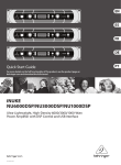
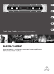
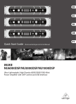
1
Electro-Voice X-Array Touring Loudspeaker Systems Application Notes Rev.: 4.01 - 09/01/99 PREFACE This document, the Electro-Voice X-Array™ Touring Loudspeaker Systems – Applications Notes provide useful information for setting up and operating the X-Array loudspeaker systems. These notes cover amplifier recommendations, digital signal processing, loudspeaker service information and available XArray accessories. The Xw floor monitor systems are auxiliary members of the X-Array™ product line and are briefly mentioned; however, these application notes primarily discuss the main X-Array™ loudspeaker systems. A history of revisions to these applications notes is included at the end of this document. This document does not include rigging information. For rigging information, the user should consult the X-Array Loudspeaker Systems – Flying Manual and Structural Ratings. Before suspending any XArray™ loudspeaker system overhead, the user should be familiar with the rigging concepts, structural ratings and safety information presented in the flying manual. A copy of that manual is shipped with each flying loudspeaker, and is additionally available at no charge from Electro-Voice. X-Array Touring Loudspeaker Systems – Applications Notes – Page i Table of Contents 0. INTRODUCTION 1. LOUDSPEAKER-SYSTEM INFORMATION 1.1 Loudspeaker-Component Impedance 1.2 Loudspeaker-System Wiring & Connections 1.3 Loudspeaker-System Polarity 1.4 Power-Amplifier Requirements X-Array Systems Recommendations Xw Systems Recommendations 1.5 Identifying & Marking Enclosures 2. GENERAL DIGITAL-SIGNAL PROCESSING 2.1 Signal-Processing Overview 2.2 Loudspeaker-System Considerations 2.3 Signal-Processing Zones 2.4 Amplifier Considerations 2.5 Equalization Parameters 2.6 High- & Low-Pass Filters 2.7 Gain Parameters Input-Level Adjustments Output-Level Adjustments Optimizing The Gain Structure 2.8 Signal-Delay Parameters Loudspeaker-Component Alignment Loudspeaker-System Alignment Enclosure-Misalignment Compensation 2.9 Limiter Parameters Calibrating the Limiters 3. LOUDSPEAKER ARRAYS 3.1 Preliminary Overview 3.2 Preliminary X-Array Applications Guide - - - - - - - - - - - 1 1 1 2 4 5 5 5 6 6 6 6 7 7 8 8 8 8 8 9 10 10 10 11 12 13 14 14 14 APPENDICES A. SERVICING THE X-ARRAY SYSTEMS A.1 General Information A.2 Typical Service Parts X-Array Systems Xw Floor Monitors A.3 X-Array System Specific Service Instructions A.4 Xw Specific Service Instructions B. X-ARRAY LOUDSPEAKER ACCESSORIES B.1 Rigging Accessories B.2 Electronic Accessories B.3 Miscellaneous Accessories C. LF & SUB POLARITY WIRING D. KT DN8000 DIGITAL-SIGNAL PROCESSING D.1 Loudspeaker-System Setups D.2 Loudspeaker System and Configuration Considerations D.3 Option-Menu Parameters D.4 Equalization Parameters D.5 High- & Low-Pass-Filter Parameters D.6 Gain Parameters Input-Level Adjustments Output-Level Adjustments Optimizing The Gain Structure D.7 Signal-Delay Parameters Signal-Delay Displays with Different Operating-System Revisions Operating System Revision 1.19 and Earlier Operating-System Revision 1.20 and Later X-Array Touring Loudspeaker Systems – Applications Notes – Page ii - 16 16 16 16 16 17 18 18 18 19 19 20 20 20 22 22 23 23 23 24 24 25 24 25 25 25 Loudspeaker-Component Alignment Loudspeaker-System Alignment Enclosure-Misalignment Compensation D.8 Limiter Parameters D.9 Compressor Parameters D10 Gate (Expander) Parameters D.11 Mute Parameters HISTORY OF REVISIONS - - - - - - - - - - - - 25 26 26 27 28 29 29 - - - - - - - - - - - - - 29 FIGURES Figure 1 – Loudspeaker Systems Figure 2 – Wiring Diagrams - - - - - - - - - - - - - 30 34 X-Array Touring Loudspeaker Systems – Applications Notes – Page iii 0. INTRODUCTION The X-Array™ product line represents important advancements in concert-sound technology. The design goals called for the highest acoustic output capability with the highest fidelity, in lightweight, compact enclosures that were easy to array. The development began with a clean sheet of paper and took an integrated approach. The individual loudspeaker drivers, horns, enclosures, rigging, hardware and system configurations were designed from the ground up specifically for this high-performance application. Figure 1 illustrates the X-Array™ product line and a brief description of each model is included below. Consult the individual system engineering data sheets for detailed specifications. Xf: Far-field, two-way mid-bass/high-frequency (MB/HF) loudspeaker system with a 40H°x20V° coverage pattern. The system has two ND12A 305-mm (12-inch) MB drivers and two ND5-16 76-mm (3-inch) HF compression drivers. The Xf utilizes the standard full-size X-Array™ enclosure shell and the standard XArray™ flying hardware. Xn: Near-field, three-way, semi-full-range, low-frequency/mid-bass/high-frequency (LF/MB/HF) loudspeaker system with a rotatable 60°x40° coverage pattern. The system has one EVX-180B 457-mm (18inch) LF driver, one ND12A 305-mm (12-inch) MB driver and one ND5-16 76-mm (3-inch) HF compression driver. The Xn utilizes the standard full-size X-Array™ enclosure shell and the standard X-Array™ flying hardware. Xb: Bass loudspeaker system with two EVX-180B 457-mm (18-inch) low-frequency (LF) drivers. The Xb utilizes the standard full-size X-Array™ enclosure shell and the standard X-Array™ flying hardware. Xds: Double subwoofer loudspeaker system with two EVX-180B 457-mm (18-inch) subwoofer (SUB drivers. The Xds utilizes the double-wide X-Array™ enclosure shell and does not have flying hardware. Xcn: Compact near-field, two-way mid-bass/high-frequency (MB/HF) loudspeaker system with a rotatable 60°x40° coverage pattern. The system has one ND12A 305-mm (12-inch) MB driver and one ND5-16 76-mm (3-inch) HF compression driver. The Xcn utilizes the half-size X-Array™ enclosure shell and the standard X-Array™ flying hardware. Xcb: Compact bass loudspeaker system with one EVX-180B 457-mm (18-inch) low-frequency (LF) driver. The Xcb utilizes the half-size X-Array™ enclosure shell and the standard X-Array™ flying hardware. Xw12: Wedge floor-monitor, two-way, full-range loudspeaker system with a 55H°x80V° coverage pattern. The system has one custom 305-mm (12-inch) low-frequency (LF) driver and one DH6-16 76-mm (3-inch) high-frequency (HF) compression driver. The Xw12 utilizes a mirror-image slanted shell and does not have flying hardware. Xw15: Wedge floor-monitor, two-way, full-range loudspeaker system with a 55H°x80V° coverage pattern. The system has one custom 381-mm (15-inch) low-frequency (LF) driver and one DH6-16 76-mm (3-inch) high-frequency (HF) compression driver. The Xw15 utilizes a mirror-image slanted shell and does not have flying hardware. 1. LOUDSPEAKER-SYSTEM INFORMATION 1.1 Loudspeaker-Component Impedance All of MB and HF drivers in the X-Array™ loudspeaker systems have a nominal impedance of 16 ohms each, while all of the LF and SUB drivers have a nominal impedance of 8 ohms each. When two MB drivers are used in the same enclosure (such as in the Xf), the drivers are paralleled inside the enclosure for an overall 8-ohm nominal MB system impedance. Likewise, when two HF drivers are used in the same enclosure (again as in the Xf), the drivers are paralleled inside the enclosure for an overall nominal 8-ohm HF system impedance. When two LF or SUB drivers are used in the same enclosure (such as in the Xb or Xds), the drivers are not paralleled, but rather wired to different sets of connector pins on the input panel presenting two nominal 8-ohm loads. Knowledge of the system nominal impedances is essential for planning amplifier loads and cabling. The wiring diagrams of all of the X-Array™ loudspeaker systems are shown in Figure 2. X-Array Touring Loudspeaker Systems – Applications Notes – Page 1 Figure 2 indicates the nominal system impedance of each section as well as the DC resistance of each section. The DC resistance of the drivers inside the enclosure may be measured with a standard voltohm meter (VOM) at the input panel. The DC resistances are useful for troubleshooting individual loudspeaker systems without opening up the loudspeaker enclosure. 1.2 Loudspeaker-System Wiring and Connections The main X-Array™ touring systems (excluding the Xw floor monitors) all utilize two 8-pin Neutrik Speakon connectors on each system input panel. The HF drivers are always wired on Pins 4+ and 4-, the MB drivers are always wired on Pins 3+ and 3-, and the LF and SUB drivers are always wired on Pins 2+ and 2- and Pins 1+ and 1-. All eight pins are connected and are passed through from the input to the output connector on every loudspeaker system. This wiring scheme minimizes the number of speaker cables that must be run to the amplifier racks to power an X-Array™ loudspeaker system. The Xw floor monitors all have two input panels – one on each end. Each input panel has a pair of 4-pin Neutrik Speakon connectors. This provides maximum flexibility for planning amplifier cable runs, minimizing a cluttered appearance on the stage. The HF drivers are wired on Pins 2+ and 2- and the LF drivers are wired on Pins 1+ and 1-. All of the pins are paralleled to each of the four connectors. All of the loudspeaker systems (both main X-Array™ touring and Xw) use the same internal wiring color code. All HF sections use a white (+) and black (-) pair of wires, all MB sections use a blue (+) and black (-) pair of wires, and all LF and SUB sections use a red (+) and black (-) pair of wires. The wiring diagrams for all of the X-Array™ loudspeaker systems are shown in Figure 2 and a brief description of the wiring-connection capabilities of each system is described below: Xb: Two paralleled 8-pin Neutrik Speakon connectors are used for electrical connection on the input panel. Because the connectors are paralleled, it does not matter which connector is used as the input or output when paralleling Xb systems. One LF driver is connected on Pins 1 and one LF driver is connected on Pins 2. Although Pins 3 and 4 are not used internally in the Xb system, they are paralleled on the input panel. This allows an X-Array™ MB/HF box (like the Xf – which uses Pins 3 and 4, but not 1 and 2) to be paralleled with an Xb, allowing all eight conductors to be used in a single cable run to the amplifiers. When two Xb systems are jumped from one to another via the paralleled input-panel connectors, the amplifier home-run cable will have two LF drivers on Pins 2 (for a 4-ohm load) and two LF drivers on Pins 1 (for a 4-ohm load). Xds: Two paralleled 8-pin Neutrik Speakon connectors are used for electrical connection on the input panel. Because the connectors are paralleled, it does not matter which connector is used as the input or output when paralleling Xds systems. Like the Xb, one SUB driver is connected on Pins 1 and one SUB driver is connected on Pins 2. Although Pins 3 and 4 are not used internally in the Xds system, they are paralleled on the input panel. This allows an X-Array™ MB/HF box (like the Xf – which uses Pins 3 and 4, but not 1 and 2) to be paralleled with an Xds, allowing all eight conductors to be used in a single cable run to the amplifiers. When two Xds systems are jumped from one to another via the paralleled inputpanel connectors, the amplifier home-run cable will have two SUB drivers on Pins 2 (for a 4-ohm load) and two SUB drivers on Pins 1 (for a 4-ohm load). Xf: Two paralleled 8-pin Neutrik Speakon connectors are used for electrical connection on the input panel. Because the connectors are paralleled, it does not matter which connector is used as the input or output when paralleling Xf systems. Both HF drivers are paralleled on Pins 4 and both MB drivers are paralleled on Pins 3. Although Pins 1 and 2 are not used internally in the Xf system, they are paralleled on the input panel. This allows an X-Array™ LF box (like the Xb – which uses Pins 1 and 2, but not 3 and 4) to be paralleled with an Xf, allowing all eight conductors to be used in a single cable run to the amplifiers. When two Xf systems are jumped from one to another via the paralleled input-panel connectors, the amplifier home-run cable will have four HF drivers on Pins 4 (for a 4-ohm load) and four MB drivers on Pins 3 (for a 4-ohm load). X-Array Touring Loudspeaker Systems – Applications Notes – Page 2 Xn: Two semi-paralleled 8-pin Neutrik Speakon connectors are used for electrical connection on the input panel. Note that one connector is specifically labeled for input connection and the other for output connection. Pins 3 and 4 are paralleled between the two connectors; however, Pins 1 In are connected to Pins 2 Out, while Pins 2 In are connected to Pins 1 Out. The HF driver is connected on Pins 4 In and Out, the MB driver is connected on Pins 3 In and Out, and the LF driver is connected to Pins 1 In and Pins 2 Out. This facilitates the amplifier wiring of multiple systems. When four Xn systems are jumped from one to another via connection from output to input connectors, the amplifier home-run cable will have four HF drivers on Pins 4 (for a 4-ohm load), four MB drivers on Pins 3 (for a 4-ohm load), two LF drivers on Pins 2 (for a 4-ohm load) and two LF drivers on Pins 1 (for a 4-ohm load). When jumping boxes from output to input connectors, the LF drivers alternate from Pins 1 to Pins 2 as successive boxes are added to the chain. However, a wiring “trick” may be employed if it is desired to keep all of the LF drivers on Pins 1 by plugging into the input of the first box, then jumping from the output of the first box to the output of the second box – resulting in two HF drivers on Pins 4, two MB drivers on Pins 3 and two LF drivers on Pins 1 with nothing on Pins 2. A similar wiring “trick” may be employed to keep all of the LF drivers on Pins 2 by plugging into the output of the first box, then jumping from the input of the first box to the input of the second box. Xcn: Two paralleled 8-pin Neutrik Speakon connectors are used for electrical connection on the input panel. Because the connectors are paralleled, it does not matter which connector is used as the input or output when paralleling Xcn systems. The HF driver is connected on Pins 4 and the MB driver is connected on Pins 3. Although Pins 1 and 2 are not used internally in the Xcn system, they are paralleled on the input panel. This allows an X-Array™ LF box (like the Xcb or Xb – which use Pins 1 and 2, but not 3 and 4) to be paralleled with an Xcn, allowing all eight conductors to be used in a single cable run to the amplifiers. When four Xcn systems are jumped from one to another via the paralleled input-panel connectors, the amplifier home-run cable will have four HF drivers on Pins 4 (for a 4-ohm load) and four MB drivers on Pins 3 (for a 4-ohm load). Xcb: Two semi-paralleled 8-pin Neutrik Speakon connectors are used for electrical connection on the input panel. Note that one connector is specifically labeled for input connection and the other for output connection. Pins 3 and 4 are paralleled between the two connectors; however, Pins 1 In are connected to Pins 2 Out, while Pins 2 In are connected to Pins 1 Out. The LF driver is connected to Pins 1 In and Pins 2 Out. This facilitates the amplifier wiring of multiple systems. When four Xcb systems are jumped from one to another via connection from output to input connectors, the amplifier home-run cable will have two LF drivers on Pins 2 (for a 4-ohm load) and two LF drivers on Pins 1 (for a 4-ohm load). When jumping boxes from output to input connectors, the LF drivers alternate from Pins 1 to Pins 2 as successive boxes are added to the chain. However, a wiring “trick” may be employed if it is desired to keep all of the LF drivers on Pins 1 by plugging into the input of the first box, then jumping from the output of the first box to the output of the second box – resulting in both LF drivers on Pins 1 with nothing on Pins 2. A similar wiring “trick” may be employed to keep all of the LF drivers on Pins 2 by plugging into the output of the first box, then jumping from the input of the first box to the input of the second box. Xw12: There are two input panels on the enclosure (one on each end), with each having two paralleled 4-pin Neutrik Speakon connectors for electrical connection. Because the connectors are paralleled, it does not matter which connector is used as the input or output when paralleling Xw12 systems. The HF driver is connected on Pins 2 and the LF driver is connected on Pins 1. Xw15: The Xw15 is wired identical to the Xw12 with two input panels on the enclosure (one on each end), with each having two paralleled 4-pin Neutrik Speakon connectors for electrical connection. Because the connectors are paralleled, it does not matter which connector is used as the input or output when paralleling Xw12 systems. The HF driver is connected on Pins 2 and the LF driver is connected on Pins 1. HELPFUL HINT: When wiring the X-Array loudspeaker systems, remember that all eight pins on the input panels of all of the loudspeaker systems carry the amplifier outputs for the SUB, LF, MB and HF simultaneously. This wiring scheme can be used to advantage minimize the number of speaker cables that must be run to the amplifier racks. When wiring the Xw floor monitors, remember that there are two X-Array Touring Loudspeaker Systems – Applications Notes – Page 3 4-pin connectors on each end of the enclosure that can be used to minimize stage-wiring clutter. See Figure 2 for wiring diagrams of all of the systems. 1.3 Loudspeaker-System Polarity The MB and HF drivers in all of the X-Array™ loudspeaker systems (Xf, Xn and Xcn) are wired with normal polarity (meaning that the “+” terminal on the input connector is connected to the “+” terminal of the loudspeaker driver and the “-“ terminal of the input connector is connected to the “-“ terminal of the loudspeaker driver). However, all of the LF and SUB 18-inch woofers in the X-Array™ systems (Xb, Xcb, Xn and Xds) are wired with inverted polarity (meaning that the “+” terminal on the input connector is connected to the “-” terminal of the woofer and the “-“ terminal of the input connector is connected to the “+“ terminal of the woofer). (See Appendix C for an explanation of the inverted wiring of the low-frequency and subwoofer drivers.) When using a polarity checker to check loudspeaker polarity from the loudspeaker input panel (or from the speaker cables leading to the input panel), a positive acoustic pressure will be produced by the MB and HF loudspeakers resulting a normal reading. However, a negative acoustic pressure will be produced by the LF and SUB loudspeakers resulting an inverted reading. Special care should be taken when checking the polarity checker of the Xds, Xb and Xcb low-frequency and subwoofer systems. For greatest accuracy, the polarity receiver should always be held in front the woofer cone. These are vented-box systems and, as with any vented-box system, the sound that radiates from the vent has the opposite polarity as the sound that radiates from the cone. Thus, if the polarity receiver is held in front of the vent instead of the cone, an incorrect reading will result. Only the verylowest frequencies radiate from the vent (40 Hz and below), while the rest of the sound (the upper-bass frequencies) radiates from the woofer cone. If the polarity receiver is held away from the enclosure, it may trigger on either the sound from the woofer cone or the sound from the vent depending on the checker’s sensitivity to very-low frequencies. The user should experiment with the polarity checker to determine whether or not the receiver will give correct polarity readings at a distance (i.e., give the same polarity reading as with the receiver held close to the cones). Using a polarity checker to check loudspeaker polarity from the input to a digital crossover can be problematic because of all the places that the phase and polarity may be altered in the signal chain (e.g., pin 2 hot, pin 3 hot, crossover filter types, crossover phase adjustments, equalization, polarity selection, etc.). Note from the suggested DN8000 digital parameters, that the polarity of the LF and SUB outputs is purposely inverted to compensate for the inverted wiring in the enclosures. Thus, if the polarity is maintained throughout the entire signal chain (except for the intended inversion in the LF and SUB digital parameters), a positive acoustic pressure will be produced by all of sections of all of the loudspeaker systems (including the LF and SUB), resulting in a normal polarity reading. The reader is cautioned that polarity checks are more reliable when made from the loudspeaker input panel instead of the digitalcrossover input because of all of the possible phase and polarity alterations throughout the signal chain. In the case of the Xw floor monitor systems, both the LF and HF drivers are wired with normal polarity. Thus, both the LF and HF drivers in the Xw floor monitors will produce a positive acoustic pressure, resulting in a normal reading. Thus, the LF section of the Xw systems is not wired like the LF sections of the main X-Array™ loudspeaker systems. The LF section in the Xw systems is a vented-box design and, as previously noted, the sound that radiates from the vent (below 60 Hz in this case) is opposite that of that of the sound that radiates from the woofer cone (above 60 Hz). Therefore, for the greatest accuracy, the polarity receiver should be held in front of the LF woofer cone in the Xw systems. Here again, the user should experiment with the polarity checker to determine whether or not the receiver will give correct polarity readings at a distance (i.e., give the same polarity reading as with the receiver held close to the cones). X-Array Touring Loudspeaker Systems – Applications Notes – Page 4 HELPFUL HINT: When checking the polarity of the main X-Array loudspeaker systems, the most accurate readings will be measured with the test signal applied to the loudspeaker-system input panel, with the MB and HF sections having normal (positive) polarity and the LF and SUB sections having inverted (reversed) polarity. When checking the polarity of the Xw floor monitors, the most accurate readings will also be measured with the test signal applied to the loudspeaker-system input panel, with both the LF and HF sections having normal (positive) polarity. 1.4 Power-Amplifier Recommendations X-Array™ Systems Recommendations Power amplifiers with the following ratings are recommended for use with the X-Array loudspeaker systems: Recommended X-Array™ SUB, LF, MB and HF Amplifier Ratings: 800-900 watts per channel into 8 ohms (90-100 volts rms short-term continuous, 130-140 volts instantaneous peak) This recommended power rating is identical for all frequency bands – SUB, LF, MB and HF. Optimal performance of the X-Array loudspeaker systems is obtained when they are powered by Electro-Voice P3000 amplifiers. This power capability enables both maximum acoustic output and dynamic range to be obtained from the loudspeaker systems. Smaller amplifiers may be used (such as the Electro-Voice P2000) when maximum output and maximum dynamic range are not required. Xw Systems Recommendations Power amplifiers with the following ratings are recommended for use with the Xw floor-monitor systems: Recommended Xw12 LF and HF Amplifier Ratings: 500-600 watts per channel into 8 ohms (70-80 volts rms short-term continuous, 100-110 volts instantaneous peak) Recommended Xw15 LF and HF Amplifier Ratings: 800-900 watts per channel into 8 ohms (90-100 volts rms short-term continuous, 130-140 volts instantaneous peak) This recommended power ratings are identical for both the LF and HF bands. Optimal performance of the Xw12 systems is obtained when they are powered by Electro-Voice P2000 amplifiers, while optimal performance of the Xw15 systems is obtained when they are powered by Electro-Voice P3000 amplifiers. These power capabilities enable both maximum acoustic output and dynamic range to be obtained from the loudspeaker systems. Smaller amplifiers may be used (such as the Electro-Voice P1200) when maximum output and maximum dynamic range are not required. Caution: The user is cautioned that the large amplifiers described above have a very-high-voltage capability that can damage the loudspeaker drivers if the user is not careful. The X-Array™ loudspeaker systems are capable of handling such large, clean, instantaneous-voltage peaks from those amplifiers; however, the drivers cannot withstand repeated clipping from those amplifiers (140-volt square waves!). Although the SUB, LF and MB drivers are somewhat tolerant of such abuse, the HF compression drivers are considerably less tolerant of such abuse. To minimize the possibility of loudspeaker failure, the user must make sure that the limiter thresholds in the digital crossover are calibrated to minimize amplifier clipping. See the Limiter Parameters section for a discussion of limiter parameters and limiter calibration. NOTE: When operating an X-Array sound system with very-large power amplifiers, the user must be careful not to drive the amplifiers into repeated clipping. To minimize the possibility of loudspeaker failure from overdriving the loudspeakers, the limiter thresholds in the digital crossover must be calibrated to the amplifiers. X-Array Touring Loudspeaker Systems – Applications Notes – Page 5 1.5 Identifying and Marking Enclosures For ease of identification, the input-panel labels on all of the main X-Array™ enclosure have different colors that are readily visible from a distance. All SUB systems (Xds) are green, all LF systems (Xb and Xcb) are black, all near-field systems (Xn and Xcn) are red, and all far-field systems (Xf) are blue. This color system makes it easy to quickly identify enclosures from the rear, facilitating fast array set-ups and wiring. Many users find it advantageous to add their own label or marking to the loudspeaker systems to indicate array position, or amplifier wiring or truck-pack location. A china marker may be used to write anywhere on either the input-panel label or the rigging-warning label. The markings from the china marker will be semi-permanent – they will not easily rub off under normal use; however may be easily removed with most household cleaners that will remove crayon. 2. GENERAL DIGITAL-SIGNAL PROCESSING 2.1 Signal-Processing Overview Electro-Voice maintains a library of digital processing parameters developed specifically for the XArray™ loudspeaker systems in the form of spreadsheets. The latest versions of these spreadsheets are always available on the Electro-Voice website (www.electrovoice.com). It should be recognized that loudspeaker-array configurations and signal-processing requirements will vary with different venues and different applications. As such, the user should consider the digital parameters included in these spreadsheets to be a starting point. For optimal performance in a specific application, changes may be required in the equalization, input and output levels, delay settings, compressor/limiter settings, expander gate settings. These configurations provided by Electro-Voice have been designed specifically to make it easy for the user to modify the parameters to meet real-life loudspeaker-array signal-processing requirements. A general discussion of the settings is presented below along with suggestions and guidelines for making adjustments. These general discussions would apply to any digital controller used with the X-Array™ systems. A discussion of settings specific to the Klark Teknik DN8000 is included in the appendix. HELPFUL HINT: The most up-to-date digital-controller settings available for the X-Array loudspeaker systems will always be found in the latest revision of these applications notes or separately on the Electro-Voice website (www.electrovoice.com). As such, the factory presets in any given digital controller in the field may not reflect the most current recommendations. The user may want to compare the factory presets in their controller to the settings in these notes and manually program updates as necessary. 2.2 Loudspeaker-System Considerations Several points about the digital parameters should be noted. First note that the drive-signal requirements for the Xn MB and HF sections are identical to that of the Xcn. In addition, the drive-signal requirements for the Xb woofers are identical to that of the Xcb. Thus, the Xcn systems may be substituted for Xn MB and HF sections, and Xcb systems may be substituted for Xb systems using the same digital parameters. When Xds subwoofers are used, maximum sonic performance of the entire system is obtained when the Xds subwoofers are driven with their own optimized signal. Furthermore, optimal system performance with stereo program material is obtained when the Xds drive signal is mono summed instead of in stereo. Although not optimal, the Xds may be driven with the Xb/Xcb LF drive signal if necessary. The performance of the Xf, Xn and Xcn systems is best when the MB and HF drive signals are left in stereo and are not mono summed. The Xn, Xb and Xcb LF drive signals may be left in stereo or mono summed. X-Array Touring Loudspeaker Systems – Applications Notes – Page 6 Because of its extremely small size, the LF section of the Xn loudspeaker system is capable of only moderate bass performance compared to the Xb or Xcb. In many of the digital presets presented here, the LF section of the Xn shares the same drive signal as the Xb and Xcb. This presents no problem to the Xn at low to moderate drive levels; however, when very-high drive levels are used, the amplifiers powering the Xn LF drivers should be turned down 6 dB to maintain maximum reliability of the Xn woofers. If maximum acoustic output is necessary from the Xn woofers, the high-pass filter in the Xn LF section should be raised to 80 Hz as shown in the digital presets indicating maximum Xn output. 2.3 Signal-Processing Zones The configurations that Electro-Voice provides for the X-Array™ loudspeaker systems in the digitalparameter spreadsheets may be used as is for smaller arrays, or may be combined as building blocks for designing a large-scale-array, signal-processing matrix. In large-scale arrays, blocks of loudspeakers may be used to cover various zones in a venue, and each one of those zones may have their own digital processor with their own optimized drive signal. For example, long-throw Xf systems at the top of an array would have different signal processing than the Xcn short-throw systems at the bottom of the array because the different loudspeaker systems require unique equalization delay and level settings for optimal performance. Furthermore, when multiple Xf systems are assembled in a tall column, each row of Xf systems may have their own digital processor to enable individual equalization, signal delay and level adjustments to be made to achieve even coverage in the venue from front to back. Another example would be to utilize different signal processing for loudspeaker systems facing straight ahead in the venue compared to the loudspeakers that wrap around the side of the stage. 2.4 Amplifier Considerations All of the digital-processing spreadsheets that Electro-Voice provides for the X-Array™ loudspeaker systems assume that all of the frequency bands (SUB, LF, MB and HF) of all of the loudspeakers are driven by identical amplifiers having identical gain. Most specifically, these digital parameters have been optimized for use with the Electro-Voice P3000 amplifiers having a gain of 42 dB. The user is cautioned that amplifiers from different manufacturers usually have different gain structures. In addition, “large” and “small” amplifiers from the same manufacturer will typically have different gains. Furthermore, the gain of most amplifiers is increased by 6 dB when the amplifier is bridged. If the actual amplifiers used do not have an identical gain of 42 dB, the user must make appropriate adjustments to the digital controllers to compensate for those amplifier-gain differences. The output-level settings in the digital-parameter spreadsheets provide a flat acoustical frequency response from the loudspeaker systems if all of the amplifiers have identical gain. If amplifiers having different gains are used in the different frequency bands, compensating adjustments must be made to achieve a flat acoustical response. The digital gain structure has been optimized for maximum signal-to-noise ratio and dynamic range when used with the amplifiers having 42 dB of gain. When amplifiers having a different gain are used, the gain structure of the digital controller (i.e., input and output levels) may have to be modified to minimize noise and/or prevent controller clipping. The limiter settings in the digital-parameter spreadsheets have been optimized for protection of the loudspeakers when driven with the amplifiers having 42 dB of gain. When amplifiers having a different gain are used, the limiter thresholds must be recalibrated. HELPFUL HINT: The values in the digital parameter-spreadsheets have been optimized for the ElectroVoice P3000 power amplifier having a gain of 42 dB. If an amplifier with a different gain is used, the limiter thresholds must be recalibrated to protect the loudspeakers and the input/output gain structure may have to be adjusted to minimize clipping or noise. X-Array Touring Loudspeaker Systems – Applications Notes – Page 7 2.5 Equalization Parameters The equalization in the outputs of the digital controllers is used for two purposes – to achieve a nominally flat frequency response for a single loudspeaker system, and to compensate for acoustic interaction between multiple systems and the acoustic environment. Typically, each output section has multiple equalization filters that have been set up as parametric filters with their center frequencies distributed across the operating frequency range of that output. Those parametric filters can then be thought of as a multiband graphic equalizer covering the frequency range of each output section. The center frequencies and bandwidths of the filters have been chosen based on the EQ requirements of the individual loudspeaker systems, plus typical array-interaction and room-build-up characteristics. The equalization settings shown in the included digital-processing spreadsheets provide a nominally flat frequency response for a single system. Adjustments for acoustic interaction may often be accomplished by simply adjusting the level (boost or cut) of each parametric filter. When finer tuning is required, the center frequencies and bandwidths may be adjusted. HELPFUL: When tuning an X-Array system, the user should first adjust output levels of each band, then adjust the equalization-filter levels to deal with problem frequencies. This typically requires reducing some of the PEQ levels (usually in the mid-bass section and lower high-frequency section) to compensate for acoustic buildup due to array coupling, room buildup, or feedback. If necessary, the PEQ center frequencies and/or bandwidths (Q) may then be adjusted as necessary for further fine tuning. 2.6 High- & Low-Pass-Filter Parameters The 80-Hz SUB/LF crossover frequency, the 125-Hz LF/MB crossover frequency and the 1,760-Hz MB/HF crossover frequency (all with Linkwitz-Riley 24-dB-per-octave slopes) were selected for maximum performance of the X-Array loudspeaker systems and should not be changed. The indicated SUB and LF subsonic filters (high-pass filters for the Xds, Xb and Xn LF sections) offer optimal low-frequency response with reasonable sub-pass-band protection for the 18-inch woofers. The signal delay required to time align the SUB and LF systems is affected by the phase shift of the subsonic filters; therefore, these filters should not be adjusted unless absolutely necessary. The indicated HF-section ultrasonic filters (16.0k-Hz low-pass filters for the Xf, Xn and Xcn HF sections) offer optimal high-frequency response for the compression drivers with reasonable protection rejecting extraneous very-high-frequency garbage (from digital filter artifacts, synthesized artifacts, line-level clipping, etc.). The ultrasonic filters may be adjusted as needed and will have no affect on the time alignment of the HF section. HELPFUL: When tuning an X-Array system, the SUB/LF, LF/MB and MB/HF crossover filters should not be changed, nor should the SUB and LF subsonic-high-pass filters. The ultrasonic-low-pass filters in the HF sections may be adjusted as necessary. If there is excessive HF-amplifier clipping, or if the HF transients lack detail (potentially from excessive high-frequency boost or excessive ultrasonic energy in the program material), decreasing the ultrasonic-low-pass-filter frequency or increasing the slope may reduce the amplifier clipping and/or clean up the sound. 2.7 Gain Parameters Input-Level Adjustments The analog (pre A/D) input levels of the digital controllers should be adjusted as necessary for a good match to the console and/or outboard drive electronics. Note from the digital-parameter spreadsheets that the starting point for the input-level knobs is typically 0-dB-gain. HELPFUL HINT: When setting up an X-Array system, if the console and/or drive electronics are clipping and the digital-controller input-level LEDs indicate a low input level, increase the analog input level. Output-Level Adjustments The output-level controls shown in the digital domain and are used to adjust for the relative efficiency differences between the SUB, LF, MB and HF sections of the loudspeaker systems. The settings shown in the digital-parameter spreadsheets provide a nominally flat frequency response for a single system. X-Array Touring Loudspeaker Systems – Applications Notes – Page 8 When multiple systems are arrayed, the lower frequencies tend to build up due to mutual coupling and increased directivity, resulting in the SUB and LF acoustic output being higher than that of the MB and HF sections. The difference will depend on the number of subwoofer and bass boxes compared to the number of mid/high boxes, the acoustic coupling of multiple subwoofer and bass boxes, and the acoustic coupling of the subwoofer and bass boxes with the room (for example, flying versus ground stacking). The balance may be restored by a combination of turning down the SUB- and LF-output levels, and turning up the MB- and HF-output levels. HELPFUL HINT: When tuning an X-Array system, the user should adjust the output levels to compensate for efficiency differences between the frequency bands due to array coupling, room coupling and room buildup. This usually requires adjusting the subwoofer and/or low-frequency output levels relative to the mid-bass- and high-frequency output levels. The user is cautioned that substantial adjustments in output levels and equalization could possibly lead to a gain-structure problem within the digital controller. If, after the system has been tuned, the input is clipping and the output levels are low (as indicated by the LEDs), the output level of each section of the digital should be increased. If, on the other hand, the input level is low with the output levels are high (resulting in output clipping or excessive hiss and noise from the crossover), the output level of each section should be decreased. Optimizing the Gain Structure For the best signal-to-noise ratio, the analog and digital gain structure of the digital controllers should be adjusted for maximum performance. In general, this means adjusting levels so that all input analog-todigital (A/D) converters and output digital-to-analog (D/A) converters are operating at levels high enough to utilize their full dynamic range. Most controllers feature provisions for manually programming the analog output gain/attenuation stages, allowing the user to tailor the gain structure to make use of the full dynamic range of the converters. To maximize the signal-to-noise ratio, the user must first make sure that the input-signal level is high enough to use the full dynamic range of the A/D converter. This is typically best achieved by having the controller analog input gains set so that instantaneous program peaks are –5 to –10 dB below clipping at the input A/D converter. Furthermore, the signal-to-noise ratio is maximized when output peaks are also –5 to –10 dB below clipping at the output D/A converters. Without attenuation, this output drive level would result in severe amplifier clipping. Thus, the output level must be attenuated in the analog domain (post D/A). This is typically done from within the digital controller (although the same could be achieved by turning down the power amplifier input-level knobs). Caution must be exercised when setting up the gain structure within the digital controller to prevent inprocess clipping on instantaneous peaks that can degrade the sound quality or cause loudspeaker failure. The sharp corners of the square waves that occur when instantaneous program peaks are clipped can result in excessive acceleration and deceleration forces that are mechanically harmful to a loudspeaker – particularly HF compression drivers. By their nature, HF compression drivers are fragile and are less tolerant of abuse than cone-type loudspeakers. Thus, special care must be taken to prevent any in-process clipping in the HF audio path throughout the controller. Repeated occasional clipping can reduce the life of the HF compression drivers. The 12-inch MB drivers are more tolerant of abuse than the HF drivers and, as such, repeated occasional clipping will not typically reduce the life of the MB drivers. However, special care must also be taken to prevent clipping in the MB signal path because it is usually audibly objectionable because the MB section reproduces much of the vocal range. The LF and SUB drivers in the X-Array™ systems are reasonably tolerant of abuse. Furthermore, the acoustic design of the X-Array™ LF and SUB systems is such that the harmonic distortion that results X-Array Touring Loudspeaker Systems – Applications Notes – Page 9 from occasional clipping is not acoustically reproduced. Thus, repeated occasional clipping in the LF or SUB signal paths will neither reduce the life of the drivers nor produce audibly objectionable sounds. As a matter of general principle, clipping should be minimized in the LF and SUB sections; however, it is not as critical as in the MB or HF sections. HELPFUL HINT: When tuning an X-Array™ system, noise can be minimized by adjusting the gain structure of the digital controller so that instantaneous program peaks at the A/D and D/A converters are –5 to –10 dB below clipping. For reliable HF driver operation, the gain structure should be adjusted to prevent clipping in the HF signal path. For maximum fidelity, the gain structure should be adjusted to prevent clipping in the MB signal path. The gain structure should be adjusted to minimize clipping in the LF signal path. 2.8 Signal-Delay Parameters Most digital controllers have the ability to introduce signal delay in the signal path at two locations – at each full-range input (prior to the crossover filters) and at each output (after the crossover filters). The most common use for output delay is to time align all of the loudspeaker components within the same loudspeaker enclosure. The output delays may also be used to align one enclosure to another or to align one zone to another by adding the same amount delay (in addition to that required for component alignment) to each output for a loudspeaker system. The most common use for input delay is to time align one enclosure to another or to time align one zone to another. Either method can be used for enclosure or zone alignment because adding signal delay to the full-range input has the same effect as adding the same amount of delay to each of the individual outputs. The user should note that the minimum signaldelay setting for the input or output delays in some controllers is sometimes not zero, but rather is the internal minimum digital-processing delay. Thus, any signal delays introduced for loudspeaker component, enclosure or zone alignment must be added to that minimum processing delay. Loudspeaker-Component Alignment Each output section of the digital controllers have the ability to introduce signal delay into the path for aligning the loudspeaker components within the same enclosure. The amount of delay required to bring the components in each frequency band into alignment depends on several variables – the physical path length of the sound from the sound-radiating diaphragm (or cone) of each loudspeaker to the front of the enclosure, the and acoustic phase response of each loudspeaker component, the phase response of the electronic crossover filters, the phase response of the subsonic filters, and the phase response of the output equalization filters. The specific signal delays required for component within the X-Array™ loudspeaker enclosures are as follows: For the Xf loudspeaker system, the HF section must be delayed 1042 microseconds relative to the MB section. For the Xn loudspeaker system, the HF section must be delayed 1000 microseconds relative to both the MB and LF sections (with no delay required to align the MB and LF sections). For the Xn loudspeaker system, the HF section must be delayed 1000 microseconds relative to the MB section. These relative signal delays are indicated in the digital-parameter spreadsheets. Note that, in controllers that do not have a minimum delay of zero, these relative delays must be added to that minimum. HELPFUL HINT: When tuning an X-Array system, the user should always maintain the relative output signal delays required to align the components within the loudspeaker enclosures. Failure to time align the components can result in uneven frequency response and uneven pattern coverage. The user is cautioned that changes in crossover filters, subsonic filters filters can have a significant affect on component time alignment values. Moderate equalization changes, however, will typically have a negligible affect on the component time alignment. Loudspeaker-System Alignment Many of the configurations shown in the digital-parameter spreadsheets are set up to provide drive signals for multiple loudspeaker systems from the same controller. Thus, the signal delay required to align X-Array Touring Loudspeaker Systems – Applications Notes – Page 10 one loudspeaker enclosure to another in these configurations is provided by the delays in the output sections. The LF section of the Xn, the Xb and the Xcb do not require any signal delay to bring the three systems into alignment. In addition, the LF section of the Xn, the Xb and the Xcb do not require any signal delay to bring the systems into alignment with the MB sections of the Xf, Xn and/or Xcn systems. Furthermore, the Xf, Xn and Xcn do not require any signal delay to bring the MB and HF sections of the three systems into alignment. This makes the signal processing very simple for the Xf, Xn, Xcn, Xb and Xcn, because the only output delay required is that for the HF outputs (which was described in the previous section). Signal delay is required, however, to align the LF section of the Xn, the Xb and the Xcb with the Xds SUB section. The configurations shown in the spreadsheets show the Xds SUB band being driven from 33-80 Hz, while the LF band of the Xn, the Xb and the Xcb are driven from 42-125 Hz – thus there is an overlap from 42-80Hz. This difference in frequency ranges results in phase differences between the SUB and LF sections that require a 2500-microsecond delay to be added to the low-frequency section of the Xn, the Xb and the Xcb to align them with the Xds system. Failure to align the Xds subwoofers with the lowfrequency systems will result in reduced bass output and bass impact in the overlap region for 40-90 Hz. The user is cautioned that any changes to the subsonic-high-pass-filter frequencies or low-passcrossover frequencies on the Xds or the LF section of the Xn, Xb or Xcb will require a change in the 2500-microsecond delay. When a 2500-microsecond delay is added to these LF outputs, an identical 2500-microsecond delay must also be added to the MB and HF outputs for the Xf, Xn and Xcn in order to maintain the time alignment between the LF MB and HF sections. Note that, in the case of the HF sections of the Xf, Xn and Xcn, that 2500-microsecond delay is in addition to the delay required to the align the HF section with the MB section. Furthermore, in controllers that do not have a minimum delay of zero, the 2500-microsecond delays must be added to the controller minimum-processing delay. Note that the delay settings described above hold true whenever the fronts of the enclosures of these systems are physically aligned. If the system enclosures are not aligned, electrical signal delay must be introduced to the appropriate systems to compensate for the physical misalignment as described in the section below. HELPFUL HINT: When tuning an X-Array system, the user should always maintain the relative input or output signal delays required to align the loudspeaker enclosures. Failure to time align the systems can result in uneven frequency response and uneven pattern coverage. Failure to time align the lowfrequency sections with the subwoofer sections can result in reduced bass output and impact. The user is cautioned that changes in crossover filters, subsonic filters can have a significant affect on component time alignment values – especially in the case of aligning the LF sections of the Xn, Xb and Xcb with the Xds subwoofer. Minor equalization changes, however, will typically have a negligible affect on the enclosure time alignment. Enclosure-Misalignment Compensation The above section describes the setting of the input or output delays of the DN8000 to achieve alignment between the various X-Array™ loudspeaker-system enclosures when the enclosure fronts are physically aligned. These delays would hold true if the loudspeaker enclosures were sitting on top of one another or if one loudspeaker was suspended directly above another. (The most common example would be the Xds subwoofer systems sitting on the ground with the Xf, Xn, Xb, Xcn and Xcb systems suspended overhead.) Whenever enclosures are physically misaligned, signal delay must be introduced to compensate for the misalignment. Consider the case of an array of Xf, Xb and Xn systems suspended in an array overhead (for the primary coverage of the venue) with a ground stack of Xn systems (for front-fill coverage). The front seating rows X-Array Touring Loudspeaker Systems – Applications Notes – Page 11 would typically be much closer to the Xn ground stack than the overhead array. Therefore, the Xn ground stack would have to be delayed to bring it into alignment with the overhead array in the seating areas where their coverage patterns overlap. Failure to delay the ground stack would result in decreased intelligibility in the overlap region. Furthermore, the apparent sound image would shift from the overhead array to the ground stack as one walked through the listening area. Another example would be that of a full-range array of Xf, Xb and Xn systems suspended overhead with a stack of Xds subwoofers on the ground. If the full-range array was suspended directly above the Xds subwoofers, then the Xf, Xb and Xn systems must be delayed 2500 microseconds (as describe in the previous section) to bring them into alignment with the Xds systems. If the full-range array was suspended downstage relative to the Xds subwoofers (i.e., closer to the audience), then the signal delay to the Xf, Xb and Xn systems would have to be increased beyond the basic 2500 microsecond to bring them into alignment with the Xds systems. (One strategy that is often employed in portable systems with ground-stacked subwoofers and overhead full-range arrays is to purposely add a fixed delay to the overhead array that is greater than the requisite 2500 microseconds. With this approach, signal delay adjustments need only be made to the ground-stacked subwoofer outputs to bring them into alignment with the overhead array – thus, simplifying the set up procedure.) The amount of signal delay required to compensate for enclosure physical misalignment (for atmospheric pressures of 1.0 and ambient temperatures of 20°C/68°F) is as follows: Signal Delay for Loudspeaker Physical Offset: 2910 microseconds per meter 887.1 microseconds per foot HELPFUL HINT: When tuning an X-Array system, the user should make adjustments to the input and output signal delays to compensate for any physical misalignment of loudspeaker enclosures. Failure to compensate for the physical misalignment of systems can result in uneven frequency response and uneven pattern coverage. Failure to compensate for the physical misalignment of the low-frequency systems with the subwoofer systems can result in reduced bass output and impact 2.9 Limiter Parameters The limiters in most digital controllers are designed to be fast acting and may be used for preventing extreme (and potentially damaging) voltage peaks from reaching the loudspeaker. The limiters may also used for minimizing amplifier clipping. The limiter thresholds shown in the digital-parameter spreadsheets are calibrated for optimal protection of the loudspeakers when used with the Electro-Voice P3000 amplifiers having a gain of 42 dB. The limiter thresholds are also calibrated post-limiter gain (both analog and digital) to be 0 dB. As noted in the Power Amplifier Recommendations section, the recommended large amplifiers have a very-high-voltage capability that can damage the loudspeaker drivers. The X-Array™ loudspeaker systems are can handle large, clean, instantaneous-voltage peaks from those amplifiers; however, the drivers cannot withstand repeated clipping (140-volt square waves!). Although the SUB, LF and MB drivers are somewhat tolerant of such abuse, the HF compression drivers are considerably less so. To minimize the possibility of loudspeaker failure, the user must make sure that the limiter thresholds in the digital crossover are calibrated to minimize amplifier clipping. Maximum output from the Electro-Voice P3000 amplifiers (which have analog limiters built in to minimize clipping) is reached with a +3-dBu-input signal. In the digital-parameter spreadsheets, the limiter thresholds are set for 2 dB below P3000 amplifier limiting in the HF outputs, 1 dB above P3000 amplifier limiting in the MB outputs and 3 dB above P3000 amplifier limiting in the SUB and LF outputs. These settings will allow would allow some clipping to occur in the SUB, LF and MB sections, but would prevent most clipping from occurring in the HF sections. These settings allow for a significant amount of dynamic peak X-Array Touring Loudspeaker Systems – Applications Notes – Page 12 capability with reasonable degree of loudspeaker protection. The digital-limiter thresholds may be adjusted lower, but should not be increased because of the increased risk of loudspeaker failure. If amplifiers other than the Electro-Voice P3000 are used (other Electro-Voice P-series amplifiers or amplifiers from other manufacturers), the limiter thresholds must be calibrated for those amplifiers as described below. Furthermore, if the digital controller has the analog output level adjusted to a gain other than 0 dB, the limiter threshold must also be recalibrated. Whenever possible, the digital controller should be set up so 0 dB on the output-level display is referenced to the limiter threshold (i.e., dB from limit). In this configuration, the 0-dB LED will light when the limiter threshold in that frequency band has been exceeded and gain reduction has occurred, giving the operator an accurate representation of the power levels being delivered to the loudspeakers. During loud portions of program material, it would be typical to see these LEDs flashing. The limiter parameters in the spreadsheets will allow a small amount of amplifier limiting and/or clipping on instantaneous peaks; however, the limit/clip indicators on the amplifiers may not turn on when the digital controller 0-dB LEDs turn on, because the response time of the amplifier LEDs may not be fast enough. HELPFUL HINT: When tuning an X-Array system, it is essential that the digital limiter thresholds be calibrated to protect the loudspeakers. The limiter thresholds in the included digital-parameter spreadsheets have been calibrated for the Electro-Voice P3000 power amplifiers and post-limiter output gain of 0 dB. If amplifiers other than the P3000 are used, the limiter thresholds must be recalibrated. Furthermore, if the digital controller has a post-limiter gain other than 0 dB, the limiter thresholds must be recalibrated. The user may turn the limiter thresholds lower for additional driver protection, but should not turn the thresholds higher because of the increased risk of loudspeaker failure. It would be typical to see the 0-dB LED flash during loud portions of the program material, indicating that threshold of the limiter has been exceeded and gain reduction has occurred. Calibrating the Digital-Controller Limiters The limiter thresholds in the digital-parameter spreadsheet are calibrated for the Electro-Voice P3000 power amplifiers which have a gain of 42 dB. Those limiter thresholds have also been calibrated for 0 dB of post-limiter gain (both analog and digital). If amplifiers with a gain other than 42 dB are used, or if the post-limiter gain is not 0 dB, the digital limiter thresholds must be recalibrated to provide sufficient protection of the loudspeakers and to minimize amplifier clipping. The digital limiter is used for two purposes. The first is to limit the maximum voltage allowable to reach the loudspeakers; thus, protecting the loudspeakers from extremely high voltage peaks that could damage the drivers. The second is to minimize amplifier clipping; thus protecting the loudspeakers from severe square waves that could damage the drivers. The digital limiter thresholds should be calibrated as follows. 1. Disconnect the loudspeakers from the power amplifiers. Connect outputs of the digital controller to the power-amplifier inputs. 2. Set the post-limiter gains (either digital or analog) to the level at which the system will be operated. 3. Set the amplifier controls for maximum gain. 4. Disable the digital-controller limiters by adjusting the thresholds for their maximum value. 5. Connect a sine-wave oscillator to the input of the digital controller. Select the frequency indicated for the specific frequency band from the chart below and connect an oscilloscope to the amplifier output. 6. For amplifiers that do not have internal compressor/limiters - Turn the oscillator output level up until the amplifier just barely begins to clip. If the amplifier is clipping at a voltage that is greater than the voltage shown in the table below, turn the controller-limiter threshold down so that the amplifier voltage is reduced to that shown in the table below. If the amplifier is clipping at a voltage less than that indicated in the table below, adjust the controller-limiter threshold so that the clipping Is eliminated. 7. For amplifiers that do have internal compressor/limiters - Turn the oscillator output level up until the amplifier limiter just barely turns on. If the amplifier is limiting at a voltage that is greater than the voltX-Array Touring Loudspeaker Systems – Applications Notes – Page 13 age shown in the table below, turn the controller-limiter threshold down so that the amplifier voltage is reduced to that shown in the table below. If the amplifier is limiting at a voltage less than that indicated in the table below, turn the controller-limiter threshold up by the number of dB indicated in the table below. X-Array™ Systems – Calibrate the Digital Limiter for These Amplifier Output Voltages: HF: 74 volts rms or 2 dB below HF amplifier clipping (whichever is lower) at 5000 Hz. The limiter should never be set for a higher voltage. MB: 93 volts rms or to match MB amplifier clipping (whichever is lower) at 500 Hz. If the MB amplifier has an internal limiter, the digital limiter may be set 1 dB above the amplifier limiter. LF: 93 volts rms or to match LF amplifier clipping (whichever is lower) at 50 Hz. If the LF amplifier has an internal limiter, the digital limiter may be set 3 dB above the amplifier limiter. SUB: 93 volts rms or to match LF amplifier clipping (whichever is lower) at 50 Hz. If the LF amplifier has an internal limiter, the digital limiter may be set 3 dB above the amplifier limiter. Xw12 Systems – Calibrate the Digital Limiter for These Amplifier Output Voltages: HF: 74 volts rms or 2 dB below HF amplifier clipping (whichever is lower) at 5000 Hz. The limiter should never be set for a higher voltage. LF: 93 volts rms or to match LF amplifier clipping (whichever is lower) at 500 Hz. If the LF amplifier has an internal limiter, the digital limiter may be set 1 dB above the amplifier limiter. Xw15 Systems – Calibrate the Digital Limiter for These Amplifier Output Voltages: HF: 74 volts rms or 2 dB below HF amplifier clipping (whichever is lower) at 5000 Hz. The limiter should never be set for a higher voltage. LF: 93 volts rms or to match LF amplifier clipping (whichever is lower) at 500 Hz. If the LF amplifier has an internal limiter, the digital limiter may be set 2 dB above the amplifier limiter. The limiter thresholds may be turned down lower for greater protection; however, caution should be exercised when adjusting the limiter thresholds up because of the risk of loudspeaker failure. 3. LOUDSPEAKER ARRAYS 3.1 Overview - Preliminary NOTE: At the time of the release of this revision of these applications notes, the topic of X-Array™ loudspeaker arrays was not completely written. As such, this section is preliminary and incomplete. Electro-Voice has developed a library of loudspeaker arrays that achieve optimum performance of the XArray™ loudspeaker systems. These arrays have been developed and refined through the use of acoustic modeling, full-scale testing and hundreds of actual shows in real-life use. These arrays cover applications ranging from clubs, theatres, churches, outdoor stages and outdoor amphitheatres with audiences of up to 20,000 people. This material is presented in a way that allows the array designer to identify potentially useful arrays that will meet the acoustic requirements. It should be recognized that array requirements and details vary with different venues and different applications. As such, there are a countless number of loudspeaker array configurations in which the XArray™ systems may be assembled beyond those discussed in these applications notes. Thus, the discussion and examples included herein are intended to introduce the reader to basic array concepts that may be used to design X-Array™ loudspeaker arrays for any specific situation. 3.2 X-Array™ Array Applications Guide - Preliminary The reader is directed to a spreadsheet entitled X-Array™ Array Applications Guide. The guide breaks the arrays down into classifications then, under each classification there is a list of venue types (clubs, X-Array Touring Loudspeaker Systems – Applications Notes – Page 14 theatres, churches, outdoor stages, outdoor amphitheatres, etc.), venue sizes and venue seating details. Amplifier requirements are also indicated X-Array Touring Loudspeaker Systems – Applications Notes – Page 15 APPENDICES A. SERVICING THE X-ARRAY™ SYSTEMS A.1 General Information Normal service for the X-Array loudspeaker systems requires only a #2 Phillips screwdriver and a 3/16inch hex-key wrench. All of the LF, MB and HF drivers and mounting hardware are common throughout the systems. To facilitate service, a hex-key wrench and several spare screws are shipped with each loudspeaker system. In addition, there are wiring diagrams at key locations in the loudspeaker systems to facilitate service. For assistance, contact the Service Department at EVI Audio/Telex Communications, 600 Cecil St., Buchanan, MI 49107 USA, 616-695-6831 or EVI Audio/Telex Communications GmbH, Hirshberger Ring 45, Straubing D-94315 Germany, 49-94-21-7060. A list of common service parts and specific service information are detailed below. A.2 Typical Service Parts Below is a list of typical service parts for the X-Array systems. X-Array™ Systems: HF Driver (ND5-16): HF Diaphragm Kit (ND5-16): MB Driver (ND12A): LF/SUB Driver (EVX-180B): Full-Size Grille S/A: Double-Wide Grille S/A: Half-Size Grille S/A: Neutrik NL8MPR Connector: Male Alignment Feet: Female Alignment Feet: HF-Horn Front-Flange Screw: HF-Horn Front-Flange Washer: HF-Driver-to-Horn Screw: HF-Driver-to-Horn Washer: HF-Driver Diaphragm Screw: MB-Driver Mounting Screw: MB-Rear-Hatch Screw: MB-Horn Front-Flange Screw: MB-Horn Front-Flange Washer: LF-Driver Mounting Screw : LF-Front-Hatch Screw: LF-Front-Hatch Washer: Grille Screw: Grille Washer: Alignment-Foot Screw: Plastic Input Panel Screw: Wood Input Panel Screw: Wood Input Panel Washer: Neutrik® NL8MPR Connector: 3/16-Inch Hex-Key Wrench: Hinge Knob/Locking-Pin Kit: 827-2973 * 84423-XX 812-2858 * 818-2883 * 84456 84895 84680 17307 28333 28334 63366-CP 38865 63349-CP 38843-CP 62933 63179-CP L607214-CP L607214-CP 38809 63349-CP L607214-CP 38809 63372-CP 38809 63088-CP 63075-CP 63116-CP 338865 17307 20662-BX 84982 Xw Floor Monitors: HF Driver (DH6-16): HF Diaphragm Kit (DH6-16): LF Driver for Xw12: 827-2919* 84423-XX 812-2997* X-Array Touring Loudspeaker Systems – Applications Notes – Page 16 LF Driver for Xw15: HF-Horn Front-Flange Screw: HF-Horn Front-Flange Washer: HF-Driver-to-Horn Screw: HF-Driver-to-Horn Washer: HF-Driver Diaphragm Screw: LF-Driver Mounting Screw : Grille S/A for Xw12: Grille Screw for Xw12: Grille Washer for Xw12 Grille S/A for Xw15: Grille Screw for Xw15: Grille Washer for Xw15 Input Panel Screw: Neutrik® NL4MPR Connector: 815-3075* L607224-CP 38865 63036-CP 4097-AE 62933 63338-CP 84444 63344-CP 38865 85559 L607236-CP 38809 63054-CP 17306 * Note: Complete drivers are available only for repair replacement and are not available for general sale A.3 X-Array™ System Specific Service Instructions HF Repair: First remove the grille, then remove the screws and washers securing the front flange of the high-frequency horn. Lift the horn and driver out of the shroud assembly. In the event of failure, the diaphragm assembly can be replaced with the driver attached to the horn. To facilitate service, a wiring diagram is located on the back of the HF horn. See grille replacement below. MB Repair: Remove the screws and washers securing the hatch on the back of the enclosure, and lift off the hatch. Remove the screws securing the 12-inch driver and lift the driver out of the enclosure. In the event of failure, the entire driver must be replaced or reconed by an authorized service center. To facilitate service, a wiring diagram is located on the back of the MB hatch panel. LF Repair: First remove the grille, then remove the screws and washers securing the hatch on the front of the enclosure. Remove the screws securing the 18-inch woofer and lift the woofer out of the enclosure. In the event of failure, the entire woofer must be replaced or reconed by an authorized service center. To facilitate service, a wiring diagram is located on the back of the LF hatch panel. See grille replacement below. Grille Replacement: Remove the screws and washers to take the grille off. When replacing the grille, hold one side of the grille in place and partially install all of the screws and washers on that side by turning the screws approximately two turns. Press the other side of the grille in place tight against the grille support and partially install all of the screws on that side also by turning the screws approximately two turns. Make sure that none of the screws are cross-threaded into the grille supports. Now, fully tighten all of the screws. Alignment Feet Replacement: Each foot is installed with four wood screws. If a screw hole strips out during installation, rotate the foot and reinstall the screws. Neutrik® Input Connector Replacement: Remove the screws securing the input panel to the enclosure and lift the input panel as far out of the enclosure as the wires will allow. Using needle-nose pliers, carefully remove the slide-on crimp connectors from the eight Neutrik terminals. Remove the four screws securing the connector to the input panel and remove the connector. Replace the connector and reinstall the slide-on crimp connectors onto the eight Neutrik terminals. To facilitate service, a wiring diagram is located on the back side of the input panel. Enclosure Rigging Hardware: The rigging hardware should not require service by the user. Rigging Hinge Service: The hinge knob/locking-pin assembly on the Xrhl, Xrhg or Xrhp may be repaired with the hinge knob/locking-pin repair kit. To remove the knob/locking-pin assembly from the hinge, first unscrew the nut on the knob, then unscrew the knob from the pin. To install a new assembly, place the spring on the pin, insert the pin into the hinge base and screw the knob on the pin. Check to make sure the spring is under tension, then screw the locking nut on the end of the pin until it is tight against the knob. X-Array Touring Loudspeaker Systems – Applications Notes – Page 17 A.4 Xw12 AND Xw15 Specific Service Instructions HF Repair: The compression driver must be serviced through the woofer baffle-board cutout because the high-frequency compression driver is larger than the high-frequency horn. First remove the grille, then remove both the screws and washers securing the front flange of the high-frequency horn and the screws securing the woofer. Remove the woofer from the enclosure. Reaching through the woofer hole, remove the two accessible screws that secure the compression driver to the horn. Rotate the horn and driver, then remove the two remaining screws that secure the driver to the horn and lift the driver out of the enclosure. Replace the high-frequency diaphragm assembly and install the high-frequency horn and driver, and the woofer. LF Repair: First remove the grille, then remove the screws securing the woofer and lift the woofer out of the enclosure. In the event of failure, the entire woofer must be replaced or reconed by an authorized service center. See grille replacement below. Neutrik® Input Connector Replacement: Remove the screws securing the input panel to the enclosure and lift the input panel as far out of the enclosure as the wires will allow. Using needle-nose pliers, carefully remove the slide-on crimp connectors from the four Neutrik® terminals. Remove the two screws securing the connector to the input panel and remove the connector. Replace the connector and reinstall the slide-on crimp connectors onto the four Neutrik® terminals. B. X-ARRAY LOUDSPEAKER ACCESSORIES The following accessories are available for X-Array™ loudspeaker systems from Electro-Voice and other manufacturers. B.1 Rigging Accessories Grid: This ATM Fly-Ware "T" shaped, all-steel-construction grid was specifically designed a single column of X-Array systems. Multiple grids can be linked together with couplers on front and back retractable arms, the position of which sets the splay angle between adjacent columns. Part number MEGS-4000-T. ATM Fly-ware, 2100 S. Wilmington Ave., Carson, CA 90810 USA, 310-834-5914. Xrhg Grid Hinge: Two Xrhg grid rigging hinges are used to attach the rear of the top enclosure in a column to the rear of an X-Array compatible grid. Each hinge consists of two precision-machined steel rigging-track fittings connected by an alloy-steel chain. Part number 510-2999. Electro-Voice, 600 Cecil St., Buchanan, MI 49107 USA, 616-695-6831. Xrhp Pickup Hinge: Two Xrhp pickup rigging hinges are used to create custom rigging assemblies to attach to the rear of the top enclosure in a column when an ATM grid is not used. Each hinge consists of one precision-machined steel rigging-track fitting with an alloy-steel chain. Part number 510-3000. EVI Audio, 600 Cecil St., Buchanan, MI 49107 USA, 616-695-6831. Xrhl Linking Hinge: Two Xrhl linking rigging hinges are used to link two enclosures together at the rear. Each hinge consists of two precision-machined steel rigging-track fittings connected by a heavy-duty steel hinge. Part number 510-2998. Electro-Voice, 600 Cecil St., Buchanan, MI 49107 USA, 616-6956831. Xrsl Long Rigging Strap: Two Xrsl long rigging straps are used at the front of two enclosures to adjust their relative vertical angles. The Xrsl may also be used to attach the front of the top enclosure to the ATM grid when upward angles are not required. Each all-steel strap consists of two New Haven NH32102-2 double-stud fittings connected by black plastic-coated wire rope. ATM Fly-ware, 2100 S. Wilmington Ave., Carson, CA 90810 USA, 310-834-5914 or Sound Manufacturing Inc., 3336 Primera Ave., Hollywood, CA 90068 USA, 213-850-5042. Xrss Short Rigging Strap: Two Xrss short rigging straps are used to attach the front of the top enclosure to the ATM grid. The Xrss may also be used at the front of two enclosures when a limited range of vertical angles are required. The all-steel Xrss utilizes the same construction as the Xrsl. ATM Flyware, 2100 S. Wilmington Ave., Carson, CA 90810 USA, 310-834-5914 or Sound Manufacturing Inc., 3336 Primera Ave., Hollywood, CA 90068 USA, 213-850-5042. X-Array Touring Loudspeaker Systems – Applications Notes – Page 18 New Haven NH32102-2 Fitting: The New Haven NH32102-2 swivel-ring, double-stud fitting recommended for attachment to both the front and rear X-Array rigging track is available for the user to make custom rigging attachment hardware. ATM Fly-ware, 2100 S. Wilmington Ave., Carson, CA 90810 USA, 310-834-5914 or Sound Manufacturing Inc., 3336 Primera Ave., Hollywood, CA 90068 USA, 213850-5042. Custom Rigging Straps: Custom wire-rope rigging strap assemblies that use the New Haven NH321022 fitting may be ordered. ATM Fly-ware, 2100 S. Wilmington Ave., Carson, CA 90810 USA, 310-8345914 or Sound Manufacturing Inc., 3336 Primera Ave., Hollywood, CA 90068 USA, 213-850-5042. General Rigging Supplies: A wide variety of standard and specialty rigging hardware components for both touring and permanent-installation applications is available. ATM Fly-ware, 2100 S. Wilmington Ave., Carson, CA 90810 USA, 310-834-5914 or Sound Manufacturing Inc., 3336 Primera Ave., Hollywood, CA 90068 USA, 213-850-5042. B.2 Electronic Accessories Klark Teknik DN8000 Digital Controller: The DN8000 digital electronic loudspeaker controller has a two-in/five-out architecture, with each output having programmable high-pass & low-pass filters, fourband equalization, signal delay, compressor, limiter and noise gate functions. Program parameters for optimal performance of the X-Array™ systems are available. Klark Teknik, Klark Industrial Park, Walter Nash Road, Kidderminster, Worcestershire DY11 7HJ England, 44-156274-1515. Electro-Voice Dx34A Digital Controller: The Dx34A digital electronic loudspeaker controller has a twoin/four-out architecture, with each output having programmable high-pass & low-pass filters, two- or three-band equalization, signal delay and limiter functions. Program parameters for optimal performance of the X-Array™ systems are available. Electro-Voice, 600 Cecil St., Buchanan, MI 49107 USA, 616-6956831. Electro-Voice Power Amplifiers: The stereo P3000 power amplifiers are rated at 850 watts into 8 ohms (93 volts rms short term, 132 volts peak) and are 3-U high and weigh 28 kg (62 lb) each. The stereo P2000 power amplifiers are rated at 560 watts into 8 ohms (75 volts rms short term, 106 volts peak) and are 3-U high and weigh 26 kg (57 lb) each. The stereo P1200 power amplifiers are rated at 370 watts into 8 ohms (66 volts rms short term, 93 volts peak) and are 2-U high and weigh 16 kg (36 lb) each. Electro-Voice, 600 Cecil St., Buchanan, MI 49107 USA, 616-695-6831. X-Array Amplifier Racks: These 16-U racks will hold four Electro-Voice P3000 power amplifiers, one Klark Teknik DN8000 digital controller, 1-U light module, and a 2-U multi-pin patch panel. The aluminumframe/wood-panel racks are vibration-isolation mounted on heavy-duty wheel boards and come prewired for AC power, audio and control signal sends and Neutrik Speakon® speaker connectors. db Sound, L.P., 1219 Rand Road, Des Plaines, IL 60016 USA, 847-299-0357. X-Array Speaker Cables: Eight conductor cable with four #11 AWG conductors and four #13 AWG connectors. The larger conductors are used in the LF bands for increased damping factor. Lengths made to order. Standard terminations are Neutrik Speakon® NL8FC connectors wired to X-Array standards; however, custom terminations are available. Entertainment Technology Cable, 1247 Rand Road, Des Plaines, IL 60016 USA, 800-529-6312. B.3 Miscellaneous Accessories X-Array Loudspeaker Covers: Heavy-duty covers are available for the X-Array speakers. These covers wrap around the enclosures, while sitting on a dolly, and Velcro together at the back for fast installation and removal. db Sound, L.P., 1219 Rand Road, Des Plaines, IL 60016 USA, 847-299-0357. X-Array Dolly Boards: Double-wide dolly built to hold four X-Array™ loudspeakers, two wide by two high. The double-thick 18-mm birch-plywood construction includes cutouts and keys for loudspeaker enclosure shape and alignment feet. The dolly boards are painted black and utilize four extra-heavy-duty 4" x 2" casters. Custom-designed dolly boards are also available to meet specific requirements. R&R Cases and Enclosures, 1217 Rand Road, Des Plaines, IL 60016 USA, 847-299-8100. Racks and Road Cases: A variety of general-purpose and custom racks and hard-shell road cases are available for touring or permanent-installation applications. R&R Cases and Enclosures, 1217 Rand Road, Des Plaines, IL 60016 USA, 847-299-8100. X-Array Touring Loudspeaker Systems – Applications Notes – Page 19 C. LF & SUB POLARITY WIRING The X-Array™ 18-inch woofers were wired with inverted polarity in the enclosures to match the same inverted wiring of the 18-inch woofers in the Electro-Voice MTL (Manifold Technology) concert-sound loudspeaker systems because it was thought that MTL loudspeaker enclosures might occasionally be mixed with X-Array™ loudspeaker enclosures. The inverted wiring of the MTL systems resulted in superior acoustic summation with the mid-bass sections of the MTH when used with available analog crossovers at the time of the 1985 product introduction. In the analog-delay circuits, the signal delay varied with frequency and, resulting in improved acoustic summation with inverted woofer polarities. In digital crossovers (which did not become widely available until sometime after the MTL/MTH introduction), the signal delay is constant with frequency and superior acoustic summation results between the mid-bass- and low-frequency sections with normal polarity. Once digital crossovers became available, the electronic polarity in the digital crossovers was inverted to bring the MTL woofers back into normal overall polarity. (When the polarity is inverted in the enclosure and then inverted again in the digital crossover, normal polarity results.) In retrospect, a better choice would have been to invert the MTL woofer polarity in the analog electronic crossover instead of in the loudspeaker enclosure wiring. However, with thousands of MTL loudspeaker systems already in the field with the inverted wiring, it would be problematic to change the wiring convention. Thus, the X-Array™ low-frequency and subwoofer sections were wired with the same inverted polarity. D. KT DN8000 DIGITAL SIGNAL PROCESSING All of the general signal-processing notes presented in the main body of these applications notes applies to all digital controllers that may be used with the X-Array™ loudspeaker systems, including the Klark Teknik DN8000. This appendix presents additional signal-processing notes specific to the DN8000. Topics that are covered in detail in the general signal-processing section may only be briefly mentioned in this appendix. In those cases, the reader will be referred to the general signal-processing section earlier in these application notes for more details. D.1 Loudspeaker-System Setups Digital-processing parameters have been developed for the DN8000 for use with the X-Array loudspeaker systems. Spreadsheets are included with these application notes with the parameters for the following several typical X-Array system configurations. Many of these configurations are included as factory presets within the DN8000. The user should note that Electro-Voice may update those presets without notice based on input from actual users. The latest revision of the X-Array™ Touring DN8000 Parameters spreadsheet and the Xw Monitors DN8000 Parameters spreadsheet may be found on the Electro-Voice website (electrovoice.com). Xb, Xf & Xf - Mono: This program should be used with the Xb and Xf loudspeaker systems for mono, long-throw applications where multiple coverage zones are employed (two per DN8000). Typical applications would include large front-of-house systems. Xcb systems may be substituted for the Xb systems. This program is included as a DN8000 factory preset. Xb, Xf & Xf - Stereo: This program should be used with the Xb and Xf loudspeaker systems for stereo, long-throw applications. Typical applications would include front-of-house systems and large-stage monitor side fills. Xcb systems may be substituted for the Xb systems. This program is not included as a factory preset and must be manually programmed into the DN8000 by the user. X-Array Touring Loudspeaker Systems – Applications Notes – Page 20 Xb, Xn & Xn - Mono (Also for Xcb & Xcn): This program should be used with the Xb and Xn loudspeaker systems for mono, short/mid-throw applications where multiple coverage zones are employed (two per DN8000). Typical applications would include near-field systems in large front-of-house systems, small front-of-house systems, side-fill, down-fill and front-fill systems. Xcb systems may be substituted for the Xb systems and Xcn systems may be substituted for the Xn MB and HF sections using these same DN8000 settings. The Xb and Xn LF sections share the same drive signal (although the Xn LF amplifier channels must be turned down 6 dB). This program is included as a DN8000 factory preset. Xb, Xn & Xn - Stereo: This program should be used with the Xb and Xn loudspeaker systems for stereo, short/mid-throw applications. Typical applications would include small front-of-house systems, side-fill and front-fill systems. Xcb systems may be substituted for the Xb systems and Xcn systems may be substituted for the Xn MB and HF sections using these same DN8000 settings. The Xb and Xn LF sections share the same drive signal (although the Xn LF amplifier channels must be turned down 6 dB). This program is included as a DN8000 factory preset. Xn & Xds - Mono: This program should be used with the Xn and Xds loudspeaker systems for mono, short/mid-throw applications with subwoofers, but without additional (Xb or Xcb) bass systems. Typical applications would include small front-of-house systems, side-fill and front-fill systems. This program is not included as a factory preset and must be manually programmed into the DN8000 by the user. Xn - Stereo: This program should be used with the Xn loudspeaker systems in stereo, short/mid-throw applications without additional low-frequency systems. Typical applications would include small front-ofhouse systems, side-fill, down-fill and front-fill systems. This program is not included as a factory preset and must be manually programmed into the DN8000 by the user. Xb, Xf & Xn - Mono: This program should be used with the Xb, Xf and Xn loudspeaker systems for mono, combination long- and short/mid-throw applications. Typical applications would include front-ofhouse systems and large-stage side-fill systems. Xcb systems may be substituted for the Xb systems and Xcn systems may be substituted for the Xn MB and HF sections using these same DN8000 settings. The Xb and Xn LF sections share the same drive signal (although the Xn LF amplifier channels must be turned down 6 dB). This program is included as a DN8000 factory preset. Xds - Mono Sum: This program should be used for adding mono-summed Xds subwoofer systems to any of the full-range systems included on this list. This program is not included as a factory preset and must be manually programmed into the DN8000 by the user. Xb, Xn & Xds - Mono: This program should be used with the Xb, Xn and Xds loudspeaker systems for mono, short/mid-throw applications with subwoofers. Typical applications would include a ground-stack combination of front-fill systems and subwoofers as part of a large front-of-house system and small frontof-house systems. Xcb systems may be substituted for the Xb systems and Xcn systems may be substituted for the Xn MB and HF sections using these same DN8000 settings. The Xb and Xn LF sections share the same drive signal (although the Xn LF amplifier channels must be turned down 6 dB). This program is included as a DN8000 factory preset. Xb, Xn & Xds – Mono Max Output: This program should be used with Xb, Xn and Xds loudspeaker systems for mono, short/mid-throw applications with subwoofers where the maximum possible output is required from the Xn loudspeaker system. Typical applications would include small front-of-house systems, side-fill and front-fill systems where maximum SPL is required. This program is not included as a factory preset and must be manually programmed into the DN8000 by the user. X-Array A: This factory preset may be found on some DN8000 controllers. It was a preliminary configuration for some early X-Array™ prototype loudspeaker systems and should not be used. This configuration is not included in the digital-parameter spreadsheet. X-Array B: This factory preset may also be found on some DN8000 controllers. It was a preliminary configuration for some early X-Array™ prototype loudspeaker systems and should not be used. This configuration is not included in the digital-parameter spreadsheet. Xw12: This program should be used with the Xw12 loudspeaker system for floor monitor applications. Xw12 & Xcb: This program should be used with the Xw12 and Xcb loudspeaker system for drum monitor applications. The Xb low-frequency system may be substituted for the Xcb system. Xw15: This program should be used with the Xw15 loudspeaker system for floor monitor applications. X-Array Touring Loudspeaker Systems – Applications Notes – Page 21 Xw15 & Xcb: This program should be used with the Xw15 and Xcb loudspeaker system for drum monitor applications. The Xb low-frequency system may be substituted for the Xcb system. Important Note Concerning Operating-System Revisions: The user should note that changes were made in the factory presets when the DN8000 operating system was upgraded from revision 1.19 to revision 1.20. The differences included changes in gain structure to minimize in-processing digital clipping and changes in output-signal-delay settings to improve summation between the SUB and LF enclosures. Furthermore, the signal delay display was changed (without changing the actual signal-path-delay performance.) When mixing DN8000 units containing both older and newer operating systems, the user should manually edit the parameters and save as user-programmable settings to ensure compatibility. HELPFUL HINT: The most up-to-date DN8000 settings available for the X-Array loudspeaker systems will always be found in the latest revision of these applications notes or separately on the Electro-Voice website (electrovoice.com). As such, the factory presets in any given DN8000 in the field may not reflect the most current recommendations. The user may want to compare the factory presets in their DN8000 to the settings in these notes and manually program updates as necessary. These configurations were optimized for a single speaker system in an anechoic environment. For optimal performance in a specific application, changes may be required in the equalization, input and output levels, compressor/limiter settings and expander gate settings. Read the text below for instructions on how to make adjustments to the DN8000 to tune an X-Array system in a venue. D.2 Loudspeaker-System and Configuration Considerations The above configurations (many of which have been included in the DN8000 as factory presets) may be used as is for smaller arrays, or may be combined as building blocks for designing a large-scale-array, signal-processing matrix. In large-scale arrays, blocks of loudspeakers may be used to cover various zones in a venue, and each one of those zones may have their own DN8000 processor with their own optimized drive signal. Loudspeaker-array configurations and signal-processing requirements will vary with different venues and different applications. Therefore, the user should consider the DN8000 parameters shown in the digital-parameter spreadsheets as a starting point. For optimal performance in a specific application, changes may be required in the equalization, input and output levels, compressor/limiter settings, expander gate settings. These configurations have been designed specifically to make it easy for the user to modify the parameters to meet real-life loudspeaker-array signal-processing requirements. As discussed in the general signal-processing section, the drive-signal requirements for the Xn MB and HF sections are identical to that of the Xcn and the drive-signal requirements for the Xb woofers are identical to that of the Xcb. Thus, the Xcn systems may be substituted for Xn MB and HF sections, and Xcb systems may be substituted for Xb systems using the same DN8000 settings. Maximum sonic performance of the entire system is obtained when the Xds subwoofers are driven with their own optimized signal. Furthermore, optimal system performance with stereo program material is obtained when the Xds drive signal is mono summed and the Xf, Xn and Xcn drive signals are left in stereo. The Xn, Xb and Xcb LF drive signals may be left in stereo or mono summed. Also as discussed in the general signal-processing section, in the DN8000 presets where the LF section of the Xn shares the same drive signal as the Xb and Xcb, the amplifiers powering the Xn LF drivers should be turned down 6 dB to maintain maximum reliability of the Xn woofers. If maximum acoustic output is necessary from the Xn woofers, the high-pass filter in the Xn LF section should be raised to 80 Hz as shown in the “Xb, Xn & Xds – Mono Max Output” DN8000 preset. D.3 Option-Menu Parameters From the "Options" menu in the DN8000, the user may define a number of global operating parameters with respect to output level, metering, compressor/limiter thresholds, etc. For optimal performance with the X-Array systems, these global parameters should be set as indicated in the included tables. In particular, set the limiter threshold for "dBu," compressor threshold for "dBu" with "No Linkage," the output X-Array Touring Loudspeaker Systems – Applications Notes – Page 22 meters for "dB from Limit," the meter peak hold for "Auto Clear," and the maximum output voltage for "2.45v: Power Amps." HELPFUL HINT: When setting up an X-Array system, the DN8000 global options settings should be programmed as indicated above. If a higher output-voltage drive is required, the "9.75v: Line Level" may be used. The user is cautioned that, when the output-voltage drive is changed, the compressor and limiter thresholds are automatically changed in addition. Thus, the user must manually reset all of the compressor and limiter threshold on each of the outputs whenever a drive-voltage change is made. D.4 Equalization Parameters The DN8000 equalization is used for two purposes – to achieve a nominally flat frequency response for a single loudspeaker system, and to compensate for acoustic interaction between multiple systems and the acoustic environment. Each output section has four equalization filters that have been set up as parametric filters with their center frequencies distributed across the operating frequency range of that output. Those parametric filters can then be thought of as a four-band graphic equalizer covering the frequency range of each output section. The center frequencies and bandwidths of the filters have been chosen based on the EQ requirements of the individual loudspeaker systems, plus typical array-interaction and room-build-up characteristics. The DN8000 equalization settings shown in the included tables provide a nominally flat frequency response for a single system. Adjustments for acoustic interaction may often be accomplished by simply adjusting the level (boost or cut) of each parametric filter. When finer tuning is required, the center frequencies and bandwidths may be adjusted. HELPFUL HINT: When tuning an X-Array system, the user should first adjust output levels of each band, then adjust the equalization-filter levels to deal with problem frequencies. This typically requires reducing some of the PEQ levels (usually in the mid-bass section and lower high-frequency section) to compensate for acoustic buildup due to array coupling, room buildup, or feedback. If necessary, the PEQ center frequencies and/or bandwidths (Q) may then be adjusted as necessary for further fine tuning. D.5 High- & Low-Pass-Filter Parameters As discussed in the general processing section, the 80-Hz SUB/LF crossover frequency, the 125-Hz LF/MB crossover frequency and the 1,760-Hz MB/HF crossover frequency (all with Linkwitz-Riley 24-dBper-octave slopes) were selected for maximum performance of the X-Array loudspeaker systems and should not be changed. The HF-section ultrasonic filters (16.0k-Hz low-pass filters for the Xf, Xn and Xcn HF sections) may be adjusted as needed. HELPFUL HINT: When tuning an X-Array system, the SUB/LF, LF/MB and MB/HF crossover filters should not be changed, nor should the SUB and LF subsonic-high-pass filters. The ultrasonic-low-pass filters in the HF sections may be adjusted as necessary. If there is excessive HF-amplifier clipping, or if the HF transients lack detail (potentially from excessive high-frequency boost or excessive ultrasonic energy in the program material), decreasing the ultrasonic-low-pass-filter frequency or increasing the slope may reduce the amplifier clipping and/or clean up the sound. D.6 Gain Parameters Input-Level Adjustments The input-level knobs of the DN8000 are digitally controlled analog (pre A/D) and should be adjusted as necessary for a good match to the console and/or outboard drive electronics. Note from the digitalparameter spreadsheets that the starting point for the input-level knobs is the center-detent (0-dB-gain) position. The user should further note that the input-level display on the front panel of the DN8000 has a fixed referenced of dB from clipping (in other words, full-scale 0 dB is the point where the A/D converters clip). X-Array Touring Loudspeaker Systems – Applications Notes – Page 23 HELPFUL HINT: When setting up an X-Array system, if the console and/or drive electronics are clipping and the DN8000 input-level LEDs indicate a low input level, turn up the DN8000 input-level knob. The input-level LEDs indicate dB from clipping. Output-Level Adjustments The DN8000 output-level controls (both the output-level knobs and the "Main" menu output-level settings) are in the digital domain and are used to adjust for the relative efficiency differences between the SUB, LF, MB and HF sections of the loudspeaker systems. The DN8000 output-level settings shown in the included spreadsheets provide a nominally flat frequency response for a single system. As discussed in the general-signal-processing section, the SUB and LF sections tend to couple and build up level more than the MB and HF sections when multiple systems are arrayed. The balance may be restored by a combination of turning down the SUB- and LF-output levels, and turning up the MB- and HF-output levels. The output levels may be adjusted either by the output-level knobs or by the encoder from the "Main" editing screen. Note from the digital-parameter spreadsheets that the starting point for the output-level knobs is the maximum-clockwise (0-dB-gain) position. The output-level display on the front panel should be referenced to dB from limit (in other words, full-scale 0 dB is the threshold that the limiter is activated and gain reduction will occur). See the “Options Menu Parameters” section earlier in this appendix for setting the output-display reference. Optimizing the Gain Structure For the best signal-to-noise ratio, the analog- and digital-gain structure of the DN8000 should be adjusted for maximum performance. As noted in the general-signal-processing section of these applications notes, that means adjusting levels so that the analog-to-digital (A/D) converters and digital-to-analog converters (D/A) are operating at levels high enough to utilize their full dynamic range. The first step is to make sure that the input levels are high enough to use the full dynamic range of the A/D converters. This can be done through a combination of adjusting the drive level of the mixsite (console or front-of-house/control-room outboard processors) or the input-level controls of the DN8000 until the DN8000 input display shows instantaneous program peaks of –5 to –10 dB below clipping. (The 0-dB LED on the input display corresponds to A/D-converter clipping.) The next step is to make sure that the output levels are high enough to use the full dynamic range of the D/A converters. Full output of the DN8000 D/A converters is +9.75 volts rms; however, most amplifiers require only between 0.5 to 1.0 volts rms to be driven to full power – some 20 dB below the full-dynamic range of the D/A converters. In a previous section of these applications notes, it was recommended that the user choose from the “Options” menu the option for a 2.45-volt-rms-maximum-output level. This option inserts 12-dB analog pads at the each of the DN8000 outputs, resulting in the D/A converters being driven 12 dB harder. Thus, in this configuration, typical amplifiers are driven to full power about 8 dB below the full-dynamic range of the D/A converters, improving the dynamic range and the signal-to-noise ratio. With the DN8000 operated in the 2.45-volt-rms-maximum-output configuration, the user must avoid using excessive digital gain or digital equalization boosts that could result in in-processing digital. The headroom in the digital controller can be verified by temporarily changing the output display from the “Options” menu to display “dB from Clip”. In the “dB from Clip” display mode the 0-dB red LED indicates clipping. After verifying the digital headroom, the display should be returned from the “Options” menu to “dB from Limit” for normal operation. In the “dB from Limit” display mode the 0-dB red LED indicates that the limiter threshold has been exceeded and that the limiter is reducing gain to protect the loudspeakers. The “dB from Limit” mode is preferred for normal operation because the user has a more accurate representation of how hard the loudspeakers are being driven. X-Array Touring Loudspeaker Systems – Applications Notes – Page 24 HELPFUL HINT: When tuning an X-Array system, the user should adjust the input levels so that instantaneous program peaks occur at –5 to –10 dB on the input-level display. Selecting the “2.45v Power Amp” configuration from the “Options” menu will typically result in the best signal-to-noise performance. Excessive digital gain or digital EQ boost should be avoided to minimize any in-process digital clipping. In-process digital headroom can be monitored by temporarily selecting the “dB from Clip” output display mode from the “Options” menu. The output-display should be returned to the “dB from Limit” mode for normal operation. D.7 Signal-Delay Parameters The DN8000 has the ability to introduce signal delay in the signal path at two locations – at each fullrange input (prior to the crossover filters) and at each output (after the crossover filters). The most common use for output delay is to time align all of the loudspeaker components within the same loudspeaker enclosure. The output delays may also be used to align one enclosure to another, or to align one zone to another by adding the same amount delay (in addition to that required for component alignment) to each output for a loudspeaker system. The most common use for input delay is to time align one enclosure to another or to time align one zone to another. Either method can be used for enclosure or zone alignment because adding signal delay to the full-range input has the same effect as adding the same amount of delay to each of the individual outputs. Signal-Delay Displays with Different Operating System Revisions The DN8000 functions are controlled by the operating system located in the EPROM chip on the main circuit board. (The EPROM may be upgraded.) The way that the signal-delay was displayed on the menu screen was changed when the operating system was updated from revision 1.19 to revision 1.20. Operating-System Revision 1.19 and Earlier: In these earlier revisions, the minimum-signal-delay display for both the input or output delays in the DN8000 is 20 microseconds; thus, any signal delays introduced for loudspeaker component, enclosure or zone alignment must be added to that 20 microseconds. The optimized digital parameters for this operating system revision 1.19 and earlier are shown in Revision 8.0 of the X-Array™ Touring DN8000 Parameters spreadsheet and Revision 2.0 of the Xw Monitors DN8000 Parameters spreadsheet. Operating-System Revision 1.20 and Later: In these later revisions, the time-delay display was changed without the signal-delay function being changed. The minimum-signal-delay display for the input delay is 1723 microseconds (indicating the delay required for the signal to pass from input to output through the DN8000); thus, any signal delays introduced for enclosure or zone alignments must be added to that 1723 microseconds. The minimum signal-delay display for the output delay is 0 microseconds; thus, the exact alignment signal delays introduced for component, enclosure or zone alignments may be entered directly. The optimized digital parameters for this operating system revision 1.20 and later are shown in Revision 9.0 of the X-Array™ Touring DN8000 Parameters spreadsheet and Revision 3.0 of the Xw Monitors DN8000 Parameters spreadsheet. Loudspeaker-Component Alignment Each output section of the DN8000 has the ability to introduce signal delay into the path for aligning the loudspeaker components within the same enclosure. As discussed in the general-signal-processing section, signal delay is required to align the components in each frequency band. The specific signal delays required for component alignment within the X-Array™ loudspeaker enclosures are as follows: For the Xf loudspeaker system, the HF section must be delayed 1042 microseconds relative to the MB section. For the Xn loudspeaker system, the HF section must be delayed 1000 microseconds relative to both the MB and LF sections (with no delay required to align the MB and LF sections). For the Xcn loudspeaker system, the HF section must be delayed 1000 microseconds relative to the MB section. These relative signal delays are indicated in the DN8000 spreadsheets. (The digital-parameter spreadsheets also include output signal delays for alignment of different loudspeaker systems as described in the next section.) X-Array Touring Loudspeaker Systems – Applications Notes – Page 25 HELPFUL HINT: When tuning an X-Array system, the user should always maintain the relative output signal delays required for alignment of the components within the loudspeaker enclosures. Failure to time align the components can result in uneven frequency response and uneven pattern coverage. The user is cautioned that changes in crossover filters, subsonic filters can have a significant affect on component time alignment values. Moderate equalization changes, however, will typically have a negligible affect on the component time alignment. Loudspeaker-System Alignment The DN8000 configurations shown in the spreadsheets are set up to provide drive signals for multiple loudspeaker systems from the same crossover. Therefore, the only way to provide signal delay to align one loudspeaker system to another with these configurations is to utilize the delays in the output sections. For the DN8000 configurations shown in the digital-parameter spreadsheets, the LF section of the Xn, the Xb and the Xcb do not require any signal delay to bring the three systems into alignment. In addition, the LF section of the Xn, the Xb and the Xcb do not require any signal delay to bring the systems into alignment with the MB sections of the Xf, Xn and/or Xcn systems. Furthermore, the Xf, Xn and Xcn do not require any signal delay to bring the three systems into alignment. This makes the signal processing very simple for the Xf, Xn, Xcn, Xb and Xcn, because the only output delay required is that for the HF outputs as described in the previous section. Signal delay is required, however, to align the LF section of the Xn, the Xb and the Xcb systems with the Xds subwoofer. The DN8000 configurations shown in the spreadsheets show the Xds being drive from 34-80 Hz, while the LF section of the Xn, the Xb and the Xcb are driven from 43-125 Hz – thus there is an overlap from 43-80Hz. This difference in frequency ranges results in phase differences between the SUB and LF sections that require a 2500 microsecond delay to be added to the low-frequency section of the Xn, the Xb and the Xcb to align them with the Xds system. Failure to align the Xds subwoofers with the low-frequency systems will result in reduced bass output and bass impact in the overlap region for 40-90 Hz. The user is cautioned that any changes to the subsonic-high-pass-filter frequencies or lowpass-crossover frequencies on the Xds or the LF section of the Xn, Xb or Xcb will require a change in the 2500-microsecond delay. When a 2500 microsecond delay is added to these LF outputs, an identical 2500 microsecond delay must also be added to the MB and HF outputs for the Xf, Xn and Xcn in order to maintain the time alignment between the LF MB and HF sections. This delay is indicated in the latest digital-parameter spreadsheets. Note that the delay settings described above hold true whenever the fronts of the enclosures of these systems are physically aligned. If the system enclosures are not aligned, electrical signal delay must be introduced to the appropriate systems to compensate for the physical misalignment as described in the section below. HELPFUL HINT: When tuning an X-Array system, the user should always maintain the relative input or output delays required for alignment of the loudspeaker enclosures. Failure to time align the systems can result in uneven frequency response and uneven pattern coverage. Failure to time align the lowfrequency sections with the subwoofer sections can result in reduced bass output and impact. The user is cautioned that changes in crossover filters, subsonic filters can have a significant affect on component time alignment values – especially in the case of aligning the LF sections of the Xn, Xb and Xcb with the Xds subwoofer. Minor equalization changes, however, will typically have a negligible affect on the enclosure time alignment. Enclosure-Misalignment Compensation The above section describes the setting of the input or output delays of the DN8000 to achieve alignment between the various X-Array™ loudspeaker-system enclosures when the enclosure fronts are physically aligned. These delays would hold true if the loudspeaker enclosures were sitting on top of one another or X-Array Touring Loudspeaker Systems – Applications Notes – Page 26 if one loudspeaker was suspended directly above another. (The most common example would be the Xds subwoofer systems sitting on the ground with the Xf, Xn, Xb, Xcn and Xcb systems suspended overhead.) Whenever enclosures are physically misaligned, signal delay must be introduced to compensate for the misalignment. Consider the case of an array of Xf, Xb and Xn systems suspended in an array overhead (for the primary coverage of the venue) with a ground stack of Xn systems (for front-fill coverage). The front seating rows would typically be much closer to the Xn ground stack than the overhead array. Therefore, the Xn ground stack would have to be delayed to bring it into alignment with the overhead array in the seating areas where their coverage patterns overlap. Failure to delay the ground stack would result in decreased intelligibility in the overlap region. Furthermore, the apparent sound image would shift from the overhead array to the ground stack as one walked through the listening area. Another example would be that of a full-range array of Xf, Xb and Xn systems suspended overhead with a stack of Xds subwoofers on the ground. If the full-range array was suspended directly above the Xds subwoofers, then the Xf, Xb and Xn systems must be delayed 2500 microseconds (as describe in the previous section) to bring them into alignment with the Xds systems. If the full-range array was suspended downstage relative to the Xds subwoofers (i.e., closer to the audience), then the signal delay to the Xf, Xb and Xn systems would have to be increased beyond the basic 2500 microsecond to bring them into alignment with the Xds systems. (One strategy that is often employed in portable systems with ground-stacked subwoofers and overhead full-range arrays is to purposely add a fixed delay to the overhead array that is greater than the requisite 2500 microseconds. With this approach, signal delay adjustments need only be made to the ground-stacked subwoofer outputs to bring them into alignment with the overhead array – thus, simplifying the set up procedure.) The amount of signal delay required for compensation for enclosure physical misalignment (for atmospheric pressures of 1.0 and ambient temperatures of 20°C/68°F) is as follows: Signal Delay for Loudspeaker Physical Offset: 2910 microseconds per meter 887.1 microseconds per foot HELPFUL HINT: When tuning an X-Array system, the user should make adjustments to the input and output signal delays to compensate for any physical misalignment of loudspeaker enclosures. Failure to compensate for the physical misalignment of systems can result in uneven frequency response and uneven pattern coverage. Failure to compensate for the physical misalignment of the low-frequency systems with the subwoofer systems can result in reduced bass output and impact D.8 Limiter Parameters The limiter in the DN8000 is fast acting and is used for preventing extreme (and potentially damaging) voltage peaks from reaching the loudspeaker. The limiters may also used for minimizing amplifier clipping. The limiter-threshold settings shown in the digital-parameter spreadsheets are calibrated for optimal protection of the loudspeakers when used with the Electro-Voice P3000 amplifiers (which have builtin analog limiters to minimize amplifier clipping). As noted in the Power Amplifier Recommendations section, the recommended large amplifiers have a very-high-voltage capability that can damage the loudspeaker drivers. The X-Array™ loudspeaker systems are can handle large, clean, instantaneous-voltage peaks from those amplifiers; however, the drivers cannot withstand repeated clipping (140-volt square waves!). Although the SUB, LF and MB drivers are somewhat tolerant of such abuse, the HF compression drivers are considerably less so. To minimize the possibility of loudspeaker failure, the user must make sure that the limiter thresholds in the digital crossover are calibrated to minimize amplifier clipping. X-Array Touring Loudspeaker Systems – Applications Notes – Page 27 In the X-Array™ Touring DN8000 Parameters spreadsheet the DN8000 limiter thresholds are set for 2 dB below P3000 amplifier limiting in the HF outputs, 2 dB above P3000 amplifier limiting in the MB outputs and 4 dB above P3000 amplifier limiting in the SUB and LF outputs. These settings will allow would allow some amplifier limiting to occur in the SUB, LF and MB sections, but would prevent most limiting and clipping from occurring in the HF sections. These settings allow for a significant amount of dynamic peak capability with reasonable degree of loudspeaker protection. The DN8000 limiter thresholds may be adjusted lower, but should not be increased because of the increased risk of loudspeaker failure. If amplifiers other than the Electro-Voice P3000 are used, the limiters must be calibrated for those amplifiers as detailed in the limiter calibration procedure earlier in these application notes. The user should note that, in the DN8000, the limiter is post output level; therefore, turning up the output level will increase limiter gain reduction. For the Xw12 and Xw15 systems, the DN8000 limiter thresholds in the Xw Monitors DN8000 Parameters spreadsheet are set for 2 dB below P3000 amplifier limiting in the HF outputs, 1 dB above P3000 amplifier limiting in the Xw12 LF outputs and 2 dB above P3000 amplifier limiting in the Xw15 LF outputs. With the output meters displaying in "dB from Limit" (as set from the "Options" menu), the 0-dB red LED will light when the limiter threshold in that frequency band has been exceeded and gain reduction has occurred. During loud portions of program material, it would be typical to see these LEDs flashing. The limiter parameters in the spreadsheets will allow a small amount of amplifier limiting and/or clipping on instantaneous peaks; however, the limit/clip indicators on the amplifiers may not turn on when the DN8000 0-dB red LEDs turn on, because the response time of the amplifier LEDs may not be fast enough. HELPFUL HINT: When tuning an X-Array system, the user may turn the limiter thresholds lower for additional driver protection, but should not turn the thresholds higher because of the increased risk of loudspeaker failure. It would be typical to see the 0-dB red LED flash during loud portions of the program material, indicating that threshold of the limiter has been exceeded and gain reduction has occurred. Because the limiter is post output level, limiter gain reduction will be affected by output-level adjustments. The limiter thresholds in the included digital-parameter spreadsheets have been calibrated for the Electro-Voice P3000 power amplifiers. (If amplifiers other than the P3000 are used, the DN8000 should be recalibrated as detailed in the limiter calibration procedure earlier in these application notes.) D.9 Compressor Parameters The DN8000 provides a compressor on each output. The threshold settings shown in the included digital-parameter spreadsheets effectively disable the compressor function. The user should adjust the compressor parameters as necessary for the desired degree of gain reduction based on personal preference for aesthetic effect or additional loudspeaker protection. The short release times shown in the spreadsheets were selected to allow the compressors to reduce instantaneous peaks and then quickly return to normal gain, thus minimizing dynamic-spectral-balance shifting between frequency bands. The compressor settings may require adjustments based on program material and personal preference. The user should note that the compressor is pre output level; therefore, output-level adjustments will not affect compressor gain reduction. A useful feature of the DN8000 is that the output meters automatically change to display gain reduction whenever any one of the adjustable compressor parameters is displayed on the screen when in the "Dynamics" edit menu. This function is particularly useful when adjusting the compressor thresholds. HELPFUL HINT: When tuning an X-Array system, the user should adjust the compressor parameters as necessary to match the dynamics of the program material. To check the compressor action, set the DN8000 output meters to display gain reduction by scrolling to any one of the compressor parameters in the "Dynamics" menu. As set in the tables, the compressor should have a negligible amount of gain reduction prior to the limiter threshold being exceeded. The compressor parameters may be adjusted as X-Array Touring Loudspeaker Systems – Applications Notes – Page 28 per personal preference. Because the compressor is pre output level, compressor gain reduction will not be affected by output-level adjustments. D.10 Gate (Expander) Parameters The DN8000 provides an expander noise gate on each output. These noise gates allow the outputs to fade to digital black for extremely low-noise performance when the drive signals drop below the gate thresholds. The audibility of the gate settings are very much dependent upon the program material. The gate-threshold settings and gate-range settings shown in the digital-parameter spreadsheets effectively disable the gate function. The user should adjust the parameters as necessary based on programmaterial dynamics and personal preference. Changes in gate settings will not affect loudspeaker protection or performance. The user should note that the gate is pre output level; therefore, output-level adjustments will not affect gate performance. HELPFUL HINT: When tuning an X-Array system, the expander noise gates should be adjusted as per personal preference to match the program material. Gate settings will not affect loudspeaker performance or protection. Because the gate is pre output level, gate performance will not be affected by outputlevel adjustments. D.11 Mute Parameters The DN8000 settings in the included tables show the mutes turned off. As a safety precaution, the user may prefer to program the controller to power up with the mutes turned on (in other words, with no signal output). If the unit powers up with the mutes turned on, however, the mute buttons must be manually reset to the "Off" position on each output to send signal to the amplifiers. HISTORY OF REVISIONS APNote (January 1998): This was the original release of the X-Array applications notes. APNote-2 (February 1998): The discussion of the calibration of the DN8000 limiters for use with amplifiers other than the Electro-Voice P3000 was moved to from the main body of the text to the Appendix. Various minor typographic errors were corrected. APNote-3 (May 1998): Based on field experience, the recommended systems setups were revised. Revisions were made to the compressor threshold settings because of reports of field problems with the settings in the previous revision. In the Options menu, the compressor-threshold reference was changed from "dB Below Limit" to "dBu." The individual output compressor thresholds were then changed to +10dBu (which effective eliminates the compressor function), with a note that the user should adjust the compressor settings as necessary. Slight EQ and level changes were also made to the recommended settings. A note was added to the Digital Signal Processing section indicating that the settings recommended in these notes may be more up to date than factory presets in DN8000 units. A caution was added to the Gain/Output Level section noting that the compressor and limiter thresholds must be changed when the Output Drive Voltage setting is changed from the Options menu. Some additional Rigging Accessories were added. The history of revisions (this section) was added as Appendix A. The DN8000 amplifier calibration section, which was Appendix A, became Appendix B. APNote3A (July 1998): The part number for the Xrhp pickup hinge in the Accessories Appendix was incorrect – the correct number is 510-3000. Revision 4.0 (August 1999): This was a substantial rewrite to improve clarity and add new information. The document appearance format was changed and revision-level numbering system was changed. The Introduction section was added. Sections on Wiring and Polarity were added. Amplifier recommendations were expanded upon and cautions were added. Notes were added about substituting Xcb systems for Xb systems. Notes were added about substituting Xcn systems for Xn MB and HF sections. Notes were added about turning the Xn LF amplifiers down when they share the same drive signal as the Xb LF systems. The Xb, Xn & Xds Mono Max Output preset was introduced. Sections on Signal Delay Parameters for component alignment, system alignment and enclosure misalignment compensation were added. Limiter-threshold calibration for amplifiers is discussed in more detail. Signal delay concepts for aligning the Xds subwoofer with the low-frequency sections of the Xn, Xb and Xcb were introduced. A cautionary note was added about adjusting the infrasonic or ultrasonic filters. Brief notes about the Xw12 and Xw15 were added. Graphics were added. The differences in the DN8000 signal-delay display was discussed for operating systems revisions 1.19 and earlier compared to 1.20 and later. X-Array Touring Loudspeaker Systems – Applications Notes – Page 29 Figure 1a - Loudspeaker Systems (Xf & Xn) X-Array Touring Loudspeaker Systems – Applications Notes – Page 30 Figure 1b - Loudspeaker Systems – (Xb & Xds) X-Array Touring Loudspeaker Systems – Applications Notes – Page 31 Figure 1c - Loudspeaker Systems (Xcn & Xcb) X-Array Touring Loudspeaker Systems – Applications Notes – Page 32 Figure 1d - Loudspeaker Systems (Xw12 & Xw15) X-Array Touring Loudspeaker Systems – Applications Notes – Page 33 Figure 2a - Wiring Diagrams (Xf, Xn & Xb) X-Array Touring Loudspeaker Systems – Applications Notes – Page 34 Figure 2b - Wiring Diagrams (Xcn, Xcb & Xds) X-Array Touring Loudspeaker Systems – Applications Notes – Page 35 Figure 2c - Wiring Diagrams (Xw12 & Xw15) X-Array Touring Loudspeaker Systems – Applications Notes – Page 36