1
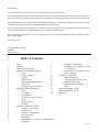
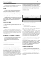
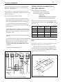
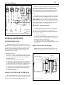
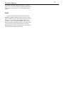
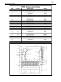
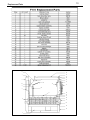
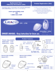
FORCED AIR WOOD FURNACE
Box 3637, Smithers, BC V0J 2N0
F75R and F101
INSTALLATION AND OPERATION INSTRUCTION MANUAL
PLEASE
KEEP THESE
INSTRUCTIONS
FOR FUTURE
REFERENCE
Operation
Maintenance
Installation
furnace/jc/june96
Dear Customer,
You have purchased one of the finest wood burning heating systems in North America.
You will find that your Ardent Energy furnace will operate much differently than the old fashioned fireboxes of the past. You will
experience a new level of heating comfort and convenience, with greater control, longer burn times and reduced creosote deposits.
Please take the time to become familiar with your Ardent Energy heating system. Study your manual carefully before you begin
installing or operating your furnace. Keep the manual handy for future reference.
If you would like to add optional equipment to your furnace, make sure that you have the serial number of your furnace when you
visit your Ardent Energy dealer. This will help us give you prompt and accurate service.
We at Ardent Energy congratulate you on your choice of wood furnaces, and are confident that you have purchased a product
that is simply, the best.
Ardent Energy Inc
J G (Hans) Duerichen PEng
President
April 1999 (ver 3)
Table of Contents
3
3
4
4
4
4
3
4
5
5
5
5
5
5
5
6
6
6
6
6
6
6
6
6
7
7
7
Safety
8
Creosote
8
Furnace Specifications
OPERATION INSTRUCTIONS
9
Fuel
Bypass Damper
10
Lighting
10
The First Fire
10
Wall Thermostat Operation
10
Refuelling
10
Operation if the Power Fails
11
FURNACE MAINTENANCE
12
Daily
13
As Needed
14
Ash Removal
If You Have an Oil Add-on
Door
Draft Control
Firebrick
FURNACE INSTALLATION
Chimney Connection
Chimney Size
Chimney Termination
Floor Protection
Duct Work
Installation As A Forced Air Wood Furnace
Assembly
Electrical Components
Installation As An Add-on to An Oil
or Gas Furnace
Installation As An Add-on to An
Electric Furnace
FURNACE OPTIONS
Water Heating Coil
Connecting the Coil to the Tank
Draining and Cleaning
When You Have No Water
Paint
Replacement Parts - F75R
Replacement Parts - F101
Warranty
furnace/jc/june96
3
Furnace Operation
SAFETY
WARNING: If this furnace is not properly installed, a house
fire may result. For your safety, follow the installation
directions. Contact local building or fire officials about
restrictions and installation requirements in your area.
NOTE: We strongly recommend installers to be WETT or
WHERF certified.
To ANYONE using this furnace:
3. DO NOT use gasoline type lantern fuel, kerosene, charcoal
lighter fluid or similar liquids to start or freshen up the fire in
this furnace. Keep all such liquids well away from the furnace
while it is in use.
4. DO keep the furnace door shut at all times when a fire is
burning. Open the door only to load or check the fire.
5. When checking or loading wood into the fire, DO pull open
the bypass lever first, then open the door very slowly.
6. DO keep all combustible materials (firewood, shoes etc.) at
least 18 inches away from the furnace.
These DO's and DO NOT's are for your safety.
1. DO read this instruction manual before lighting your first
fire.
2. DO burn seasoned wood fuel only. DO NOT burn:
- driftwood (salt corrosion is not a warranty item)
- treated wood
- coal
- garbage
- plastic
Also DO NOT use construction scraps (e.g., 2x4 or plywood
scraps) as your only supply of fuel, as you may overheat and
seriously damage the furnace.
7. Do not use a grate or elevate the fire.
CREOSOTE
When wood is burned slowly, it produces tar and other
organic vapours, which combine with expelled moisture to
form creosote. The creosote vapours condense in the relatively cool chimney flue of a slow burning fire. As a result,
creosote residue accumulates in the flue lining. When ignited,
this creosote makes an extremely hot fire.
A chimney fire occurs when creosote in the chimney
ignites, usually when the furnace is turned up high after a
period of low burn.
flue
bypass damper
smoke
shield
heat exchangers
secondary air
secondary air
heat exchanger
water coil
water coil seal
Figure 1: Furnace specifications
down draft
baffle
cross draft
angle
primary
air heat exchanger
primary air
4
Furnace Operation
The chimney should be inspected periodically during the
heating season to see if a creosote build-up has occurred. If a
significant layer of creosote has accumulated (1/4" or more), it
should be removed to reduce the risk of chimney fire. Running
the furnace at maximum with the bypass pulled out for 1 to 2
hours about once a week will minimize creosote buildup.
OPERATION INSTRUCTIONS
The following operating instructions must be followed
carefully for satisfactory operation.
FUEL
In the event of an uncontrolled chimney fire, shut the
bypass damper and turn down the thermostat.
If the chimney fire does not die down, keep watch on the fire
and prepare to vacate the house. If needed, call the fire
department.
NOTE: Establish a routine for the storage of fuel, care of the
furnace and firing technique. Be aware that during mild
weather and low furnace temperatures, more creosote is
deposited and more frequent cleaning is necessary.
HINT: To avoid creosote build-up especially in mild
weather, fill the furnace only part way. Also, well seasoned,
unchopped wood will reduce creosote build-up dramatically.
BYPASS DAMPER
FURNACE SPECIFICATIONS
• Type of fuel
• Combustion system
• Temperature control
• Firebox lining
• Body
• Doors
Wood
Burning
Module No.
Rating......(KW)..
(BTU/hr).
Size.........(mm)...
(in.)........
Weight...............
Fuel
capacity..........
Max. fuel
size.........
Flue
outlet...............
Cold air inlet
size.....
Hot air outlet
size....
- Wood, any species
- Downfeed progressive crossdraft design with a constant
pre-heated secondary air system
- Standard wall thermostat with
manual bi-metallic control during
power failure
- Firebrick: 1 1/4" x 4 1/2" x 9" std.
- Steel: 12 ga, 10 ga & 5/16"
- Constant centre push design
with fibreglass rope seal
F75R
Fuel wood can be of any species. However, ensure that
the wood is well seasoned and kept under cover. Do not burn
any fuel other than wood. Please note that if you use green
wood:
• The amount of wood that you use will increase around
20% when using green compared to dry wood.
• Heat output will be considerably lower and more frequent
fuelling will be necessary.
• Green wood must be cut into smaller pieces to burn
acceptably.
• Creosote formation may increase, especially in warm
weather.
• The fire will most likely have to be started with dry wood
until a good bed of coals is formed.
F101
`1400 - 20000
`1400 - 27000
`5000 - 75000
`5000 - 100000
710W x 965L x 1090 H
760W x 1140L x
1180H
28W x 38L x 43H
30W x 45L x 46 1/2 H
227 kg
295 kg
500 lbs
650 lbs
140 litres
250 litres
5 cu. ft.
9 cu. ft.
250 mm dia. x 500 mm
long
300 mm dia. x 600 mm
long
10" dia. x 20 " long
12" dia. x 24" long
178 mm dia.
203 mm dia.
7" dia.
8" dia.
305 mm x 460 mm
305 mm x 460 mm
12" x 18 "
12" x 18"
445 mm x 680 mm
625 mm x 730 mm
18" x 26 3/4"
24 1/2" x 28 3/4"
When the bypass damper is open (i.e. the bypass rod is
pulled out) combustion will take place within the entire firebox.
Operate the furnace with the bypass damper open only when
you need quick heat.
• When the desired temperature has been reached, push
the bypass rod in.
• Whenever there is a fire burning, the bypass damper
should be open for 30 seconds before you slowly open the
door.
• When you are starting a fire, the bypass damper should
be open to vent away smoke.
• The furnace door must be closed at all times, except
when you are loading fuel or checking the fire.
LIGHTING
Light a fire in the furnace, starting with paper and kindling
only. Never use any flammable liquids. After the fire is lit,
leave the door open a crack for a few minutes. Once a coal bed
is established, add standard cord wood and latch the door
shut.
THE FIRST FIRE
You will experience a slow start-up during the first fire.
The firebricks bricks still contain moisture and take a good hot
fire to eliminate the moisture. While there is moisture in the
bricks, the bricks will be black with smoke deposits. When the
moisture is gone, the bricks will be light coloured. You may
also experience a slight odour during the first few fires. This
odour results from the curing paint and the burn-off of residual
oils.
5
Furnace Operation
WALLTHERMOSTAT OPERATION
FURNACE MAINTENANCE
Set the thermostat to the temperature desired. When the
furnace is warming up a cold room, there will be an initial
temperature overrun, then the temperature will stabilize.
DAILY
REFUELLING
1. Have wood on hand to load the firebox.
2. Open the bypass damper for 30 seconds
3. Open the door slowly. Allow the chimney to draw off
smoke.
4. Load as much wood as you need (right up to the top in
cold weather).
5. Close the door and push in the bypass damper.
NOTE: Do not over- fire the furnace by leaving the door
open. The door should be open only when you light and
check the fire. Operation with the door ajar voids the
warranty.
OPERATION IF THE POWER FAILS
(NOT FOR USE IN FURNACES WITH DOWN FLOW
DUCTING)
1. Open the panel opposite to the air inlet to the wood
section to allow for air circulation.
2. Open all floor registers.
3. Adjust the draft manually by pulling up the chain just
below the damper motor lever, and placing it into the small
damper motor lever
For the first little while, check the chimney and pipe until
experience shows how often cleaning is necessary. About
once a week, run the furnace at maximum with the bypass open
for one to two hours to burn off any creosote in the chimney
and pipes. This should greatly reduce how often you will
need to clean the chimney with a brush.
AS NEEDED
Any creosote build-up in the chimney and pipe over 6 mm
(1/4") should be removed with a brush. Make sure that the
bypass is open before you begin cleaning the chimney.
ASH REMOVAL
Ashes should be removed once they reach a depth of 100
mm (4") maximum. Let the fire burn out. Protect the area in
front of the furnace with a non- combustible material. Shovel
the ashes into a metal container with a tight fitting lid. Other
waste should not be put in this container.
The closed container of ashes should be placed outside
on a non-combustible surface, or on the ground, well away
from any combustible materials. If the ashes are disposed of
by burial or otherwise locally dispersed, they should be
retained in the closed container until you are sure that all of
the cinders have thoroughly cooled.
nuts
pawl
chain guide
• To tighten the door, loosen the bottom nut and tighten the top nut
Figure 3: F75R door adjustment
• To adjust the door in and out,
loosen the top two nuts, adjust
the door. Tighten the nuts.
Figure 2: Operation during a power failure
slot beside the chain guide (see Figure 2)
Do not expect as much heat in cold weather, because duct
work is not designed for heating without a blower. When
power is restored, the damper motor will automatically pull the
chain off the slot and resume normal operation.
• To adjust the door up or
down, loosen the bottom two
nuts, adjust the door. Tighten
the nuts.
NOTE: The chain guide must be "clipped" by installers if
the furnace is installed to heat areas below the furnace.
Figure 4: F101 door adjustment
6
Furnace Installation
IFYOU HAVE AN OILADD-ON
Operate the oil fired unit periodically to ensure that it will
operate satisfactorily when you would like to use it.
DOOR
The door is a unique adjustable centre-push design to
ensure trouble-free, air tight operation for years to come.
When you close the door, there should be a slight resistance.
If there is not, the door needs adjusting. The door pawl (the
catch on the closing mechanism) should be lubricated regularly with a high temperature grease, so the door opens and
closes easily.
If the fibreglass seal shows signs of excessive wear, it may
not seal properly, and cause the furnace to burn hotter than
desired. Replace it with a gasket replacement kit (part #
FDGRK5)
DRAFT CONTROL
Check that the draft control opens and closes freely. If it
does not, open the front left panel and make sure the chain is
not binding.
FIREBRICK
Take care when you are refuelling the furnace to avoid
breaking the brick. If you are burning wood with chunks of ice
and/or snow, do not let the frozen surfaces touch the firebrick.
If any firebrick breaks, replace it immediately in order to avoid
overheating the firebox.
FURNACE INSTALLATION
The F75R and F101 furnaces may be installed as follows:
1. As a stand-alone wood furnace with blower.
2. As an add-on to a stand-alone oil, gas or electric
furnace.
WARNING: These furnaces are not certified for use with an
automatic stoker.
CHIMNEY CONNECTION
The furnace must be installed with a minimum of elbows
and horizontal flue pipe. All horizontal pipe must slope
towards the furnace and be installed with the seam up. The
flue opening on top of the furnace is designed so the pipe will
fit inside the opening. Make all connections in such a way
that any condensation in the flue runs back into the furnace
and not on to the floor. After installing the pipe, each joint
must be secured with 3 screws spaced evenly around the joint.
All single wall stove pipe must have a 460 mm (18") clearance
from all unprotected combustible material.
CAUTION: Under no circumstance is any type of damper or
restriction to be installed in the connection between the
furnace and the chimney. A barometric draft control must be
installed and set at 15 PA (0.06") draft. Removal or noninstallation of the barometric damper voids the warranty.
CHIMNEY SIZE
F75R
178 mm (7") round or
Minimum Flue Height Requirements
elevation
minimum flue height
0 to 2000 ft.
12 ft.
2000 to 3000 ft.
13 ft.
3000 to 4000 ft.
14 ft.
4000 to 6000 ft.
15 ft.
6000 to 8000 ft.
16 ft.
8000 to 10 000 ft.
17 ft.
150mm x 250 mm (6" x 10") inside measure
F101
203 mm (8") round or
150mm x 250 mm (6" x 10") inside measure
NOTE: (In U.S.A. only) You may not connect this furnace to
a chimney flue serving another appliance.
ARDENT Energy furnaces burn very efficiently, resulting
in lower than usual flue gas temperatures. Consequently, we
do not recommend an outside installation of the chimney. If
you have an exterior chimney, certain weather conditions will
cool the chimney below room temperature. When this happens, a back draft and/or creosote formation will occur.
If you are using an existing chimney, it must be inspected
carefully for soundness and to be sure that the preceding
requirements are met.
Note: Optimum performance for these furnaces are obtained
with a draft of between 0.06" and 0.07" (Water Column).
After the installation is complete, the draft must be checked
by your dealer, using a draft gauge while the furnace is
operating at a normal temperature.
CHIMNEYTERMINATION
Chimneys are required to extend at least 915 mm (3 ft.)
above the highest point where they pass through the roof of
the building and at least 610 mm (2 ft.) higher than any portion
within 10 feet.
In some cases, the chimney must be higher than the
minimum for proper draft, due to unfavourable geometry of
surroundings.
7
Furnace Installation
FLOOR PROTECTION
If the floor is combustible, it must be protected by 7 mm
(9/32") or thicker of noncombustible material extending 150 mm
(6") from the sides and rear, and 460 mm (18") from the front.
DUCT WORK
Minimum sizes:
F75R
Return air: 1520 sq. cm (220 sq. in)
Supply air: 1290 sq. cm (200 sq. in)
F101
Return air: 1610 sq. cm (250 sq. in)
Supply air: 1420 sq. cm (220 sq. in)
NOTE: The height of the return air inlet must not be higher
than the warm air registers. A fresh air duct must be installed into the return air system (the recommended size is 8"
diameter).
370 mm (14 1/2")
*** Be sure to provide access
for cleaning the flue pipe ***
125 mm (5")
INSTALLATIONASAFORCEDAIR WOOD
FURNACE
Be sure that you have the following:
• Wood furnace module # F75R or F101
• Blower - Delhi model 210 or Lau DUA10
• Motor - 1/3 HP, 1800 RPM, 110 V 60 Hz
• Connecting duct model FCADB
• Control kit model FCFC1, which includes:
• Thermostat
• Damper motor
• Fan/limit control
• Transformer c/w wiring harness
Plenum pressure
F75R
F101
50 PA (0.20")
5 turns open
3 turns open
75 PA (0.30")
3 turns open
1 1/2 turns open
100 PA (0.40")
1 turn open
0 turns open
NOTE: OBSERVE MINIMUM CLEARANCES! If you need to
reduce the rear clearance, you can cut it to half (50%) if you
protect combustible surfaces with .3mm (.013") or heavier
sheet metal. You must space the sheet metal out 25 mm (1")
by non-combustible spacers (see CSA Installation code
B366 - 1791).
ASSEMBLY
After deciding which side is best for the blower unit,
remove the inlet cover on that side. Use the screws to attach
the connector. The blower sits on top of the connector,
oriented so that the air moves down into the wood furnace
when the blower is on. Make sure that the fan pulley is 203
mm (8") in diameter.
furnace
blower
150 mm (6")
25 mm (1")
After measuring the pressure in the hot air plenum, set the
motor pulley as follows:
Figure 5a: Clearances
ELECTRICAL COMPONENTS
50 mm (2")
50 mm (2"0)
25 mm (1")
return air
2m (6')
plenum
supply duct
Note: If the supply air duct is routed
below furnace level (e.g., in the crawl
space underneath) then the power failure
mode must be deactivated (see page 4).
blower
connecting
duct
furnace
Figure 5b: Duct clearances
1. Install the damper motor using the holes provided
beside the control chain.
2. Install the fan/limit control bracket using the holes
provided on the centre of the front of the furnace. The fan/
limit control can be installed after the hot air plenum is in
place.
3. Install the junction box with the transformer on the top
front corner of the furnace nearest to the blower.
4. Install the room thermostat on a wall centrally located in
the home. It should be located away from the direct heat of
the furnace or a hot air duct.
5. Connect the wiring as shown inFigure 6.
8
Furnace Installation
damper motor
wood section
fan limit control
wood section
room thermostat
wood
supply air
12" x 18" connecting duct
plenum
24 v
white
white
existing oil furnace
black
black
red
wood furnace
blower
Figure 7: Connection to an oil furnace
120 v
3. Check the system air flow as follows:
F igure 6: Wiring diagram for a forced air wood furnace
INSTALLATION ASANADD-ON TOAN OIL
OR GAS FURNACE
Be sure that you have the following:
• Wood furnace module # F75R or F101
• Control kit model FCFC2 or FCFC3, which includes:
• Thermostat
• Damper motor
• 2 fan/limit controls mounted on a bracket
• Junction box
YOU MUST DETERMINE WHETHER THE OIL OR GAS
FURNACE SIZE FALLS WITHIN THE RANGE SHOWN IN
THE FOLLOWING TABLE:
Existing
t y p e
F 7 5 R
furnace
243
3.22
(0.85
G A S
I n p u t
O u t p u t
to
3.79
(0.65
F 1 0 1
O I L
to
litres/hr
1.00USGPH)
to
4.73
litres/hr
to
1.25
USGPH)
20.0
to
27.8
22.2
• Find the air flow by using one of the following formulas:
If you are using metric units:
Q = 24 000 x G
A
Kw
Q = air flow in cu. metres/sec
G = oil input rate in litres/sec.
A = air temperature rise, in °C
BTU/hr)
to
to
The temperature rise (outlet temperature minus the
inlet temperature) should not exceed 30° C (85° F). If so,
increase the blower speed so that the temperature rise is
less than or equal to 30° C (85° F).
Where:
(64,000to98,000
(76,000
• Open all of the registers and install a new filter.
• Measure the temperature rise using two thermometers.
One should be placed through a hole in the hot air plenum.
Run the furnace for 15 minutes then check the temperature,
giving the thermometers enough time to read accurately.
Record both the inlet and the outlet temperatures.
36.0
Kw
123,000
If you are using standard units:
BTU/hr)
Q = 95 000 x G
A
The installation must be performed in series as shown:
(the attachment may be made on either side)
The following checks must be carried out before making
any alterations:
1. Check the size of the furnace. The furnace must match
the specifications of the above table.
2. If the existing furnace is an oil furnace, then check the
size of the nozzle in the oil burner (see table above).
Where:
Q = air flow in cu. ft/min
G = oil input rate in USGPM
A = air temperature rise, in °F
• Check that the duct work and chimney are sound and
that the chimney is of sufficient size (See the chimney
section).
After all checks have been carried out, the wood furnace
may be installed. This task must be performed by a qualified
technician.
9
Furnace Installation
NOTE: The installation must comply with CAS Standard
B365-M87 - "Installation Code For Solid Fuel Burning
Appliances And Equipment."
INSTALLATIONASANADD-ON TOAN
ELECTRIC FURNACE
If any changes are required on the oil furnace, these must
comply with CSA Standard B139 "Installation Code for Oil
Burning Equipment."
Be sure that you have the following:
• Wood furnace module # F75R or F101
• Control kit model FEFC3, which includes:
• Thermostat
• Damper motor
• 2 fan/limit controls mounted on a bracket
• Wiring harness with LV terminal block
Prepare the plenums and connecting ducts:
• The connecting duct between the oil furnace and the
wood furnace must be 305 mm x 460 mm (12" x 18") with
elbows having a minimum inside radius of 150 mm (6").
Your electric furnace blower must be large enough to keep
the furnace equal to or below the following maximum temperature rises:
• Do not connect duct work so that reverse flow is
possible (the cold air return must not be higher than the
warm air outlets).
• After the installation is complete, recheck the air flow as
before. If the air flow is less than before, the blower speed
must be increased to compensate for the pressure drop
through the system.
• For multi-speed blower motors, use the higher speed, if
needed.
• For belt-driven blowers, adjust the pulley diameter on the
motor to give the extra speed required. If necessary, a
larger blower motor may be used if the faster speed
increases the air flow above the rating on the motor
nameplate. HOWEVER, THE BLOWER MUST NOT BE
CHANGED.
Max temp. rise,
F75R °C (°F)
Max temp. rise,
F101 °C (°F)
10 kW
34100
24° (43°)
21° (37°)
15kW
51200
36° (65°)
31° (65°)
20 kW
68200
42° (75°)
41° (73°)
25 kW
85300
42° (75°)
42° (75°)
30 kW
102400
N/A
42° (75°)
35 kW
119400
N/A
42° (75°)
WARNING: If the airflow is too low, your installation will be
unsafe.
NOTE: The temperature rise must be measured between the
inlet and the outlet of the electric furnace only.
blower
limit
*
limit
blower and wood
limit - 250°F
aux. limit
140° F
damper
motor
blower (not used)
wood
thermostat
Output
(BTU/hr)
If the electric furnace is certified for counter-flow operation (upside down) it should be installed according to Figure
5b. Use the connecting duct (part FCADB) in the installation.
Its dimensions are shown in Figure 9.
• Follow the wiring diagram precisely.
oil or gas
thermostat
Furnace Size
432 mm (17")
16 /2
LVT
165 mm
(6 1/2")
16/3
LVT
black
14 /2
BX
white
green
wire supplied with
harness
wire supplied by
customer
*
jumper
removed
305 mm
(12")
low voltage
terminal block
24 V
source
460 mm
(18")
to furnace common
start relay from 24 V
transformer
110 V
source
to
blower
motor
Figure 9: Connecting duct (part # FJADB)
Figure 8: Wiring diagram for adding on to oil or gas (control kit #FEFC2)
432 mm (17")
10
Furnace Options
aux. limit
140° F
blower & wood
limit 250° F
limit
limit
damper
motor
blower (not used)
wood
thermostat
blower
electric,
oil or gas
thermostat
When you connect the piping to the range boiler you must
strictly follow the diagram in figure 11. The two shut-off
valves must be no smaller than 3/4" GATE valves. Make
certain that the PRV (Watts 3L) and the P&TRV (Watts 100
XL) are installed in their respective locations and not vice
versa.
16 / 3
The maximum pressure setting is 38 kPa (150 psi). Do not
use less than 3/4" diameter standard pipe between the range
boiler and the furnace. The orientation of the pipe must be
slightly uphill from the coil outlet to the upper connection at
the tank. If you do no do this, vapour lock will occur, and the
water will not circulate. The minimum capacity of the range
boiler should be 100 litres (26 U.S. gallons).
16 / 2
white
black
low voltage terminal block
DRAINING AND CLEANING
16 / 4 LVT
W
to electric
furnace relay
C
common
from 24V
transformer
G
to blower
relay
R
24 V
source
wire supplied with
harness
wire supplied by
customer
Cleaning should not normally be necessary unless the
water tends to cause deposits. If the heating efficiency
decreases noticeably, the heating coil should be inspected,
and if necessary, cleaned.
Figure 10: Wiring diagram for typical wood - electric combination (control kit # FEFC3)
FURNACE OPTIONS
WATER HEATING COIL
ARDENT Energy furnaces are designed to heat your
domestic hot water during the heating season. The F75R and
F101 can accept 1 or two coils (1 per side). When you install
the water coil (part FCSHW4) it replaces all but one of the
firebricks on the side it is located. Please read all of the
instructions before you begin.
To install the water coil:
1. Remove the back shroud on the furnace by removing
the screws. Using a good punch and hammer, punch out
the two knockouts on the side where you would like to
install the water coil.
2. Remove all of the firebrick from that side.
3. Punch out the two knockouts at the rear of the firebox.
4. Remove the baffle plate inside the rear of the firebox.
5. Position the water coil in the firebox, in the place where
the firebrick was removed. The pipe must face the fire.
6. Install the ceramic gaskets and plates on the outside of
the firebox (not on the outside of the shroud) using the
provided drill and tap screws.
7. Replace the shroud.
1. Let the furnace cool down.
2. Close the valves between the range boiler and the coil.
3. Open the drain valves and drain the water from the coil.
4. Disconnect the coil at the unions.
5. Clean the coil using a drain cleaning "snake."
6. Connect the piping, close the drain and open the valves
to the boiler.
WHEN YOU HAVE NO WATER
Do not operate your furnace with a dry water coil. The
excess heat will damage the water coil. If you have no water
insulate this
connecting pipe
P & TRV (Watts 100XL)
1/4" gate valve
hot
water
out
cold water in
PRV (Watts 3L)
1/4" union
dip
tube
furnace
CONNECTING THE COILTO THE TANK
range boiler
(uninsulated)
to drain
We recommend that you use the "two tank" system. The
first tank or "range boiler" must remain uninsulated to dissipate any excess heat generated by the hot water coil.
Figure 11: Connection to hot water heater
existing water
heater
to
drain
Furnace Options
for circulation, disconnect and remove the coil. To seal the
holes, use two 25 mm (1") diameter standard washers per hole,
and use a 19 mm x 25 mm (3/4" x 1") bolt to hold the washers
together.
PAINT
You may touch up the face of the furnace with STOVE
BRIGHT Satin Black 1990 high temperature paint. The correct
paint is available from your dealer. When you paint the face of
the furnace, cover the area surrounding the furnace with
newspaper. Follow the directions outlined on the spray can.
DO NOT attempt to paint while the furnace is still warm. Keep
the spray can away from any source of heat or open flame.
Ensure that there is adequate ventilation in the room, from the
time you start painting until the paint is dry.
11
12
Replacement Parts
F75R Replacement Parts
ITEM
QTY/UNIT
DESCRIPTION
PART#
1
2
3
4
5
6
8
9
10
11
12
13
14
15
16
17
18
19
20
21
22
23
24
25
26
27
28
29
1
1
1
1
1
2
1
1
1
1
1
1
2
1
30"
1
1
1
2
60"
1
1 KIT
1
1
1
1
1
1
rear top shroud
back shroud liner assy
bypass damper assy
bypass lever
flame deflector
outside fin
water coil (optional)
side shroud door
bypass assembly
Scandinavian baffle
bypass frame bottom
baffle down draft
smoke shield assembly
door liner
cross draft angle assy
side shroud assy
ball chain
front top shroud (T-nut)
bypass bar
door closure pawl
hug lock nut
gasket replacement kit
door final assembly
front side shroud
prim. air heat exhanger
air inlet cast
butterfly "D" assembly
lower front shroud
A399P
A414W
A237W
A239W
A533
A407
FCSHW4
A398
A272
AAPO14
A238
A532
A129W
A302
A725LW/RW
A413W
R6110
A400
A391
A309
R1442
FDGRK5
A317-75
A401
A390W
A913
A720W
A717
17
1
18
19
20
2
10
3
21
11
22
4
14
12
5
6
13
16
15
23
24
25
26
27
28
8
29
9
13
Replacement Parts
8
25
13
1
14
26
2
15
9
16
10
27
12
17
3
28
4
11
29
18
19
20
6
21
22
23
24
7
F75R & F101 FURNACE WARRANTY
FIVE YEAR LIMITED WARRANTY
Ardent Energy Inc warrants the F75R and F101 furnaces against defects in material and workmanship
for a period of five years from the date received, with the exception of items listed hereafter in the "Exclusions"
section.
Ardent Energy Inc, at its option, will replace, repair or cause to be repaired any part found to be defective upon inspection by an authorized Ardent Energy Inc representative.
EXCLUSIONS
1. Repairs or replacement of part or the entire appliance necessitated by use of the furnace other than
for normal home use, as directed by the instruction manual.
2. Repairs or replacements necessitated by vandalism, neglect, abuse or failure to adequately service
the appliance, as stated in the instruction manual.
3. Repairs or replacements necessitated by work or service not authorized by Ardent Energy Inc
equipment and accessories not manufactured by Ardent Energy are warranted only to the extent of
the original manufacturer’s warranty.
4. Replacement of gaskets and firebrick.
5. Repairs necessitated by excessive chimney draft.
LIMITATIONS
1. All items found to be defective will be replaced or repaired upon return of the defective part to an
authorized Ardent Energy Inc dealer.
2. Any furnace or part thereof that is replaced or serviced during the five year warranty period, will
be warranted under the terms of that particular limited warranty for a period not exceeding the
remaining term of the original limited warranty, or six months, whichever is longer.
3. This warranty is transferable. However, proof of date of purchase is required before service or
replacement of any defective part is performed.
4. This Limited Warranty does not apply to damage to the furnace or part thereof, while in transit.
Any claim of such must be directed to the common carrier.
5. If the installation does not conform to local building or fire codes, or in their absence, the installation requirements in the instruction manual, any claims are not valid and will not be processed.
6. Any shipping charges incurred during a warranty claim will be borne by the furnace owner.
7. The remedies set forth herein are exclusive, and the liability of Ardent Energy Inc with respect to
any contract, tort, under any warranty or otherwise shall not exceed the price of the equipment or
part on which such liability is based.