1
LTH125
Owner’s Manual
SAFETY RULES
Safe Operation Practices for Ride-On Mowers
IMPORTANT: THIS CUTTING MACHINE IS CAPABLE OF AMPUTATING HANDS AND FEET AND THROWING OBJECTS.
FAILURE TO OBSERVE THE FOLLOWING SAFETY INSTRUCTIONS COULD RESULT IN SERIOUS INJURY OR DEATH.
I.
GENERAL OPERATION
III. CHILDREN
•
Read, understand, and follow all instructions in the manual
and on the machine before starting.
Only allow responsible adults, who are familiar with the
instructions, to operate the machine.
Clear the area of objects such as rocks, toys, wire, etc.,
which could be picked up and thrown by the blade.
Be sure the area is clear of other people before mowing. Stop
machine if anyone enters the area.
Never carry passengers.
Do not mow in reverse unless absolutely necessary. Always
look down and behind before and while backing.
Be aware of the mower discharge direction and do not point
it at anyone. Do not operate the mower without either the
entire grass catcher or the guard in place.
Slow down before turning.
Never leave a running machine unattended. Always turn off
blades, set parking brake, stop engine, and remove keys
before dismounting.
Turn off blades when not mowing.
Stop engine before removing grass catcher or unclogging
chute.
Mow only in daylight or good artificial light.
Do not operate the machine while under the influence of
alcohol or drugs.
Watch for traffic when operating near or crossing roadways.
Use extra care when loading or unloading the machine into
a trailer or truck.
Tragic accidents can occur if the operator is not alert to the
presence of children. Children are often attracted to the machine
and the mowing activity. Never assume that children will remain
where you last saw them.
•
•
•
•
•
•
•
•
•
•
•
•
•
•
•
•
•
•
•
•
Keep children out of the mowing area and under the watchful
care of another responsible adult.
Be alert and turn machine off if children enter the area.
Before and when backing, look behind and down for small
children.
Never carry children. They may fall off and be seriously
injured or interfere with safe machine operation.
Never allow children to operate the machine.
Use extra care when approaching blind corners, shrubs,
trees, or other objects that may obscure vision.
IV. SERVICE
•
•
•
II. SLOPE OPERATION
•
Slopes are a major factor related to loss-of-control and tipover
accidents, which can result in severe injury or death. All slopes
require extra caution. If you cannot back up the slope or if you feel
uneasy on it, do not mow it.
•
DO:
•
Mow up and down slopes, not across.
•
Remove obstacles such as rocks, tree limbs, etc.
•
Watch for holes, ruts, or bumps. Uneven terrain could
overturn the machine. Tall grass can hide obstacles.
•
Use slow speed. Choose a low gear so that you will not have
to stop or shift while on the slope.
•
Follow the manufacturer’s recommendations for wheel
weights or counterweights to improve stability.
•
Use extra care with grass catchers or other attachments.
These can change the stability of the machine.
•
Keep all movement on the slopes slow and gradual. Do not
make sudden changes in speed or direction.
•
Avoid starting or stopping on a slope. If tires lose traction,
disengage the blades and proceed slowly straight down the
slope.
•
•
•
•
•
Use extra care in handling gasoline and other fuels. They are
flammable and vapors are explosive.
- Use only an approved container.
- Never remove gas cap or add fuel with the engine
running. Allow engine to cool before refueling. Do not
smoke.
- Never refuel the machine indoors.
- Never store the machine or fuel container inside where
there is an open flame, such as a water heater.
Never run a machine inside a closed area.
Keep nuts and bolts, especially blade attachment bolts, tight
and keep equipment in good condition.
Never tamper with safety devices. Check their proper
operation regularly.
Keep machine free of grass, leaves, or other debris build-up.
Clean oil or fuel spillage. Allow machine to cool before
storing.
Stop and inspect the equipment if you strike an object.
Repair, if necessary, before restarting.
Never make adjustments or repairs with the engine running.
Grass catcher components are subject to wear, damage, and
deterioration, which could expose moving parts or allow
objects to be thrown. Frequently check components and
replace with manufacturer's recommended parts, when necessary.
Mower blades are sharp and can cut. Wrap the blade(s) or
wear gloves, and use extra caution when servicing them.
Check brake operation frequently. Adjust and service as
required.
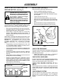
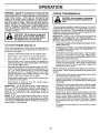
Look for this symbol to point out important safety precautions. It means
CAUTION!!! BECOME ALERT!!! YOUR
SAFETY IS INVOLVED.
DO NOT:
•
Do not turn on slopes unless necessary, and then, turn slowly
and gradually downhill, if possible.
•
Do not mow near drop-offs, ditches, or embankments. The
mower could suddenly turn over if a wheel is over the edge
of a cliff or ditch, or if an edge caves in.
•
Do not mow on wet grass. Reduced traction could cause
sliding.
•
Do not try to stabilize the machine by putting your foot on the
ground.
•
Do not use grass catcher on steep slopes.
CAUTION: Always disconnect spark
plug wire and place wire where it cannot
contact spark plug in order to prevent
accidental starting when setting up,
transporting, adjusting or making
repairs.
2
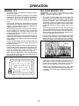
PRODUCT SPECIFICATIONS
CONGRATULATIONS on your purchase of a new tractor. It has been designed, engineered and manufactured
to give you the best possible dependability and performance.
Should you experience any problem you cannot easily
remedy, please contact your nearest authorized service
center. We have competent, well-trained technicians and
the proper tools to service or repair this tractor.
Please read and retain this manual. The instructions will
enable you to assemble and maintain your tractor properly. Always observe the "SAFETY RULES".
MODEL
NUMBER
LTH125
SERIAL
NUMBER ____________________________________
DATE OF PURCHASE __________________________
THE MODEL AND SERIAL NUMBERS WILL BE FOUND
ON A PLATE UNDER THE SEAT.
•
Follow a regular schedule in maintaining, caring for and
using your tractor.
•
Follow the instructions under "Customer Responsibilities" and "Storage" sections of this manual.
GASOLINE CAPACITY
AND TYPE:
2 GALLONS
UNLEADED REGULAR
OIL TYPE (API-SF/SG):
SAE 30 (above 32°F)
SAE 5W-30 (below 32°F)
OIL CAPACITY:
3.0 PINTS
SPARK PLUG:
(GAP: .030”)
CHAMPION RJ19LM
VALVE CLEARANCE:
INTAKE:
.005” - .007”
EXHAUST: .009” - .011”
GROUND SPEED (MPH):
FORWARD: 5.0
REVERSE: 2.4
TIRE PRESSURE:
FRONT: 14 PSI
REAR: 12 PSI
CHARGING SYSTEM:
3 AMPS BATTERY
BLADE BOLT TORQUE:
30-35 FT. LBS.
WARNING: This unit is equipped with an internal combustion engine and should not be used on or near any unimproved forest-covered, brush-covered or grass-covered
land unless the engine’s exhaust system is equipped with
a spark arrester meeting applicable local or state laws (if
any). If a spark arrester is used, it should be maintained in
effective working order by the operator.
A spark arrester for the muffler is available through your
nearest authorized service center/department (See REPAIR PARTS section of this manual).
CUSTOMER RESPONSIBILITIES
Read and observe the safety rules.
12.5
5 AMPS HEADLIGHTS
YOU SHOULD RECORD BOTH SERIAL NUMBER AND
DATE OF PURCHASE AND KEEP IN A SAFE PLACE
FOR FUTURE REFERENCE.
•
HORSEPOWER:
3
TABLE OF CONTENTS
SAFETY RULES............................................................ 2
PRODUCT SPECIFICATIONS ...................................... 3
CUSTOMER RESPONSIBILITIES ..................... 3, 15-19
ASSEMBLY ................................................................ 6-9
OPERATION ........................................................... 10-14
MAINTENANCE SCHEDULE ..................................... 15
SERVICE AND ADJUSTMENTS ........................... 20-25
STORAGE ................................................................... 26
TROUBLESHOOTING ........................................... 27-28
REPAIR PARTS - TRACTOR ................................ 30-47
WARRANTY ................................................................ 51
INDEX
A
Adjustments:
Brake ........................................... 22
Carburetor ................................... 25
Mower:
Front-To-Back ........................ 21
Side-To-Side .......................... 21
Throttle Control Cable ...... ...........25
Air Filter, Engine ................................. 18
Assembly ........................................... 6-9
B
Battery:
Charging ....................................... 7
Cleaning ...................................... 17
Installation ..................................... 8
Levels ....................................... 7,17
Preparation ................................... 7
Starting with Weak Battery .......... 24
Storage ....................................... 26
Terminals .................................... 17
Belt:
Motion Drive
Removal/Replacement ........... 22
Mower Blade Drive
Removal/Replacement ........... 21
Blade:
Sharpening .................................. 16
Replacement ............................... 16
Brake Adjustment ............................... 22
E
Electrical:
Interlocks and Relays .................. 24
Schematic ................................... 29
Wiring Diagram ........................... 30
Engine:
Air Filter ....................................... 18
Cooling Fins ................................ 19
Oil Change .................................. 18
Oil Level ................................. 12,18
Oil Type ....................................... 18
Preparation ................................. 12
Starting ........................................ 13
Storage ....................................... 26
F
Filter:
Air Filter ....................................... 18
Fuel ............................................. 19
Fuel:
Type ............................................ 12
Storage ....................................... 26
Fuse ................................................... 24
H
Hood Removal/Installation ................. 24
L
Leveling Mower Deck ......................... 21
Lubrication Chart ................................ 15
C
Carburetor Adjustment ....................... 25
Controls, Tractor ................................ 10
Customer Responsibilities ............. 15-19
Engine:
Air Filter ................................... 18
Battery ..................................... 17
Engine Oil ............................... 18
Fuel Filter ................................ 19
Spark Plugs ............................. 19
Tractor:
Blade ....................................... 16
Lubrication Chart ..................... 15
Maintenance Schedule ........... 15
Tire Care ......................... 7,16,23
Cutting Height, Mower ........................ 11
M
Maintenance Schedule ....................... 15
Mower:
Adjustment, Front-to-Back .......... 21
Adjustment, Side-to-Side ............ 21
Blade Sharpening ....................... 16
Blade Replacement ..................... 16
Cutting Height ............................. 11
Installation ................................... 20
Operation .................................... 12
Removal ...................................... 20
Mowing Tips ....................................... 14
Muffler ................................................ 19
Mulcher Plate ....................................... 9
O
Oil:
Cold Weather Conditions ....... 12,18
Engine ......................................... 18
Storage ....................................... 26
4
Operation ......... .............................10-14
Operating Mower ................................12
P
Parking Brake ..................................... 11
Parts Bag ............................................. 5
Parts, Replacement/Repair ........... 30-47
Product Specifications...........................3
R
Repair Parts .................................. 30-47
S
Safety Rules ......................................... 2
Seat ...................................................... 7
Service and Adjustments .............. 20-25
Carburetor ................................... 25
Fuse ............................................ 24
Hood Removal/Installation .......... 24
Motion Drive Belt
Removal/Replacement ........... 22
Mower Blade Drive Belt
Removal/Replacement ........... 21
Mower Adjustment:
Front- to-Back ........................ 21
Side-to-Side ........................... 21
Mower Removal .......................... 20
Tire Care ............................. 7,16,23
Slope Guide Sheet ............................. 50
Spark Plugs ........................................ 19
Specifications ....................................... 3
Starting the Engine ............................. 13
Steering Wheel ................................ 6,23
Stopping the Tractor ........................... 11
Storage .............................................. .26
T
Throttle Control Cable Adjustment ..... 25
Tires...................................................7,16,23
Transaxle ........................................... 17
Transmission:
Purge .......................................... 13
Trouble Shooting Chart ..................27-28
W
Warranty ............................................. 51
Wiring Diagram .................................. 30
Wiring Schematic ............................... 29
CONTENTS OF HARDWARE PACK
5
ASSEMBLY
Your new tractor has been assembled at the factory with exception of those parts left unassembled for shipping purposes.
To ensure safe and proper operation of your tractor, all parts and hardware you assemble must be tightened securely. Use
the correct tools as necessary to insure proper tightness.
TOOLS REQUIRED FOR ASSEMBLY
INSERT
A socket wrench set will make assembly easier. Standard
wrench sizes are listed.
(1) 3/4" socket w/drive ratchet
(2) 7/16" wrenches
Phillips Screwdriver
(1) 1/2" wrench
Utility knife
(1) 9/16" wrench
Tire pressure gauge
3/8-24 LOCKNUT
LARGE FLAT
WASHER
STEERING
WHEEL
When right and left hand is mentioned in this manual, it
means when you are in the operating position (seated
behind the steering wheel).
STEERING
SLEEVE
RETAINER CLIPS
(TAB TO OUTSIDE)
STEERING
WHEEL HUB
ADAPTER
TO REMOVE TRACTOR FROM CARTON
UNPACK CARTON
•
•
•
ADJUSTABLE
EXTENSION SHAFT
Remove all accessible loose parts and parts cartons
from carton (See page 5).
Cut along lines on carton, from top to bottom, all four
corners of carton and lay panels flat.
Check for any additional loose parts or cartons and
remove.
5/16 HEX BOLT
STEERING SLEEVE
BEFORE ROLLING TRACTOR OFF SKID
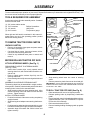
ATTACH STEERING WHEEL (See Fig. 1)
5/16 LOCKNUT
PREASSEMBLE SLEEVE TO STEERING WHEEL
(See Fig. 1 Inset)
• Install sleeve retainer clips, evenly spaced around
steering wheel hub, with formed tabs toward the outside of hub.
• Press or lightly tap the retainer clips fully onto the
steering wheel hub.
• Press steering sleeve fully onto steering wheel hub and
clips.
LOWER
STEERING
SHAFT
FIG. 1
•
•
ASSEMBLE ADJUSTABLE EXTENSION SHAFT
The steering wheel may be assembled in a high, medium,
or low position. Position is determined by which of the three
mounting holes is used in the extension shaft.
• Slide extension shaft onto lower steering shaft. Align
desired mounting holes and install 5/16 hex bolt and
locknut. Tighten securely.
Snap steering wheel insert into center of steering
wheel.
Remove protective plastic from tractor hood and grill.
IMPORTANT: CHECK FOR AND REMOVE ANY STAPLES
IN SKID THAT MAY PUNCTURE TIRES WHERE TRACTOR
IS TO ROLL OFF SKID.
TO ROLL TRACTOR OFF SKID (See Fig. 8)
•
•
INSTALL STEERING WHEEL
• Position front wheels of the tractor so they are pointing
straight forward.
• Slide steering wheel adapter onto steering shaft extension.
• Position steering wheel and sleeve assembly so cross
bars are horizontal (left to right) and slide onto adapter.
• Assemble large flat washer and 3/8-24 locknut and
tighten securely.
•
•
•
6
Raise attachment lift lever to its highest position.
Release parking brake by depressing clutch/brake
pedal.
Place freewheel control in freewheel position to disengage transmission. (See "TO TRANSPORT" in Operation section of this manual).
Roll tractor backwards off skid.
Remove banding holding discharge guard up against
tractor.
ASSEMBLY
HOW TO SET UP YOUR TRACTOR
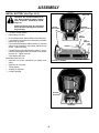
INSTALL SEAT (See Fig. 3)
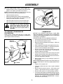
PREPARE BATTERY (See Fig. 2)
Adjust seat before tightening adjustment knob.
• Remove cardboard packing on seat pan.
• Place seat on pan and assemble shoulder bolt.
• Assemble adjustment knob and flat washer loosely.
Do not tighten.
• Tighten shoulder bolt securely.
• Lower seat into operating position and sit on seat.
• Slide seat until a comfortable position is reached which
allows you to press clutch/brake pedal all the way
down.
• Get off seat without moving its adjusted position.
• Raise seat and tighten adjustment knob securely.
CAUTION: Wear eye and face shield.
Wash hands or clothing immediately if
accidentally in contact with battery acid.
Do not smoke. Fumes from charged
battery acid are explosive.
Read the instructions included with the
battery vent caps. Always wear gloves,
clothing and goggles to protect your
hands, skin and eyes.
Your tractor has a battery charging system which is sufficient for normal use. However, periodic charging of the
battery with an automotive charger will extend its life.
• See instructions packed with vent caps in parts bag.
• Fill battery with acid. Fill each cell until it reaches the
bottom of the vent wells. Do not overfill.
• Allow battery to stand and settle for at least thirty
minutes. After standing, check the level of acid. If
below the vent wells, add more acid until the correct
level is reached.
While battery is standing (after adding acid) and later, while
battery is being charged, continue with assembly of tractor.
SEAT
SEAT PAN
SHOULDER
BOLT
IMPORTANT: TO MAXIMIZE THE LIFE OF YOUR
BATTERY, IT IS NECESSARY THAT THE BATTERY BE
C H A R G E D BE F O R E U S E . F A I L U R E T O C H A R GE
BATTERY CAN RESULT IN A SHORTENED BATTERY
LIFE.
•
•
•
•
•
•
FLAT WASHER
Charge battery at a rate of 6 amperes for 1 hour. Use
a 12 volt battery charger. Observe all safety precautions required for battery charging.
Check the acid level after the battery is charged. If the
acid has fallen below the correct level, add distilled or
iron free water.
Install the vent caps to cover the vent wells. Wash the
top of the battery with water to remove any acid, then
wipe dry.
Check battery case for leakage to make sure that no
damage has occurred in handling.
Dispose of excess battery acid. Neutralize acid for
disposal by adding it to 2 gallons of water in a five gallon
plastic container. Stir with a wooden or plastic paddle
while adding baking soda until the addition of more
soda causes no more foaming.
Follow instructions on how to install battery.
CUT AWAY VIEW
ADJUSTMENT KNOB
FIG. 3
CHECK TIRE PRESSURE
The tires on your tractor were overinflated at the factory for
shipping purposes. Correct tire pressure is important for
best cutting performance.
• Reduce tire pressure to PSI shown in "PRODUCT
SPECIFICATIONS" on page 3 of this manual.
CHECK DECK LEVELNESS
For best cutting results, mower housing should be properly
leveled. See "TO LEVEL MOWER HOUSING" in the
Service and Adjustments section of this manual.
CHECK FOR PROPER POSITION OF ALL
BELTS
VENT CAP
See the figures that are shown for replacing motion and
mower blade drive belts in the Service and Adjustments
section of this manual. Verify that the belts are routed
correctly.
VENT WELL
BATTERY
CELL ACID
LEVEL
CHECK BRAKE SYSTEM
After you learn how to operate your tractor, check to see
that the brake is properly adjusted. See "TO ADJUST
BRAKE" in the Service and Adjustments section of this
manual.
FIG. 2
7
ASSEMBLY
INSTALL BATTERY (See Figs. 4 & 5)
BATTERY
BOX DOOR
CAUTION: Do not short battery terminals. Before installing battery, remove
metal bracelets, wristwatch bands,
rings, etc.
Positive terminal must be connected
first to prevent sparking from accidental grounding.
POSITIVE
(RED) CABLE
Lift seat to raised position.
Open battery box door.
Be sure battery drain tube is attached to battery box.
Lower battery into battery box with battery terminals
toward front of tractor.
• First connect RED battery cable to positive (+) terminal
with hex bolt, flat washer, lock washer and hex nut as
shown. Tighten securely.
• Connect BLACK grounding cable to negative (-) terminal with remaining hex bolt, flat washer, lock washer
and hex nut. Tighten securely.
• Close battery box door.
Open battery box door for:
• Inspection for secure connections (to tighten hardware).
• Inspection for corrosion.
• Testing battery.
• Jumping (if required).
• Periodic charging .
NEGATIVE
(BLACK) CABLE
•
•
•
•
LOCK
WASHER
FLAT
WASHER
HEX
BOLT
HEX NUT
NEGATIVE (-) TERMINAL
POSITIVE (+) TERMINAL
FIG. 4
BATTERY
BOX DOOR
VENT CAPS
FIG. 5
8
ASSEMBLY
INSTALL MULCHER PLATE (See Figs.6 & 7)
DEFLECTOR
SHIELD
•
Install two latch hooks to mulcher plate using screw,
washer, lock washer, and weld nut as shown.
NOTE: Pre-assemble weld nut to latch hook by inserting
weld nut from the top with hook pointing down.
• Tighten hardware securely.
• Raise and hold deflector shield in upright position.
• Place front of mulcher plate over front of mower deck
opening and slide into place, as shown.
• Hook front latch into hole on front of mower deck.
• Hook rear latch into hole on back of mower deck.
CAUTION: Do not remove discharge
guard from mower. Raise and hold
guard when attaching mulcher plate
and allow it to rest on plate while in
operation.
LATCH
HOOKS
FIG. 7
✓CHECKLIST
TO CONVERT TO BAGGING OR
DISCHARGING
BEFORE YOU OPERATE AND ENJOY YOUR NEW
TRACTOR, WE WISH TO ASSURE THAT YOU RECEIVE
THE BEST PERFORMANCE AND SATISFACTION FROM
THIS QUALITY PRODUCT.
PLEASE REVIEW THE FOLLOWING CHECKLIST:
✓ All assembly instructions have been completed.
✓ No remaining loose parts in carton.
✓ Battery is properly prepared and charged. (Minimum
1 hour at 6 amps).
✓ Seat is adjusted comfortably and tightened securely.
✓ All tires are properly inflated. (For shipping purposes,
the tires were overinflated at the factory).
✓ Be sure mower deck is properly leveled side-to-side/
front-to-rear for best cutting results. (Tires must be
properly inflated for leveling).
✓ Check mower and drive belts. Be sure they are routed
properly around pulleys and inside all belt keepers.
✓ Check wiring. See that all connections are still secure
and wires are properly clamped.
✓ Before driving tractor, be sure freewheel control is in
drive position.
WHILE LEARNING HOW TO USE YOUR TRACTOR, PAY
EXTRA ATTENTION TO THE FOLLOWING IMPORTANT
ITEMS:
✓ Engine oil is at proper level.
✓ Fuel tank is filled with fresh, clean, regular unleaded
gasoline.
✓ Become familiar with all controls - their location and
function. Operate them before you start the engine.
✓ Be sure brake system is in safe operating condition.
✓ It is important to purge the transmission before operating your tractor for the first time. Follow proper starting
and transmission purging instructions (See "TO START
ENGINE" and "PURGE TRANSMISSION" in Operation section of this manual).
Simply remove mulcher plate and store in a safe place.
Your mower is now ready for discharging or installation of
optional grass catcher accessory.
HOOK POINTS
DOWN
WELD NUT
FROM THE TOP
WELD
NUT
LOCK
WASHER
SCREW
LATCH
HOOK
LATCH
HOOK
LOCK
WASHER
WASHER
WELD
NUT
WASHER
MULCHER
PLATE
SCREW
FIG. 6
9
OPERATION
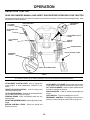
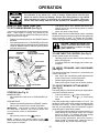
KNOW YOUR TRACTOR
READ THIS OWNER'S MANUAL AND SAFETY RULES BEFORE OPERATING YOUR TRACTOR
Compare the illustrations with your tractor to familiarize yourself with the locations of various controls and adjustments. Save
this manual for future reference.
LIGHT SWITCH
POSITION
THROTTLE/CHOKE
CONTROL
LIFT LEVER
PLUNGER
ATTACHMENT LIFT
LEVER
ATTACHMENT CLUTCH
LEVER
CLUTCH/BRAKE
PEDAL
IGNITION
SWITCH
PARKING BRAKE
MOTION CONTROL LEVER
FREEWHEEL
CONTROL
HEIGHT ADJUSTMENT KNOB
FIG. 8
Our tractors conform to the safety standards of the American National Standards Institute.
ATTACHMENT CLUTCH LEVER: Used to engage the
mower blades, or other attachments mounted to your
tractor.
THROTTLE/CHOKE CONTROL: Used for starting and
controlling engine speed.
CLUTCH/BRAKE PEDAL: Used for declutching and braking the tractor and starting the engine.
PARKING BRAKE: Locks clutch/brake pedal into the
brake position.
HEIGHT ADJUSTMENT KNOB - Used to adjust the mower
height.
MOTION CONTROL LEVER: Selects the speed and
direction of tractor.
ATTACHMENT LIFT LEVER: Used to raise and lower the
mower deck or other attachments mounted to your tractor.
LIFT LEVER PLUNGER: Used to release attachment lift
lever when changing its position.
IGNITION SWITCH: Used for starting and stopping the
engine.
LIGHT SWITCH: Turns the headlights on and off.
FREEWHEEL CONTROL: Disengages transmission for
pushing or slowly towing the tractor with the engine off.
10
OPERATION
The operation of any tractor can result in foreign objects thrown into the eyes,
which can result in severe eye damage. Always wear safety glasses or eye shields
while operating your tractor or performing any adjustments or repairs. We recommend a wide vision safety mask for over the spectacles or standard safety glasses.
HOW TO USE YOUR TRACTOR
•
Turn ignition key to “OFF” position and remove key.
Always remove key when leaving tractor to prevent
unauthorized use.
• Never use choke to stop engine.
NOTE: Under certain conditions when tractor is standing
idle with the engine running, hot engine exhaust gases may
cause “browning” of grass. To eliminate this possibility,
always stop engine when stopping tractor on grass areas.
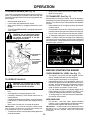
TO SET PARKING BRAKE (See Fig. 9)
Your tractor is equipped with an operator presence sensing
switch. When engine is running, any attempt by the
operator to leave the seat without first setting the parking
brake will shut off the engine.
• Depress clutch/brake pedal into full "BRAKE" position
and hold.
• Place parking brake lever in "ENGAGED" position and
release pressure from clutch/brake pedal. Pedal should
remain in "BRAKE" position. Make sure parking brake
will hold tractor secure.
"ENGAGED"
POSITION
CAUTION: Always stop tractor completely, as described above, before leaving the operator’s position; to empty
grass catcher, etc.
ATTACHMENT
CLUTCH LEVER
"DISENGAGED" POSITION
TO USE THROTTLE CONTROL (See Fig. 9)
Always operate engine at full throttle.
• Operating engine at less than full throttle reduces the
battery charging rate.
• Full throttle offers the best bagging and mower performance.
THROTTLE/CHOKE
CONTROL LEVER
IGNITION KEY
PARKING BRAKE
"ENGAGED"
POSITION
TO MOVE FORWARD AND BACKWARD
(See Fig. 9)
"DISENGAGED"
POSITION
"BRAKE"
POSITION
The direction and speed of movement is controlled by the
motion control lever.
• Start tractor with clutch/brake pedal depressed and
motion control lever in neutral (N) position.
• Release parking brake and clutch/pedal.
• Slowly move motion control lever to desired position.
MOTION CONTROL
LEVER
CLUTCH/BRAKE
PEDAL "DRIVE" POSITION
HEIGHT ADJUSTMENT
KNOB
TO ADJUST MOWER CUTTING HEIGHT
(See Fig. 9)
FIG. 9
The cutting height is controlled by turning the height adjustment knob in desired direction.
• Turn knob clockwise ( ) to raise cutting height.
• Turn knob counterclockwise (
) to lower cutting
height.
The cutting height range is approximately 1-1/2" to 4". The
heights are measured from the ground to the blade tip with
the engine not running. These heights are approximate
and may vary depending upon soil conditions, height of
grass and types of grass being mowed.
• The average lawn should be cut to approximately 2-1/2
inches during the cool season and to over 3 inches
during hot months. For healthier and better looking
lawns, mow often and after moderate growth.
• For best cutting performance, grass over 6 inches in
height should be mowed twice. Make the first cut
relatively high; the second to desired height.
STOPPING (See Fig. 9)
MOWER BLADES • Move attachment clutch lever to “DISENGAGED” position.
GROUND DRIVE • Depress clutch/brake pedal into full “BRAKE” position.
• Move motion control lever to neutral (N) position.
IMPORTANT: THE MOTION CONTROL LEVER DOES
NOT RETURN TO NEUTRAL (N) POSITION WHEN THE
CLUTCH/BRAKE PEDAL IS DEPRESSED.
ENGINE •
Move throttle control to slow (
) position.
NOTE: Failure to move throttle control to slow (
)
position and allowing engine to idle before stopping may
cause engine to “backfire”.
11
OPERATION
TO OPERATE MOWER (See Fig. 10)
•
•
Your tractor is equipped with an operator presence sensing
switch. Any attempt by the operator to leave the seat with
the engine running and the mower clutch engaged will shut
off the engine.
• Select desired height of cut.
• Lower mower with attachment lift control.
• Start mower blades by engaging attachment clutch
control.
• TO STOP MOWER BLADES - disengage attachment
clutch control.
TO TRANSPORT (See Fig. 11)
When pushing or towing your tractor, be sure to disengage
transmission by placing freewheel control in freewheeling
position. Free wheel control is located at the rear drawbar
of tractor.
• Raise attachment lift to highest position with attachment lift control.
• Pull freewheel control knob out and hold in position by
inserting retainer spring into forward hole of control rod.
• Do not push or tow tractor at more than two (2) MPH.
• To reengage transmission, reverse above procedure.
NOTE: To protect hood from damage when transporting
your tractor on a truck or a trailer, be sure hood is closed and
secured to tractor. Use an appropriate means of tying hood
to tractor (rope, cord, etc.).
CAUTION: Do not operate the mower
without either the entire grass catcher,
on mowers so equipped, or the discharge guard in place.
ATTACHMENT LIFT LEVER
HIGH POSITION
Slowly move motion control lever to slowest setting.
Make all turns slowly.
LOW POSITION
"DISENGAGED"
POSITION
ATTACHMENT
CLUTCH LEVER
"ENGAGED"
POSITION
FIG. 11
BEFORE STARTING THE ENGINE
CHECK ENGINE OIL LEVEL (See Fig. 17)
•
FIG. 10
•
•
TO OPERATE ON HILLS
CAUTION: Do not drive up or down
hills with slopes greater than 15° and
do not drive across any slope.
•
•
•
•
•
•
Choose the slowest speed before starting up or down
hills.
Avoid stopping or changing speed on hills.
If slowing is necessary, move throttle control lever to
slower position.
If stopping is absolutely necessary, push clutch/brake
pedal quickly to brake position and engage parking
brake.
Move motion control lever to neutral (N) position.
•
ADD GASOLINE
•
IMPORTANT: THE MOTION CONTROL LEVER DOES
NOT RETURN TO NEUTRAL (N) POSITION WHEN THE
CLUTCH/BRAKE PEDAL IS DEPRESSED.
•
The engine in your tractor has been shipped, from the
factory, already filled with summer weight oil.
Check engine oil with tractor on level ground.
Unthread and remove oil fill cap/dipstick; wipe oil off.
Reinsert the dipstick into the tube and rest oil fill cap on
the tube. Do not thread the cap onto the tube. Remove
and read oil level. If necessary, add oil until "FULL"
mark on dipstick is reached. Do not overfill.
For cold weather operation you should change oil for
easier starting (see "OIL VISCOSITY CHART" in the
Customer Responsibilities section of this manual).
To change engine oil, see the Customer Responsibilities section in this manual.
Fill fuel tank. Use fresh, clean, regular unleaded
gasoline. (Use of leaded gasoline will increase carbon
and lead oxide deposits and reduce valve life).
IMPORTANT: WHEN OPERATING IN TEMPERATURES
BELOW 32°F(0°C), USE FRESH, CLEAN WINTER GRADE
GASOLINE TO HELP INSURE GOOD COLD WEATHER
STARTING.
To restart movement, slowly release parking brake and
clutch/brake pedal.
12
OPERATION
MOWING TIPS
MULCHING MOWING TIPS
•
IMP OR TAN T: FO R BES T PER FO RMA NC E, KE EP
MOWER HOUSING FREE OF BUILT-UP GRASS AND
TRASH. CLEAN AFTER EACH USE.
•
•
•
•
•
•
•
•
Tire chains cannot be used when the mower housing is
attached to tractor.
Mower should be properly leveled for best mowing
performance. See "TO LEVEL MOWER HOUSING" in
the Service and Adjustments section of this manual.
The left hand side of mower should be used for trimming.
Drive so that clippings are discharged onto the area
that has been cut. Have the cut area to the right of the
machine. This will result in a more even distribution of
clippings and more uniform cutting.
When mowing large areas, start by turning to the right
so that clippings will discharge away from shrubs,
fences, driveways, etc. After one or two rounds, mow
in the opposite direction making left hand turns until
finished (See Fig.12).
If grass is extremely tall, it should be mowed twice to
reduce load and possible fire hazard from dried clippings. Make first cut relatively high; the second to the
desired height.
Do not mow grass when it is wet. Wet grass will plug
mower and leave undesirable clumps. Allow grass to
dry before mowing.
Always operate engine at full throttle when mowing to
assure better mowing performance and proper discharge of material. Regulate ground speed by selecting a low enough gear to give the mower cutting
performance as well as the quality of cut desired.
When operating attachments, select a ground speed
that will suit the terrain and give best performance of
the attachment being used.
•
•
•
The special mulching blade will recut the grass clippings many times and reduce them in size so that as
they fall onto the lawn they will disperse into the grass
and not be noticed. Also, the mulched grass will
biodegrade quickly to provide nutrients for the lawn.
Always mulch with your highest engine (blade) speed
as this will provide the best recutting action of the
blades.
Avoid cutting your lawn when it is wet. Wet grass tends
to form clumps and interferes with the mulching action.
The best time to mow your lawn is the early afternoon.
At this time the grass has dried and the newly cut area
will not be exposed to the direct sun.
For best results, adjust the mower cutting height so that
the mower cuts off only the top one-third of the grass
blades (See Fig. 13). For extremely heavy mulching,
reduce your width of cut on each pass and mow slowly.
MAX 1/3
FIG. 13
•
•
FIG. 12
14
Certain types of grass and grass conditions may require that an area be mulched a second time to completely hide the clippings. When doing a second cut,
mow across or perpendicular to the first cut path.
Change your cutting pattern from week to week. Mow
north to south one week then change to east to west the
next week. This will help prevent matting and graining
of the lawn.
CUSTOMER RESPONSIBILITIES
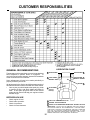
LUBRICATION CHART
GENERAL RECOMMENDATIONS
The warranty on this tractor does not cover items that have
been subjected to operator abuse or negligence. To
receive full value from the warranty, operator must maintain
tractor as instructed in this manual.
Some adjustments will need to be made periodically to
properly maintain your tractor.
All adjustments in the Service and Adjustments section of
this manual should be checked at least once each season.
• Once a year you should replace the spark plug, clean
or replace air filter, and check blades and belts for
wear. A new spark plug and clean air filter assure
proper air-fuel mixture and help your engine run better
and last longer.
2 SPINDLE ZERK
SPINDLE ZERK 2
2 FRONT WHEEL
BEARING ZERK
FRONT WHEEL 2
BEARING ZERK
ENGINE 3
1 ATTACHMENT
CLUTCH
PIVOT(S)
BEFORE EACH USE
•
•
•
•
Check engine oil level.
Check brake operation.
Check tire pressure.
Check for loose fasteners.
1 SAE 30 OR 10W30 MOTOR OIL API
2 GENERAL PURPOSE GREASE
3 REFER TO CUSTOMER RESPONSIBILITIES “ENGINE” SECTION
IMPORTANT: DO NOT OIL OR GREASE THE PIVOT POINTS
WHICH HAVE SPECIAL NYLON BEARINGS. VISCOUS LUBRICANTS WILL ATTRACT DUST AND DIRT THAT WILL SHORTEN
THE LIFE OF THE SELF-LUBRICATING BEARINGS. IF YOU
FEEL THEY MUST BE LUBRICATED, USE ONLY A DRY, POWDERED GRAPHITE TYPE LUBRICANT SPARINGLY.
15
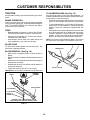
CUSTOMER RESPONSIBILITIES
TRACTOR
TO SHARPEN BLADE (See Fig. 15)
Always observe safety rules when performing any maintenance.
Care should be taken to keep the blade balanced. An
unbalanced blade will cause excessive vibration and eventual damage to mower and engine.
• The blade can be sharpened with a file or on a grinding
wheel. Do not attempt to sharpen while on the mower.
• To check blade balance, you will need a 5/8" diameter
steel bolt, pin, or a cone balancer. (When using a cone
balancer, follow the instructions supplied with balancer).
• Slide blade on to an unthreaded portion of the steel bolt
or pin and hold the bolt or pin parallel with the ground.
If blade is balanced, it should remain in a horizontal
position. If either end of the blade moves downward,
sharpen the heavy end until the blade is balanced.
NOTE: Do not use a nail for balancing blade. The lobes of
the center hole may appear to be centered, but are not.
BRAKE OPERATION
If tractor requires more than six (6) feet stopping distance
at high speed in highest gear, then brake must be adjusted.
(See "TO ADJUST BRAKE" in the Service and Adjustments section of this manual).
TIRES
•
•
•
Maintain proper air pressure in all tires (See "PRODUCT SPECIFICATIONS" on page 3 of this manual).
Keep tires free of gasoline, oil, or insect control chemicals which can harm rubber.
Avoid stumps, stones, deep ruts, sharp objects and
other hazards that may cause tire damage.
BLADE CARE
For best results mower blades must be kept sharp. Replace bent or damaged blades.
CENTER HOLE
BLADE REMOVAL (See Fig. 14)
•
•
•
•
•
Raise mower to highest position to allow access to
blades.
Remove hex bolt, lock washer and flat washer securing
blade.
Install new or resharpened blade with trailing edge up
towards deck as shown.
Reassemble hex bolt, lock washer and flat washer in
exact order as shown.
Tighten bolt securely (30-35 Ft. Lbs. torque).
BLADE
5/8" BOLT OR PIN
IMPORTANT: BLADE BOLT IS GRADE 8 HEAT TREATED.
FIG. 15
MANDREL
ASSEMBLY
BLADE
TRAILING EDGE
FLAT WASHER
LOCK WASHER
HEX BOLT
(GRADE 8)*
*A GRADE 8 HEAT TREATED BOLT CAN BE
IDENTIFIED BY SIX LINES ON THE BOLT HEAD.
FIG. 14
16
CUSTOMER RESPONSIBILITIES
BATTERY (See Fig. 16)
TRANSAXLE COOLING
Your tractor has a battery charging system which is sufficient for normal use. However, periodic charging of the
battery with an automotive charger will extend it's life.
• Acid solution level in each battery cell should be even
with bottoms of vent wells. Add only distilled or iron free
water if necessary. Do not overfill.
• Keep battery and terminals clean.
• Keep battery bolts tight.
• Keep vent caps tight and small vent holes in caps open.
• Recharge at 6 amperes for 1 hour.
TO CLEAN BATTERY AND TERMINALS Corrosion and dirt on the battery and terminals can cause
the battery to "leak" power.
• Open battery box door.
• Disconnect BLACK battery cable first then RED battery cable and remove battery from tractor.
• Wash battery with solution of four tablespoons of
baking soda to one gallon of water. Be careful not to get
the soda solution into the cells.
• Rinse the battery with plain water and dry.
• Clean terminals and battery cable ends with wire brush
until bright.
• Coat terminals with grease or petroleum jelly.
• Reinstall battery (See "INSTALL BATTERY" in the
Assembly section of this manual).
The fan and cooling fins of transmission should be kept
clean to assure proper cooling.
Do not attempt to clean fan or transmission while engine is
running or while the transmission is hot.
• Inspect cooling fan to be sure fan blades are intact and
clean.
• Inspect cooling fins for dirt, grass clippings and other
materials. To prevent damage to seals, do not use
compressed air or high pressure sprayer to clean
cooling fins.
CUT AWAY VIEW
TRANSAXLE PUMP FLUID
The transaxle was sealed at the factory and fluid maintenance is not required for the life of the transaxle. Should the
transaxle ever leak or require servicing, contact your nearest authorized service center/department.
VENT CAP
VENT
WELL
BATTERY
CELL ACID
LEVEL
FIG. 16
V-BELTS
Check V-belts for deterioration and wear after 100 hours
and replace if necessary. The belts are not adjustable.
Replace belts if they begin to slip from wear.
17
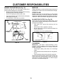
CUSTOMER RESPONSIBILITIES
CLEAN AIR SCREEN (See Fig. 19)
ENGINE
Air screen must be kept free of dirt and chaff to prevent
engine damage from overheating. Clean with a wire brush
or compressed air to remove dirt and stubborn dried gum
fibers.
LUBRICATION
Only use high quality detergent oil rated with API service
classification SF or SG. Select the oil's SAE viscosity grade
according to your expected operating temperature.
COVER
KNOB
CARTRIDGE
NUT
COVER
NOTE: Although multi-viscosity oils (5W30, 10W30 etc.)
improve starting in cold weather, these multi-viscosity oils
will result in increased oil consumption when used above
32°F. Check your engine oil level more frequently to avoid
possible engine damage from running low on oil.
Change the oil after the first two hours of operation and
every 25 hours thereafter or at least once a year if the
tractor is not used for 25 hours in one year.
Check the crankcase oil level before starting the engine
and after each eight (8) hours of continuous use. Tighten
oil fill cap/dipstick securely each time you check the oil
level.
PAPER
CARTRIDGE
FOAM
PRE-CLEANER
BASE
FIG. 18
AIR FILTER (See Fig. 18)
Your engine will not run properly using a dirty air filter.
Clean the foam pre-cleaner after every 25 hours of operation or every season. Service paper cartridge every 100
hours of operation or every season, whichever occurs first.
Service air cleaner more often under dusty conditions.
• Remove knob(s) and cover.
TO SERVICE PRE-CLEANER
• Slide foam pre-cleaner off cartridge.
• Wash it in liquid detergent and water.
• Squeeze it dry in a clean cloth.
• Saturate it in engine oil. Wrap it in clean, absorbent
cloth and squeeze to remove excess oil.
• If very dirty or damaged, replace pre-cleaner.
• Reinstall pre-cleaner over cartridge.
• Reinstall cover and secure with knob(s).
TO SERVICE CARTRIDGE
• Remove cartridge nut.
• Carefully remove cartridge to prevent debris from entering carburetor. Clean base carefully to prevent
debris from entering carburetor.
• Clean cartridge by tapping gently on flat surface. If very
dirty or damaged, replace cartridge.
• Reinstall cartridge, nut, precleaner, cover and secure
with knob(s).
TO CHANGE ENGINE OIL (See Fig.17)
Determine temperature range expected before oil change.
All oil must meet API service classification SF or SG.
• Be sure tractor is on level surface.
• Oil will drain more freely when warm.
• Catch oil in a suitable container.
• Remove oil fill cap/dipstick. Be careful not to allow dirt
to enter the engine when changing oil.
• Remove drain plug.
• After oil has drained completely, replace oil drain plug
and tighten securely.
• Refill engine with oil through oil fill dipstick tube. Pour
slowly. Do not overfill. For approximate capacity see
“PRODUCT SPECIFICATIONS” on page 3 of this
manual.
• Use gauge on oil fill cap/dipstick for checking level. Be
sure dipstick cap is tightened securely for accurate
reading. Keep oil at “FULL” line on dipstick.
OIL FILL
CAP/DIPSTICK
IMPORTANT: PETROLEUM SOLVENTS, SUCH AS
KEROSENE, ARE NOT TO BE USED TO CLEAN THE
CARTRIDGE. THEY MAY CAUSE DETERIORATION OF
THE CARTRIDGE. DO NOT OIL CARTRIDGE. DO NOT
USE PRESSURIZED AIR TO CLEAN OR DRY
CARTRIDGE.
OIL DRAIN PLUG
FIG. 17
18
CUSTOMER RESPONSIBILITIES
ENGINE COOLING FINS (See Fig. 19)
MUFFLER
Remove any dust, dirt or oil from engine cooling fins to
prevent engine damage from overheating.
• Remove screws from blower housing and lift housing
and dipstick tube assembly off engine.
• Cover oil fill opening to prevent entry of dirt.
• Use compressed air or stiff bristle brush to thoroughly
clean engine cooling fins.
• To reassemble, reverse above procedure.
Inspect and replace corroded muffler and spark arrester (if
equipped) as it could create a fire hazard and/or damage.
SCREWS
SPARK PLUGS
Replace spark plugs at the beginning of each mowing
season or after every 100 hours of operation, whichever
comes first. Spark plug type and gap setting are shown in
"PRODUCT SPECIFICATIONS" on page 3 of this manual.
IN-LINE FUEL FILTER (See Fig. 20)
The fuel filter should be replaced once each season. If fuel
filter becomes clogged, obstructing fuel flow to carburetor,
replacement is required.
• With engine cool, remove filter and plug fuel line
sections.
• Place new fuel filter in position in fuel line.
• Be sure there are no fuel line leaks and clamps are
properly positioned.
• Immediately wipe up any spilled gasoline.
BLOWER HOUSING
SCREWS
AIR SCREEN
DIPSTICK TUBE
ASSEMBLY
CLAMP
ENGINE COOLING FINS
SPARK
PLUG
CLAMP
FUEL FILTER
FIG. 19
CLEANING
FIG. 20
IMPORTANT: F O R B E S T P E R F O R M A N C E , K E E P
MOWER HOUSING FREE OF BUILD-UP, GRASS AND
TRASH. CLEAN UNDERSIDE OF MOWER HOUSING
AFTER EACH USE.
•
Clean engine, battery, seat, finish, etc. of all foreign
matter.
• Keep finished surfaces and wheels free of all gasoline,
oil, etc.
• Protect painted surfaces with automotive type wax.
We do not recommend using a garden hose to clean your
tractor unless the electrical system, muffler, air filter and
carburetor are covered to keep water out. Water in engine
can result in a shortened engine life.
19
SERVICE AND ADJUSTMENTS
CAUTION: BEFORE PERFORMING ANY SERVICE OR ADJUSTMENTS:
•
Depress clutch/brake pedal fully and set parking brake.
•
Place motion control lever in neutral (N) position.
•
Place attachment clutch in "DISENGAGED" position.
•
Turn ignition key "OFF" and remove key.
•
Make sure the blades and all moving parts have completely stopped.
•
Disconnect spark plug wire from spark plug and place wire where it cannot come in
contact with plug.
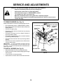
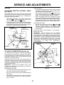
TO REMOVE MOWER (See Fig. 21)
Mower will be easier to remove from the right side of tractor.
• Place attachment clutch in “DISENGAGED” position.
• Move attachment lift lever forward to lower mower to its
lowest position.
• Roll belt off engine pulley.
• Disconnect clutch rod from clutch lever by removing
retainer spring.
• Disconnect anti-sway bar from chassis bracket by
removing retainer spring.
• Disconnect suspension arms from rear deck brackets
by removing retainer springs.
• Disconnect front links from deck by removing retainer
springs.
• Raise lift lever to raise suspension arms. Slide mower
out from under tractor.
CLUTCH LEVER
CLUTCH ROD
SUSPENSION
ARMS
RETAINER
SPRING
TO INSTALL MOWER (See Fig. 21)
•
•
ENGINE
PULLEY
RETAINER
SPRINGS
(BOTH SIDES)
IMPORTANT:
IF AN ATTACHMENT OTHER THAN THE
MOWER IS TO BE MOUNTED TO THE TRACTOR, THE
R.H. AND L.H. SUSPENSION ARMS MUST BE REMOVED
FROM TRACTOR.
•
•
RETAINER
SPRING
ANTI-SWAY BAR
Raise attachment lift lever to its highest position.
Slide mower under tractor with discharge guard to right
side of tractor.
Lower lift lever to its lowest position.
Install mower in reverse order of removal instructions.
RETAINER
SPRINGS
(BOTH SIDES)
FIG. 21
20
SERVICE AND ADJUSTMENTS
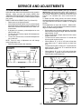
FRONT-TO-BACK ADJUSTMENT (See Figs. 24 and 25)
TO LEVEL MOWER HOUSING
IMPORTANT: DECK MUST BE LEVEL SIDE-TO-SIDE. IF
THE FOLLOWING FRONT-TO-BACK ADJUSTMENT IS
NECESSARY, BE SURE TO ADJUST BOTH FRONT LINKS
EQUALLY SO MOWER WILL STAY LEVEL SIDE-TOSIDE.
Adjust the mower while tractor is parked on level ground or
driveway. Make sure tires are properly inflated (See
“PRODUCT SPECIFICATIONS” on page 3 of this manual).
If tires are over or underinflated, you will not properly adjust
your mower.
To obtain the best cutting results, the mower housing
should be adjusted so that the front is approximately 1/4" to
3/4" lower than the rear when the mower is in its highest
position.
Check adjustment on right side of tractor. Measure distance “D” directly in front and behind the mandrel at bottom
edge of mower housing as shown.
• Before making any necessary adjustments, check that
both front links are equal in length. Both links should be
approximately 10-3/8".
• If links are not equal in length, adjust one link to same
length as other link.
• To lower front of mower loosen nut “E” on both front
links an equal number of turns.
• When distance “D” is 1/4" to 3/4" lower at front than
rear, tighten nuts “F” against trunnion on both front
links.
• To raise front of mower, loosen nut “F” from trunnion on
both front links. Tighten nut “E” on both front links an
equal number of turns.
• When distance “D” is 1/4" to 3/4" lower at front than
rear, tighten nut “F” against trunnion on both front links.
• Recheck side-to-side adjustment.
SIDE-TO-SIDE ADJUSTMENT (See Figs. 22 and 23)
• Raise mower to its highest position.
• At the midpoint of both sides of mower, measure height
from bottom edge of mower to ground. Distance “A” on
both sides of mower should be the same or within 1/4"
of each other.
• If adjustment is necessary, make adjustment on one
side of mower only.
• To raise one side of mower, tighten lift link adjustment
nut on that side.
• To lower one side of mower, loosen lift link adjustment
nut on that side.
NOTE: Three full turns of adjustment nut will change
mower height about 1/8".
• Recheck measurements after adjusting.
BOTTOM EDGE
OF MOWER TO
GROUND
BOTTOM EDGE
OF MOWER TO
GROUND
MANDREL
A
GROUND LINE
“D”
FIG. 22
“D”
FIG. 24
BOTH FRONT LINKS MUST BE EQUAL IN LENGTH
SUSPENSION ARM
NUT “E”
LIFT LINK ADJUSTMENT NUT
NUT “F”
FIG. 23
FRONT LINKS
21
TRUNNION
FIG. 25
SERVICE AND ADJUSTMENTS
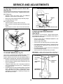
TO REPLACE MOWER BLADE DRIVE BELT
(See Fig. 26)
WITH PARKING BRAKE "ENGAGED"
The mower blade drive belt may be replaced without tools.
Park the tractor on level surface. Engage parking brake.
NUT “A”
BELT REMOVAL • Remove mower from tractor (See “TO REMOVE
MOWER” in this section of this manual).
• Work belt off both mandrel pulleys and idler pulleys.
• Pull belt away from mower.
JAM NUT
BELT INSTALLATION • Install new belt in reverse order of removal.
• Make sure belt is in all pulley grooves and inside all belt
guides.
• Install mower in reverse order of removal instructions.
MANDREL
PULLEY
OPERATING ARM
FIG. 27
IDLER
PULLEYS
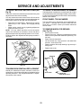
TO REPLACE MOTION DRIVE BELT
(See Fig.28)
Park the tractor on level surface. Engage parking brake.
For assistance, there is a belt installation guide decal on
bottom side of left footrest.
• Remove mower (See “TO REMOVE MOWER” in this
section of this manual.)
• Remove upper belt keeper.
• Remove belt from stationary idler and clutching idler.
• Pull belt slack toward rear of tractor. Carefully remove
belt upwards from transmission input pulley and over
cooling fan blades.
• Pull belt toward front of tractor and remove downward
from around engine pulley.
• Install new belt by reversing above procedure.
MANDREL
PULLEY
FIG. 26
IMPORTANT: MAKE SURE UPPER BELT KEEPER IS
POSITIONED PROPERLY BETWEEN LOCATOR TABS.
TO ADJUST BRAKE (See Fig. 27)
Your tractor is equipped with an adjustable brake system
which is mounted on the right side of the transaxle.
If tractor requires more than six (6) feet stopping distance
at high speed in highest gear, then brake must be adjusted.
• Depress clutch/brake pedal and engage parking brake.
• Measure distance between brake operating arm and
nut "A" on brake rod.
• If distance is other than 1-3/4", loosen jam nut and turn
nut "A" until distance becomes 1-3/4". Retighten jam
nut against nut "A".
• Road test tractor for proper stopping distance as stated
above. Readjust if necessary. If stopping distance is
still greater than six (6) feet in highest gear, further
maintenance is necessary. Contact your nearest authorized service center.
ENGINE
PULLEY
LOCATOR
TABS
CLUTCHING
IDLER
UPPER BELT
KEEPER
STATIONARY
IDLER
TRANSMISSION
INPUT PULLEY
FIG. 28
22
SERVICE AND ADJUSTMENTS
TO ADJUST MOTION CONTROL LEVER (See
Fig.29)
TO ADJUST STEERING WHEEL ALIGNMENT
If steering wheel crossbars are not horizontal (left to right)
when wheels are positioned straight forward, remove steering wheel and reassemble per instructions in the Assembly
section of this manual.
The motion control lever has been preset at the factory and
adjustment should not be necessary.
If for any reason the motion control lever will not hold its
position while at a selected speed, it may be adjusted at the
friction pack located on the right side of transmission.
• Park tractor on level surface. Stop tractor by turning
ignition key to “OFF” position, and engage parking
brake.
• Adjust motion control lever by tightening adjustment
locknut one half (1/2) turn.
NOTE: If for any reason the effort to move the motion
control lever becomes too excessive, reverse the above
adjustment procedure by loosening locknut 1/4 to 1/2 turn.
Road test tractor after adjustment and repeat procedure if
necessary.
FRONT WHEEL TOE-IN/CAMBER
The front wheel toe-in and camber are not adjustable on
your tractor. If damage has occurred to affect the front
wheel toe-in or camber, contact your nearest authorized
service center.
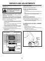
TO REMOVE WHEEL FOR REPAIRS
(See Fig. 30)
•
•
•
•
•
•
Block up axle securely.
Remove axle cover, retaining ring and washers to allow
wheel removal (rear wheel contains a square key - Do
not lose).
Repair tire and reassemble.
On rear wheels only: align grooves in rear wheel hub
and axle. Insert square key.
Replace washers and snap retaining ring securely in
axle groove.
Replace axle cover.
WASHERS
RETAINING
RING
ADJUSTMENT
LOCKNUT
FIG. 29
TRANSMISSION REMOVAL/REPLACEMENT
Should your transmission require removal for service or
replacement, it should be purged after reinstallation before
operating the tractor. See “Purge transmission” in Operation section of this manual.
AXLE COVER
SQUARE KEY
(REAR WHEEL ONLY)
FIG. 30
23
SERVICE AND ADJUSTMENTS
TO REPLACE FUSE
TO START ENGINE WITH A WEAK BATTERY
(See Fig. 31)
Replace with 30 amp automotive-type plug-in fuse. The
fuse holder is located behind the dash.
CAUTION: Lead-acid batteries generate explosive gases. Keep sparks, flame
and smoking materials away from batteries. Always wear eye protection
when around batteries.
TO REPLACE HEADLIGHT BULB
•
•
•
If your battery is too weak to start the engine, it should be
recharged. If "jumper cables" are used for emergency
starting, follow this procedure:
•
IMPORTANT: YOUR TRACTOR IS EQUIPPED WITH A
12 VOLT NEGATIVE GROUNDED SYSTEM. THE OTHER
VEH ICL E M US T A LSO BE A 12 VO LT NE GAT IVE
GROUNDED SYSTEM. DO NOT USE YOUR TRACTOR
BATTERY TO START OTHER VEHICLES.
TO ATTACH JUMPER CABLES -
•
•
•
INTERLOCKS AND RELAYS
Loose or damaged wiring may cause your tractor to run
poorly, stop running or prevent it from starting.
• Check wiring. See the electrical wiring diagram in the
Repair Parts section of this manual.
Connect each end of the RED cable to the POSITIVE
(+) terminal of each battery, taking care not to short
against chassis.
Connect one end of the BLACK cable to the NEGATIVE (-) terminal of fully charged battery.
Connect the other end of the BLACK cable to a good
CHASSIS GROUND, away from fuel tank and battery.
TO REMOVE HOOD AND GRILL ASSEMBLY
(See Fig.32)
•
•
•
TO REMOVE CABLES, REVERSE ORDER • BLACK cable first from chassis and then from the fully
charged battery.
• RED cable last from both batteries.
POSITIVE TERMINAL
Raise hood.
Pull bulb holder out of the hole in the backside of the
grill.
Replace bulb in holder and push bulb holder securely
back into the hole in the backside of the grill.
Close hood.
•
Raise hood.
Unsnap headlight wire connector.
Stand in front of tractor. Grasp hood at sides, tilt toward
engine and lift off of tractor.
To replace, reverse above procedure.
NEGATIVE TERMINAL
HOOD
HEADLIGHT
WIRE
CONNECTOR
CHASSIS
CABLES
FIG. 32
CHARGED
BATTERY
POSITIVE TERMINAL
NEGATIVE TERMINAL
FIG. 31
24
SERVICE AND ADJUSTMENTS
ENGINE
FINAL SETTING • Start engine and allow to warm for five minutes. Make
final adjustments with engine running and shift/motion
control lever in neutral (N) position.
• Move throttle control lever to slow (
) position. With
finger, rotate and hold throttle lever against idle speed
screw. Turn idle speed screw to attain 1750 RPM.
• While still holding throttle lever against idle speed
screw, turn idle mixture valve in (clockwise) until engine begins to die and then turn out (counterclockwise)
until engine runs rough. Turn valve to a point midway
between those two positions. Release throttle lever.
TO ADJUST THROTTLE CONTROL CABLE
(See Fig.33)
The throttle control has been preset at the factory and
adjustment should not be necessary. Check adjustment as
described below before loosening cable. If adjustment is
necessary, proceed as follows:
• With engine not running, move throttle control lever
from slow (
) to choke ( ) position. Slowly move
lever from choke ( ) to fast ( ) position.
• Check that holes “A” in governor control lever and hole
in governor plate line-up. If holes “A” are not aligned,
loosen clamp screw and move throttle cable until holes
are aligned. Tighten clamp screw securely.
GOVERNOR
CONTROL LEVER
ACCELERATION TEST • Move throttle control lever from slow (
) to fast ( )
position. If engine hesitates or dies, turn idle mixture
valve out (counterclockwise) 1/8 turn. Repeat test and
continue to adjust, if necessary, until engine accelerates smoothly.
High speed stop is factory adjusted. Do not adjust damage may result.
GOVERNOR
CONTROL PLATE
IMPORTANT: NEVER TAMPER WITH THE ENGINE
GOVERNOR, WHICH IS FACTORY SET FOR PROPER
ENGINE SPEED. OVERSPEEDING THE ENGINE ABOVE
THE FACTORY HIGH SPEED SETTING CAN BE
DANGEROUS. IF YOU THINK THE ENGINE-GOVERNED
HIGH SPEED NEEDS ADJUSTING, CONTACT YOUR
NEAREST
AUTHORIZED
SERVICE
CENTER/
DEPARTMENT, WHICH HAS PROPER EQUIPMENT AND
EXPERIENCE
TO
MAKE
ANY
NECESSARY
ADJUSTMENTS.
THROTTLE
LEVER
HOLES “A”
CLAMP
SCREW
IDLE SPEED
SCREW
THROTTLE
CABLE
FIG. 33
TO ADJUST CARBURETOR (See Fig. 34)
The carburetor has been preset at the factory and adjustment should not be necessary. However, minor adjustment may be required to compensate for differences in fuel,
temperature, altitude or load. If the carburetor does need
adjustment, proceed as follows:
In general, turning idle mixture valve in (clockwise) decreases the supply of fuel to the engine giving a leaner fuel/
air mixture. Turning the idle mixture valve out (counterclockwise) increases the supply of fuel to the engine giving
a richer fuel/air mixture.
IMPORTANT: DAMAGE TO THE NEEDLE VALVE AND
THE SEAT IN CARBURETOR MAY RESULT IF SCREW IS
TURNED IN TOO TIGHT.
IDLE MIXTURE
VALVE
FIG. 34
PRELIMINARY SETTING • Air cleaner assembly must be assembled to the carburetor when making carburetor adjustments.
• Be sure the throttle control cable is adjusted properly
(see above).
• With engine off turn idle mixture valve in (clockwise)
closing it finger tight and then turn out (counterclockwise) 1 full turn.
25
STORAGE
Immediately prepare your tractor for storage at the end of
the season or if the tractor will not be used for 30 days or
more.
ENGINE
FUEL SYSTEM
IMPORTANT: IT IS IMPORTANT TO PREVENT GUM
DEPO SITS FRO M FO RMIN G I N ES SENT IAL FUEL
SYSTEM PARTS SUCH AS CARBURETOR, FUEL FILTER,
FUEL HOSE, OR TANK DURING STORAGE. ALSO,
EXPERIENCE INDICATES THAT ALCOHOL BLENDED
FUELS (CALLED GASOHOL OR USING ETHANOL OR
METHANOL) CAN ATTRACT MOISTURE WHICH LEADS
TO SEPARATION AND FORMATION OF ACIDS DURING
STORAGE. ACIDIC GAS CAN DAMAGE THE FUEL
SYSTEM OF AN ENGINE WHILE IN STORAGE.
CAUTION: Never store the tractor with
gasoline in the tank inside a building
where fumes may reach an open flame
or spark. Allow the engine to cool
before storing in any enclosure.
TRACTOR
Remove mower from tractor for winter storage. When
mower is to be stored for a period of time, clean it thoroughly, remove all dirt, grease, leaves, etc. Store in a
clean, dry area.
• Clean entire tractor (See “CLEANING” in the Customer
Responsibilities section of this manual).
• Inspect and replace belts, if necessary (See belt replacement instructions in the Service and Adjustments
section of this manual).
• Lubricate as shown in the Customer Responsibilities
section of this manual.
• Be sure that all nuts, bolts and screws are securely
fastened. Inspect moving parts for damage, breakage
and wear. Replace if necessary.
• Touch up all rusted or chipped paint surfaces; sand
lightly before painting.
•
•
Drain the fuel tank.
Start the engine and let it run until the fuel lines and
carburetor are empty.
• Never use engine or carburetor cleaner products in the
fuel tank or permanent damage may occur.
• Use fresh fuel next season.
NOTE: Fuel stabilizer is an acceptable alternative in
minimizing the formation of fuel gum deposits during storage. Add stabilizer to gasoline in fuel tank or storage
container. Always follow the mix ratio found on stabilizer
container. Run engine at least 10 minutes after adding
stabilizer to allow the stabilizer to reach the carburetor. Do
not drain the gas tank and carburetor if using fuel stabilizer.
ENGINE OIL
BATTERY
Drain oil (with engine warm) and replace with clean engine
oil. (See “ENGINE” in the Customer Responsibilities
section of this manual).
•
•
CYLINDERS
•
•
•
•
Fully charge the battery for storage.
After a period of time in storage, battery may require
recharging.
To help prevent corrosion and power leakage during
long periods of storage, battery cables should be
disconnected and battery cleaned thoroughly (see “TO
CLEAN BATTERY AND TERMINALS” in the Customer Responsibilities section of this manual).
After cleaning, leave cables disconnected and place
cables where they cannot come in contact with battery
terminals.
Be sure battery drain tube is securely attached.
If battery is removed from tractor for storage, do not
store battery directly on concrete or damp surfaces.
•
•
•
•
Remove spark plug(s).
Pour one ounce of oil through spark plug hole(s) into
cylinder(s).
Turn ignition key to “START” position for a few seconds
to distribute oil.
Replace with new spark plug(s).
OTHER
•
•
•
•
Do not store gasoline from one season to another.
Replace your gasoline can if your can starts to rust.
Rust and/or dirt in your gasoline will cause problems.
If possible, store your tractor indoors and cover it to
give protection from dust and dirt.
Cover your tractor with a suitable protective cover that
does not retain moisture. Do not use plastic. Plastic
cannot breathe which allows condensation to form and
will cause your tractor to rust.
IMPORTANT: NEVER COVER TRACTOR WHILE ENGINE
AND EXHAUST AREAS ARE STILL WARM.
26
TROUBLESHOOTING POINTS
PROBLEM
CAUSE
CORRECTION
Will not start
1.
2.
3.
4.
5.
6.
7.
Out of fuel.
Engine not “CHOKED” properly.
Engine flooded.
Bad spark plug.
Dirty air filter.
Dirty fuel filter.
Water in fuel.
1.
2.
3.
4.
5.
6.
7.
8.
9.
10.
Loose or damaged wiring.
Carburetor out of adjustment.
Engine valves out of adjustment.
8.
9.
10.
Fill fuel tank.
See “TO START ENGINE” in Operation section.
Wait several minutes before attempting to start.
Replace spark plug.
Clean/replace air filter.
Replace fuel filter.
Drain fuel tank and carburetor, refill tank with fresh
gasoline and replace fuel filter.
Check all wiring.
Contact an authorized service center/department.
Contact an authorized service center/department.
Hard to start
1.
2.
3.
4.
5.
6.
7.
8.
Dirty air filter.
Bad spark plug.
Weak or dead battery.
Dirty fuel filter.
Stale or dirty fuel.
Loose or damaged wiring.
Carburetor out of adjustment.
Engine valves out of adjustment.
1.
2.
3.
4.
5.
6.
7.
8.
Clean/replace air filter.
Replace spark plug.
Recharge or replace battery.
Replace fuel filter.
Drain fuel tank and refill with fresh gasoline.
Check all wiring.
Contact an authorized service center/department.
Contact an authorized service center/department.
Engine will not turn over
1.
2.
3.
4.
5.
6.
7.
8.
9.
Clutch/brake pedal not depressed.
Attachment clutch is engaged.
Weak or dead battery.
Blown fuse.
Corroded battery terminals.
Loose or damaged wiring.
Faulty ignition switch.
Faulty solenoid or starter.
Faulty operator presence switch(es).
1.
2.
3.
4.
5.
6.
7.
8.
9.
Depress clutch/brake pedal.
Disengage attachment clutch.
Recharge or replace battery.
Replace fuse.
Clean battery terminals.
Check all wiring.
Check/replace ignition switch.
Check/replace solenoid or starter.
Contact an authorized service center/department.
Engine clicks but will not
start
1.
2.
3.
4.
Weak or dead battery.
Corroded battery terminals.
Loose or damaged wiring.
Faulty solenoid or starter.
1.
2.
3.
4.
Recharge or replace battery.
Clean battery terminals.
Check all wiring.
Check/replace solenoid or starter.
Loss of power
1.
2.
3.
4.
5.
6.
7.
8.
9.
Cutting too much grass/too fast.
Throttle in “CHOKE” position.
Build-up of grass, leaves and trash under mower.
Dirty air filter.
Low oil level/dirty oil.
Faulty spark plug.
Dirty fuel filter.
Stale or dirty fuel.
Water in fuel.
1.
2.
3.
4.
5.
6.
7.
8.
9.
Set in “Higher Cut” position/reduce speed.
Adjust throttle control.
Clean underside of mower housing.
Clean/replace air filter.
Check oil level/change oil.
Clean and regap or change spark plug.
Replace fuel filter.
Drain fuel tank and refill with fresh gasoline.
Drain fuel tank and carburetor, refill tank with fresh
gasoline and replace fuel filter.
Connect and tighten spark plug wire.
Clean engine air screen/fins.
Clean/replace muffler.
Check all wiring.
Contact an authorized service center/department.
Contact an authorized service center/department.
10.
11.
12.
13.
14.
15.
Excessive vibration
1.
2.
3.
Spark plug wire loose.
Dirty engine air screen/fins.
Dirty/clogged muffler.
Loose or damaged wiring.
Carburetor out of adjustment.
Engine valves out of adjustment.
10.
11.
12.
13.
14.
15.
Worn, bent or loose blade.
Bent blade mandrel.
Loose/damaged part(s).
1.
2.
3.
27
Replace blade. Tighten blade bolt.
Replace blade mandrel.
Tighten loose part(s). Replace damaged parts.
TROUBLESHOOTING POINTS
PROBLEM
CAUSE
CORRECTION
Engine continues to run
when operator leaves seat
with attachment clutch
engaged
1.
Faulty operator-safety presence control system.
1.
Check wiring, switches and connections. If not
corrected, contact an authorized service center/
department.
Poor cut - uneven
1.
2.
3.
4.
5.
Worn, bent or loose blade.
Mower deck not level.
Buildup of grass, leaves, and trash under mower.
Bent blade mandrel.
Clogged mower deck vent holes from buildup of
grass, leaves, and trash around mandrels.
1.
2.
3.
4.
5.
Replace blade. Tighten blade bolt.
Level mower deck.
Clean underside of mower housing.
Replace blade mandrel.
Clean around mandrels to open vent holes.
Mower blades will not
rotate
1.
2.
3.
4.
Obstruction in clutch mechanism.
Worn/damaged mower drive belt.
Frozen idler pulley.
Frozen blade mandrel.
1.
2.
3.
4.
Remove obstruction.
Replace mower drive belt.
Replace idler pulley.
Replace blade mandrel.
Poor grass discharge
1.
2.
3.
4.
5.
6.
7.
8.
9.
10.
11.
Engine speed too slow.
Travel speed too fast.
Wet grass.
Mower deck not level.
Low/uneven tire air pressure.
Worn, bent or loose blade.
Buildup of grass, leaves and trash under mower.
Mower drive belt worn.
Blades improperly installed.
Improper blades used.
Clogged mower deck vent holes from buildup of
grass, leaves, and trash around mandrels.
1.
2.
3.
4.
5.
6.
7.
8.
9.
10.
11.
Place throttle control in “FAST” position.
Shift to slower speed.
Allow grass to dry before mowing.
Level mower deck.
Check tires for proper air pressure.
Replace/sharpen blade. Tighten blade bolt.
Clean underside of mower housing.
Replace mower drive belt.
Reinstall blades sharp edge down.
Replace with blades listed in this manual.
Clean around mandrels to open vent holes.
Headlight(s) not working
(if so equipped)
1.
2.
3.
4.
5.
Switch is “OFF”.
Bulb(s) burned out.
Faulty light switch.
Loose or damaged wiring.
Blown fuse.
1.
2.
3.
4.
5.
Turn switch “ON”.
Replace bulb(s).
Check/replace light switch.
Check wiring and connections.
Replace fuse.
Battery will not charge
1.
2.
3.
4.
Bad battery cell(s).
Poor cable connections.
Faulty regulator (if so equipped).
Faulty alternator.
1.
2.
3.
4.
Replace battery.
Check/clean all connections.
Replace regulator.
Replace alternator.
Loss of drive
1.
2.
3.
Freewheel control in “disengaged” position.
Motion drive belt worn, damaged, or broken.
Air trapped in transmission during shipment
or servicing.
1.
2.
3.
Place freewheel control in “engaged” position.
Replace motion drive belt.
Purge transmission.
Engine “backfires”
when turning engine
“OFF”
1.
Engine throttle control not set at “SLOW”
position for 30 seconds before stopping engine.
1.
Move throttle control to “SLOW” position and allow
to idle for 30 seconds before stopping engine.
28
TRACTOR - MODEL NO. LTH125 (HC125H42C), PRODUCT NO. 954 00 27-21
SCHEMATIC
29
REPAIR PARTS
TRACTOR- -MODEL NO. LTH125 (HC125H42C),
PRODUCT NO. 954 00 27-21
ELECTRICAL
30
REPAIR PARTS
TRACTOR- -MODEL NO. LTH125 (HC125H42C),
PRODUCT NO. 954 00 27-21
ELECTRICAL
KEY
NO.
PART
NO.
1
2
3
4
5
6
7
8
9
19
20
21
22
23
24
25
26
28
29
30
31
32
33
35
36
38
39
40
41
42
43
44
45
46
70
71
532121265
874760412
819091016
810040400
532121264
873220400
532109238
532129965
532109596
810090400
873350400
532136850
532004152
811150400
532124780
532132202
532108824
532124773
532121305
532140301
532124211
532141226
532122147
532108236
817021008
532140336
532109553
532140707
871110408
532131563
532138406
873640400
532140844
532141940
532141163
532140710
DESCRIPTION
Battery 12 Volt 25 Amp
Bolt Hex Hd 1/4-20unc X 3/4
Washer 9/32 X 5/8 X 16 Ga
Washer Lock Hvy Helical 1/4
Caps Battery 20/25/30 AMP
Nut Fin Hex 1/4-20 Unc
Tube Plastic 20"
Battery Case Hng Mech
Clamp Hose Olive
Washer Lock 1/4
Nut Jam Hex 1/4-20 Unc
Harness Asm Light W/4152j
Bulb Light #1156
Washer Lock Internal Tooth 1/4
Cable Battery 6 Ga 11"red
Cable Battery 6 Ga 43"red
Fuse 30 AMP Auto Green
Cable Ground 6 Ga 12"black
Switch Plunger Nc Gray
Switch Ign 4 Pos.
Nut Ignition
Cover Sw Key Blk 1 25 Text SLT
Key Ign
Bracket Switch Clutch
Screw Tap Hex #10-24unc X 1/2
Bracket Switch Interlock
Switch Intlk Clutch Gry 4 Term
Harness Ign Lt Mech Dash
Bolt Fin Hex 1/4-20 x 1/2
Cover Terminal Red
Solenoid
Nut Keps Hex 1/4-20 Unc
Adapter Ammeter rectangular
Protection Wire Loop (Hourmeter)
Harness Eng. B&S
Harness Dash Lt Private Label
NOTE: All component dimensions given in U.S. inches.
1 inch = 25.4 mm
31
REPAIR PARTS
TRACTOR- -MODEL NO. LTH125 (HC125H42C),
PRODUCT NO. 954 00 27-21
CHASSIS AND ENCLOSURES
32
REPAIR PARTS
TRACTOR- -MODEL NO. LTH125 (HC125H42C),
PRODUCT NO. 954 00 27-21
CHASSIS AND ENCLOSURES
KEY
NO.
PART
NO.
-1
2
3
4
5
6
8
9
10
11
12
13
14
17
20
23
24
25
26
28
29
30
31
33
34
35
37
38
39
48
49
50
51
52
53
54
55
57
58
68
532005479
532140341
532140356
817490612
819131216
811050600
532145206
532126471
532140072
872140608
532140311
532145660
532140178
817490608
532144320
532140281
532124028
874780616
819131312
873800600
532140141
532140273
532143050
532136619
532124899
532124914
872110606
817490512
532139886
532139887
532138096
817490412
532142779
873800400
819091416
532140219
817030814
532143007
874780412
532140806
873510400
DESCRIPTION
Plug Button
Chassis Weldment 11ga
Drawbar, Stretch
Screw Thdrol 3/8-16x3/4 Ty-tt
Washer 13/32 x 3/4 x 16 Ga.
Washer Lock Ext. Tooth 3/8
Saddle LT Fender Shift
Clip Insulator .406 Mtg Hole
Dash Private Label
Bolt Carriage 3/8-16 x 1
Panel Pnt Dash Lh
Clip Tinnerman Grille Private Label
Panel Dash Rh Weldment
Screw Thdrol 3/8-16x1/2 Ty-tt
Hood Paint Steel Private Label
Support Battery
Bushing
Bolt Fin Hex 3/8-16unc X1
Washer 13/32 X 13/16 X 12 Ga
Nut Lock 3/8-16 Unc
Grille Private Label
Lens Grille Private Label
Fender Pnt
Bracket Pnt Fender
Footrest Pnt Lh
Footrest Pnt Rh
Bolt Rdhd Sht Sqnk 3/8-16 X3/4
Screw Thdrol 5/16-18 X3/4
Bracket, Asm. Pivot, L.H., Mower Rear
Bracket, Asm. Pivot, R.H., Mower Rear
Rivet Push
Screw Hexwsh. Thdrol 1/4-20 x 3/4
Brace
Nut Lock Hex W/Ins 1/4-20
Washer 9/32 x 7/8 x 16 Ga.
Hinge Pickoff Hood
Screw Lock Spider #8 x 7/8
Bracket, Grill
Screw Hex 1/4-20 x 3/4
Air Duct P/L
Nut Keps Hex 1/4-20 UNC
NOTE: All component dimensions given in U.S. inches.
1 inch = 25.4 mm
33
REPAIR PARTS
TRACTOR- -MODEL NO. LTH125 (HC125H42C),
PRODUCT NO. 954 00 27-21
DRIVE
34
REPAIR PARTS
TRACTOR- -MODEL NO. LTH125 (HC125H42C),
PRODUCT NO. 954 00 27-21
DRIVE
KEY
NO.
PART
NO.
1
2
3
8
10
15
16
18
19
21
22
24
25
26
27
28
29
30
31
32
34
35
36
37
38
39
40
41
42
44
45
46
47
48
49
50
51
52
53
55
56
57
59
532140607
532142431
532144698
532141003
876020416
874780544
873800500
874780616
873800600
532140845
532145627
873350600
532106888
819131316
876020412
532145204
532071673
532130807
532127275
874760512
532122424
532120183
819211616
532124963
532123674
874760644
532124965
532109070
819131312
532105706
532110812
812000039
532127783
532123789
532123205
874760624
873680600
873680500
532105710
532105709
874760620
532141416
532140312
DESCRIPTION
Transaxle Assembly
Spring, Return, Brake
Pulley, Transaxle
Rod Shift Hydro LT
Pin Cotter 1/8 x 1 CAD
Bolt Fin Hex 5/16-18 Unc
Nut Lock Hex W/Ins 5/16-18 Unc P
Bolt Fin Hex 3/8-16 Unc x 1 Gr. 5
Nut Lock Hex W/Wsh 3/8-16 Unc
Knob 1/2-13
Rod, Brake Hydro
Nut
Spring, Brake Rod
Washer
Pin Cotter 1/8 x 3/4 CAD.
Rod, Parking Brake
Cap, Parking Brake
Bracket, Transaxle
Keeper Belt Lh
Bolt Hex Hd 5/16-18 Unc x 3/4
Shaft, Foot Pedal
Bearing, Nylon
Washer
Pin, Roll
Pulley, Idler, Flat
Bolt
Spacer, Split
Keeper, Belt Retainer
Washer 13/32 x 13/16 x 12 Gauge
Bearing, Nylon
Washer, Hardened
Ring, Klip
Pulley, Idler, V-Groove
Bellcrank Assembly
Retainer, Belt
Bolt
Nut Crownlock 3/8-16
Nut Crownlock 5/16-18
Link, Clutch
Spring, Return, Clutch
Bolt Fin Hex 3/8-16 Unc x 1-1/4
V-Belt, Ground Drive
Keeper, Center Span
KEY
NO.
PART
NO.
61
62
63
64
65
66
69
70
71
72
73
74
75
76
77
78
81
82
83
84
86
87
88
89
91
92
93
94
95
96
97
98
100
103
104
105
106
108
109
817490612
532124872
532140186
871170764
810040700
532129921
532142432
532134683
532141417
819132012
532141418
532121199
532121749
812000001
532123583
532121748
532141420
532123782
819171216
532141423
532071208
819212016
812000008
532139988
874780536
874780524
532142564
532140462
532144643
532124788
532144201
873510600
819111216
532050831
532141421
871070516
874780520
817541026
532145098
DESCRIPTION
Screw Thdrol. 3/8-16 x 3/4 Ty. TT
Cover, Pedal
Pulley, Engine
Bolt, Hex
Washer
Keeper Belt Engine
Screw
Keeper Belt Engine
Strap Torque Lh Hydro 500 18"
Washer 13/32 x 1-1/4 x 12 Gauge
Strap Torque Rh Hydro 500 18"
Spacer, Split
Washer 25/32 x 1-1/4 x 16 Gauge
E-Ring
Key, Square
Washer 25/32 x 1-5/8 x 16 Gauge
Shaft Asm. Cross Hydro 500
Spring Torsion T/A
Washer 17/32 x 3/4 x 16 Ga.
Rod, Tie Hydro Sph Ball 500
Bushing Rod Strig. 629/632 ID
Washer 21/32 x 1-1/4 x 16 Ga.
Ring Klip #5304-62
Console, Shift
Bolt Fin Hex 5/16-18 x 2-1/4
Bolt Fin Hex 5/6-18 Unc x 1-1/2
Line Fuel Hydro 4"
Fan, Hydro 7"
Control Asm. Bypass Hydro
Retainer Spring 1" Zinc/Cad
Keeper Belt Rh Hydro 500
Nut Keps Hex 3/8-16 Unc
Washer 11/32 x 3/4 x 16 Ga.
Nut Nylon Insert 1/2-20 Unf.
Arm, Control Pump
Screw Cap Hex 5/16 x 18 x 1
Bolt Fin Hex 5/16-18 Unc x 1-1/4
Screw Hex Wh Hd #10-24 x 1-5/8
Adaptor Fan/Hydro Lt Hyd Alum
NOTE: All component dimensions give in U.S. inches.
1 inch = 25.4 mm.
35
REPAIR PARTS
TRACTOR- -MODEL NO. LTH125 (HC125H42C),
PRODUCT NO. 954 00 27-21
STEERING AND FRONT AXLE
36
REPAIR PARTS
TRACTOR- -MODEL NO. LTH125 (HC125H42C),
PRODUCT NO. 954 00 27-21
STEERING AND FRONT AXLE
KEY
NO.
PART
NO.
1
2
3
4
5
6
7
8
9
10
11
12
13
14
15
16
17
18
19
20
21
22
23
24
25
532121472
532142033
532135227
532135228
532124931
532121748
819272016
812000029
532124937
532130468
810040600
873610600
532110438
874011056
873901000
532132624
532140176
532057079
532124035
532126684
810040400
871070410
532127501
532109816
532124036
DESCRIPTION
Wheel Steering Auto Black
Axle Asm Fr LT W/gzks 38/42
Spindle Asm LH
Spindle Asm RH
Bearing Race Thrust Harden
Washer 25/32 X 1-5/8 X 16ga
Washer 27/32 X 1-1/4 X 16 Ga
Ring Klip #t5304-75
Bearing Col Strg Blk
Link Drag Sol Ball Jt 20 064
Washer Lock Hvy Hlcl Spr 3/8
Nut Fin Hex 3/8-24 Unf
Spacer Bearing Axle Front
Bolt Hex 5/8-11 Unc X 3-1/2
Nut Lock Flange 5/8-11 Unc
Pin Axle 5/8 X 1 55/1 54 Lg
Shaft Asm Strg Private Label
Washer Thrust 515x 750x 033
Support Shaft
Washer Shim 1/4 X 5/8 X 062
Washer Lock Hvy Helical 1/4
Screw Hex Socket 1/4-20 X 5/8
Shaft Asm Pittman
Nyliner Snap In
Bracket Steering
KEY
NO.
PART
NO.
26
27
28
29
30
32
36
37
38
39
40
41
42
43
44
45
46
47
50
51
54
55
57
532126847
532136874
819131416
817490612
876020412
532130465
532102803
817431008
532126805
819133808
532124701
532104820
532140216
532121749
532140171
812000029
532121232
532124836
817490412
873800500
874780520
532140285
532140172
DESCRIPTION
Bushing Link Drag Blk LR
Gear Sector 22 Teeth
Washer 13/32 X 7/8 X 16ga
Screw Thdrol 3/8-16x3/4 Ty-tt
Pin Cotter 1/8 X 3/4 Cad
Rod Tie Wire Form 19 75 Mech
Bushing Strg
Screw Slftp #10-16 X 1/2 Ty-b
Insert Cap Strg Wh Au Gen Blk
Washer 13/32 X 2-3/8 X 8 Ga
Nut Lock Center 3/8-24unf
Adaptor Wheel Strg 640/ 635id
Boot Shaft Steering
Washer 25/32 X 1 1/4 X 16 Ga
Shaft Extension Steering
Ring Klip #t5304-75
Cap Spindle Fr Top Blk
Fitting Grease
Screw Hex Wsh Thdrol 1/4-20 x 3/4
Nut Lock Hex w/Insert 5/16-18
Bolt Fin Hex 5/16-18 unc x 1-1/4
Clip Tinnerman
Support Shaft Steering
NOTE: All component dimensions given in U.S. inches.
1 inch = 25.4 mm
37
REPAIR PARTS
TRACTOR- -MODEL NO. LTH125 (HC125H42C),
PRODUCT NO. 954 00 27-21
ENGINE
38
REPAIR PARTS
TRACTOR- -MODEL NO. LTH125 (HC125H42C),
PRODUCT NO. 954 00 27-21
ENGINE
KEY
PART
NO.
NO.
1 532140310
2 817720410
3
------4
13
14
15
16
18
19
20
21
22
23
24
29
532137348
532125593
813280324
813200300
811050600
532136718
532105839
532105838
819091016
532123650
532128953
817021008
532137180
KEY
NO.
DESCRIPTION
Control Th/ch RH Blk Tee Eec
Screw Hex Thd Cut 1/4-20x5/8 T
Engine B&S 12.5HP Icq Dual 1vt
Model No 286707
Muffler LT B&s 12/12.5 HP
Gasket Eng 1 313 Id Tin Plated
Nipple Pipe 3/8 Npt X 3”
Elbow Std 90 Degree 3/8-18 Npt
Washer Lock Ext Tooth 3/8
Shield Heat LT
Receptacle 1/4 Turn dacrotized
Retainer 1/4 Turn 365 OD x .222 ID
Washer 9/32 x 5/8 x 16 Ga
Stud 1/4 Turn (replaces 105751)
Shield Heat Browning LT/YT
Screw Tap Hex #10-24unc X 1/2
Kit Spark Arrestor 1 25
PART
NO.
30
31
32
33
37
38
532127057
532140280
532140527
532123487
532137040
-------
40
44
46
62
72
78
81
532124028
817490412
819091416
810040500
871070512
817490620
873510400
DESCRIPTION
Pinch Weld Hood Black 2.00
Tank Fuel Front 2.00
Cap Asm Fuel W/sym Vented
Clamp Hose Blk
Line Fuel 9 20”
Plug Oil Drain (Order From Engine
Manufacturer)
Bushing Snap Nyl Blk Fuel Line
Screw Hexwsh Thdrol 1/4-20x3/4
Washer 9/32 X 7/8 X 16ga
Washer Lock Hvy Hlcl Spr 5/16
Screw Hexhd Cap 5/16-18x3/4
Screw Thdrol 3/8-16x1-1/4 TYTT
Nut Keps Hex 1/4-20 UNC
NOTE: All component dimensions given in U.S. inches. 1
inch = 25,4 mm.
39
REPAIR PARTS
TRACTOR- -MODEL NO. LTH125 (HC125H42C),
PRODUCT NO. 954 00 27-21
SEAT
KEY
NO.
1
2
3
4
5
6
7
8
9
10
11
12
13
PART
NO.
532127427
532140551
874760616
819131610
532145006
873800600
532124181
817490616
819131614
532140552
532120068
532121246
532121248
DESCRIPTION
Seat V350 Blk/blk Std
Bracket Pivot Seat 8 720
Bolt Fin Hex 3/8-16unc X 1
Washer 13/32 X 3/4 X 10 Ga
Clip Push-In Hinged
Nut Lock Hex w/Ins 3/8-16 Unc
Spring Seat Cprsn 2 250 Blk Zi
Screw Thdrol 3/8-16 X 1 Ty-tt
Washer 13/32 X 1 X 14 Ga
Pan Seat
Knob Seat 1/2-13unc Blk
Bracket Mounting Switch
Bushing Snap Blk Nyl 50 Id
KEY
NO.
14
15
16
17
18
21
PART
NO.
872050411
532134300
532121250
532123976
532124238
532139888
22
24
25
873800500
819171912
532127018
DESCRIPTION
Bolt Rdhd Sht Nk 1/4-20x1-3/8
Spacer Split 28x 96 Yel Zinc
Spring Cprsn 1 27 Blk Pnt
Nut Lock 1/4 Lge Flg Gr 5 Zinc
Cap Spring Seat Blk 1.75 x 1.0
Bolt Shoulder 5/16-18 Type
T.T.T.R.
Nut Lock 5/16-18
Washer 17/32 X 1-3/16 X 12 Ga
Bolt Shoulder 5/16-18 X 62
NOTE: All component dimensions given in U.S. inches.
1 inch = 25.4 mm
40
REPAIR PARTS
TRACTOR- -MODEL NO. LTH125 (HC125H42C),
PRODUCT NO. 954 00 27-21
DECALS
2
15
1
3
8
17
13
4
9
7
10
5
6
KEY
NO.
PART
NO.
1
2
3
4
5
6
7
8
532143609
532143608
532143742
532131582
532129057
532136832
532137259
532140820
9
10
12
13
532142337
532133671
532101892
532121549
12
DESCRIPTION
10
KEY
NO.
Decal Hood Husqvarna LH
Decal Hood Husqvarna RH
Decal Panel Side LH
Decal Fender
Decal Engine 12.5 HP B&S ICQ
Decal, V-Belt Sch 38"/42" LT
Decal Warning MULT-LANGUAGE
Decal Dash Instructions Operating
Eng/Fr
Decal Sdl Cold Start Hydo Eng/Fr
Pad Footrest Ribbed
Decal Clutch/brake Eng/Fr/Ger/Du
Decal Caution Battery Fr/Ger
15
17
-
PART
NO.
532143741
532133795
532138311
532142341
532145999
532146000
DESCRIPTION
Decal Panel Side RH Hydr.
Decal Caution Fender Eng/Fr
Decal Handle Lift Height Adjust
Decal Drawbar Control
Manual Owner's (English)
Manual Owner's (French)
Available accessories (not included with tractor)
- LA018
Tire Chains (18 x 9.5 x 8)
- LSB42
42” Snow Thrower
- LBD48
48” Snow Blade
- LC05
33 lb. Wheel Wts. (pair)
- MP42
Mulching Plate for 42”
WHEELS AND TIRES
41
KEY
NO.
PART
NO.
1
2
3
4
5
6
7
8
9
10
11
532059192
532065139
532106222
532059904
532141446
532124957
532124959
532141447
532106268
532124926
532104757
DESCRIPTION
Cap Valve Tire
Stem Valve
Tire F Ts 15 X 6 0 - 6 Service
Tube Front (Service Item Only)
Rim Asm 6” front Service
Fitting Grease (Front Wheel Only)
Bearing Flange (Service Item Only)
Rim Asm 8” rear Service
Tire R Ts 18x9 5-8 C Service
Tube Rear (Service Item Only)
Cap Axle Blk 1 50 X 1 00
REPAIR PARTS
TRACTOR- -MODEL NO. LTH125 (HC125H42C),
PRODUCT NO. 954 00 27-21
LIFT
42
REPAIR PARTS
TRACTOR- -MODEL NO. LTH125 (HC125H42C),
PRODUCT NO. 954 00 27-21
LIFT
KEY
NO.
PART
NO.
1
2
3
4
5
6
7
8
10
11
12
13
15
16
17
18
19
20
21
22
23
24
25
26
27
28
29
30
31
32
33
34
532136973
532140278
532138284
812000002
819211621
532120183
532109413
532124526
532122512
532139865
532139866
532124670
532127218
873350800
532130171
873800800
532139868
532124660
819151216
812000037
532110807
819131016
532124874
876020308
532126971
873350600
532138057
532110810
532140302
873540600
532140168
817490608
DESCRIPTION
Wire Asm Inner w/plunger
Shaft Asm Lift LH Inf Hgt P/L
Pin Groove
E Ring #5133-62
Washer PLTD 21/32 X 1 X 21ga
Bearing Nylon Blk 629 Id
Grip Handle Bicycle Matte Blk
Button Plunger Black
Spring Cprsn 3 750 Oiled
Link Lift LH
Link Lift RH
Retainer Spring
Link Front
Nut Jam Hex 1/2-13 Unc
Trunnion Blk Zinc
Nut Lock W/wsh 1/2-13unc
Arm Suspension Rear
Retainer Spring
Washer 15/32 X 3/4 X 16ga
Ring Klip
Nut Special
Washer 13/32 x 5/8 x 16 ga
Spring 2-1/8
Pin Cotter 3/32 x 1/2
Rod Adj Lift
Nut Hex Jam 3/8-16 Unc
Knob Inf 3/8-16 UNC
Trunnion Dp Stop
Bearing Pivot Lift Spherical
Nut Crownlock 3/8-24
Bracket Stop Inf Hgt
Screw Thdrol 3/8-16 x 1/2
NOTE: All component dimensions given in U.S. inches
1 inch = 25.4 mm
43
REPAIR PARTS
TRACTOR- -MODEL NO. LTH125 (HC125H42C),
PRODUCT NO. 954 00 27-21
42" MOWER DECK
KEY
NO.
PART
NO.
1
2
3
4
5
6
8
9
10
11
12
13
14
15
16
17
18
19
20
21
22
23
24
25
26
27
28
29
30
31
32
33
34
35
36
37
40
41
43
44
45
46
532144393
872140506
532138017
532138440
532124670
532130832
532850857
810030600
532140296
532134149
532129895
532137645
532128774
532110485
532140329
872110610
872140505
532132827
532136888
873680500
532134753
532131267
532105304
532123713
532110452
532130968
819111016
532131491
532138776
532129963
532129861
532137266
872110614
532133835
532131494
819131316
873680600
532133551
532140083
532140088
532124788
532137729
DESCRIPTION
Deck Asm Mower 42"
Bolt Rdhd Sqnk 5/16-18unc X3/4
Bracket Asm Fr Sway Bar
Bracket Asm Deck Sway Bar 42"
Retainer Spring
Arm Suspension Rear
Bolt 3/8-24x1 25 Gr8 Patched
Washer Lock Hvy 3/8 Unplated
Washer Hard Blade Mower Vented
Blade
Bearing Ball #6204 (Mandrel)
Shaft Asm W/lower Bearing
Housing Mandrel Vented(machd)
Bearing Ball Mandrel
Stripper Mower Vented
Bolt Rdhd Sqnk 3/8-16 X 1-1/4
Bolt Rdhd Sqnk 5/16-18 X 5/8
Bolt Shoulder 5/16 - 18
Baffle Vortex 42
Nut Crownlock 5/16-18
Stiffener Bracket 42" deck
Bracket Deflector Mower 42"
Cap Sleeve 80x 112 Blk Mower
Spring Torsion Deflector 2 52
Nut Push Phos & Oil
Shield Deflector Mower 42" Blk”
Washer 11/32 X 5/8 X 16 Ga
Rod Hinge 42" 6 75 Wlg
Screw Thdrol Hex Head
Washer Spacer Mower Vented
Pulley Mandrel 42"
Nut Flg Top Lock Cntr B 9/16
Bolt Rdhd 3/8-16uncx1-3/4 Gr5
Fastner Christmas Tree
Pulley Idler Flat 3 060
Washer 13/32 X 13/16 X 16 Ga
Nut Crownlock 3/8-16
Rod Pivot W/nibs
Rod Clutch Secondary W/nibs
Guard Mandrel LH Black
Spring Retainer 1" Zinc/cad
Screw Hex Thd Cut 1/4-20x5/8 T
KEY
NO.
PART
NO.
48
49
50
51
52
53
54
55
56
58
59
67
68
71
72
73
74
75
76
77
78
79
80
81
82
83
84
85
101
102
103
104
105
106
--
532133944
532133940
532131340
532069180
532139888
532131845
532133943
532140084
532122052
532140086
532141043
532106933
532144200
532142427
532131870
532127847
532121748
812000029
532128903
532127845
532140179
532127498
532128759
873350600
532142028
532120958
532144394
872140620
532136420
871161010
810071000
819061216
532130758
532125004
532130794
--
532145411
DESCRIPTION
Washer Hardened Smaller
Roller Asm Cam Follower 42" dec
Bolt Shldr 10-24 Zinc Gr 5 42"
Nut Lock #10-24 Unc
Bolt Shoulder 5/16-18
Arm Asm Pad Brake
Washer Hardened
Arm Idler 42" mower LT/YT
Spacer Retainer Pm Mower
Spring Torsion Brakes
Guard Tuv Idler
Knob Rd 1/2-13 Plstc Thds Blk
V-Belt Mower
Rod Clutch Primary 38/42
Spring Return
Arm Clutch Secondary
Washer 25/32 X 1-5/8 X 16 Ga
Ring Klip #t5304-75
Bolt Shoulder 3/8-16 Unc 1 44
Keeper Spring 4 000
Arm Asm Clutch Primary
Bushing 747 Od X 794 Lg Brass
Spring Clutch Mower 2 750 Zinc
Nut Hex Jam 3/8-16 unc
Trunnion Adj.
Washer Sintered
Keeper Belt Idler Fixed
Bolt Carriage 3/8-16 x 2-1/2 Gr.5
Cover Mulching 42" Black
Screw
Washer Lock #10
Washer #10
Latch Asm Bagger
Nut Weld .327/.304 #10-24
Mandrel Asm Service (Includes Key
Nos. 8-10, 12-15, 31 and 33)
Deck Serv 42" mech (Std. Deck Order Mulcher Plate Components
separately- Key Nos. 101-106)
NOTE: All component dimensions given in U.S. inches
1 inch = 25.4 mm
45
REPAIR PARTS
TRACTOR- -MODEL NO. LTH125 (HC125H42C),
PRODUCT NO. 954 00 27-21
HYDRO-GEAR TRANSAXLE - MODEL NO. 310-0500
46
REPAIR PARTS
TRACTOR- -MODEL NO. LTH125 (HC125H42C),
PRODUCT NO. 954 00 27-21
HYDRO-GEAR TRANSAXLE - MODEL NO. 310-0500
KEY PART
NO. NO.
DESCRIPTION
1
2
3
4
5
6
7
8
9
13
14
15
17
18
19
23
24
25
26
27
28
29
34
35
36
37
38
39
Housing, Lower
Assembly, Upper Housing
Seal, Lip
Ring, Wire Retaining
Ring, Retaining
Bearing, Shaft Ball
Bearing, Cradle
Bearing, Thrust 30 x 52 x 13
Swashplate, Variable
Block, Cylinder Assembly
Arm, Trunnion
Seal, Lip
Guide, Slot
Shaft, Motor
Bearing, Thrust 42 x 68 x 16
Block, Cylinder Assembly
Seal, Lip 10 x 25 x 7
Actuator, Bypass
Center Section Assembly Kit
Seal, Lip 26 x 42 x 8
Ring, Retaining
Washer 26 x 35 x 1
Oil Filter Element
Arm, Bypass
Ring, Retaining
Arm, Actuating
Pin, Actuating
Bolt 5/16-24 x 1-3/4
532142986
532142987
532142932
532142928
532142933
532142934
532142935
532142936
532142937
532142938
532142939
532142940
532142941
532142988
532142943
532142944
532142945
532142946
532142947
532142948
532142949
532142950
532142951
532142952
532142953
532142954
532142955
532142956
KEY PART
NO. NO.
DESCRIPTION
40
41
43
44
52
53
54
56
58
59
62
63
64
65
68
69
92
93
98
99
113
114
119
134
135
Locknut, Hex 5/16-24 UNJC
Brake Rotor/Stator Kit
Washer 7/16 x 7/8 x .060
Differential Assembly
Washer 3/4 x 1.5 x .13
Seal .75 x 1.25 x .250
O-Ring .103 x 2.987 ID
Shaft, Input
Bolt 1/4-20 x 1.38
Pin .5 OD x .43 ID x .750
Arm, Control
Puck, Dampener
Set Screw
Bolt #8-32 x .875
Spring
Stud 5/16-24
Spring, Block
Washer, Block Thrust
Sleeve Bearing
Seal, Wiper
Cap, Vent Assembly
Fitting, O-Ring Assembly
Spacer
Nut, Castle 5/16-24
Pin, Cotter
532142957
532142958
532142884
532142990
532142991
532142961
532142962
532142963
532142964
532142965
532142966
532142967
532142920
532142968
532142969
532144610
532142977
532142978
532142993
532142976
532142917
532142918
532142980
532144607
532144608
NOTE: All component dimensions given in U.S. inches
1 inch = 25.4 mm
47
SERVICE NOTES
48
SERVICE NOTES
49
50
Effective May 1, 1992
WARRANTY STATEMENT
SECTION 1: LIMITED WARRANTY
Husqvarna Forest & Garden Company ("Husqvarna") warrants Husqvarna product to the original purchaser
to be free from defective material and workmanship from the date of purchase for the "Warranty Period”
here stated dependent upon the type of product use. Warranty period is as follows for products listed:
5 Year Warranty: Plastic walk behind mower decks for noncommercial, noninstitutional or nonincome
producing use.
2 Year Warranty: Riding lawn mowers, yard and garden tractors, walk behind mowers, tillers and
attachments for noncommercial, noninstitutional or nonincome producing use. Ignition coils or modules on
the chain saws, clearing saws and trimmers.
1 Year Warranty: Chain saws, clearing saws, trimmers, blowers and batteries for noncommercial,
noninstitutional or nonincome producing use.
90 Day Warranty: Any Husqvarna product used for rental, commercial, professional, or income producing
use.
30 Day Warranty: Husqvarna professional bow bars.
30 Day Replacement Part Warranty: Unless otherwise stated, replacement parts are warranted for 30
days from date of purchase.
SECTION 2: HUSQVARNA’S
OBLIGATIONS UNDER THE WARRANTY
Husqvarna will remedy defects in material and workmanship during the warranty period by repairing or
replacing, at Husqvarna’s option, the defective component without charge for parts or labor.
SECTION 3: ITEMS NOT
COVERED BY THIS WARRANTY
The following items are not covered by this warranty:
(1) Normal customer maintenance items (i.e., belts, blades, blade adapters, bulbs, filters, guide bars,
lubricants, rewind springs, saw chain, spark plugs, starter ropes and tines).
(2) Normal wear, normal adjustment, standard hardware or items worn through regular use.
(3) Natural discoloration of material due to ultraviolet light.
(4) The replacement or maintenance of worn items.
(5) Briggs & Stratton, Kawasaki and Kohler engines, including starters, generators, alternators and
accessories. These items are covered by the engine manufacturer’s warranty as stated with the
product information supplied at the time of purchase. All claims for specified engines, starters,
generators, alternators and accessories should be sent to the appropriate manufacturer.
(6) Agri-Fab, Foote, and Tecumseh-Peerless drive systems. These items are covered by the drive system
manufacturer’s warranty as stated with the product information supplied at the time of purchase. All
claims for specified drive systems should be sent to the appropriate manufacturer.
SECTION 4: EXCEPTIONS AND LIMITATIONS
This warranty shall be inapplicable to defects resulting from the following:
(1) Accident, abuse, misuse, negligence and neglect, including stale fuel, dirt abrasives, moisture, rust,
corrosion, or any adverse reaction due to incorrect storage habits.
(2) Failure to operate or maintain the unit in accordance with the Owner’s/Operator’s manual or instruction
sheet furnished by Husqvarna.
(3) Alterations or modifications that affect the unit's performance, operation, safety, durability, change its
intended use, or cause failure of compliance with current regulatory standards or applicable federal, state
or local laws.
(4) Use of parts or accessories which are not recommended by Husqvarna Forest & Garden Company.
(5) Additional damage to parts or components due to continued use occurring after any of the above.
REPAIR OR REPLACEMENT AS PROVIDED UNDER THIS WARRANTY IS THE EXCLUSIVE REMEDY OF
THE CONSUMER. HUSQVARNA SHALL NOT BE LIABLE FOR ANY INCIDENTAL OR CONSEQUENTIAL
DAMAGES FOR BREACH OF ANY EXPRESS OR IMPLIED WARRANTY ON THESE PRODUCTS EXCEPT
TO THE EXTENT PROHIBITED BY APPLICABLE LAW. ANY IMPLIED WARRANTY OF MERCHANTABILITY OR FITNESS FOR A PARTICULAR PURPOSE ON THESE PRODUCTS IS LIMITED IN DURATION TO
THE WARRANTY PERIOD AS DEFINED IN THE LIMITED WARRANTY STATEMENT. HUSQVARNA
RESERVES THE RIGHT TO CHANGE OR IMPROVE THE DESIGN OF THE PRODUCT WITHOUT NOTICE,
AND DOES NOT ASSUME OBLIGATION TO UPDATE PREVIOUSLY MANUFACTURED PRODUCTS.
Some states do not allow the exclusion of incidental or consequential damages, or limitations on how long an
implied warranty lasts, so the above limitations or exclusions may not apply to you. This warranty gives you
specific legal rights, and you may also have other rights which vary from state to state.
SECTION 5: CUSTOMER RESPONSIBILITIES
The customer must exhibit reasonable care, maintenance, operation, storage and general upkeep as
written in the maintenance section of the Owner’s/Operator’s manual. Should an operational problem or
failure occur the product should not be used, but delivered as is to an authorized Husqvarna dealer for
evaluation. Proof of purchase, as explained in section 6, rests solely with the customer.
SECTION 6: PROCEDURE TO OBTAIN
WARRANTY CONSIDERATION
It is the Owner’s and Dealer’s responsibility to make certain that the Warranty Registration Card is properly
filled out and mailed to Husqvarna Forest & Garden Company. This card should be mailed within ten (10)
days from the date of purchase in order to validate the warranty and to provide post-sale service.
Proof of purchase must be presented to the authorized Husqvarna dealer in order to obtain warranty service.
This receipt must include date purchased, model number, serial number, and complete name and address of
the selling dealer.
To obtain the benefit of this warranty, the product believed to be defective must be delivered in a timely manner,
within thirty (30) days from date of operational problem or failure, and during the warranty period, to any
authorized Husqvarna dealer. The product must be delivered to the dealer, at the owner’s expense. An
authorized Husqvarna dealer can be normally located through the “Yellow Pages” of the local telephone
directory.
HUSQVARNA FOREST & GARDEN CO.
9006-J PERIMETER WOODS DRIVE
CHARLOTTE, NORTH CAROLINA 28216
530-0683-91-2-04/21/92
532145999
Rev. 1
10.10.94
Printed in U.S.A.