1
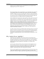
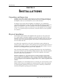
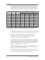
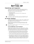
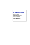
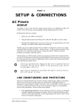
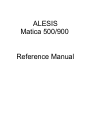
ALESIS
Matica 500/900
Reference Manual
Contents
CONTENTS
1: Introduction ............................................................................. 3
About Alesis Maticaª Amplifiers .........................................................................3
Why Another Power Amplifier? ............................................................................4
2: Installation ............................................................................... 5
Unpacking and Inspection.......................................................................................5
Physical Installation.............................................................................................5
Electrical Installation............................................................................................6
Audio Installation: Input Wiring ............................................................................7
Audio Installation: Output Wiring .........................................................................8
System Setup and Testing .......................................................................................10
3: Amplifier Operation................................................................ 13
4: In Case Of Trouble.................................................................. 15
5: Reference................................................................................. 17
Preliminary Amplifier Specifications ....................................................................17
Matica 500/900 Reference Manual
1
2
Matica 500/900 Reference Manual
Introduction
CHAPTER 1
INTRODUCTION
CHANNEL A
CHANNEL B
POWER
CLIP
CLIP
5
4
5
6
3
4
7
2
8
1
9
0
100
6
3
7
1
9
2
8
0
AC
BRKR
100
Figure 1: Amplifier front panel controls.
About Alesis Maticaª Amplifiers
Thank you for purchasing an Alesis Matica power amplifier, one of the most
advanced and highest value amplifiers available.
Your Alesis High Speed, Wide Bandwidth amplifier provides extremely accurate
sonic quality as well as measured specifications, but its conservative design and
careful attention to electronic protection means that it will continue to operate at
top condition without special attention, year after year.
Matica amplifiers use the newest generation of linear semiconductor devices for
improved performance. Their high slew rate of 80 V/ms insures that they will not
generate significant TIM (transient intermodulation) distortion. The outstanding
signal to noise ratio (typically better than 103 dB, A weighted, below rated output)
and very low harmonic distortion (typically below .009% midband) make them
ideally suited for the most critical studio monitoring applications.
These amplifiers, however, are in rugged, roadworthy packages which are of
minimum size consistent with conservative electronic design principles. Their
power transformers have unusually high current capability for their size, thus
insuring both stable power output and minimum interference with adjacent
equipment.
The CoolSyncª (patent pending) transistor cooling dynamically adjusts the rate of
front to back airflow depending on the power density of the program material, thus
anticipating the need for cooling rather than merely reacting to temperature. The
airflow cools all components, not merely the output transistors.
Detented level controls are on the front panel, where they can be easily adjusted if
necessary. Both the power switch and the circuit breaker are on the front panel so
that in case of problems, the breaker can be reset without requiring access to the
rear of the amplifier. Clip lights for each channel indicate the onset of actual
Matica 500/900 Reference Manual
3
Introduction
clipping, not just a designated output voltage which may not correspond to the
clipping point if power line voltage is low.
The rear panel inputs can be via gold plated 1/4" (6.3 mm) phone jacks, gold plated
3 pin XLR-type connectors or barrier screw terminals, all of which are standard
equipment. Outputs are on five-way binding posts which can accept large diameter
wire or 3/4" (19 mm) spaced dual banana plugs. A recessed rear panel switch allows
easy selection of stereo or bridged monaural operating modes. Separate signal and
chassis ground points are available to handle any grounding scheme.
Matica amplifiers have high current output protection relays which disconnect the
output in the event of overtemperature, DC offset, audio signals below 5 Hz on the
output terminals or excessively low line voltage. When AC power is applied to the
amplifier, the relay does not engage immediately; a 4Ð5 second delay allows the
amplifier circuitry to stabilize and prevents turn-on transients from other
equipment powering up during that time from being reproduced by the loudspeakers.
The cooling fan is also momentarily exercised at high speed at turn-on. When AC
power is turned off, the speaker protection relays immediately disconnect, thus
keeping turn-off transients from reaching the speakers. Additional protection
circuitry keeps RFI out of the audio circuits, assuring clean, stable operation in
difficult environmental conditions.
An aLinkª 25-pin connector is provided for future expansion by the user. Among the
planned accessories for attachment to this connector are outboard signal processors,
electronic crossovers and remote controllers. Also planned are an internal module to
allow soft turn-on and remote turn-on/turn-off; the internal module is for
installation by qualified personnel. See your Alesis dealer for information on these
options.
Why Another Power Amplifier?
Professional power amplifiers of today tend to fall into several groups. Those
aimed at the performing musicianÕs sound reinforcement needs are often designed for
the highest possible power output at the lowest possible price. Those intended for
portable sound reinforcement are frequently designed for minimum weight and size,
while fixed reinforcement amplifiers are often made to fit a laundry list of
requirements.
In all too many of these situations, the sonic character of the amplifier is low on
the list of design priorities. A professional amplifier must be reliable under all
circumstances, of course, because peopleÕs livelihoods and even their safety can
depend on its proper operation. And yet, the primary purpose of any audio
amplifier is reproducing sound with as high quality as possible.
The new Alesis amplifiers meet the stringent requirements of both fixed and touring
sound reinforcement, but they do not sacrifice sonic excellence to achieve their
professional credentials. Highly sophisticated engineering which takes advantage
4
Matica 500/900 Reference Manual
Introduction
of recent developments in electronic componentry, and innovative design concepts
make the Alesis power amplifiers ideal for any professional application.
Matica 500/900 Reference Manual
5
Installations
CHAPTER 2
INSTALLATIONS
Unpacking and Inspection
Carefully unpack the amplifier and inspect it for physical damage originating in
shipping. Do not discard the packing materials; they may be helpful in shipping
the amplifier when it is not mounted in a rack or other enclosure.
If damage is discovered and the amplifier was shipped to you, immediately
contact the transportation carrier and make certain that the packing materials are
preserved for inspection. You as the consignee must make any shipping claims;
neither your dealer nor Alesis can do this for you. If the amplifier was not shipped
to you, i.e. you picked it up from your dealer, contact the dealer as soon as possible
for assistance.
Physical Installation
Alesis Matica 500 and Matica 900 amplifiers take up only two rack spaces each
(3.5Ó panel height). If multiple amplifiers are mounted in the same rack, there
should be at least one rack space left between them; solid blank panels may be used
to fill the spaces, but perforated grilles used as fillers will help exhaust the hot
air from within the rack.
An exhaust fan is required in a rack with a closed back to assure sufficient air
exhaust capacity. If the rack has a door limiting access to the front panels, the door
should have ventilation grilles in it or other provisions should be made to assure a
free flow of air through the front panels of the amplifiers.
Note: Unusually high ambient or operating temperatures may cause the thermal
protection circuitry to open the internal output protection relay. Once the amplifier
has cooled, the relay will automatically close and the amplifier will resume
operation without user intervention.
While the amplifier's 14 gauge front panels are strong enough to support their
entire weight in fixed installations, Alesis strongly recommends using the Matica's
rear rack supports in all installations. Support at the rear is a must for portable and
road use.
Matica amplifiers are well shielded; however, mounting low level electronics some
distance away from power amplifiers is common practice to reduce the possibility
of electromagnetic interference into the low level units, which may sometimes be
unusually susceptible to picking up such radiation.
6
Matica 500/900 Reference Manual
Installations
Electrical Installation
One of the most important considerations for proper installation and operation of a
power amplifier is the capacity of the line feeding the mains voltage to the
amplifier. If the line does not have sufficient current capacity, the amplifier may
not be able to deliver its full rated output, both steady state and peak, with the
result that the sound character can dramatically suffer.
For best performance, assure that the power line feeding each amplifier can supply
adequate line voltage and current. Under most circumstances, normal household or
commercial power outlets will be adequate. However, when low impedance loads
are used with high maximum output power, additional current capacity may be
required.
The Audio Ground is DC isolated from the chassis, although there is an RF bypass
capacitor between Audio Ground and the chassis ground as part of the MaticaÕs RFI
protection circuitry. If a hard-wired connection between Audio Ground and the
chassis is desired, a jumper wire may be connected between the Audio Ground screw
on the input barrier strip and the adjacent ground screw on the chassis. The
amplifier is shipped with no connection between these screws, which is the
preferred method of use.
The AC cord is designed to be fed by an outlet that includes a solid earth ground.
This ground connection is an important safety feature designed to keep the chassis
of electronic devices such as the Matica amplifiers at ground potential.
Unfortunately, the presence of a ground contact in an AC socket does not always
indicate that an outlet is properly grounded. Use an AC line tester to determine
this. If the outlet is not grounded, consult with a licensed electrician.
Do not operate any electrical equipment with ungrounded outlets. Plugging a Matica
amplifier into an ungrounded outlet or ÒliftingÓ the unit off ground with a three-totwo wire adapter can create a hazardous condition. Alesis cannot be responsible for
problems caused by using Matica amplifiers or any associated equipment with
improper AC wiring.
Note: Alesis amplifiers are pre-wired at the factory for the line voltage in the
country where the amplifier is intended for sale and are supplied with appropriate
line cords. They are not readily convertible to other voltages. Before connecting
them to the power line, check to be certain that they are properly wired for use in
your country.
When wiring a rack, it is good installation practice to route all AC wiring along one
side of the rack and all audio wiring along the other side to avoid coupling ACborne interference into the audio.
Matica 500/900 Reference Manual
7
Installations
Audio Installation: Input Wiring
ALESIS CORPORATION, LOS ANGELES
SOUND REINFORCEMENT DIVISION
MATICA™ POWER AMPLIFIER
Patent Pending
MOUNT IN RACK ONLY. INSTALLER SUR SUPPORT DE MONTAGE SEULEMENT.
B
WARNING/AVIS:
MATICA INPUT
MODEL POWER
600 VA
500
900
1200 VA
120 V
OUTPUT
POWER
250 W@4W
450 W@4W
USE CLASS 2
WIRING
SHOCK HAZARD – DO NOT OPEN
´
RISQUE DE CHOC ELECTRIQUE
– NE PAS OUVRIR
TO PREVENT ELECTRICAL SHOCK DO NOT REMOVE COVERS.
NO USER SERVICEABLE PARTS INSIDE.
REFER SERVICING TO QUALIFIED SERVICE PERSONNEL.
TO REDUCE THE RISK OF FIRE OR ELECTRICAL SHOCK
DO NOT EXPOSE THIS EQUIPMENT TO RAIN OR MOISTURE.
OUTPUT
BRIDGED
MONO
A
OUTPUT
DUAL
CHANNEL
AUDIO INPUT WIRING
= TIP = PIN 2
= RING = PIN 3
= SLEEVE = PIN 1
60 Hz
FOR BRIDGED MONO
USE A INPUT
Figure 2: Amplifier rear panel controls and connections.
Warning: Be sure that the AC power is off prior to connecting or disconnecting any
signal wiring.
The input circuits of the Alesis amplifiers are electronically balanced. They may
be fed from either symmetrical (ÒbalancedÓ) or unbalanced sources. There are two
combination XLR/1/4Ó (6.3 mm) jacks provided, one for each channel, and a barrier
screw terminal strip for connecting bare wire or crimp terminals. See Figure 2.
The inputs are wired according to IEC standards:
Connection
XLR
Phone Jack
Audio Ground
Pin 1
Sleeve
High (+)
Pin 2
Tip
Low (Ð)
Pin 3
Ring
Table 1: Input Wiring
Figure 3. Balanced wiring of an XLR input connector.
Figure 4. Unbalanced wiring of an XLR input connector.
8
Matica 500/900 Reference Manual
Installations
Figure 5. Balanced wiring of a 1/4Ó (6.3 mm) three-wire phone plug.
Figure 6. Unbalanced wiring of a 1/4Ó (6.3 mm) three-wire phone plug
All input wiring should be done with shielded cable. To use an unbalanced source
with an Alesis amplifier, connect the High (+) signal wire as shown in Table 1 and
connect the shield wire to both the Low (Ð) and Audio Ground input connections. See
Figure 4 and 6. If a two-wire (tip and sleeve only) phone plug is used for an
unbalanced input, the sleeve of the plug will automatically connect the Low and
Audio Ground connections together inside the amplifier.
Long input cable runs, particularly in areas with high electrical interference,
should be done with symmetrical (ÒbalancedÓ) configuration, if possible, to lessen
the possibility of interference being picked up by the cables.
Since the input jack and barrier screws for each channel are connected in parallel,
only one of these should be used unless the same signal is to be connected in parallel
to another amplifier channel.
The input impedance of the Alesis amplifiers is 20 kW in balanced or unbalanced
configuration. Thus, the inputs of several amplifiers may be connected in parallel if
desired. The maximum number of amplifier channels will depend on the minimum
output load impedance of the device feeding the amplifiers. For example, if the
minimum output load impedance of the source device is 600ÊW, up to 30 amplifier
channels may be connected to it in parallel without overloading the source deviceÕs
output.
To use the amplifier in Bridged Mono mode, connect the input signal to Channel A
only and move the recessed slide switch to the Bridged Mono position. The Channel
B input will be inactive. See below for output wiring in Bridged Mono configuration.
Audio Installation: Output Wiring
Warning: Be sure that the AC power is off prior to connecting or disconnecting any
signal wiring.
Alesis amplifiers can reliably drive 2 W loads in Stereo mode and 4 W loads in
Bridged Mono mode. However, the impedance of a loudspeaker varies with
frequency, and its nominal rated impedance is not necessarily its minimum
impedance. Some loudspeakers carry both nominal and minimum impedance
specifications, and some are supplied with impedance curves. When connecting
Matica 500/900 Reference Manual
9
Installations
multiple loudspeakers or systems to any amplifier, care should be taken that the
actual load impedance does not drop below the amplifierÕs rated output load.
Alesis amplifiers will not be damaged by excessively low output load impedances,
but they will not be able to provide full output power and their protection circuits
may automatically cut off their outputs until the low load condition is removed.
Gauge
Diameter
DC Resist./
Cable Length Resulting in a 1 dB Power Loss
(AWG)
(Solid)
30 m (100Õ)
6
4.12 mm
0.08 W
366 m
1200Õ
740 m
2400Õ
8
3.26 mm
0.13 W
244 m
800Õ
488 m
1600Õ
10
2.59 mm
0.20 W
145 m
475Õ
290 m
950Õ
12
2.05 mm
0.32 W
91 m
300Õ
182 m
600Õ
14
1.63 mm
0.52 W
58 m
190Õ
116 m
380Õ
16
1.29 mm
0.82 W
37 m
120Õ
74 m
240Õ
18
1.02 mm
1.32 W
23 m
75Õ
46 m
150Õ
20
0.81 mm
2.08 W
15 m
50Õ
30 m
100Õ
22
0.64 mm
3.30 W
9m
30Õ
18 m
60Õ
4 W Load Impedance
8 W Load Impedance
Table 2: Speaker Cable Losses. Values are calculated based on the sum of the length of both
conductors. Note that a 1 dB power loss is equivalent to 12% of the amplifier power.
The wire thickness or gauge should be chosen according to the load impedance and the
length of the wire run from the amplifier to the loudspeaker terminals. See Table 2.
Because the wireÕs resistance to the flow of current is in series with the
loudspeaker, a wire with lower resistance will deliver more power to the
loudspeaker; also, the amplifier will be able to control the loudspeakerÕs
movement betterÑthis latter is called Òdamping factor.Ó
ItÕs interesting to observe that an amplifierÕs rated damping factor is essentially
unrealizable unless the loudspeaker is connected directly to the amplifierÕs output
terminals without any interconnecting cables. For example, a typical installation
using 20 feet (6 m) of 16 AWG wire connecting an amplifier and an 8 ohm speaker
will result in a damping factor of 23.5 with a perfect amplifier; with a real world
amplifier, the damping factor will be even lower.
Many special cables are sold for use with audiophile and studio loudspeakers. We
make no recommendations for cables other than that there be sufficient copper in
them to keep the total resistance acceptably low.
Loudspeaker outputs for both channels are on heavy-duty five-way binding posts
which can accept single or dual banana plugs, bare wire or terminals. See Figure 2
above. Note the unique in-line configuration of these binding posts.
10
Matica 500/900 Reference Manual
Installations
Banana plugs are inserted in the ends of the plastic insulating nuts on each output
terminal. The terminals are spaced to accept standard 3/4Ó (19 mm) spaced dual
banana plugs. Alternately, the insulating nuts may be loosened so that stranded or
solid wire may be attached. The threaded posts under the nuts have holes in them
which can accept fairly heavy gauge wire, but if the wire does not fit through the
hole, it may be wrapped around the post. In either case, the nut should be snugly
tightened to secure the wire in place.
Caution: Be sure that no stray wire strands accidentally touch an adjacent wire or
terminal. Lightly tinning the end of a stranded wire with solder after the strands
are twisted together will help prevent it from fraying and will insure that all
strands are connected, but be careful when tightening or stressing the wireÑtinned
wires may be brittle.
If a crimp lug terminal is used on the speaker wire and the lug is too small to fit onto
the threaded post, one leg of the terminal may be inserted in the hole in the post.
As with wire connections, make certain that the terminal is snugly attached by
tightening the plastic insulator nut.
A positive voltage applied to the High (+) side of either input when the amplifier
is in Stereo mode will result in a positive voltage appearing on the Red (+)
terminal of the corresponding output channel.
When connecting the output of the amplifier in Bridged Mono mode (assuming that
the input has been connected to Channel A and the Stereo/Mono rear panel switch
has been set to Mono), the loudspeaker wires are connected to the two center
terminals only. Note that, unlike amplifiers from some other manufacturers,
Bridged Mono connections are to Red and Black terminals, not to two Red or two
Black terminals. Do not connect anything to either of the two outer terminals.
In Bridged Mono mode, applying a positive voltage to the High (+) side of the
Channel A input connection will result in a positive voltage on the Red output
terminal (Channel A +).
Note that Channel B of each Matica amplifier is internally inverting, which
assures the maximum possible low frequency output when both channels are driven.
Connecting the wiring as described above will keep the input to output signal
polarity consistent. However, the Black terminals of Channels A and B are not at
the same potential and must not be connected together. Some loudspeaker switching
systems and many headphones use common wiring for the low sides of both
channels; these systems cannot be used with Matica amplifiers unless the alternate
wiring instructions below are followed.
Operation with a common output wiring is possible by connecting the black output
binding post of the A channel to the red post of the B channel. This is now the
common speaker or headphone output lead and is at ground potential. The
remaining red and black posts are the Channel A and B "hot" connections
respectively.
Next, the audio input to the amplifier must be from a balanced source. Wire the A
Channel balanced input wiring with normal polarity but wire the B Channel's
input with the Polarity inverted.
Matica 500/900 Reference Manual
11
Installations
What we're doing here is compensation for the fact the Matica's B Channel is
normally internally inverted and then re-inverted at its output. This improves the
amplifier's ability to respond to high power low frequency signals better than
conventional amplifiers. The input and output wiring changes above "invert the
inversion" so the net effect is proper signal polarity and amplification with the
ability to operate both channel's outputs tied to a common speaker lead.
System Setup and Testing
Before applying power for the first time, double check the wiring to insure that
everything is firmly connected and that the proper signals are being fed to the
proper places. If a low frequency signal in a multi-amplified system is applied to a
high frequency transducer, the transducer can be damaged, and a loose connection
can cause noise which can damage any transducer.
Be certain that the amplifier front panel gain controls are set to minimum when the
system under test is first powered up. After the power is applied, slowly advance
each gain control to confirm that there are no driver-destroying hums or buzzes
presentÑif there are, turn the power off and locate the source of the difficulty.
When first applying program material to the system, it is also advisable to keep
the gain controls turned down to confirm, once again, that the wiring is correct. Once
the system wiring is determined to be correct, the gain controls can then be set to an
appropriate level for the system gain structure.
Setting the system gain is fairly straightforward, but if it is not properly adjusted,
the systemÕs distortion and noise characteristics may be less than optimum. The
input sensitivity of the Alesis amplifiers is 0.775Êvolts (0ÊdBu) for rated output
with the amplifier gain controls at maximum. If the signal at the amplifier input
is higher than this, the input gain controls must be turned down to avoid amplifier
clipping.
It is generally best to try to keep the gain of the source device balanced for best
signal-to-noise ratio consistent with distortion and to turn down the amplifier
inputs to reduce the amplification of noise artifacts originating prior to the signalÕs
reaching the amplifier.
The maximum level at the amplifierÕs input terminals is +22 dBu (10ÊVÊRMS). It is
possible that the output signal from the source may be too high and, thus, distorted
before it reaches the amplifier gain control, either because the source device is
clipping or the amplifier input stage is overloaded. In either case, no amount of
level control adjustment at the amplifier can remove this distortion, and the device
feeding the amplifier should have its gain lowered until the level is within proper
bounds.
It is also possible, particularly when using very efficient loudspeakers, that the
sound level from the loudspeakers may be too high when the amplifier is driven to
full output. In such cases, leaving the amplifier gain at maximum and turning down
the signal sourceÕs output level can result in audible noise products in the signal
coming from the source device or wiring. As above, keeping the source level as high
as possible and lowering the amplifier input gain will keep the noise level at a
minimum.
12
Matica 500/900 Reference Manual
Installations
Matica 500/900 Reference Manual
13
Installations
CHAPTER 3
AMPLIFIER OPERATIONS
Once all gain adjustments are made and proper operation is confirmed, no special
considerations are required for Matica amplifiers. Aside from the front panel gain
controls, there are no user adjustments or routine maintenance operations necessary
(or available).
When powering a system on or off, it is usually advisable to turn on the power
amplifiers last and to turn them off first, so that any turn on or turn off transient
signals generated by other equipment in the system are not amplified and sent to
the loudspeakers. However, Matica amplifiersÕ protection relays have a 4 to 5
second turn-on delay which keeps the loudspeakers disconnected while the system
is powering up. These relays also disconnect the load very quickly when power is
removed from the amplifiers, thus minimizing the chance that turn-off transients
originating elsewhere in the system will be sent to the speakers.
14
Matica 500/900 Reference Manual
Installations
Matica 500/900 Reference Manual
15
In Case of Trouble
CHAPTER 4
IN CASE OF TROUBLE
No Sound
¥Is the power switch on? If not, turn it on.
¥Is the power light on? If not, confirm that the amplifier
is plugged into a live AC mains circuit of appropriate
voltage and current capacity.
¥Check the circuit breaker and reset it if it is open. If the
breaker opens immediately, there may be a short
circuit across the output terminals; if not, there is a
possible internal fault in the amplifier which will
require service by a qualified technician.
¥Is the amplifier input connected to a live signal source?
Is the loudspeaker solidly connected to the amplifier
output at both ends of the speaker cable? Is the
speaker faulty?
¥Is the amplifier very hot? Is the ambient temperature
and/or the air flow in the rack abnormal? If so, the
amplifier may be in thermal protect mode; normal
operation will resume when its internal temperature
has dropped to reliable levels.
Weak or Distorted Signal
¥Is the signal source working correctly?
¥Is the wiring to the amplifier input properly connected
at both ends?
¥Have the gain controls of the signal source or the
amplifier been moved since the system was set up?
16
Matica 500/900 Reference Manual
In Case Of Trouble
Hum and/or Noise
¥Is the signal source working correctly?
¥Are the systemÕs electrical and audio ground connections
proper?
¥Are there any noise-producing sources on the AC mains
circuit, such as light dimmers, motors, etc.? If so, it
may be necessary to run a separate power line for the
audio equipment.
Thin or Muffled Sound
¥Are the loudspeakers all working properly, or are one or
more drivers defective?
¥In a multi-amplified system with a low level crossover
network, are all outputs from the network operating
properly? Are all loudspeakers properly connected?
¥Are both sides of a balanced input solidly connected? Is
the low side of the amplifier input connected to Audio
Ground with an unbalanced input connection?
Audio Cuts In and Out
¥Is the signal at the amplifier input terminals good?
¥Are all the input and output wires solidly connected?
¥If the sound cuts out for a minute or two and then returns,
is the amplifier overheating and cycling through
thermal protect mode? If so, check for short circuits in
the output wiring or excessive ambient temperature.
Channel B Shows Heavy
Clipping, Channel A is OK.
¥The two black output binding posts have been connected
together. These terminals are not at the same
potential and cannot be connected without special
wiring consideration. See page 10.
Matica 500/900 Reference Manual
17
In Case of Trouble
CHAPTER 5
REFERENCE
Preliminary Amplifier Specifications
8W
4W
2W
8W
4W
2 Channel
2 Channel
2 Channel
Bridged
Bridged
Matica 500
162 W
250 W
350 W
500 W
650 W
Matica 900
270 W
450 W
680 W
900 W
1350 W
Power Output*
*Typical, 1% THD @ 1 kHz; two-channel ratings are for each channel, with both channels driven to rated output.
Frequency Response:
10 Hz Ð 80 kHz, +1, Ð3 dB (Ð0.1 dB @ 20 kHz)
Slew Rate:
80 V/ms (two channel), 160 V/ms (bridged mono)
THD:
0.009% @ 1 kHz, 4 W load
Hum and Noise:
Better than 103 dB below rated output, A weighted
Input Sensitivity:
0.775 V RMS for rated power
Input Impedance:
20 kW, balanced or unbalanced
Cooling System:
CoolSyncª (patent pending) cooling fan speed controller
with additional secondary high speed mode. Front to rear
airflow cools all internal components
Controls, Indicators and
Connectors:
Front Panel:
18
Rocker style high inrush power switch, manually resettable
circuit breaker, green LED power indicator, individual
detented level controls and individual red LED clip
indicators
Matica 500/900 Reference Manual
In Case Of Trouble
Rear Panel:
Balanced gold plated 1/4Ó (6.3 mm)/latching XLR-type
input connectors, slotted/Phillips screw terminal barrier
input connector, heavy gauge 5-way binding post output
connectors, recessed stereo/bridged mono slide switch, DB-25
aLinkª accessory connector and mounting holes for accessory
boxes, strain relieved line cord, chassis ground connection
screw
Dimensions:
3 1/2Ó x 19Ó (2U) panels
Matica 500: 12 1/4Ó (311 mm) depth
Matica 900: 16 1/8Ó (410 mm) depth
Net Weight:
Matica 500: 30 lb (13.6 kg)
Matica 900: 48 lb (21.8 kg)
Chassis Construction:
14 gauge black powder-coated steel construction with
integral front and rear rack mounts. All controls, connectors
and hardware on all surfaces recessed for protection.
Matica 500/900 Reference Manual
19