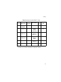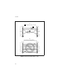
1
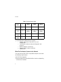
Allied Telesyn
Ethernet Network Adapter
For MCA Bus Computers and IEEE 802.3 Compliant LANs
User Manual
AT-1720T for Twisted Pair Media
AT-1720AT for AUI Port Adapter and Twisted Pair Media
AT-1720BT for Thinnet Coaxial and Twisted Pair Media
AT-1720FT for Fiber Optic and Twisted Pair Media
i
AT-1720
Warranty: Your Allied Telesyn CentreCOM™ Ethernet Network Adapter has a lifetime
warranty. Refer to the warranty card supplied with the product for the full Warranty
Statement.
Trademarks: CentreCOM is a registered trademark of Allied Telesyn. Ethernet is a
registered trademark of Xerox Corporation. Novell and NetWare are registered
trademarks of Novell, Inc. Microsoft and MS-DOS are registered trademarks and LAN
Manager and Windows for Workgroups are trademarks of Microsoft Corporation.
UNIX is a registered trademark of UNIX System Laboratories. 3Com is a registered
trademark of 3Com. PC-NFS is a trademark of Sun Microsystems, Inc. PC/TCP is a
registered trademark of FTP Software, Inc.
Copyright 1994 Allied Telesyn International, Corp. All rights reserved. No part of this
publication may be reproduced without prior written permission from Allied Telesyn.
Allied Telesyn reserves the right to make changes in specifications and other
information contained in this document without prior written notice. The information
provided herein is subject to change without notice. In no event shall Allied Telesyn
be liable for any incidental, special, indirect, or consequential damages whatsoever,
including but not limited to lost profits, arising out of or related to this manual or the
information contained herein, even if Allied Telesyn has been advised of, known, or
should have known, the possibility of such damages.
FCC Warning: This equipment has been tested and found to comply with the limits
for a Class A digital device pursuant to Part 15 of the FCC Rules. These limits are
designed to provide reasonable protection against harmful interference when the
equipment is operated in a commercial environment. This equipment generates,
uses, and can radiate radio frequency energy and, if not installed and used in
accordance with this instruction manual, may cause harmful interference to radio
communications. Operation of this equipment in a residential area is likely to cause
harmful interference in which case the user will be required to correct the interference
at his own expense.
All Countries: Install in accordance with Local and National Electrical Code.
Canadian Radiation: This digital apparatus does not exceed the Class A limits for
radio noise emissions from digital apparatus as set out in the radio interface
regulations of the Canadian Department of Communications.
Lé présent appareil numérique n'émet pas de bruits radioélectriques dépassant les
limites applicables aux appareils numériques de le Classe A. Prescrites dans le
réglement sur le brouillage radioélectrique edicté par le ministére des
Communications Du Canada.
ii
CONTENTS
Chapters:
1
2
3
4
5
Overview ..........................................................................................................
What You Get From Us ....................................................................................
What Else You Need to Connect to the Network ..............................................
Installation ......................................................................................................
Summary of Installation Steps ..........................................................................
OS/Environment-Specific Installation Information ............................................
Boot ROM Socket .............................................................................................
Network Adapter Card Drivers ..................................................................
Drivers for Workstations ...................................................................................
Drivers for Servers ............................................................................................
Driver Installation ..............................................................................................
Support for Multiple Adapter Cards ..................................................................
Cabling .............................................................................................................
Important 10BASE-T Cable Considerations .....................................................
10BASE2 RG58/BNC Cabling ..........................................................................
10BASE-FL/FOIRL (Fiber Optic) Connection ...................................................
10BASE5 (AUI) Connection .............................................................................
Communication Status Indicators .....................................................................
Troubleshooting ............................................................................................
Identify the Exact Symptoms ............................................................................
Experiment with Possible Solutions ..................................................................
Get Technical Support ......................................................................................
1
1
2
5
5
6
13
15
15
16
17
20
21
21
25
26
27
29
31
31
32
33
iii
Chapter 1
Overview
What You Get From Us
When opening this Allied Telesyn product, make sure that the
package you have received is complete and in good condition. The
package should include:
❑ This manual which contains:
— Information to install, configure and troubleshoot the
adapter card, the card driver and the network
operating system
— The technical support fax order form
— Warranty/registration cards
❑ An Ethernet® network adapter card
The Allied Telesyn AT-1720 16-bit Ethernet Adapter Card
provides a Micro Channel Architecture (MCA)-bus PC
access to an Ethernet Local Area Network (LAN) for
communicating and sharing computer resources. The
AT-1720 offers full compliance with IEEE 802.3
specifications.
The AT-1720 adapter card family supports the 10BASE-T,
10BASE2, 10BASE5 and 10BASE-FL network media as
shown in Table 1.
1
AT-1720
Table 1: Supported Network Media
Card
Model
10BASET
AT-1720T
10BASE2
10BASE5
10BASE-FL
Supporte
d
N/A
N/A
N/A
AT1720AT
Supporte
d
Supported
with
transceiver
Supported
with
transceiver
Supported
with
transceiver
AT1720BT
Supporte
d
Supported
N/A
N/A
AT1720FT
Supporte
d
N/A
N/A
Supported
❑ The CardAssistant diskette which contains:
— Adapter Description Files (ADF) for card
configuration
— CardAssistant software setup and diagnostic test
program
— Network adapter card drivers
— Support files for network software
— Readme files
What Else You Need to Connect to the Network
You must have an IBM PS/2 or compatible computer that meets
the following requirements:
❑ An MCA bus computer
❑ Approximately 32K of available RAM for the driver, depending
on the driver installed
2
Overview
❑ 512K of available RAM when running Allied Telesyn
CardAssistant setup/diagnostics software
❑ A free 32-byte block of I/O at 0400h, 1400h, 2400h, 3400h, 4400h,
5400h, 6400h or 7400h
❑ An available interrupt (IRQ 3, 4, 5, 9, 10, 11, 12 or 15)
❑ Compatible workstation operating system and network system
software
In addition to your workstation hardware, you must provide
network operating system software like Novell® NetWare,
Microsoft® LAN Manager, Sun® PC-NFS, or Banyan® VINES.
You must also provide the necessary cables, connectors and
terminators.
In summary, your networked PC will function properly on the
network if the following are true.
— You have a network adapter card in your PC
— The adapter card has a unique I/O and boot ROM
addresses, and IRQ
— You have network software installed
— Your adapter card is properly connected to the
network
— You have a driver installed for your particular
network software/network adapter card combination.
3
Chapter 2
Installation
Summary of Installation Steps
Installation of your Allied Telesyn network adapter card is
simple and quick. Generally, the installation of one network
adapter card with common software on PS/2 MCA bus or
compatible workstations is mostly automated. This chapter also
gives procedures for more complex installations.
The following list of steps for the simplified Allied Telesyn
network adapter card hardware/software installation is
explained in greater detail later in the chapter.
1. Installing the adapter card in an MCA slot:
Physically install the card in the computer’s card cage.
2. Installing option files:
These are Allied Telesyn files called “option” files by your
MCA-bus installation software, which installs them.
3. Configuring the adapter card:
This process is done by your MCA-bus installation
software, automatically or manually.
4. Saving configuration to the system partition:
This creates a backup of your system configuration in your
computer’s system partition.
5
AT-1720
OS/Environment-Specific Installation Information
Accurate and current network hardware and software
installation information changes with every network software
package, protocol stack or operating system. To respond quickly
and accurately to these changes, we have included the latest
installation information in a series of applications and OS specific
readme files on the Allied Telesyn CardAssistant diskette.
The file \READ.ME, on the CardAssistant diskette, contains a
guide to current readme files on that diskette, and is
recommended reading for the installer.
Installing the adapter card in an MCA slot
Refer to the computer’s manual for information on installing
card-cage accessories.
Warning
High voltages inside the computer present a safety
hazard. Make sure the power is OFF before
removing the cover.
Caution
This LAN adapter card is for use only with IBM
PS/2 or compatible UL listed personal computers
that have installation instructions detailing
installation of card-cage accessories. Installation
should be performed with precautions to prevent
damage to static-sensitive components.
!
6
Installation
1. Make sure the computer’s power is turned OFF.
2. Pick the card slot you wish to use. Follow the
manufacturer’s instructions for adding a card.
TIP: When installing the AT-1720FT temporarily remove the shields from
the fiber-optics cable connectors to give the connectors more clearance.
Do not turn ON your computer.
Installing option files
To install the Allied Telesyn option files on your computer’s hard
disk, this procedure uses the computer manufacturer’s special
“option copy” software and procedures. Typically, the computer
manufacturer will refer to the Allied Telesyn files as “option”
files, which are on the “option disk,” the Allied Telesyn
CardAssistant diskette.
1. To copy the option diskette, verify that all floppy disk
drives are empty. Turn the computer ON. In a few seconds,
one of two things happens. Either:
a.
The Configuration Error screen with automatic
configuration prompt appears, because the computer
senses that its hardware has changed since the last
time it was turned ON. In this case, go straight to
Step 2.
Or:
b. The screen displays only a RAM-OK count and an
error number, and stops. In this case, turn the machine
OFF, insert the computer manufacturer’s reference
diskette into drive A:, turn the machine ON and go to
Step 2 when you see the automatic configuration
prompt.
7
AT-1720
2. At the “Automatically configure the system? (Y/N)”
prompt, answer N for no, and the Main Menu will appear.
Do not answer Y here, or you will have to reset your
computer to get back to this point.
3. Select the “Copy an option diskette” option, and follow
the procedure to completion.
4. Remove the Allied Telesyn diskette from the floppy drive.
Configuring the adapter card (auto-configure)
1. Verify that all floppy drives are empty if you followed Step
1a on page 7. If you followed Step 1b in the previous step,
place the computer manufacturer’s reference diskette in
drive A:.
2. At your computer’s keyboard, hold down the CTRL (control)
and ALT keys, and press the DEL (delete) key. This will
reset your computer. The first screen you see will be the
Configuration Error screen of the configuration installation
step.
3. This time, when asked “Automatically configure the
system? (Y/N)” answer Y for yes. A screen message
informs you when the configuration process is completed.
4. After you have completed configuring your system for the
adapter card, verify that your floppy drives are empty, and
re-boot your computer.
Configuring the adapter card (manual configure)
1. Boot your computer as in “Installing option files” Steps 1a
or 1b on page 7.
2. In the Main Menu, select the “Set Configuration” menu.
3. In the “Set Configuration” menu, select “Change
Configuration.”
8
Installation
4. Scroll through the Change Configuration window to view
all the configuration attributes of the Allied Telesyn
AT-1720 adapter card. A list of those attributes and your
choices is found in Table 1.
5. Change the configuration attributes as necessary. The
configuration software does not allow you to set adapter
card values that conflict with the rest of your system.
6. After you have completed configuring your system for the
adapter card, verify that your floppy drives are empty, and
re-boot your computer.
Table 1: Adapter Card Attributes and Choices
Attribute
Choices
Meaning
Interrupt request
number
I/O Port
Addresses
IRQ 3, 4, 5, 9,
10, 11, 12 or 15
0400h, 1400h,
2400h, 3400h,
4400h, 5400h,
6400h, 7400h
C4000 to
DC000
Disabled
Twisted Pair
AUI (AT)
BNC (BT)
Fiber (FT)
Autoselect
Use interrupt 3, 4, 5, 9, 10, 11, 12 or 15
to signal CPU
Locate I/O port at selected address
range
Boot ROM
memory address
AT-1720AT, BT,
or FT
Port
Selection
Twisted Pair
Type Select
100Ω UTP/STP
150Ω STP
Locate boot ROM start at selected
address
Disable boot ROM
Select 10BASE-T port
Select 10BASE5 port
Select 10BASE2 port
Select 10BASE-FL port
Selects other-media port if 10BASE-T
cable not present
Select Level 3, 4 or 5 10BASE-T cable
Select IBM type 1 10BASE-T cable
9
AT-1720
Saving configuration to system partition
1. Boot your computer as in “Installing option files” Steps 1a
or 1b, on page 7.
2. In the Main Menu, select the “Set Configuration” menu.
3. To backup the configuration you just completed, select
“Set configuration,” and from that menu, select
“Backup configuration.” When the backup is complete (a
few seconds) press ENTER to accept the backup, F3 to go to
the Main Menu, and F3 to exit.
If the installation has been successful up to this point, go to
Chapter 3, “Network Adapter Card Drivers.” If you experience
difficulties, and need to run card diagnostics or view
configuration parameters, invoke the CardAssistant program.
Invoking CardAssistant
Note
The CardAssistant software may not be used to
modify adapter card parameters. To change these
parameters, you must use your computer
manufacturer’s configuration software.
1. Insert the installation diskette into the appropriate floppy
drive.
2. Type:
floppydrive:\setup17
where floppydrive is the disk drive containing the
CardAssistant program. Proceed to Step 4.
10
Installation
3. CardAssistant is copied onto a hard drive when you install
the driver for the adapter card. Once this is accomplished,
you can type:
path\setup17
where path\ is the optional drive and directory.
4. The Main Menu appears and you are ready to select one of
the icons.
Working with CardAssistant menus
You can use either the keyboard or mouse to make menu
selections.
CardAssistant’s Main Menu presents you with the choice of
installing a driver, viewing the card configuration or running
diagnostics. The message window under the menu lists available
commands.
Running diagnostic checks with CardAssistant
Note
Invoking the CardAssistant program requires that
the card be present. If you have a driver running,
you will not be allowed to open the Diagnostics
window. If you must run diagnostics, you must first
comment out the driver line in the batch file (for
NetWare) or the DEVICE=drivername line in
config.sys (for an NDIS driver) and restart the
PC.
1. Invoke CardAssistant if necessary. See “Invoking
CardAssistant” on page 10.
2. Select the Diagnostics menu. Type:
D
ENTER
.
11
AT-1720
The CardAssistant diagnostic routines test the board and the
configuration for functional problems. The routines are:
❑
❑
❑
❑
❑
❑
PC bus interface
On-board RAM
Interrupt test
Internal loopback
MAC address
Boot ROM
The diagnostic routines display whether the card passed each
test.
You can see if the board passes before connecting the computer
to the network, and then confirm that it still passes after the
network connector is plugged in. This method can help you
isolate a problem.
Viewing AT-1720 configuration with CardAssistant
1. Invoke CardAssistant if necessary. See “Invoking
CardAssistant” on page 10.
2. Select the Configured I/O Parameters View menu.
Type:
C
ENTER
.
The displayed I/O parameters are read-only, and may not be
modified with CardAssistant.
Installing more than one card
You can install up to four Allied Telesyn adapter cards in the
same computer. Each requires its own unique I/O resources (I/O
port and IRQ).
12
Installation
If more than one card is installed and configured in the host when
you run CardAssistant, the configuration window displays a
column of settings for each. You can tell which column is for
which card by checking the node address. The node address
displayed agrees with the label on the card itself.
Boot ROM Socket
The AT-1720 card is shipped with an unpopulated boot ROM
socket. For a diskless workstation, the card needs a boot ROM to
allow it to load the operating system over the network. If a ROM
is installed, the Boot ROM Enable switch must be set with your
computer manufacturer’s configuration software, by selecting a
ROM base address.
Boot ROMs are application-specific. Allied Telesyn supplies a
range of boot ROMs for different network environments.
Contact your Allied Telesyn representative for more
information.
13
Chapter 3
Network Adapter Card Drivers
Because user network environments are numerous, differing in
network-management software, operating systems, and protocol
stacks, a variety of adapter card drivers is necessary to operate
an adapter card in a majority of environments. An ODI driver for
NetWare running in DOS might be needed, or an NDIS driver
for Windows for Workgroups or for LAN Manager running in
OS/2, or a packet driver for PC/TCP in DOS.
The CardAssistant diskette has adapter card drivers for many
different environments, as well as application-specific readme
files and sample configuration files. Depending on your network,
you will need to install the right driver and possibly merge it
with your network software. Refer to the manuals supplied with
your network software for the procedure for installing an
adapter card driver. Allied Telesyn maintains application
information on our bulletin boards. See “Get Technical Support”
on page 33.
Drivers for Workstations
If you are installing the adapter card in a workstation, see the
workstation driver selection in Table 2. This table contains only
the most commonly used workstation drivers. Allied Telesyn
continually adds new drivers for both servers and workstations,
and a complete list and description of these drivers is contained
in the file \READ.ME on the CardAssistant diskette.
15
AT-1720
Table 2: Most Commonly Used Workstation Drivers
Network Software
Card Driver Path\Filename
NetWare for DOS1
NetWare Lite1
Windows for Workgroups
LAN Manager 2.x for DOS1
LAN Manager 2.x for OS/21
PC/TCP-compatible TCP/IP
\DOS\AT17ODI.COM
\DOS\AT17ODI.COM
\AT1700.DOS
AT1700.DOS2
AT1700.OS23
\PKTDRV\AT1700.COM
NOTE 1. Installable by CardAssistant
NOTE 2. Driver in subdirectory \MSLANMAN.DOS\DRIVERS\ETHERNET\AT1700\
NOTE 3. Driver in subdirectory \MSLANMAN.OS2\DRIVERS\ETHERNET\AT1700\
Drivers for Servers
If you are installing the card in a server, refer to Table 3 for
driver selection.
Table 3: Most Commonly Used Server Drivers
Network Software
Card Driver Path \Filename
NetWare v4.01
NetWare v3.111
NetWare v3.121
NetWare v2.21
\NETWARE.40\AT1700.LAN
\NETWARE.386\AT1700.LAN
\NETWARE.386\AT1700.LAN
\xAT1700.OBJ
(x = A, B, C, or D)
\xAT1700.OBJ
(x = A, B, C, or D)
AT1700.OS2 2
NetWare v2.151
LAN Manager 2.x for OS/2
NOTE 1. Installable by CardAssistant
NOTE 2. Driver in subdirectory \MSLANMAN.OS2\DRIVERS\ETHERNET\AT1700\
16
Network Adapter Card Drivers
Driver Installation
The procedures for installing, binding or merging these drivers
with the network software vary with the operating system type
and version. For detailed instructions, refer to the LAN
administration manuals for your network software.
TIP: Network software manufacturers’ procedures and file structures are
subject to change. This is why the adapter card manual can only provide
general guidelines on installing drivers. Additional, more up-to-date
installation notes may be found in the readme files on the CardAssistant
diskette. But for accurate, detailed information on network installation,
your network software manuals are your best source.
General steps for copying a driver to your system
Use the setup program on the CardAssistant diskette to copy
the driver.
1. Insert the diskette into the floppy disk drive and type:
floppydrive:setup17
ENTER
where floppydrive is the disk drive containing the
installation diskette.
2. Select the “Installation” icon on the main menu.
3. Choose the appropriate driver from the menu choices. If
the driver you need is not listed, get help from the READ.ME
file on the CardAssistant diskette.
Following the instructions on the screen, copy the driver to
a standard directory (for example LAN Manager
customarily uses C:\LANMAN\DRIVERS\ETHERNET for a
server). The CardAssistant program will create the
directory if it does not already exist and copy the necessary
files. Exit the CardAssistant program.
17
AT-1720
4. Complete the installation of the network software, and
review all configuration files to verify that they match the
card’s configuration.
Updating a Novell IPX workstation to ODI
Individual Novell IPX workstations on NetWare systems are
frequently converted to Novell Open Data-Link Interface (ODI)
workstations running on the same system. This conversion is
typically made because Novell no longer supports the IPX
specification, and has replaced it with the ODI specification.
Therefore, changing or updating network adapter hardware or
software on an IPX workstation will probably involve changing
the driver type from IPX to ODI.
Note
The IPX-ODI change in no way impairs the
workstation’s ability to function with your original
NetWare software on the original, unchanged
network.
1. Run CardAssistant (setup17.exe) and follow the
instructions for Install System Software, choosing
Netware DOS Workstation (ODI) in the driver install
field. CardAssistant, in its default mode, creates a directory
called \NET on the workstation disk drive, copies NET.CFG,
NETX.EXE, AT17ODI.COM, IPXODI.COM and LSL.COM files to
that directory. Copying these files to your hard drive
completes the ODI installation.
2. Exit CardAssistant.
3. Use your computer manufacturer’s configuration software
to configure the adapter card and backup the configuration
information. Record the configuration information on the
LAN Management Summary/Quick Reference Guide card
for future reference.
18
Network Adapter Card Drivers
4. Exit the manufacturer’s configuration software.
Note
The word “Slot” in the following step, must be
indented from the left margin under the Link Driver
line by at least one space or one tab.
5. Open the ASCII file NET.CFG with a text editor and verify
that the following lines are there:
Link Driver AT17ODI
Slot x
where x corresponds to the computer’s card cage slot
number.
6. The batch file, e. g., AUTOEXEC.BAT, that you use to get on
the network must contain these lines in the following order:
LSL
AT17ODI
IPXODI
NETX
F:
login
7. Now reboot the computer to load the new configuration,
and look for the driver's log-on message.
Installing NDIS for TCP/IP
AT1700.DOS is the AT-1720 adapter card driver based on the
Network Driver Interface Specification (NDIS) developed by
Microsoft and 3Com. It is used for Microsoft LAN Manager
applications, as well as implementations of Transmission Control
Protocol/Internet Protocol (TCP/IP) such as PC-NFS from Sun
Microsystems.
19
AT-1720
AT1700.COM conforms to the Packet Driver specification
developed by FTP Software. It can be used for implementations
of TCP/IP such as PC/TCP, concurrent with other protocol
stacks.
Note
Although the Allied Telesyn drivers support multiple
protocol stacks, it is important to have only one stack
of a given type resident. For example, if you use the
public domain IP protocol driver PROTMAN.SYS, you
should not use another TCP/IP stack concurrently.
More information on installing the NDIS driver and the packet
driver in different environments is available in the readme files
on the CardAssistant diskette.
Support for Multiple Adapter Cards
You can have up to four AT-1720 adapter cards in a single
computer (workstation or server). Each needs its own driver
loaded (or the same driver loaded on a re-entrant basis). Consult
your network software documentation for instructions on
binding the drivers.
20
Chapter 4
Cabling
For complete rules of cabling and for information useful in
planning network configurations, see ISO/IEEE Publication
8802-3. The AT-1720T is for use with 10BASE-T segments, using
an 8-wire (4-pair) RJ45 jack for the network cable, shown in
Figure 1.
Figure 1:
AT-1720T UTP Port and RJ45
Connector
Important 10BASE-T Cable Considerations
A serious problem exists concerning identification of modular
cable for 10BASE-T connections. There are various grades of
voice-quality and data-quality cables. These can appear to be
similar externally, and their DC characteristics are also similar.
However, their AC characteristics are radically different, and
therefore high-speed data transmission characteristics are not
interchangeable.
21
AT-1720
The identification problem is exaggerated by the fact that some
suppliers have sold purportedly data-quality cables
manufactured with voice-quality cabling.
If any voice-quality cabling is used in a 10BASE-T network
segment, data movement is slow, collision-prone or non-existent.
To confuse the issue, the Link indicator on the interface will
usually indicate a valid link in such a case.
For the foregoing reasons, it is absolutely vital that all cabling
used with the 10BASE-T adapter card connections is of level 3, 4,
5 or IBM type 1. As a rule of thumb, if a cable type is flat, it is
typically untwisted and will cause problems. If a cable is more or
less round in section, it will typically work.
The six common modular cable specifications and their
applicability to 10BASE-T network use are shown in Table 4,
and cable schematics are shown in Figure 2.
22
Cabling
Table 4: Usable and Unusable 10BASE-T Cable
Cable
Level
Cable
Description
AC
Character
Specification
Twist/ 10BASE-T
Foot
OK?
1
Unshielded
untwisted
N/A
CCITT
N/A
NO!
2
Individual UTP
100Ω ± 30Ω
RS232
1BASE5
AT&T PDS
N/A
NO!
3
Typical
individual UTP
100Ω ± 15Ω
TI, AT&T ISDN
10BASE-T
IBM Type 3
3-5
YES
4
Enhanced
individual UTP
100Ω ± 30Ω
EIA, TIA
10BASE-T
NEMA
5-8
YES
5
Individual STP
100Ω ± 30Ω
EIA, TIA
10BASE-T
8-10
YES
IBM
Type 1
Individual STP
150Ω
PCC FT 1
N/A
YES1
NOTE 1. To use IBM Type 1 cable, the 150 Ω Twisted Pair Type selection must
be made in your computer manufacturer’s Configuration software.
23
AT-1720
A
1 Pair twisted as per Level 3, 4 or 5 cable.
RJ45 Pin
1
RJ45 Pin
TD+
1
1
TD+
TD-
2
2
TD-
RD+
3
3
RD+
Not Used
4
4
Not Used
Not Used
5
5
Not Used
RD-
6
6
RD-
Not Used
7
7
Not Used
Not Used
8
8
Not Used
1
B
This cable will not work for 10BASE-T.
Note that 3 and 6 are twisted, but are not a pair.
RJ45 Pin
RJ45 Pin
TD+
1
1
TD+
TD-
2
2
TD-
RD+
3
3
RD+
Not Used
4
4
Not Used
Not Used
5
5
Not Used
RD-
6
6
RD-
Not Used
7
7
Not Used
Not Used
8
8
Not Used
Figure 2: Usable and Unusable 10BASE-T Cable
24
Cabling
Figure 3 shows where to locate pin 1.
Figure 3: Pin 1 Orientation on
an RJ45 Connector
Pin 1
10BASE2 RG58/BNC Cabling
In addition to an RJ45 connector, the AT-1720BT has a BNC
connector for 10BASE2 standard thin Ethernet RG58 coaxial
cable. The maximum segment length is 185 meters (606 ft.), and
the minimum length between nodes is 0.5 meters (1.64 ft.). The
coaxial cable should be connected to the adapter card via a
T-connector and must be terminated with a 50 Ω BNC
terminator at each end of the network segment. See Figure 4.
The connection must not be made as in Figure 5.
Figure 4: BNC Receptacle for
10BASE2 (Shown Terminated)
25
AT-1720
Figure 5: Incorrectly
Connected BNC for 10BASE2
10BASE-FL/FOIRL (Fiber Optic) Connection
The AT-1720FT provides both an RJ45 for 10BASE-T Ethernet
and ST-type transmit and receive connectors for 10BASE-FL
(the current standard, backward compatible with FOIRL) or
FOIRL Ethernet network segments. Maximum segment length
is 1000 meters (3279 ft.) for FOIRL and 2000 meters (6558 ft.) for
10BASE-FL. (See Figure 6.)
Warning
Hazardous light emissions may exist in fiber optic
systems. Severe eye damage may result if
precautions are not taken. Never look into a
transmitting fiber optic device, transceiver, repeater
or cable.
In a 10BASE-FL or FOIRL segment, the cables connect the
transmit receptacle at one end of the segment to the receive
receptacle at the other end and vice versa. Be sure to align the
key on the cable connector with the keyway on the adapter card
receptacle when attaching the cable. Forcing cable insertion can
cause receptacle or connector breakage.
26
Cabling
Transmit
Receive
Figure 6: ST-Type
Connector for FOIRL
and 10BASE-FL Medium
10BASE5 (AUI) Connection
The AT-1720AT offers both an RJ45 and an AUI port. (See
Figure 7 and Figure 8.)
Figure 7: AUI Connector for
Thicknet Drop Cable
27
AT-1720
Figure 8: AUI Connector for
Direct Transceiver Connection
In Figure 7, you see an AUI cable from a remote transceiver,
such as the Allied Telesyn AT-100, AT-150, AT-200, AT-250,
AT-270, AT-440 or AT-470. These transceivers are frequently
used on a thicknet backbone.
In Figure 8, you see a transceiver installed directly on the AUI
port. Table 5 shows Allied Telesyn direct-connection micro
transceivers available to interface the card with the medium of
your choice.
Table 5: Allied Telesyn Micro Transceiver Choices
Model
Description
AT-MX25F
Fiber Optic (FOIRL, 10BASE-FL), SMA
Connector
AT-MX26F
Fiber Optic (FOIRL, 10BASE-FL), ST
Connector
AT-210T/AT-210TS/AT-MX20T
UTP (10BASE-T)
AT-MX10/AT-MX10S
Thin Ethernet (10BASE2)
28
Cabling
If a transceiver is installed on an AT-1720, the setting of the SQE
switch (heartbeat) is not important. Turning the SQE switch
OFF or ON will not result in degradation or failure of network
communication.
Communication Status Indicators
Table 6 shows the functions of the four status indicators located
below the RJ45 receptacle.
Table 6: AT-1720 Status Indicators
LED Color
Label
Indicates
Used by
Green
TX
Transmitting packet
All media
Yellow
RX
Receiving packet
All media
Green
LNK
Valid receive link signal
10BASE-T 10BASE-FL
FOIRL
Yellow
COL
Collision detected
All media
29
Chapter 5
Troubleshooting
A network is a complex combination of hardware and software,
all of which must function for data communication to work.
Problems are most likely to occur when the card is first being
installed or when someone changes something in the network. A
problem could be caused in your computer or in cabling or in
many places elsewhere in the network.
If your computer is supported by a system administrator or
network administrator, this person can often provide the most
help in resolving a problem. Allied Telesyn dealers also provide
technical support for installation problems. But if one of these
local resources is not successful solving your problem, you can
obtain assistance directly from Allied Telesyn by fax or by
telephone. See Table 7 on page 34 for the nearest office.
Identify the Exact Symptoms
If your computer is unable to communicate across the network,
carefully observe the symptoms. Gather information about the
system and its components, such as device drivers, memory and
extensions (e.g., QEMM), other peripheral cards and the use of
I/O ports and IRQs. Log your interaction with the computer,
noting the conditions, your actions and the responses. Analyzing
this information will help you diagnose the cause of the failure.
The technical support fax order form on page 35 can help you
organize the information you need to begin resolving a problem.
31
AT-1720
Experiment with Possible Solutions
The first rule of troubleshooting is to isolate the problem. As you
experiment, vary only one factor at a time. Substitute known
good equipment and see if the problem persists or is eliminated.
❑ Do not overlook the obvious—make sure the card is seated in
the computer and that the cables and connectors are securely
attached.
❑ If the link LED does not light with UTP or fiber optic media,
make sure the cabling is intact and connected to a functioning
network port. Swap fiber optic connectors between receptacles
to verify TX-RX connection.
❑ If the link LED lights on a 10BASE-T segment, but data
transfer is slow, collision-prone, or non-existent, verify that
your cable is of Level 3, 4, 5 or IBM type 1 (see Important
10BASE-T Cable Considerations on page 21 ). Level 1 and 2
voice-quality cable will not work properly.
If the cable is more or less round in section, you probably have
data grade cable, correctly paired, and no transmission
problems. If, however, the cable appears flat in section (as
“Silver Satin” telephone-type cable) you probably have voicegrade cable and transmission problems. If it looks like
telephone cable, double-check it.
❑ If the computer is on a 10BASE-T segment, make sure the
“Shielded or Unshielded Twisted Pair Select” setting in the
computer manufacturer’s configuration menu matches the
impedance of the wire (100 Ω or 150 Ω).
❑ If the computer is on a 10BASE2 segment, make sure the cable
is connected with T-connectors, terminated at the ends with
50 Ω terminators, and grounded in only one place.
❑ If you suspect the network adapter card is not working
properly, disconnect the computer from the network and run
CardAssistant diagnostics after rebooting with no drivers
loaded.
32
Troubleshooting
❑ Update the adapter card driver for the new settings. (See your
network software manual.)
❑ Replace Corrupted Network Software.
Replacing corrupted network software
1. Temporarily move the files that refer to the adapter card
driver and comment out references in your batch files.
2. Refer to your LAN administration manual for instructions
on how to install your network software.
Get Technical Support
You can contact the dealer where you bought your AT-1720 for
local assistance. If local help is unable to resolve your problem,
Allied Telesyn offers technical support via fax or telephone. The
technical support numbers are listed in Table 7.
Please photocopy and complete the technical support order on
the next two pages. Then fax or call the technical support office
for your region.
33
AT-1720
Table 7: Technical Support Telephone Numbers
Asia
Singapore, Taiwan, Thailand, Malaysia, Indonesia, Korea, Hong Kong,
Philippines, China, India
Voice: (+65) 383-2050
Fax: (+65) 383-2079
France
France, Belgium, Luxembourg, Holland, Italy, Spain, Australia, New Zealand,
Greece, Middle East, Africa, South America
Voice: (+33) 1-69-28-16-17
Fax: (+33) 1-69-28-37-49
Germany
Germany, Switzerland, Austria, Eastern Europe
Voice: (+01) 30-83-56-66
Fax: (+49) 30-435-70-650
North America
United States, Canada, Mexico
Voice: 800-428-4835
BBS:
Fax: 206-481-3790
206-483-7979
United Kingdom
United Kingdom, Denmark, Norway, Sweden, Finland, Iceland
Voice: (+0) 800-20-40-40
34
Fax: (+44) 1-865-390-002
Troubleshooting
Allied Telesyn Technical Support Fax Order
Name ____________________________________________________
Company _________________________________________________
Address _____________________ City__________________________
State/Province________________ Zip/Postal Code________________
Phone ______________________ Fax__________________________
Computer Characterization
❐ 286
Processor
❐ 386
❐ 486
Coprocessor _______________
Chip Set
❐ Pentium (586)
RAM Memory ______________ Megabytes
❐ Chips & Technology
❐ G2
❐ Symphony
❐ Del
❐ Suntec
❐ Bioteq
❐ Eteq
❐ Hedaka
❐ VLSI
❐ Paradigm
❐ DFI
❐ IBM
❐ Headlin
❐ UMC
❐ Opti
❐ Other_______________________________________________
BIOS
❐ Phoenix
❐ Award
❐ Other________________________
Ports
LPT1 IRQ _____
LPT2 IRQ _____
Adapter Card
❐ AT-1720T
COM1 IRQ______
COM2 IRQ______
❐ AMI
Version ______________
COM3 IRQ ___________
COM4 IRQ ___________
❐ AT-1720AT ❐ AT-1720BT ❐ AT-1720FT
IRQ ________ I/O Base Address ______________
Boot ROM
❐ Installed
❐ Not installed
Adapter Card Driver
Filename ____________________________________
Size ________K
Timestamp _______________
Drive Controller
❐ MFM ❐ IDE
❐ SCSI
IRQ ________ Manufacturer _________________
Model/Rev ___________
Video Display Adapter
IRQ ________ Manufacturer _________________
Model/Rev ___________
35
AT-1720
Incident Summary _________________________________________
________________________________________________________
________________________________________________________
________________________________________________________
________________________________________________________
Conditions (List the steps that led up to the problem.)
________________________________________________________
________________________________________________________
________________________________________________________
________________________________________________________
Detailed Description _______________________________________
________________________________________________________
________________________________________________________
________________________________________________________
________________________________________________________
________________________________________________________
________________________________________________________
________________________________________________________
________________________________________________________
________________________________________________________
________________________________________________________
_______________________________ ________________________
Please also fax printouts of your AUTOEXEC.BAT file and other batch
and configuration files.
36
Adapter Card Manual Feedback
We would like you to tell us the type of additional information you would like to see
in the manual. If there are topics you want to be covered in the manual, please
photocopy this page, answer the questions and fax or mail this information. The
mailing address is at the bottom of the page. Your comments are valuable when we
plan future revisions of the manual.
On a scale of 1 to 10 (10 being most important), my uses of the manual information
are:
CardAssistant Installation
Diagnostics
Batch Configuration
Multiple Cards Installation
Driver Installation
Driver Selection
______
______
______
______
______
______
CardAssistant Operation
Card I/O Configuration
Troubleshooting
Network Software
Adapter Card Operation
Cabling
______
______
______
______
______
______
I found the following the most valuable _________________________________
_______________________________________________________________
_______________________________________________________________
I would like the following more developed_______________________________
_______________________________________________________________
_______________________________________________________________
I would find the manual more useful if__________________________________
_______________________________________________________________
_______________________________________________________________
Please fax or mail your feedback. Fax to 1-206-481-3790. Or mail to:
Allied Telesyn Technical Publications Department
19015 North Creek Parkway, Suite 200
Bothell, WA 98011 USA
37