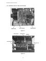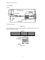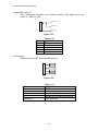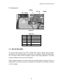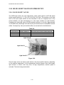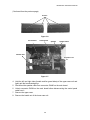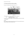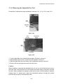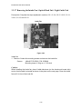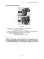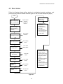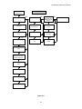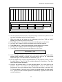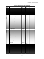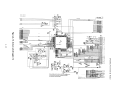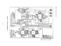
1
Service Manual
ELP-3500
www.electronicsrepair.net
Epson America, Inc.
TM-ELP3500
ELP-3500
Service Manual
ii
INTRODUCTION
This service manual describes hardware information necessary for field service and
troubleshooting of the ELP-3500 Projector. Manual updates will be supplied in service
bulletins.
HOW TO USE THIS SERVICE MANUAL
The manual covers topics required for field maintenance, so you can use it for
diagnosis of failures or repair. Before beginning maintenance work, be sure to read
and observe every safety precautions and all rules. Manual contents are as follows:
Precautions: Operator Safety, Product Safety, Requirements for Servicers
Chapter 1: Product Features (Part Names, Connection, Specifications)
Chapter 2: Theory of Operation (Hardware, Internal Connections, Unit Functions)
Chapter 3: Disassembly and Assembly (Main Unit and Remote Control)
Chapter 4: Troubleshooting (Troubleshooting Flowcharts)
Chapter 5: Functional Tests, Adjustments (Test Programs, Adjustments)
Appendix: Parts List, Exploded Diagrams, Schematic Diagrams
iv
PRECAUTIONS
OPERATOR SAFETY
1. PROTECTION FROM ELECTRIC SHOCK
* Before performing any repair work on the product, be sure to turn off the power
switch and remove the electric power cable from the electrical outlet.
* Whenever it is necessary to turn power on after opening the case or cover (for
example, during the adjustment process) be sure to remove anything you are
wearing that is metal, such as a watch, cuff links, ring, or tie pin, that may touch
metallic parts of the product, creating a danger of electric shock.
2. PROTECTION FROM INJURY
* Be sure not to touch the lamp and its surroundings after power is turned off; they
may be hot. Also, be sure not to touch the light source and its surroundings during
adjustments while power is turned on.
* Use gloves to protect your hands from sharp edges during assembly and
disassembly.
* To protect your eyes from being damaged, do not look into the light source or lens
while the light is on.
3. ACCIDENT PREVENTION
* To prevent the device or its components from falling, perform any operation only
after the device is placed on a flat and stable surface. Be careful not to place tools
or parts on top of the device or at your feet.
* To prevent this product from being used before it is totally reassembled, be sure
not to leave the product out during any repair work, and do not place it in a location
where it can be taken for use by mistake.
* Be sure to use attached power cable to supply power to the product.
PRODUCT SAFETY
1. ELECTROSTATIC DISCHARGE
* Whenever performing repair work on the product, be sure to wear a wrist band and
use an electrostatic mat for grounding. When you replace any electric components
(boards and light bulb), it is recommended that you touch the electrostatic plastic
bag containing the component to a metallic part of the product before taking the
component out of the plastic bag.
2. RESTRICTIONS FOR PARTS REPLACEMENT
* Use only authorized parts or EPSON-supplied parts for replacement of mechanical
components, including the light source lamp, fuse, air filter, and so on.
v
* Use only the power cable and the interface cables supplied with the product.
3. OTHER PRECAUTIONS
* Visually check for damage or dirt on the power connector and cable. If dirty, clean
it, and if bent or damaged, replace the cable in to prevent firing by the flush over
phenomenon.
* When connecting internal connector cables or interface cables, be sure to plug
them into the connector fully, until attached to the connector edge.
* Before removing the FPC cable for the light bulb, be sure to remove the connector
lock in advance. Unlock the connector lock by pulling up both ends of the
connector lock simultaneously with tweezers.
* Whenever removing parts or repairing the product, work in a clean room, free of
dust and dirt, to keep the optical elements away from dirt.
REQUIREMENTS FOR SERVICERS
Authorized servicers should have the following knowledge and skill for maintenance of
the ELP-3500:
* Training in an EPSON-authorized maintenance training program and authorization
as a service engineer.
* Sufficient understanding of the operations and descriptions in this service manual.
* Basic knowledge of electricity (safety operations, circuit diagrams, static electricity,
etc.)
OTHERS
* For questions on ELP-3500 maintenance, including service parts or document
contents, contact the address below. Any technical information about changes will
be released as necessary in service bulletins.
EPSON AMERICA, INC.
20770 Madrona Avenue
Torrance, CA 90503
(310) 782-0770
vi
Contents
Chapter 1 Product Features
1.1 Product Features ........................................................................................ 1-1
1.2 Parts of the Projector ................................................................................. 1-2
1.2.1 Exterior View of the Main Frame ....................................................... 1-2
1.2.2 Interior View of the Main Frame ........................................................ 1-4
1.2.3 Exterior View of the Remote Control ................................................. 1-5
1.2.4 Interior of the Remote Control ........................................................... 1-6
1.3 Connection................................................................................................. 1-7
1.3.1 MS-DOS and Compatibles ................................................................ 1-7
1.3.2 Macintosh.......................................................................................... 1-8
1.4 Main Components ...................................................................................... 1-9
1.5 Specifications............................................................................................. 1-14
1.6 Interface Specifications .............................................................................. 1-15
1.6.1 Mouse Interface Specifications ......................................................... 1-15
1.6.2 Computer Interface Board................................................................. 1-18
1.6.3 Computer Audio Input ....................................................................... 1-18
1.6.4 Video Interface Board ....................................................................... 1-19
1.6.5 I/O Terminal Layout........................................................................... 1-21
Chapter 2 Theory of Operation
2.1 Hardware.................................................................................................... 2-1
2.1.1 Electrical System Connections.......................................................... 2-2
2.1.2 Optical System Connections ............................................................. 2-3
2.2 Power Supply Unit...................................................................................... 2-4
2.3 Main Board................................................................................................. 2-6
2.4 Driver Board ............................................................................................... 2-11
2.5 Interface Board Unit ................................................................................... 2-13
2.6 Control Panel ............................................................................................. 2-15
2.7 Receptor Board .......................................................................................... 2-15
2.8 Speaker Unit .............................................................................................. 2-16
2.9 Light Guide Block ....................................................................................... 2-17
2.10 Light Valve R/G/B to Prism Unit ................................................................ 2-19
2.9.1 R/G/B Light Valves............................................................................ 2-19
2.9.2 Prism Unit.......................................................................................... 2-20
2.11 Projector Lens........................................................................................... 2-20
2.12 Lamp Housing........................................................................................... 2-21
vii
Chapter 3 Disassembly and Assembly
3.1 Disassembly and Assembly Procedures .................................................... 3-1
3.2 Projector Main Unit Disassembly and Assembly ........................................ 3-3
3.2.1 Removing the Lamp Inner Housing................................................... 3-4
3.2.2 Removing the Upper Case Unit and Handle ..................................... 3-5
3.2.3 Removing the Air Filter Frame........................................................... 3-7
3.2.4 Removing the Main Board Block ....................................................... 3-8
3.2.5 Removing the Exhaust Fan Unit........................................................ 3-11
3.2.6 Removing the Safety Switch ............................................................. 3-12
3.2.7 Removing the Control Panel ............................................................. 3-13
3.2.8 Removing the Speaker Units............................................................. 3-14
3.2.9 Removing the Receptor Board Assembly.......................................... 3-15
3.2.10 Removing the Driver Board Assembly............................................. 3-16
3.2.11 Removing the Power Supply Unit.................................................... 3-17
3.2.12 Removing the Interface Unit Assembly ........................................... 3-18
3.2.13 Removing the Lamp Outer Housing Unit......................................... 3-19
3.2.14 Removing the Adjustable Foot Unit................................................. 3-20
3.2.15 Removing the Optical Block ............................................................ 3-21
3.2.16 Removing the Projector Lens Unit (PLU) ........................................ 3-22
3.2.17 Removing the Intake Fan/Optical Head Unit/Light Guide Unit......... 3-23
3.2.18 Removing the Inlet Unit ................................................................... 3-25
3.3 Disassembling and Assembling the Remote Control Unit .......................... 3-26
Chapter 4 Troubleshooting
4.1 Before Starting Troubleshooting Procedures ............................................. 4-1
4.1.1 Tools and Accessories Required for Troubleshooting ................... 4-1
4.1.2 Field Replacement Parts ............................................................... 4-1
4.2 First Action ................................................................................................. 4-2
Chapter 5 Adjustments
5.1 Image Adjustment Program........................................................................ 5-1
5.1.1 When to Use the Image Adjustment Program................................... 5-1
5.1.2 Running the Program ........................................................................ 5-2
Appendix
A.1 Reference Materials (Parts List) ................................................................. A1-A3
A.2 Exploded Diagrams .................................................................................... A4-A5
A.3 Schematic Diagrams................................................................................... A7-A21
viii
1.1 PRODUCT FEATURES
The ELP-3500 Projector is an easy-to-use, portable presentation device with a VGA
resolution that lets you project enhanced color images from personal computers and
video equipment, such as VCRs, video camcorders, and video disc players.
Figure 1-1.
❐ Portable, light-weight, compact
The new power unit, circuit board design, and simple structure minimize the
projector body almost to page-size length and width, and a weight of 14.8 lb (6.7
kg), which is about 2 lb (1 kg) lighter than conventional projectors. An optional
carrying case is useful for transporting the unit.
❐ Bright, clear images
The high-performance zoom lens, new high-brightness lamp, and optical block
let the projector achieve wide-screen image projection (from 21 to 300 inches) at
a projection distance from 4 to 40 feet (1.2 to 12.3 m).
❐ High-resolution, full color (16770 thousand colors)
Three R, G, and B TFT liquid crystal panels containing 307,200 pixels support a
VGA resolution of 640 x 480 dots (approximately 920 thousand pixels). The grid
between pixels in the liquid crystal panel is thinner than in conventional
projectors to provide sharp contrast.
❐ Remote control
The easy-to-use remote control handles numerous functions for presentations.
You can control the main operations with one hand. By attaching the computer
and projector with an optional cable, you can use the remote control as a
computer mouse.
❐ Connectivity with various computers
An advanced capacity for data signal determination enables the ELP-3500 to
connect with various computers, such as IBM PC compatibles (including DOS
compatibles) and Macintosh computers. The projector also can determine
whether the video signal is NTSC, PAL, SECAM.
1-1
EPSON ELP-3500 Service Manual
❐ DDC compliance
The ELP-3500 conforms to DDC 1/2 standards. When you connect this device
to the computer conforming to DDC, the output signals of it are automatically
converted into VGA images and projected.
❐ Simple Maintenance
Maintenance is easy, and the number of adjustments has been minimized.
1.2 PARTS OF THE PROJECTOR
1.2.1 EXTERIOR VIEW OF THE MAIN FRAME
Figure 1-2.
Figure 1-3.
1-2
EPSON ELP-3500 Service Manual
Figure 1-4.
1. VCR Syn-Video
6. Serial Port to Mouse Port
2. VCR Video
(DB9 or PS/2)
3. VCR Audio Left
7. VGA Connection for Video
4. VCR Audio Right
from Computer
5. Output for External Speakers 8. Audio from Computer
Figure 1-5.
Figure 1-6.
1-3
EPSON ELP-3500 Service Manual
1.2.2 INTERIOR VIEW OF THE MAIN FRAME
Main Board
Power Supply
Safety Switch
Figure 1-7.
Driver Board
Control Panel
Speaker
Interface Unit
Projector Lens
Figure 1-8.
1-4
EPSON ELP-3500 Service Manual
1.2.3 EXTERIOR VIEW OF THE REMOTE CONTROL
Figure 1-9.
1-5
EPSON ELP-3500 Service Manual
1.2.4 INTERIOR VIEW OF THE REMOTE CONTROL
Figure 1-10.
Figure 1-11.
1-6
EPSON ELP-3500 Service Manual
1.3 CONNECTION
1.3.1 MS-DOS and Compatibles
Desktop
Figure 1-12.
Notebook
Figure 1-13.
* Attached accessories
1-7
EPSON ELP-3500 Service Manual
1.3.2 Macintosh
Desktop
* Attached accessories
Figure 1-14.
DIP switch settings must match machine type. Refer to the table below for details. (The
default setting is MAC13 mode.)
Table 1-1.
Mode
MAC13” Mode (640 x 480)
MAC16” Mode (832 x 624)
Multi Res.
Switch A ON
1, 2, 5
2, 4, 5
1, 2, 5
Figure 1-15.
1-8
Switch B ON
8
8
3, 4, 8
EPSON ELP-3500 Service Manual
PowerBook
Figure 1-16.
1.4 MAIN COMPONENTS
Main Board
Figure 1-17.
1-9
EPSON ELP-3500 Service Manual
Driver Board
Figure 1-18.
Interface Unit
Figure 1-19.
1-10
EPSON ELP-3500 Service Manual
Power Supply Unit
Power Supply Unit
Figure 1-20.
Light Guide Block
Figure 1-21.
1-11
EPSON ELP-3500 Service Manual
Optical Head Unit
Figure 1-22.
Projector Lens Unit
Figure 1-23.
1-12
EPSON ELP-3500 Service Manual
Lamp Inner Housing
Figure 1-24.
Control Panel
Figure 1-25.
1-13
EPSON ELP-3500 Service Manual
1.5 SPECIFICATIONS
Table 1-2.
OPTICAL FEATURES
Display method
Projection image size
Projection distance
Resolution
Projector lens
Focus adjustment
Zoom adjustment
Light source
Average illuminance
Transparency-type, TFT color liquid crystal display (R/G/B)
21 inches minimum to 300 inches maximum
3.9 to 40.3 feet (1.2 to 12.3 m)
640 x 480 dots; 307,200 pixels x 3
Zoom lens F2.5 - 2.9 (55-77 mm)
Manual
Manual (1:1.4)
100 W
Metal halide lamp, (type no. MSCR150E3H)
Typical: 500 ANSI lumens; minimum: 400 ANSI lumens
AUDIO FEATURES
Input
Output
Input Source 1
Input Source 2
Video audio signal (stereo)
Host computer audio output (stereo)
Built-in speaker (1 W-8 Ω) 4 W - 4 Ω
External speaker
Output control function
Host computer I/O interface
(analog RGB/VGA monitor board/video board)
Audio input interface (stereo)
Video image input interface
S image input interface
Video audio input interface (stereo)
REMOTE CONTROL
Wireless Remote Control
Operation Key
Within 33 feet (10 m) from and within an angle 30 degrees
of the projector's receptor.
Wired control is available using the exclusive cable.
One switch available on the top of projector switch cover.
Input Voltage
Power Consumption
DC Output
100-120 VAC ± 15% / 220-240 VAC ± 15% (50/60 Hz)
Approximately 170 W
12 V; 0.35 A
Dimensions
11.14 (W) x 5.95 (H) x 14.98" (D)
(283 mm x 151 mm x 380 mm)
11.22 (W) x 5.87 (H) x 16.26" (D)
(285 mm x 149 mm x 413 mm)
including foot adjuster and lens.
Approximately 17 lb (7.7 kg)
POWER SUPPLY
MECHANICAL
Weight
ENVIRONMENT
Operation/Storage
Temperature
Operation/Storage Humidity
32º F ~ +104º F / –14º F ~ +140 º F (non condensing)
(0º C ~ +40º C / –10º C ~ 60º C)
20% ~ 80% / 10% ~ 80% (non condensing)
1-14
EPSON ELP-3500 Service Manual
1.6 INTERFACE SPECIFICATIONS
1.6.1 Mouse Interface Specifications
Features
This interface is provided on an optional cable (not on the projector).
❐ Supports a keyboard as well as a mouse
❐ Mini DIN 6-pin connector
❐ I/O data communication is enabled.
PS/2 port pin assignments
6
5
4
3
2
1
Figure 1-26. Mini DIN 6-pin Connector
Pin
1
Signal
Data
2
3
4
5
NC
GND
+5V
Clock
6
NC
Table 1-3. PS/2 Connector Pin Assignments
Functions
I/O data bus. The signal line with the open collector driver is pulled
up to 5 V through a pull-up resistor.
Not connected
Ground
+5 V output
Synchronous clock signal. The signal line with the open collector
driver is pulled up to 5 V through a pull-up resistor.
Not connected
PS/2 port driving procedure
The projector communicates with the peripherals using the IBM PC/AT protocol,
which manipulates the HIGH/LOW level of Data/Clock signals.
1-15
EPSON ELP-3500 Service Manual
Asynchronous Data Bus (ADB) Port
Features
This interface is provided on an optional cable (not on the projector).
❐ 10 kbps serial bus
❐ Supports a keyboard or a mouse.
❐ Mini DIN 4-pin connector
❐ I/O data communication is enabled.
ADB port pin assignments
4
2
3
1
Figure 1-27. Mini DIN 4-pin Connector
Pin
1
2
3
4
Table 1-4. ADB Connector Pin Assignments
Functions
I/O data bus. This is the open collector signal, which is pulled up
to +5 V through the 470 Ω resistor on the main logic board.
POWER ON In Macintosh-type computers this pin is connected to pin 4, so
that using a key on the ADB keyboard activates this signal and
turns on the power. In other models this pin is not connected.
+5 V
+5 V output
GND
Ground
Signal
ADB
Procedure for driving the ADB port
An ADB device communicates with a Mac through a protocol specified by Apple
Computer Inc., which manipulates the HIGH/LOW level of ADB signals.
ADB port current limitations
Through the bus, a +5 V current is supplied to the ADB device. The total current
consumed by the device must not exceed 500 mA. (For example, the current
consumed by an ordinary mouse is approximately 20 mA.)
1-16
EPSON ELP-3500 Service Manual
Mouse Emulation Function
This function converts data transmitted from a remote control into mouse data for a PS/2,
ADB, or serial mouse. The ELP-3500 mouse function does not support a serial mouse. In
the I/F CPU, the function controls the mouse CPU, which controls the multi-mouse port.
Table 1-5. Multi-mouse Connector Mode
Mode
Serial mouse
PS/2
ADB
PC-98
ID 0
0V
0V
5V
5V
ID 1
0V
5V
0V
5V
Note
Not supported in the ELP-3500
The mouse is specified by the cable connected to the multi-mouse connector.
Pin
1
2
3
4
5
6
7
8
9
10
11
12
13
Table 1-6. Multi-mouse Connector Pin Assignments
Signal
Type
Functions
XA/CLK/ADB
Encoder signal / I/O data signal / synchronous
clock signal
XB/DATA
Encoder signal / I/O data signal
YA
Encoder signal
YB
Encoder signal
LEFT/ID0
Left button signal/control signal
RIGHT/ID1
Right button signal/control signal
NC
Common
Disabled
TxD
Serial
Transmit signal
RxD
Serial
Receive signal
DTR
Serial
Projector data terminal ready signal
Serial
PC data set ready signal
DSR
Common
PC power ON signal
GHD
Common
Ground
The current capacity of the multi-mouse port
The supplied current capacity is 50 mA. (For example, the current consumed by
an ordinary mouse is approximately 20-30 mA.)
In sleep mode
In sleep mode the mouse emulation function is also enabled.
1-17
EPSON ELP-3500 Service Manual
1.6.2 Computer Interface Board
Figure 1-28.Computer Video Input
Pin
1
2
3
4
5
6
7
8
Table 1-7. Computer Video Input D-SUB 15 (HD)
Signal
Pin
Signal
Red video
9
+5 V
Green video
10
Synchronous GND
Blue video
11
Monitor (ID bit 0)
Monitor (ID bit 2)
12
SDA
GND
13
Horizontal synchronization
Red video GND
14
Vertical synchronization
Green video GND
15
SCL
Blue video GND
1.6.3 Computer Audio Input
This connector is a stereo mini jack with 2 circuits for detection pins (The detection pins,
which are not required for audio input, provides an audio out terminal.)
1
2
Pin No.
1
2
3
Other pins
3
4
5
6
7
8
9
Figure 1-29. Multi-mouse 13-pin Jack
4
1
8
5
14
9
Figure 1-30.
1-18
Table 1-8.
Signal
GND
Computer audio input L
Computer audio input R
NC
EPSON ELP-3500 Service Manual
Pin
1
2
3
4
5
6
7
Table 1-9.
Pin
Signal
8
LEFT
9
RIGHT
10
ID2
11
ID3
12
+5 V
13
GND
Signal
DATA
CLK
ADB
XA
XB
YA
YB
1.6.4 Video Interface Board
4
3
2
1
S-terminal input
6
5
Figure 1-31. Mini DIN 4-pin with Detection Pin
Pin
1, 2, 6
3
4
5
Table 1-10.
Signal
GND
Y signal input
C signal input
Input detection terminal
CVBS input
RCA, gold-plated connector (only insertion portion), right angle H=15 mm; color:
yellow
2
1
Figure 1-32.
Pin
1
2
Table 1-11.
Signal
GND
Video input
1-19
EPSON ELP-3500 Service Manual
Video audio input L, R
RCA, gold-plated connector (only insertion portion), right angle H=15 mm;
colors: L = white; R = red
Pins 3, 6
Pins 4, 7
Pins 5, 8
Figure 1-33.
Pin
3, 6
4
7
5
8
Table 1-12.
Signal
GND
Audio R return
Audio L return
Audio input L
Audio input R
Audio output
Stereo mini jack with 2 circuits for detection pin
1
2
3
4
5
6
7
8
9
Figure 1-34.
Pin
1, 4
2
3
5
Other pins
Table 1-13.
Signal
GND
Audio output L
Audio output R
Detection of Line-out jack insertion
Not connected
1-20
EPSON ELP-3500 Service Manual
1.6.5 I/O Terminal Layout
The terminals listed below are vertically located in two rows on the rear panel.
Table 1-14.
Left row, from top to bottom
S-Video terminal input (mini DIN 4)
CVBS video input (RCA-yellow)
Video audio input (RCA-left-white)
Video audio input (RCA-right-red)
Audio output (stereo mini)
Right row, from top to bottom Multi-mouse jack
Computer video input (D-SUB 15)
Computer audio input (stereo mini)
Figure 1-35.
1-21
EPSON ELP-3500 Service Manual
1-22
2.1 HARDWARE
The optical and electrical systems are the major areas of projector hardware. The lower
level (below the broken line in the figure) shows the optical system, and the upper level
shows the electrical system.
POWER
SUPPLY UNIT:
Generates DC
voltages
(+5 V +18 V) for
the electric
circuits. Also
generates DC
voltage (+65 V)
for the light
source.
MAIN BOARD:
Generates the R/G/B light
valves’ memory and the
drive signals. Sets initial
operations for interface
circuit and controls
sensors, fans, speakers,
and remote control.
DRIVER BOARD:
Generates the
R/G/B video
signal.
Detects the
brightness and
controls the
temperature.
(overheating
protection).
IINTERFACE
UNIT:
I/O interface
connector
board (PC /
video / audio /
RS-232 /
remote / DC
OUT)
INTAKE FAN *1
R/G/B LIGHT
VALVES
R/G/B
PRISM
composite
LENS UNIT
Focus/Zoom
EXHAUST FAN *2
LAMP
HOUSING:
150 W - 65 V
light source.
LIGHT VALVE
BLOCK: Divides the
light into 3 parts
(R/G/B) for the lens,
filter, and mirror
Note: *1 The intake fan cools the R/G/B
light valves of the LCD panel.
Note: *2 The exhaust fan mainly gives off
heated air from around the light
source.
Figure 2-1.
Description of the Projection Process
1. A video signal is provided in digital or analog form from a computer through the
interface board. (Analog signals are converted into digital signals by the main board.)
2. The digital video signal is then stored in video memory on the main board. Then the
driver board generates signals to drive the R/G/B light valves.
3. The R/G/B light valves are individual panels, independent of each other. They work
to shut off or transmit light from the light valve block.
4. Lights transmitted through the light valves are combined by a prism and projected
through the lens unit.
2-1
EPSON ELP-3500 Service Manual
2.1.1 ELECTRICAL SYSTEM CONNECTIONS
Electrical units are physically connected to the main board, as shown below.
Intake Fan
Power Supply
Unit
Receptor Board
Speaker
CN600
CN502
CN400
CN501
CN504
Main Board
CN505
Control
Panel
CN200
(opposite side)
CN503
CN100
Exhaust Fan
CN101
IB2
IB1
Interface Unit
CN850
CN950
CN900
Driver Board
Light Valve B
Light Valve G
Light Valve R
Figure 2-2.
Table 2-1.
UNIT NAME
EXHAUST FAN
RECEPTOR BOARD
INTAKE FAN
POWER SUPPLY UNIT
MAIN BOARD BOARD
R/G/B LIGHT VALVE
SPEAKER UNIT
LIGHT SOURCE LAMP
DRIVER BOARD
INTERFACE UNIT
FUNCTIONS AND REMARKS
For eliminating heat from light source lamp and power supply unit
Remote control signal detection
Cools the lamp
Generates 65 V from AC IN for light source lamp
Generates +5 V / +12 V / +18 V
Projector function control (CPU, ROM, VRAM, light valve driver, others)
Generates image data (LCD panel)
Audio output
For image projection (metal halide discharge lamp)
A/D converter for analog video signal
Audio signal amplitude, others
External device connection
2-2
EPSON ELP-3500 Service Manual
2.1.2 OPTICAL SYSTEM CONNECTIONS
The optical system consists of 4 blocks (lamp inner/outer housing, light guide unit, optical
head, and projector lens), as shown below.
Lamp Inner/Outer
Housing
Optical Head
Light Guide Unit
Projector Lens
Figure 2-3.
Figure 2-4. Optical Head Assembly
Table 2-2.
UNIT NAME
FUNCTIONS AND REMARKS
LAMP INNER/OUTER HOUSING Includes one metal halide lamp as a light source. Lamp
inner housing and lamp outer housing are mounted.
LIGHT GUIDE UNIT
Disperses light from the light source uniformly using the
A/B lens array.
Disperses the light in three parts (R/G/B).
PROJECTOR LENS
Zoom (*1.4) and focus adjustments
2-3
EPSON ELP-3500 Service Manual
2.2 POWER SUPPLY UNIT
The power supply unit includes a DC regulator, exhaust fan, and interlock switch for the
lamp cover. This unit generates the voltages for the control circuit (+5 V, +12 V, +18 V)
and for the light source lamp (+65 V) from the AC input. Although a functional diagram is
shown below, never disassemble the power supply unit during field maintenance service.
Power Supply Unit
Figure 2-5.
Functional Block Diagram
INTERLOCK SW
FUSE
AC IN
NC
POWER SW
NC
FILTER/
RECTIFIER
REGULATOR
250 V - 6.3 A
MAIN
SAFETY
BOARD
SWITCH
EXHAUST FAN
CN505
(overheating
protection)
LAMP
+6.5 V
+5 V
+18 V
CONNECTIONS TO MAIN BOARD AND DRIVER BOARD
+12 V
Figure 2-6.
* An interlock switch is included for safety purposes. The interlock switch shuts off the supply of AC power if
the lamp cover at the bottom of main chassis is opened.
* The safety switch input signal is designed for protection from overheating. It stops power output to the light
source lamp if the projector detects overheating in the lamp housing area.
2-4
EPSON ELP-3500 Service Manual
Functional Outline
* The interlock switch at the bottom of main chassis shuts off AC power when the lamp
cover is opened. It is normally in the ON position.
* The cable connected to CN505 on the main board is a signal line to indicate the
conditions of two fans (the exhaust fan and intake fan), which are connected to
connectors CN503 and CN502 on the main board. These signals shut off power to the
light source lamp to prevent overheating if either fan stops rotating.
* The filter/rectification circuit reduces noise on the AC line and generates DC voltage
for the regulator.
* The regulator generates various DC voltage levels shown in the table below for the
switching regulator. The regulator detects the voltage output level on the +5 V line and
feeds the information back to the switching circuit to maintain a stable output level,
regardless load variations. Every output voltage level is not subject to adjustment.
Table 2-3.
OUTPUT VOLTAGE
SPECIFICATION
+18 V
+18 V ± 5% (17.1 to 18.9 V)
+12 V
+12 V ± 5% (11.4 to 12.6 V)
+5V
+ 5 V ± 5% ( 4.75 to 5.25 V)
* The intake fan removes heat generated in the power supply unit. Heat expelled by the
intake fan is blown out by the exhaust fan, connected to CN503 on the main board.
2-5
EPSON ELP-3500 Service Manual
Pin Assignments
CN501
Pin 15
CN505
Pin 1 (Red)
Figure 2-7.
Table 2-4.
Pin No.
1
I/O
IN
Signal
Lamp on/off
2-9
—
Ground
7
OUT
+18 V
8
OUT
+12 V (b)
9
OUT
+12 V (a)
10-12
OUT
+5 V
2.3 MAIN BOARD
The driver board consists of the CPU, P-ROM, video memory, digital video processor,
and circuits to control the interface, control panel, fan, speaker, receptor board interface,
etc. The driver board controls everything, except video signal generation. The driver
board is available as a unit for the service parts.
IC304 includes firmware to set initial values and control projector functions. Fuses, for
the protection of the electric circuits, are soldered on the board Their locations are shown
on the next page.
2-6
EPSON ELP-3500 Service Manual
Table 2-5.
Fuses
FU500
FU501
FU502
FU503
FU504
FU505
Specifications
451002 (2 A)
451002 (2 A)
451002 (2 A)
CCP2E20 (0.8 A)
451002 (2 A)
CCP2E20 (0.8 A)
+18 V
+12 VS
+12 VA
+5 VA
+5 VD
+5 VT
IC304
FU500
FU501
FU502
FU503
FU504
FU505
Figure 2-8.
2-7
Purpose
ROM/Interface
Fan/speaker
Interface
A/D converter
All circuits/CPU/interface
Receptor circuits
EPSON ELP-3500 Service Manual
Main Board Circuit Block
Fuse
C
N
5
0
1
Connects to the
power supply
with cable
FU500 451002 (2 A)
+18 V
FU501 451002 (2 A)
+12 VS
FU502 451002 (2 A)
+12 VA
FU503 CCP2E20 (0.8 A)
+5 VA
FU504 451002 (2 A)
+5 VD
+5 VT
FU505 CCP2E20 (0.8 A)
POWER ON
CN505
IC600 Control
panel power
On/Off control
OSC 16M
SRAM
MAD
IC301
CPU
LED control
Thermos
signal
Flash ROM
PAJ system
PC control
control
Lamp control
controller
Read / write
signals
Intake
fan
C
N
5
0
2
Fan control
Speaker
Line buffer
R
S
0
G B
S S
0 0
7
7
to the
control panel
CN
Connects to
600
receptor board
C
N
Connects to
1
the interface
0
board
0
Display signal
generator
7
C
IC201 Digital-
N
Video processor
RT 0 ~ 7 / GT 0 ~ 7 / BT 0 ~ 7
Display signal / data clock
C
N
5
0
3
C
N
4
0
0
R/G/B IN
GIN
HS/VS
circuit
PLL
Exhaust
fan
M1 11
(Mouse)
IC102
ADC
t
Connects
OSC
8 MHz
SCL
SBA
Memory
C
N
5
0
4
2
0
Connects to
the driver
board
0
Digital croma
A/D
converter
Speaker
AMP
S-Video/Video in
C
Audio R/L in
N
Connects
Audio out
1
to the interface
0
unit (IB1)
1
Figure 2-9.
2-8
EPSON ELP-3500 Service Manual
Functional Outline
* When power is turned on, the driver board activates the reset signal, which is
controlled by IC601, and the CPU reads the program from flash ROM and writes it into
RAM (IC303). Then the CPU sets the functions based on the program and projects
the initial image.
* The digital video interface (IC201) from the video board generates timing to project the
image data received or executes data bit conversion (A/D) to write the received
analog image data to SRAM.
* The memory controller (IC302) performs read/write operations, saving data to SRAM.
Video signals (analog/digital), provided through the interface board, are immediately
stored in video RAM.
* Data stored in SRAM is converted to analog signals by D/A converter. The output is
divided into 8 bits for each R/G/B light valve by the amplitude and lamp circuits.
* Digital R/G/B input signals are synchronized as image data, and the control timing is
stored in a three-state buffer before being output to the driver board.
* The analog R/G/B signal is amplified by the amplitude circuit and converted into
individual data signals of 7 bits each by A/D converter circuit before being output to
the driver board.
* Analog R/G/B output signals are transmitted in different ways for analog input and
digital input.
Analog R/G/B
Video amplitude is output via video buffer.
Digital R/G/B
The digital image signals (R 0 ~ 7 / G 0 ~ 7 / B 0 ~ 7) output from the driver board
are converted into analog signals by the chroma circuit and the D/A converter
before being output through the video buffer.
* Audio input volume is controlled (Loud/Quiet/Mute) by the audio control circuit and
amplified by the audio amplitude circuit before being output to the speaker unit
(Right/Left) through the driver board.
* The audio input signal is transferred to the audio output interface via the audio control
circuit.
2-9
EPSON ELP-3500 Service Manual
* The projector has a timer circuit that controls the operating time of the light source
valve. Its operation is described below.
Table 2-6.
Light Source State
Lamp Monitor State
Typically, the light from the projector lamp starts to dim after about 4000 hours of use.
This indicates that it is time to replace the lamp. You can check the lamp life on the
Setting Screen.
When the light source valve runs out
The lamp monitor lights red.
before its life.
If you observe the conditions above, replace the light source valve and reset the timer as
follows:
While holding down the TRACKING+ and SYNC+ buttons, press and hold down the
POWER button until the three status lights (USER 1, 2, 3) start flashing orange
simultaneously (for approximately 3 seconds).
2-10
EPSON ELP-3500 Service Manual
2.4 DRIVER BOARD
The driver board has a circuit for converting the signals from the main board into six
analog signal states and controlling the brightness and detecting the temperature. The
board can be replaced as a whole unit for maintenance service. The fuses on the board
are shown below.
Table 2-7.
Fuse Part Number
Usage
F600 CCP2E20
+18 V (600 mA) Video AMP
F601 CCP2E20
+12 V (600 mA) DAC/Light Valve Driver
F602 CCP2E13
+5 V (520 mA) Control Circuits
F600
F601 F602
Figure 2-10.
Functional Outline
Signals RT 0~7, GT 0~7, and BT 0~7, output from the main board, are converted into
analog signals by the digital to analog converter (DAC: IC601) before being output to the
driver circuit for the light valves.
Timing signals (for the monitor) output from the main board are converted into the signals
for the light valves (LCDs) by IC800 before outputting them. The sub-brightness circuit
modifies the output level of the R/G/B analog signals while controlling the lamp circuit for
the analog display signals.
The temperature detection circuit protects the circuit section from overheating. If the
temperature in the section rises more than a certain number of degrees, the circuit sends
an interrupt to the CPU on the main board.
2-11
EPSON ELP-3500 Service Manual
Circuit Block Diagram of the Video Board
Fuses
Power
supply
C
N
6
0
0
F600 CCP2E20 (600 mA)
Regulator
+18 V
F601 CCP2E20 (600 mA)
+12 V
F602 CCP2E13 (520 mA)
+5 V
Regulator
Temperature
detection
RT 0 ~ 7
IC600
GT 0 ~ 7
IC601
DAC
line buffer
5 VDA
BT 0 ~ 7
Analog R/G/B
Data clock
H start
Data clock
Lamp 2
Display control signal
Video AMP
SCL/SDA
8 ch
DAC
IC800
display timing
generator
Shift clock
level shifter
Sub
brightness
circuit
Output lamp
8 ch
+15 V
I/O
Connecst to
the main
board CN200
SCK
1~6
LCCOM
RAD
control
(J1/J2)
RAD
(J1/J2)
LCCOM
RAD (J1/J2)
R/G/B
DXIN
CLXIN
ROT
Driver
B 1/2
G 1/2
R 1/2
Output divider
Output divider
Output divider
(Analog)
(Analog)
(Analog)
R1 ~ R6
G1 ~ 6
B1 ~ 6
R 1/2
G 1/2
B 1/2
Light Valve R Driver
(CN850)
Light Valve G Driver
(CN900)
Figure 2-11.
2-12
Light Valve B Driver
(CN950)
EPSON ELP-3500 Service Manual
2.5 INTERFACE BOARD UNIT
This unit consists of two boards (IB1 and IB2) with interfaces that can be connected to
external devices (the host computer, external speaker, and video device). The unit
involves the input/output interface connector and the noise filter circuit.
Figure 2-12.
2-13
EPSON ELP-3500 Service Manual
Interface board (IB2)
Mouse/
J100
Current limiter
Com
connector
(100 Ω)
Computer
J101
In
connector
R/G/B
Noise filter
(diode circuit)
Noise filter
(diode circuit)
C
N
1
0
0
Connects to
CN100 (IF2)
on main board
H/V/SCL control
Audio
J102
R/L
Noise filter
In
Figure 2-13.
Interface board (IB1)
S-Video
J100
Video In
J101
C
N
1
0
0
Noise filter
R/G/B
Noise filter
Audio L
Audio R
Audio
J102
R/L
Noise filter
Out
Figure 2-14.
2-14
Connects to
CN101 (IF1)
on main board
EPSON ELP-3500 Service Manual
2.6 CONTROL PANEL
The board on this panel contains eight buttons and six LEDs. It is connected to CN504
on the main board.
Figure 2-15.
2.7 RECEPTOR BOARD
A detector mounted on the receptor board senses the infrared signals from the remote
control. The receptor board is attached to the power supply unit and placed in the front of
the unit. Control of any signals received by the receptor board is transferred to the CPU
as interrupt signals.
Figure 2-16.
2-15
EPSON ELP-3500 Service Manual
2.8 SPEAKER UNIT
Inside the upper case is a speaker. Audio signals from the amplitude circuit on the video
board are output to this speaker. Also, audio signals are available from externally
connected speakers. In this case, balance between internal and external speakers is
adjustable using the fade function.
Figure 2-17.
2-16
EPSON ELP-3500 Service Manual
2.9 LIGHT GUIDE BLOCK
The light valve block eliminates ultraviolet rays harmful to the light valves and makes the
light intensity from the light source lamp uniform before dividing it into 3 light outputs
(R/G/B). Lenses and mirrors built in the block disperse the light. The drawings below
show the appearance and an internal block diagram of the light valve block.
Figure 2-18.
PBS
Multi-lens B
Multi-lens A
GCM
Lens Adjustment Unit
Condenser Lens F
CDM
Condenser Lens E
RGB Condenser Lens
RGB Polarization Unit
Figure 2-19.
2-17
EPSON ELP-3500 Service Manual
A/B Multi-lens
Dispersion of light from the light source lamp through the A/B multi-lens makes
brightness roughly uniform. A UV filter coats the surface of the multi-lens array to
eliminate ultraviolet rays.
PBS (Polarizing Beam Splitter)
Light dispersed through the A/B multi-lens is further dispersed through the PBS to
make the light intensity uniform.
Lens Adjustment Unit
Adjusts the distortion of light applied through the A/B multi-lens, the polarizing beam
splitter, and the CDM (see definition below).
CDM
The CDM is a light filter that looks red in visual light. The CDM (A) filter transmits only
red light and reflects blue and green lights from the light source.
GDM
The GDM is a light filter that looks blue in visual light. The GDM filter transmits only
blue light from the light source. The light input to the GDM is only blue and green light
reflected by the CDM, as described above, and green light is reflected by the GDM
and provided to the G condenser lens.
D/E Condenser Lens
The D/E condenser lens collects the light dispersed by the GDM to prevent reduction
and provide light to the mirror at the next stage.
R/G/B Condenser Lens
Collects the light divided into R, G, and B.
R/G/B Polarization Unit
Controls the color of lights dispersed into red/blue/green by the CDM and GDM. Films
in the colors shown below are placed on each sheet of the polarization unit.
Table 2-8.
NAME
COLOR OF FILM
POLARIZATION R
GRAY
POLARIZATION G
BLUE
POLARIZATION B
RED
2-18
EPSON ELP-3500 Service Manual
2.10 R/G/B LIGHT VALVES TO PRISM UNIT
2.10.1 R/G/B LIGHT VALVES
The R/G/B light valves are each high-density, liquid crystal panels of 307,200 pixels
(liquid crystal shutters) of 1.1” (W) x 0.8” (H) (26.9 x 20.2 mm). The condition of the twist
level in the liquid crystal shutter can be controlled in units of 8 degrees from a fully
closed condition (no light transmission) to a fully open condition (no light blocked).
Combining the three light valves (R/G/B) enables projection in full color (approximately
16,700,000 colors). Each light valve has its own part number and is incompatible with the
others. Consequently, their part numbers differ, as summarized in the table below.
Table 2-9.
NAME
LIGHT VALVE G
PART NO.
1021660 (1028151) *1
REMARKS
Light valve G does not have a position adjust plate.
LIGHT VALVE B
1022063 (1027966) *1
Light valve B has a blue label on the FPC cable.
LIGHT VALVE R
1021674 (1027964) *1
Light valve R has a red label on the FPC cable.
Light Valve B
Light Valve G
Light Valve R
Figure 2-20.
Since the light valves are liquid crystal shutters, they have specific features, depending
on the ambient temperature. At low temperatures, reaction speed is fast. After-image,
light contrast, or thinner color may occur. At high temperatures, reaction speed is
activated. The whole image seems dark.
2-19
EPSON ELP-3500 Service Manual
2.10.2 PRISM UNIT
The prism unit creates the three lights, which are transmitted through the light valve.
Figure 2-21.
2.11 PROJECTOR LENS
The projector lens unit has a zoom function (*1.4) and focus adjustment function.
Zoom Function
Focus Adjustment
Figure 2-22.
2-20
EPSON ELP-3500 Service Manual
2.12 LAMP HOUSING
The lamp housing consists of the light source valve and connector for the power supply
unit.
Figure 2-23.
* The life expectancy of the light source valve is 4000 hours. When operating time
exceeds 4000 hours, the lamp indicator on the control panel blinks automatically. If
you encounter this condition, replace the light source valve as soon as possible.
* The safety switch on the lamp outer housing, beside the lamp housing, detects
overheating. If the temperature exceeds the safety zone because of abnormal lamp
conditions, this switch shuts down the power.
Figure 2-24.
2-21
EPSON ELP-3500 Service Manual
Table 2-10.
Warning Light
Temp
Lamp
Temp and Lamp
Color
Red
Red
Flashing Red
Status
Projector is hot.
Lamp needs to be replaced.
Projector problem. Try turning off and back on
first. Then see Chapter 4.
2-22
3.1 DISASSEMBLY AND ASSEMBLY PROCEDURES
This section explains how to disassemble the ELP-3500. The assembly procedure is the
exact reverse of the disassembly procedure.
Preparation
1. Remove any rings, wrist watch, cuff links, or other metal accessories likely to come
into contact with the equipment.
2. Wear gloves.
3. Wear a wrist band and ground it. Place a ground mat under the unit.
4. Turn off the main unit and the host computer.
5. Unplug the power cord from the main unit and service outlet.
6. Disconnect the interface cable from the main unit.
7. Clean the air filter, interface, and case cover with a vacuum cleaner.
Required Tools and Accessories
Prepare the tools and accessories listed in the table below.
Table 3-1. Required Tools
Name
Phillips screwdriver 2
Flat blade (–)
screwdriver
Tweezers
Quantity
1
1
Supplier
Commercial
Commercial
Use
Dissasembly of the case and interior
Removal of power connnector for light
1
Commercial
Phillips screwdriver 1
Open wrench
(8 mm)
Set wrench
(1.27 mm)
Brush
Vacuum cleaner
Paper wiper
Air blower
Glove
Wrist band, ground
map
1
1
Commercial
Commercial
To unlock the FPC connector on the driver
board
Removal of the optical unit
Removal of the foot adjuster
1
EPSON
Focus alignment (optical unit)
Commercial
Commercial
Commercial
Commercial
Commercial
Commercial
To brush off the dust around fan
To clean the optical unit and filter
To clean the projector lens
To clean the optical unit
To avoid cuts
To avoid electrostatic effects
1
1
Some
1
1
1
3-1
EPSON ELP-3500 Service Manual
Precautions
Read the precautions given in individual assembly and disassembly procedures carefully
before starting the procedure. General precautions are given below.
When you disassemble the projector main unit, be careful of dust sticking to internal fans
and air filters because it can migrate and contaminate the optical unit, which is the heart
of the display mechanism, causing display quality to deteriorate. The optical unit is also
highly sensitive to static electricity.
The speaker unit contains a permanent magnet. Keep it away from electromagnetic
media such as diskettes and magnetic cards.
Handle the projector lens and light guide units with care as they are highly susceptible to
vibration and shock.
Do not try to disassemble any part (for example, the power supply unit) not covered in
this manual.
Operations that Require Adjustments and Checks
When you perform one of the removal or replacement operations in the table below, you
need to perform the checks and adjustments explained in Chapters 5. Perform
necessary adjustments and checks before reinstalling the upper case unit.
Table 3-2.
Operation
Driver board replacement
Flash ROM replacement
Optical unit replacement
Adjustment and check item
Check the 16 grayscale levels
Flicker/Ghost/Sub-contrast adjustments
Check and adjust focus alignment
Flicker/Ghost/Sub-contrast adjustments
3-2
EPSON ELP-3500 Service Manual
3.2 Projector Main Unit Disassembly and Assembly
The flowchart for disassembling the projector main unit is shown below. You can
reassemble dismantled projector parts by reversing the order of disassembly. Therefore,
unless specifically specified, this manual contains no assembly procedures. Detailed
descriptions of disassembly procedures are given in sections 3.2.1 through 3.2.18.
START
Upper case
(3.2.2)
Air filter frame
(3.2.3)
Main board
(3.2.4)
Handle
(3.2.1)
Exhaust fan
(3.2.5)
Safety switch
(3.2.6)
Driver board
(3.2.10)
Power supply
unit (3.2.11)
Interface unit
(3.2.12)
Lamp outer
housing (3.2.13)
Lamp inner
housing (3.2.1)
Adjustable feet
(3.2.14)
Projector lens
unit (3.2.16)
Optical block
(3.2.15)
Intake fan / optical head unit
/ light guide unit (3.2.17)
Inlet unit
(3.2.18)
Figure 3-1.
3-3
Control panel
(3.2.7)
Speaker
(3.2.8)
Receptor board
(3.2.9)
EPSON ELP-3500 Service Manual
3.2.1 Removing the Lamp Inner Housing
Screws
Lamp Cover
Figure 3-2.
Screws
Handle
Lamp Inner Housing
Figure 3-3.
1. Remove the lamp cover mounting screws from the main unit bottom plate and
remove the lamp cover.
Screws:
M4x7.5 F/Ni: P/N 1021771
Mounting torque: 4.5 kg cm = 3.9 lb inch
2. Remove 2 lamp mounting screws from the inner housing.
Screws:
M4x7.5 F/Ni: P/N 1021771
Mounting torque: 4.5 kg cm = 3.9 lb inch
3. Pull up the handle on the lamp inner housing and remove the lamp unit.
Warning:
1. The lamp unit is very hot immediately after use and may burn you if handled
carelessly. Before removing the lamp unit, make sure the temperature of the lamp
inner housing unit has cooled down.
2. When installing the lamp unit, take care not to touch the lamp's reflector with your
hands (to prevent the reflector from being contaminated).
3-4
EPSON ELP-3500 Service Manual
3.2.2 Removing the Upper Case Unit and Handle
Handle Holder Cover
Figure 3-4.
Screws
Figure 3-5.
1. Pull the handle up. Insert the spring hook into either hole in the handle holder cover
and, while pressing the spring hook toward the hole on the opposite side, pull it up to
remove the handle. Bend the center of the handle holder cover up, forming an arch.
2. Remove 2 screws beneath the handle holder cover.
Screws:
+M3x12 F/Zn P-Tight: P/N 1021823
Mounting torque: 6.0 kg cm = 5.2 lb inch
3. Remove 4 case unit fixing screws on both sides.
Screws:
+M4x8 F/ZB Bind: P/N 1033026
Mounting torque: 6.0 kg cm = 5.2 lb inch
Caution:
The handle holder cover has claws on both ends. They may be damaged if you insert the
spring into a hook's hole and simply pulling it up.
(Continued on the next page)
3-5
EPSON ELP-3500 Service Manual
(Continued from the previous page)
Screws
Figure 3-6.
Driver Board
Control Panel
Speaker
Speaker Cable
Interface Unit
Projector Lens
Figure 3-7.
4. Hold the left and right sides (handle and fan guard sides) of the upper case unit and
lightly pull the handle straight up.
5. Disconnect the speaker cable from connector CN400 on the main board
6. Unlock connector CN504 on the main board before disconnecting the control panel
cable from it.
7. Remove the upper case.
8. Remove the handle out of the lower case unit.
3-6
EPSON ELP-3500 Service Manual
3.2.3 Removing the Air Filter Frame
Air Filter Frame
Figure 3-8.
1. Push the tab on the air filter frame. Then lift it up.
3-7
Tab
EPSON ELP-3500 Service Manual
3.2.4 Removing the Main Board Block
Prerequisite: Complete the steps explained in Section 3.2.2.
8
4
9
6
7
5
2
3
1
Figure 3-9.
1. Remove 7 wire cables and 2 FPC cables from the main board block. The cables
are summarized in the table below.
Number
Connector
1
2
3
4
5
6
7
8
CN100
CN101
CN400
CN501
CN502
CN503
CN504
CN505
CN600
9
Function and Remarks
Interface unit
Interface unit
Speaker unit *
Power supply unit
Intake fan
Exhaust fan
Control panel *
Power supply unit
Receptor board
* Removed in Section 3.2.1
Caution:
Before disconnecting the FPC cable from connectors CN100 and CN101 (1 and 2),
gently pull each connector straight up to unlock it.
3-8
EPSON ELP-3500 Service Manual
(Continued from previous page)
Screw
FG Strap
Figure 3-10.
Screws
Screws
Remove
Bracket
Screws
Figure 3-11.
2. Remove the screw mounting the FG strap on the power supply unit.
Screw:
+M3x6 F/Ni Sems P/N 1033025
Mounting torque: 6.0 kg cm = 5.2 lb inch
3-9
EPSON ELP-3500 Service Manual
3. Remove 7 mounting screws from the main board block (one of the screws mounts
the FG strap also).
6 Screws: +M3x6 F/Ni: Sems P/N 1033122
Mounting torque: 6.0 kg cm = 5.2 lb inch
1 Screw:
+M3x12 F/Zn: Bind P Tight P/N 1021823
Mounting torque: 6.0 kg cm = 5.2 lb inch
4. Grasp the main board block on the left side (the portion indicated by the arrow in the
photo ) and disconnect the connector from the interface board assembly.
Caution
To avoid malfunctions caused by wire breaking or solder flaking, never apply any
mechanical stress to the board.
3-10
EPSON ELP-3500 Service Manual
3.2.5 Removing the Exhaust Fan Unit
Prerequisite: Complete the steps explained in Section 3.2.1.
Exhaust Fan
Fan Holding
Plate
Screw
Figure 3-12.
Screws
Figure 3-13.
1. Disconnect the cable connected to CN503.
2. Remove 4 screws from the fan holding plate to detach the fan and holding plate.
Screws: +M3x8 F/Zn: P Tight P/N 1021824
Mounting torque: 6.0 kg cm = 5.2 lb inch
Screws: +M3x6 F/Ni: P/N 1033122. Mounting torque: 6.0 kg cm = 5.2 lb inch
3. Remove 2 screws mounting the exhaust fan and separate the fan and holding plate.
Screws: +M4x10 F/Zn Bind: P/N 1022793
Mounting torque: 6.0 kg cm = 5.2 lb inch
Caution:
1. When installing the exhaust fan, use care with its orientation. Installing the fan in the
reverse orientation may result in a device failure or extended cooling time because of
overheating. Make sure the label on the fan faces out.
2. The exhaust fan unit and its peripherals are susceptible to dust and dirt. When
installing the exhaust fan unit, check it for dirt and clean it if necessary.
3-11
EPSON ELP-3500 Service Manual
3.2.6 Removing the Safety Switch
Prerequisite: Complete the steps explained in Section 3.2.1.
Fast-on Tabs
Safety Switch
Screws
Figure 3-14.
1. Disconnect the Fast-on tab terminals for the 2 cables connected to the safety switch.
2. Remove 2 mounting screws from the safety switch and detach the safety switch.
Screws:
+M3x8 F/Zn: P-Tight P/N 1021824
Mounting torque: 6.0 kg cm = 5.2 lb inch
Caution:
When removing the Fast-on terminals, do not apply excessive force to the terminals on
the safety switch in the horizontal or vertical direction.
* The polarity of the cables (blue/white) is not significant; connect them to any terminals
on the safety switch.
3-12
EPSON ELP-3500 Service Manual
3.2.7 Removing the Control Panel
Prerequisite: Complete the steps explained in Section 3.2.1.
Tabs
Tabs
Figure 3-15.
1. Pull down the tabs from inside. Then remove the control panel on the upper case.
Figure 3-16.
3-13
EPSON ELP-3500 Service Manual
3.2.8 Removing the Speaker Units
Prerequisite: Complete the steps explained in Section 3.2.1.
Screws
Screw
Figure 3-17.
1. Remove 3 screws mounting the speaker unit and remove the speaker along with the
bracket.
Screws:
+M3x8 F/Zn: P-Tight P/N 1021824
Mounting torque: 6.0 kg cm = 5.2 lb inch
Caution:
1. The speaker unit contains a permanent magnet. Keep it away from electromagnetic
media such as diskettes and magnetic cards.
2. When mounting a speaker, align the 3 screw holes in the speaker with those in the
frame; then tighten the screws with same tightening torque.
3-14
EPSON ELP-3500 Service Manual
3.2.9 Removing the Receptor Board Assembly
Prerequisite: Complete the steps explained in Section 3.2.1.
Screw
Receptor
Board
Power Supply Unit
Figure 3-18.
1. Remove the screw mounting the receptor to the power supply unit.
Screw:
+M3x6 F/Ni: P/N 1033122
Mounting torque: 4.5 kg cm = 3.9 lb inch
2. Disconnect the cable from CN600 on the driver board block, and remove the receptor
board assembly.
Caution:
When installing the receptor board assembly, align the hole in the board with the boss on
the power supply unit before tightening the screw.
3-15
EPSON ELP-3500 Service Manual
3.2.10 Removing the Driver Board Assembly
Prerequisite: Complete the steps explained in sections 3.2.1 and 3.2.4.
Stud Screws
CN900
CN850
CN950
Ground
Plate
Screws
Figure 3-19.
1. (Although the illustration above shows 2 GND plate mounting screws and the GND
plate, those parts are actually removed in step 2 of Section 3.2.4, on page 3-9.)
2. Unlock the connector locks for CN850, CN900, and CN950 to disconnect the light bulb
FPC cable.
3. Remove 4 driver board assembly mounting hex. stud screws.
4. Hold both edges of the driver board assembly and pull it straight up.
3-16
EPSON ELP-3500 Service Manual
3.2.11 Removing the Power Supply Unit
Prerequisite: Complete the steps explained in sections 3.2.1 and 3.2.4.
Screws
Power Supply Cables
Figure 3-20.
1. Remove 2 lamp power supply cables connected with the lamp’s inner housing unit
screws.
Screws:
+M3x8 F/Zn: P-Tight P/N 1021824
Mounting torque: 6.0 kg cm = 5.2 lb inch
2. Disconnect the cables (blue/white) from the safety switch.
3. Remove 4 mounting screws from the power supply unit.
Screws:
+M3x8 F/Zn: P/N 1021824
Mounting torque: 6.0 kg cm = 5.2 lb inch
4. Remove the ground cable mounting screw.
Screw:
+M4x6 F/Ni: P/N 1033025
Mounting torque: 6.0 kg cm = 5.2 lb inch
5. Pull the power supply unit straight up with the inlet cover.
Caution:
When removing the power supply unit, take care not to bend or damage the bosses on
the lower case unit. When installing the power supply unit, align the power supply unit by
positioning holes with these bosses. The intake fan and its peripheral parts in the power
supply unit are susceptible to dust and dirt. When installing the power supply unit, check
the fan's cleanness and clean it if necessary.
3-17
EPSON ELP-3500 Service Manual
3.2.12 Removing the Interface Unit Assembly
Prerequisite: Complete the steps explained in sections 3.2.1 and 3.2.4.
Ground Cable Screw
Screws
Figure 3-21.
1. Remove the GND cable mounting screw.
Screw:
+M3x6 F/Ni: P/N 1033122
Mounting torque: 6.0 kg cm = 5.2 lb inch
2. Remove 2 interface unit assembly mounting screws.
Screws:
+M3x8 F/Zn P-Tight: P/N1021824
Mounting torque: 6.0 kg cm = 5.2 lb inch
3. Remove the fan holding plate mounting screw.
Screw:
+M3x6 F/Ni : P/N1033122
Mounting torque: 6.0 kg cm = 5.2 lb inch
4. Slide the interface unit slightly inward so it does not contact the frame, before
removing it.
Caution:
When installing the interface board assembly, align the 2 positioning holes (beside the
screw holes) in the board with the bosses on the bracket before tightening the screws.
3-18
EPSON ELP-3500 Service Manual
3.2.13 Removing the Lamp Outer Housing Unit
Prerequisite: Complete the steps explained in sections 3.2.1 and 3.2.6.
Screws
Lamp Air Guide
Figure 3-22.
Screw
Figure 3-23.
1. Remove 2 lamp air guide mounting screws to detach the lamp air guide.
Screws:
+M3x8 F/Zn P-Tight: P/N 1021824
Mounting torque: 6.0 kg cm = 5.2 lb inch
2. Remove the lamp outer housing unit mounting screws and remove the lamp outer
housing unit.
Screws:
+M3x8 F/Zn: P/N 1021824
Mounting torque: 6.0 kg cm = 5.2 lb inch
Caution:
The interior of the lamp outer housing is susceptible to dust, if necessary, clean it before
reinstalling it. The lamp outer housing remains hot for a while after power is turned off.
Remove the housing after it cools down completely.
3-19
EPSON ELP-3500 Service Manual
3.2.14 Removing the Adjustable Foot Unit
Prerequisite: Complete the steps explained in sections 3.2.1, 3.2.4, 3.2.10, and 3.2.11.
Foot
Lever
Adjustable
Foot
Figure 3-24.
Compression
Spring
Foot
Lever Pin
Foot
Axis
Foot Lever
Figure 3-25.
1. Turn the adjustable foot counterclockwise about 40 times to remove it.
2. While pressing the foot lever, pull the foot axis upward to remove it.
3. Slide the upper side (foot lever side) of the compression spring to remove it.
4. Remove the foot lever pin then remove the foot lever
Caution:
When installing or removing the adjustable foot unit, do not fold or peel the foot seal on
the lower case. Insert the foot lever, then replace the counter spring, and finally insert the
foot axis. When installation is complete, press the foot lever to check whether it makes a
strange noise. If it makes noise, adjust the compression spring to change the contact
point with the foot lever to eliminate the noise.
3-20
EPSON ELP-3500 Service Manual
3.2.15 Removing the Optical Block
Prerequisite: Complete the steps explained in sections 3.2.1, 3.2.4, 3.2.5, 3.2.10, 3.2.11,
3.2.12, and 3.2.13.
Screws
Screws
Figure 3-26.
1. Remove 4 optical block mounting screws.
Screws:
+Mx14 F/Zn Bind P Tight: P/N 1021825
Mounting torque: 6.0 kg cm = 5.2 lb inch
2. Pull the optical block straight up from the lower case.
Figure 3-27.
3-21
EPSON ELP-3500 Service Manual
3.2.16 Removing the Projector Lens Unit (PLU)
Prerequisite: Complete the steps explained in sections 3.2.1, 3.2.4, 3.2.5, 3.2.10, 3.2.11,
3.2.12, 3.2.13, and 3.2.15.
Screws
Screw
Screw
Figure 3-28.
1. Remove 4 screws securing the projector lens unit (PLU) and remove the projector lens
unit.
Screws:
+M4x6 F/Zn: P/N 1004532
Mounting torque: 6.0 kg cm = 5.2 lb inch
Caution:
1. When installing the projector lens unit, align the 2 bosses on the frame with the
positioning holes before tightening the screws. Tighten the screws with a torque of 6.0
kg. Do not make the screws too tight (too great a mounting torque may damage the
projector lens unit).
2. Take care not to touch the lens surface or prism of the projector lens unit with your
hands (to prevent their surface from being contaminated).
3-22
EPSON ELP-3500 Service Manual
3.2.17 Removing the Intake Fan / Optical Head Unit / Light Guide Unit
Prerequisite: Complete the steps explained in sections 3.2.1, 3.2.4, 3.2.5, 3.2.10, 3.2.11,
3.2.12, 3.2.13, and 3.2.15.
Intake Fan
Screws
Figure 3-29.
Intake fan
1. Remove 2 intake fan mounting screws and remove the intake fan.
Screws:
+M4x20 F/Zn S2W1: P/N 1032848
Mounting torque: 6.0 kg cm = 5.2 lb inch
Caution:
When installing the intake fan, place it label-side down (on the aluminum die-cast side)
and so that its cable is oriented as shown in the photo on the next page. Clean the intake
fan until it is free of dust and dirt.
3-23
EPSON ELP-3500 Service Manual
Optical Head Unit/Light Guide Unit
Screws
Figure 3-30.
1. Remove the mounting screw on the bottom of the optical head unit.
Screw:
+M4x8 F/Zn: P/N 1024565
Mounting torque: 6.0 kg cm = 5.2 lb inch
1. Remove 2 mounting screws on the top of the optical head unit before pulling the light
guide unit up straight and separating it from the optical head unit.
Screws:
+M4x10 F/Zn: P/N 1022793
Mounting torque: 6.0 kg cm = 5.2 lb inch
Caution:
Do not touch the 3 light valve screens on the light guide unit with your hands, and do not
bend the FPC cable. When installing the light guide unit on the optical head unit, align
the 2 bosses (beside the screws for the light guide unit) to the holes in the optical head
unit before tightening the screws. The optical head mounting screw (M4x8) on the bottom
of the unit is different in length from the mounting screw (M4x10) on the top. Check
screw size before mounting them.
3-24
EPSON ELP-3500 Service Manual
3.2.18 Removing the Inlet Unit
Prerequisite: Complete the step explained in sections 3.2.1, 3.2.4, 3.2.5, 3.2.10, 3.2.11,
3.2.12, 3.2.13, and 3.2.15.
Screw
Figure 3-31.
1. Remove the inlet unit mounting screw.
Screw:
+M3x8 F/Zn P-Tight: P/N 1021824
Mounting torque: 6.0 kg cm = 5.2 lb inch
2. Remove the cable wire from 4 clamps.
3. Pull up the board section of the inlet unit to remove the unit.
Clamps
Figure 3-32.
3-25
EPSON ELP-3500 Service Manual
3.3 Disassembling and Assembling the Remote Control Unit
The whole remote control unit is handled as a service part; its components are not
designated as service parts. So, disassemble the remote control unit only to clean its
trackball or buttons.
Figure 3-33.
Figure 3-34.
Figure 3-35.
1. Remove the battery cover from the rear panel, and remove 2 battery cells.
2. Remove 1 screw behind the battery holder.
3. While pushing up the rear cover, push the 4 hooks for the battery block in to unlock
the cover.
4. Bend the rear cover right and left to unlock the 6 hooks before removing the cover.
5. Remove 4 fixing screws to detach the board.
3-26
4.1 Before Starting Troubleshooting Procedures
1. Before you replace a unit or block, double-check that it is actually defective. (For
example, check that cables are connected properly.)
2. Find the points you want to check by examining the flowchart, and check those items
during the troubleshooting procedure.
3. See instructions in Chapter 3, "Disassembly and Assembly," to replace projector units.
4. Before making a functional check, check connections.
5. After replacing any unit listed below, make adjustments explained in Chapter 5.
Table 4-1.
No.
1 Optical Unit
2
Name
Driver board
3
Main board
4
ROM (IC304) on the main board
6. After troubleshooting, make functional checks using the image adjustment program
explained in Chapter 5, and verify that the problem has been solved.
4.1.1 Tools and Accessories Required for Troubleshooting
Tools and accessories required for projector troubleshooting (including fault isolation) are
listed below.
Table 4-2.
Name
Projector screen
Quantity
1
To project images
Use / Remarks
Ruler (10 feet, 3 m)
1
To measure the projection distance
Small-size mirror
1
Host computer
1
To check the optical axis (digital mirror or round mirror with a
diameter of approx. 2 cm)
To supply test patterns (PC-compatible)
Color display
1
To manipulate and display on host computer
Video equipment
1
To test source 2 (video input) (video deck, video camera, etc.)
External speaker unit
1
To test voice output (with audio cable terminals)
Test program diskette
1
To adjust image quality
1
To measure resistances and voltages (AC/DC)
Multimeter
Tool set
1 set
Tools and accessories listed in Section 3.1
Illuminometer
1
To measure illuminance
Color meter (chronometer)
1
To measure R, G, and B components
4.1.2 Field Replacement Parts
For a list of parts that may need be replaced during troubleshooting, such as boards,
cases, plates, and screws, refer to the parts list in the appendix of this manual.
4-1
EPSON ELP-3500 Service Manual
4.2 First Action
Follow the flowchart below before starting to troubleshoot projector problems, and
proceed to the pertinent detailed flowchart (given on the next and subsequent pages).
START
Is there a cosmetic
problem, such as case,
handle, or projector lens?
Yes
If you cannot isolate
problem, can you
reproduce error?
Replace the part
using the
instructions in
Chapter 3.
No
* Check the operating
environment
(temperature and
condensation) and AC
input power.
* Try to replace input
devices (host computer
and video equipment)
and their cables.
No
Ensure cables are
connected correctly for
interface and internal
cables. Reconnect cable
if necessary.
LED display or fan
(heat/exhaust) problem?
Yes
Go to “System
Initialization.”
No
Light source lamp or test
screen display problem?
Yes
Go to “Display
Mode.”
No
Host computer or video
display problem?
Yes
Go to “Video
Display Mode.”
* The problem may be
attributable to static
electricity. Check to
ensure that power cords
to the projector and input
devices are grounded
properly.
* Reconnect the interface
cables and internal
cables.
* If the problem still
persists, try replacing the
main board, driver board,
and interface unit.
No
Host computer or video
audio problem?
Yes
Go to “Audio
Mode.”
No
Yes
Projection image quality
problem?
No
Go to “Image
Quality.”
Yes
Go to “Remote
Control.”
Remote control
problem?
No
RS-232C interface
problem?
Yes
Go to RS-232C
Control.
Figure 4-1.
4-2
Yes
EPSON ELP-3500 Service Manual
START
SYSTEM INITIALIZATION
Turn on power.
Does the projector have power
(POWER LED is lit)?
YES
NO
Do the fans work?
YES
NO
Reconnect the cable between
the control panel and main
board.
Is lamp indicator
normal?
YES
NO
Check CN502 and CN503
connection on the main board
and on the driver board.
Check CN505 connection on
the main board. Is it OK?
NO
Do the fans work now?
Does the POWER LED
light now?
YES
Is lamp indicator normal
now?
NO
NO
NO
If fuse FU501 is blown on the
main board, replace
the main board.
Check fuses FU500 to 505 on
the main board, and if bad,
replace the main board.
YES
YES
Replace the driver board.
NO
Does the POWER LED
light now?
Do the fans work now?
YES
YES
Replace the control panel.
Replace fans.
Does the POWER LED
light now?
Do fans work now?
Replace the main board.
YES
YES
NO
NO
Replace the ROM (IC304)
on the main board.
Replace the main board.
Does the POWER LED
light now?
YES
NO
NO
NO
Is lamp indicator normal
now?
Replace the power supply.
YES
NO
After you replace the main
board, does the POWER
YES
LED light?
NO
Figure 4-2.
4-3
Go to
“Display
Mode.”
EPSON ELP-3500 Service Manual
START
(System Init is OK.)
Does the lamp light?
DISPLAY MODE
YES
NO
Does the screen appear?
YES
Does the menu key work
normally?
(Menu screen appears.)
YES
NO
NO
Replace the lamp.
Check CN850, 900, 950
connections on the driver board.
Does the lamp light now?
Does the screen appear
now?
YES
NO
Reconnect the main board
and driver board.
Replace the safety switch on
the lamp’s outer housing.
Replace the driver board.
NO
Does the lamp light now?
YES
Does the screen appear
now?
YES
NO
Replace the driver board.
YES
Replace F600 on the driver
board.
Does the screen appear
now?
Does the lamp light now?
YES
YES
Replace the power supply
Does the menu key work
normally now?
NO
NO
NO
Replace the main board.
NO
Check fuses F600 to F602
on the driver board. If blown
replace driver board.
Does the screen appear
now?
YES
NO
Replace the driver board.
Does screen appear now?
NO
Replace the main board.
Figure 4-3.
4-4
YES
YES
Go to
“Video
Display
Mode.”
EPSON ELP-3500 Service Manual
START
(Display Mode is OK.)
Video Display Mode
Check the projector with YES
a PC. Is PC input OK?
NO
Is loop throughput
OK?
YES
Is video input OK? YES
NO
Does the Brightness YES
control work with the
video menu?
NO
NO
Reconnect CN100 and
CN101 on the main board.
Is PC input OK now?
Replace the main
board.
Replace the main
board.
Is loop throughput
OK now?
Is video input OK
now?
YES
YES
NO
NO
Replace the driver
board.
YES
Does the Brightness
control work with the
video menu now? YES
NO
NO
Replace the driver board.
Replace the main board.
Replace the driver
board.
Replace the main
board.
Go to “Audio Mode.”
Is video input OK
now?
Is PC input OK now?
YES
YES
NO
NO
Replace the
interface unit.
Replace the driver
board.
Is PC input OK now?
YES
NO
Replace the interface
unit.
Figure 4-4.
4-5
EPSON ELP-3500 Service Manual
Audio Mode
START
(Video is OK.)
Is speaker output OK?
YES
NO
Is audio out OK?
YES
Does the volume
adjustment work
with the remote
control?
NO
NO
Reconnect CN400 on the
main board.
Reconnect CN501 on
the main board.
Replace the remote
control.
Is speaker output OK
now?
Is audio out OK now?
Does the volume
work now?
YES
YES
NO
NO
YES
NO
Replace the interface
unit.
Replace the speaker.
YES
Replace the main
board.
Is speaker output OK
now?
YES
NO
Check fuse FU501 on the
main board. If blown,
replace main board.
Is speaker output OK
now?
YES
NO
Replace the main board.
Is speaker output OK?
YES
NO
Replace interface unit.
Figure 4-5.
4-6
Go to “Picture Quality.”
EPSON ELP-3500 Service Manual
Picture Quality
START
(Audio is OK.)
Is there an intermittent
sync signal problem?
NO
YES
Replace the driver board.
Is there still an
intermittent sync signal
problem?
NO
YES
Replace the main board.
Are there ghosts?
NO
Is there any flicker?
YES
NO
YES
YES
Is the white balance
OK?
NO
Replace the driver
board.
Adjust flicker.
Adjust the white
balance.
Are there still ghosts?
Is there still
flicker?
Is the white balance
OK now?
YES
YES
Replace the main
board
Can you still see
ghosts?
YES
Replace the driver
board.
Replace the driver
board.
Is there flicker?
Is the white balance
OK?
NO
NO
YES
YES
Replace the optical
Replace the optical
block unit.
NO
NO
NO
block unit.
YES
Replace the optical
block unit.
NO
Go to “Function 1.”
Figure 4-6.
4-7
NO
EPSON ELP-3500 Service Manual
Remote Control
START
(Picture quality is OK.)
Does the wireless remote
control work?
YES
Good control.
(Functions OK.)
Do all buttons work?
NO
NO
Replace the batteries.
Replace the remote
control unit. Does the
new one work?
NO
Does wireless remote
control work now?
Do any buttons work? YES
YES
NO
NO
Replace the main
board.
Reconnect CN600 on the
main board.
Does the wireless remote
control work now?
YES
NO
Replace the receptor
board.
Does the wireless
remote control
work now?
YES
NO
Replace the main board.
Figure 4-7.
4-8
5.1 Image Adjustment Program
This program diskette contains the adjustment functions in the table below.
Table 5-1.
Number
1
Image adjustment program function
Flicker adjustment using a 16-level grayscale pattern
2
Ghost adjustment using a vertical stripe pattern
3
Sub contrast (tint) adjustment using a 16-level grayscale
pattern
To run this program, set up a host computer and monitor, and connect them to the
projector using a computer cable and an RS-232C cable. Insert the image adjustment
program diskette in the diskette drive, and run the program. A menu appears. Select the
menu options and program the settings into the flash ROM on the projector’s main board.
Monitor cable
Computer cable
RS-232C
cable
Projector
Diskette
Host
Computer
Monitor
Figure 5-1.
5.1.1 When to Use the Image Adjustment Program
The table below lists conditions that require adjustments in the image adjustment
program.
Table 5-2.
Condition
Optical block replacement
Adjustment
Flicker adjustment
Ghost adjustment
Sub contrast adjustment
Flash ROM replacement
Main board replacement
5-1
EPSON ELP-3500 Service Manual
After completing the focus alignment, you should use the image adjustment program to
obtain the best display quality. This program specify the electrical parameters in order to
obtain best display quality.
5.1.2 Running the Program
The image adjustment program is supplied on an MS-DOS diskette.
messages in the image adjustment program as you select menu options.
Follow the
When menu options 1 through 4 are executed, the image adjustment program transfers
the adjusted settings to the projector’s RAM via the RS-232C interface. Unless you save
these settings, they are lost and invalid when the projector is restarted. Therefore, once
you make adjustments in the image adjustment program, choose menu option 5, "Data
Transfer," to program settings into the projector’s flash ROM.
* Do not use menu option 6 (standard data transfer) unless specifically told to do so.
Start image
adjustment
program
Choose menu
option 0; then 1 to 6
(Adjustments)
Choose menu
option 5 (Data
Transfer)
END
Figure 5-2
1. Place the screen about 8 feet (2.4 m) away from the projector.
2. Turn on the projector and host computer.
3. Adjust the focus ring on the projector so that the projected image on the screen is in
focus. Use the zoom ring to set the screen projection size to 60 inches.
Start-up Procedure
Windows 95 system
1. Insert the image adjustment program diskette into the diskette drive.
2. Select the My computer from the initial computer display.
3. Be sure the screen displays My computer. Then select the 3.5 inch FD(A:) icon.
4. Make sure the screen displays an RS353AS folder, then select it.
5. Make sure the screen displays a AS6 folder, then select it.
6. Make sure the screen displays an RS353ASE.EXE file, then select it.
MS-DOS or Windows 3.1 system
1. Make sure the computer screen displays the C:\> prompt. If Windows 3.1 is
running, select the MS-DOS prompt from the Program Manager or exit Windows
and display the C:\> prompt. (If the C:\WINDOWS> prompt appears on the screen
instead of C:\>, type CD\ then press Enter.)
5-2
EPSON ELP-3500 Service Manual
2.
3.
4.
5.
6.
7.
8.
Type A:, then press Enter (C:\>A: Enter).
Make sure the A:\> prompt appears on the computer screen.
Type CD RS353AS; then press Enter (A:\> CD RS353AS Enter).
Make sure the A:\RS353AS> prompt appears on the computer screen.
Type CD AS6; then press Enter (A:\RS353AS>CD AS6 Enter)
Make sure A:\RS353AS\AS6> appears on the screen.
Type RS353ASE then press Enter (A:\RS353AS\AS6>RS353ASE Enter)
Image Adjustment Program Menu
After the program starts, the following display appears on the computer screen.
LCP Image Adjustment RS-353 Ver 2.10 SEIKO EPSON
0
1
2
3
4
5
6
7
8
9
Initialization
Flicker Adjustment
Ghost Adjustment
Sub Contrast Adjustment
Data Transfer
END
Select the number [1-9]
Figure 5-3.
0. Initialization
Type 0. The message “SET LCP COMMUNICATION MODE” appears on the computer
screen after you select this menu. Then, the program feeds data automatically into the
registers for gamma registration. The projector displays the red, green, and blue
grayscale patterns to allow you to adjust flicker, ghosts, and contrast.
1. Flicker Adjustment
1. Type 1 from the main menu to adjust the flicker.
2. Make sure the projector displays the 16-level red-scale pattern at the top of the
screen. (Dark patterns appear on the left side; brighter patterns on the right side.)
5-3
EPSON ELP-3500 Service Manual
***Flicker Adjustment***
COLOR RED
Change data using arrow key.
Left Arrow Key: down
Right Arrow Key: up
Select Enter Key: set
Figure 5-4.
3. Use the arrow keys to increase or decrease the value by one. Find the display with
the minimum flicker.
* When you press the left arrow key, an adjustment value from "0(00) to 64(40)"
appears in the lower left corner of the screen.
4. Press Enter, and a 16-level green-scale pattern should appear on the projector
screen.
5. Just as in step 3, find the display with the minimum flicker.
6. Press Enter, and a 16-level blue-scale pattern should appear on the projector
screen.
7. Just as in step 3, find the display state with the minimum flicker.
2. Ghost Adjustment
1. Type 2 from the main menu to eliminate ghosts.
2. Make sure the projector displays the 16-level red-scale pattern section at the top of
the screen. (Dark patterns appear on the left side; brighter patterns on the right side.)
5-4
EPSON ELP-3500 Service Manual
adjustment menu
Figure 5-5.
3. Use the right and left arrow keys to make the border line between each block in the
pattern thinnest (least overlap in border lines, or no ghost image to the left or right of
the border lines).
* When you press the left arrow key, an adjustment value from 0 to 3 appears in the
lower left corner of the screen.
4. Press Enter, and a 16-level green-scale pattern should appear on the screen.
5. Just as in step 3, adjust the image so the border line of each pattern appears
thinnest.
6. Press Enter, and a 16-level blue-scale pattern should appear on the screen.
7. Just as in step 3, adjust the image so the border line of each pattern appears
thinnest.
3. Sub Contrast Adjustment
1. Type 3 from the main menu to adjust the contrast.
2. Make sure the projector displays the 16-level red-scale pattern section at the top of
the screen. (Dark patterns appear on the left side; brighter patterns on the right side.)
5-5
EPSON ELP-3500 Service Manual
adjustment menu
Figure 5-6.
3. Use the right and left arrow keys to adjust the image so that the two patterns on the
right side are brightest and are of equal intensity.
* When you press the left arrow key, an adjustment value from "0(00) to 64(40)"
appears in the lower left corner of the screen.
4. Press Enter, and a 16-level green-scale pattern should appear on the screen.
5. Just as in step 3, adjust so that the two blocks on the right are brightest.
6. Press Enter, and a 16-level blue-scale pattern should appear on the screen.
7. Just as in step 3, adjust so that the two right blocks are brightest.
8. Press Enter, and the following message appears on the screen:
Are you sure? [Y/N]
9. Look at the white balance on the screen. If the hue of 16-level grayscale pattern
seems reddish, greenish, or bluish, you must type N and run the sub-contrast
adjustment again. If the white balance is satisfactory, type Y.
10. Use the eighth raster in the 16-grayscale pattern on the projection screen to check
the white balance. Type Y if the sub contrast adjustment is satisfactory. Type N to
rerun the sub contrast adjustment.
11. Check for the brightest raster in 16-level grayscale pattern. Put a color meter on the
projector screen, and measure the chromatophore X and Y. Then plot a
measurement value on the diagram below. The plot point should be in the range A-BC-D of the diagram. If the point is out of range, you should type N, and redo steps 3
to 11. Type Y if the sub contrast adjustment is satisfactory. Type N to rerun the sub
contrast adjustment.
5-6
EPSON ELP-3500 Service Manual
Figure 5-7.
4. Data Transfer
This menu option writes the settings into the projector’s flash ROM. The values you have
set will not be saved in the projector unless you execute this menu step. Be sure to run
this menu option after making any adjustment with the image adjustment program.
1. Type 4, from the main menu for Data transfer.
2. Make sure the top line of following messages appear on the monitor screen.
5-7
EPSON ELP-3500 Service Manual
Create New HEX file? [Y/N]
File Name: 004
File Name: 00400000.gam
00400000.gam Data Transfer
<<Flash ROM download program>>
Port: COM1
Baud Rate: 9600bps
Parity: None
Stop Bit: 1
Data Length: 8
Download Area: GAMMA
GAMMA File: 00400000.GAM
Are you sure? [Y/N] Y
Flash download was successful.
Figure 5-8.
3. Type Y if all settings are OK. The image adjustment program starts writing values
into the projector’s flash ROM. Type N to bring back the main menu and rerun
adjustments.
9. End
Type 9 to terminate the image adjustment program. The A:\> prompt will appear on the
computer screen.
5-8
EPSON ELP-3500 Service Manual
5-9
A.1 Reference Materials
Table A-1. ELP-3500 Parts List
Figure
Description
Ref. No.
1
Lower Case Unit
Mfr. Part
Min. Qty
No.
PO
1031084
8
1-1
Lower Case
1031085
10
1-1-1
Foot Rubber
1031057
10
1-1-2
Lamp Cover Unit
1031113
10
1-2
Mini Clamp
1033021
10
1-3
Shield Sheet
1033649
10
1-4
Shield Gasket
1033650
10
1-5
Foot Lever R
1031088
10
1-6
Foot Lever L
1031089
10
10
1-7
Foot Lever Pin
1031090
1-8
Foot Spring
1031091
10
1-9
Foot Axis
1031092
10
1-10
Foot Adjuster
1031093
10
1-11
Foot Sheet
1033226
10
1-12
Inlet Unit
1031094
1
1-13
Air Filter Frame Unit
1031275
10
1-14
Shield Cushion A
1033619
100
Shield Cushion B
1033620
100
2022610
1
1
1-15
2
Power Supply Block
2-1
Power Supply Unit
2022611
2-2
Ballast Circuit Assembly
2022612
Specification
2-3
SCI Cable
2023104
2-4
Receptor Board Block
2022614
10
1
2-5
Receptor Board Block Fixing Screw
1033122
100
3xs F/Ni
3
Lamp Connect B Fixing Screw
1021824
100
3x8 F/Zn
4
Inlet Board Fixing Screw
1021824
100
3x8 F/Zn
5
Power Supply Unit Fixing Screw
1021824
100
3x8 F/Zn
6
Interface Unit
1031100
1
1021824
100
6-1
Interface Unit Fixing Screw
7
Optical Head Block
1033014
1
7-1-10-4
Thermo Sensor Assembly
1033918
10
7-1-10-5
Sensor Frame Fixing Screw
1033919
10
7-1-11
Light Valve Block Fixing Screw
1021821
100
7-1-12
Cooling Fan
2022984
1
7-1-13
Cooling Fan Fixing Screw
1032848
100
1033235
1031519
1
10
1004532
100
7-1-14
7-1-14-1
7-1-15
Projector Lens Unit
Lens Cap
Projector Lens Unit Fixing Screw
A-1
3x8 F/Zn
S2W2 2.5x6 F/Zn
S2W1 4x20 F/Zn
4x6 F/Zn
EPSON ELP-3500 Service Manual
Table A-1. ELP-3500 Parts List (Continued)
Figure
Description
Ref. No.
7-5
Lamp Outer Housing
7-6
Lamp Outer Housing Fixing Screw
Mfr. Part
Min. Qty
No.
PO
1031104
10
1021824
100
1031106
1
Specification
3x8 F/Zn
7-7
7-8
Lamp Inner Housing
Driver Board Assembly
3001950
1
7-9
Board Fixing Nat
1031552
10
8
Light Guide Block Fixing Screw
1021825
100
4x14 F/Zn
9
Lamp Air Guide
1032847
10
3x8 F/Zn
10
Lamp Air Guide Fixing Screw
1021824
100
11
12
Safety Switch
2024036
10
Safety Switch Fixing Screw
1021824
100
13
Exhaust Fan
2022985
1
14
Fan Hold Plate
1031280
10
15
Exhaust Fan Fixing Screw
1022793
100
4x1 0 F/Zn
16
Fan Hold Plate Fixing Screw
1021824
100
3x8 F/Zn
17
Fan Hold Plate Fixing Screw
1033122
100
3x6 F/Ni
18
Main Board Assembly
3001944
1
19
Main Board Fixing Screw
1033122
100
3x6 F/Ni
20
Main Board Fixing Screw
1021823
100
3x12 F/Zn
21
GND Cable Fixing Screw
1033025
100
4x6 F/Ni
22
B. To B. Connector A
2023248
10
23
B. To B. Connector B
2023249
10
24
ROM
3002000
10
25
GND Plate
1033225
10
26
GND Plate Fixing Screw
1033122
100
27
FG Mesh
2023824
10
28
Upper Case Unit
1031108
1
28-1
Upper Case
1033022
10
28-2
Remote Control Receptor Filter
1031111
10
28-3
Clip Nat
1031547
100
28-4
Speaker
2022618
10
28-5
Speaker Sheet
1033023
10
28-6
Speaker Fixing Screw
1021824
100
28-7
Speaker Cable
2022619
10
28-8
1031110
1033621
1
28-10
Control Panel
Shield Cushion C
100
28-11
Shield Cushion D
1033622
100
29
1031112
10
30
Handle
Case Fixing Screw A
1033026
100
4x8 F/ZB
31
Case Fixing Screw B
1021823
100
3x12 F/Zn
32
Handle Holder
1021809
10
33
Logotype Plate
1033024
10
34
Carton Box Set
5005328
10
35
Lower Pad
Upper Pad
5005330
10
5005331
10
36
A-2
SQ-12
3x8 F/Zn
3x6 F/Ni
3x8 F/Zn
J003
EPSON ELP-3500 Service Manual
Table A-1. ELP-3500 Parts List (Continued)
Figure
Description
Mfr. Part
Min. Qty
No.
PO
Ref. No.
37
Accessory Box
5005332
38
Accessory Holder
5005333
10
39
Polyvinyl Bag
5004108
100
40
Soft Bag
5003353
100
41
Slip Sheet
4006219
100
42
UPC Code Label
1031070
10
43
Caution Label A (Lamp Exchange)
1031922
10
44
Caution Label B (Never Look)
1026335
10
45
Caution Label C (Don’t Open)
1026265
10
46
Caution Label D
1031432
10
47
Road Service Sticker
1026940
10
48
Energy Star Label
1028991
10
49
Patent No. Seal
7540540
10
50
User’s Manual Set
4006222
10
51
Seal Set
1031075
10
52
AC Power Cable
2017328
10
53
AV Cable
2016048
10
54
Remote Control
1031082
10
55
Mac Adapter
2023095
10
56
Computer Cable
2022604
10
57
Mouse Cable Set
2023724
10
A-3
10
Specification
A.2 Exploded Diagrams
EPSON ELP-3500 Service Manual
Figure A-1. Exploded Diagram 1
A-4
EPSON ELP-3500 Service Manual
Figure A-2. Exploded Diagram 2
A-5
EPSON ELP-3500 Service Manual
A.3 Schematic Diagrams
Figure A-3. Schematic Diagram 1
A-7
EPSON ELP-3500 Service Manual
Figure A-4. Schematic Diagram 2
A-8
EPSON ELP-3500 Service Manual
Figure A-5. Schematic Diagram 3
A-9
EPSON ELP-3500 Service Manual
Figure A-6. Schematic Diagram 4
A-10
EPSON ELP-3500 Service Manual
Figure A-7. Schematic Diagram 5
A-11
EPSON ELP-3500 Service Manual
Figure A-8. Schematic Diagram 6
A-12
EPSON ELP-3500 Service Manual
Figure A-9. Schematic Diagram 7
A-13
EPSON ELP-3500 Service Manual
Figure A-10. Schematic Diagram 8
A-14
EPSON ELP-3500 Service Manual
Figure A-11. Schematic Diagram 9
A-15
EPSON ELP-3500 Service Manual
Figure A-12. Schematic Diagram 10
A-16
EPSON ELP-3500 Service Manual
Figure A-13. Schematic Diagram 11
A-17
EPSON ELP-3500 Service Manual
Figure A-14. Schematic Diagram 12
A-18
EPSON ELP-3500 Service Manual
Figure A-15. Schematic Diagram 13
A-19
EPSON ELP-3500 Service Manual
Figure A-16. Schematic Diagram 14
A-20
EPSON ELP-3500 Service Manual
Figure A-17. Schematic Diagram 15
A-21