1
INSTALLATION AND
OPERATION MANUAL
HS-RN
4-Channel Low Speed Data Module
Megaplex-2100/2104 Version 12.6, Megaplex-4100 Version 2.0
The Access Company
HS-RN
4-Channel Low Speed Data Module
Megaplex-2100/2104 Version 12.6, Megaplex-4100 Version 2.0
Installation and Operation Manual
Notice
This manual contains information that is proprietary to RAD Data Communications Ltd. ("RAD").
No part of this publication may be reproduced in any form whatsoever without prior written
approval by RAD Data Communications.
Right, title and interest, all information, copyrights, patents, know-how, trade secrets and other
intellectual property or other proprietary rights relating to this manual and to the HS-RN and any
software components contained therein are proprietary products of RAD protected under
international copyright law and shall be and remain solely with RAD.
HS-RN is a registered trademark of RAD. No right, license, or interest to such trademark is
granted hereunder, and you agree that no such right, license, or interest shall be asserted by
you with respect to such trademark.
You shall not copy, reverse compile or reverse assemble all or any portion of the Manual or the
HS-RN. You are prohibited from, and shall not, directly or indirectly, develop, market, distribute,
license, or sell any product that supports substantially similar functionality as the HS-RN, based
on or derived in any way from the HS-RN. Your undertaking in this paragraph shall survive the
termination of this Agreement.
This Agreement is effective upon your opening of the HS-RN package and shall continue until
terminated. RAD may terminate this Agreement upon the breach by you of any term hereof.
Upon such termination by RAD, you agree to return to RAD the HS-RN and all copies and
portions thereof.
For further information contact RAD at the address below or contact your local distributor.
International Headquarters
RAD Data Communications Ltd.
North America Headquarters
RAD Data Communications Inc.
24 Raoul Wallenberg Street
Tel Aviv 69719, Israel
Tel: 972-3-6458181
Fax: 972-3-6498250, 6474436
E-mail: [email protected]
900 Corporate Drive
Mahwah, NJ 07430, USA
Tel: (201) 5291100, Toll free: 1-800-4447234
Fax: (201) 5295777
E-mail: [email protected]
© 1988–2008 RAD Data Communications Ltd.
Publication No. 764-207-12/08
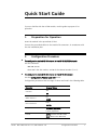
Quick Start Guide
If you are familiar with the HS-RN module, use this guide to prepare it for
operation.
1.
Preparation for Operation
Insert the module in the prescribed I/O slot.
Connect the prescribed cables to the module CH connectors, in accordance with
the site installation plan.
2.
³
Configuration Procedure
To configure the desired HS-RN channel in the MP-2100/2104 chassis:
Use the command:
DEF CH SS CC
where SS is the slot number, and CC is the channel number (1 to 4).
³
To configure the desired HS-RN channel in the MP-4100 chassis:
Use the Configuration>Physical Layer>I/O screen.
Configuration parameters and the range of values are listed in the following table.
Parameter
Connect*
Admin Status**
Bus Connection*
Encapsulation Mode
Range of Values
YES
NO
UP
DOWN
FULL
PARTIAL
Bandwidth Optimized
Latency Optimized
Format
ASYNC (Default with MP-2100)
SYNC (Default with MP-4100)
HS-RN
MP-2100/2104 Ver. 12.6, MP-4100 Ver. 2.0
Configuration Procedure
1
Quick Start Guide
Installation and Operation Manual
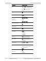
Parameter
Range of Values
Rate
ASYNC: 0.6, 1.2, 2.4, 4.8, 7.2,
9.6, 14.4, 19.2, 28.8, 38.4 kbps
SYNC: 0.6, 1.2, 2.4, 4.8, 7.2, 9.6,
14.4, 19.2, 28.8, 38.4, 56,
64 kbps
CTS
DCD & DSR
ON
RTS
LOCAL
END-TO-END
5 BITS (MP-2100)
Data Bits
(ASYNC only)
6 BITS
7 BITS
8 BITS (MP-4100)
Parity (ASYNC only)
YES
NO
Stop Bits
(ASYNC only)
1
Clock Mode (SYNC only)
DCE
2
EXT DCE
Oper Mode
BI-DIR
UNI-BRD TX
UNI-BRD RX
BID-BRD RX*
ML Slot*
IO-1 up to the maximum
supported by the chassis
ML Channel*
EX1 up to the maximum
supported by the selected main
link module
Link to Slot**
CL.1, IO-1 to IO-10
Link to Port**
1 to 8 for external ports
1 to 63 (1 to 84) for internal
(virtual) PDH ports
NONE
N/A
Map Type
USER
SEQUENCE
2
Configuration Procedure
HS-RN
MP-2100/2104 Ver. 12.6, MP-4100 Ver. 2.0
Installation and Operation Manual
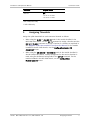
Quick Start Guide
Parameter
Range of Values
Start TS
N/A
1 to 31 for E1 links
1 to 24 for T1 links
* MP-2100/2104 only
** MP-4100 only
3.
Assigning Timeslots
Assign the uplink bandwidth to each connected channel as follows:
HS-RN
•
When using the BI-DIR or UNI-BRD TX mode in the module installed in the
MP-2100/2104 chassis, use the DEF TS command to assign a timeslot and the
DEF SPLIT TS A:B:C command to assign a fraction of a timeslot as explained in
the Megaplex-2100/2104 Installation and Operation Manual. For the module
installed in the MP-4100 chassis, use the Configuration>System>TS
Assignment screen.
•
When using the UNI-BRD RX or BID-BRD RX mode in the module installed in
the MP-2100/2104 chassis, timeslot assignment for the receive direction is
made using the dedicated routing fields of the DEF CH command. For the
module installed in the MP-4100 chassis, use the Configuration>
Physical Layer>IO screen.
MP-2100/2104 Ver. 12.6, MP-4100 Ver. 2.0
Assigning Timeslots
3
Quick Start Guide
4
Assigning Timeslots
Installation and Operation Manual
HS-RN
MP-2100/2104 Ver. 12.6, MP-4100 Ver. 2.0
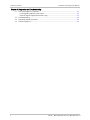
Contents
Chapter 1. Introduction
1.1
1.2
1.3
1.4
1.5
Overview.................................................................................................................... 1-1
Product Options...................................................................................................... 1-1
Main Features ......................................................................................................... 1-1
Applications ............................................................................................................... 1-2
Low-Speed Data Connectivity.................................................................................. 1-2
Unidirectional Broadcast Mode Applications ............................................................ 1-3
Bidirectional Broadcast Mode Applications (MP-2100/2104) .................................... 1-5
Physical Description ................................................................................................... 1-7
Functional Description................................................................................................ 1-8
Functional Block Diagram ........................................................................................ 1-8
TDM Bus Interfaces (Megaplex-2100/2104 only) ..................................................... 1-9
Routing Matrix ........................................................................................................ 1-9
Encapsulation Mode ................................................................................................ 1-9
Channel Rates....................................................................................................... 1-10
Channel Rate Adaptation Processor....................................................................... 1-10
Channel Interface.................................................................................................. 1-11
Channel Interface Functions ............................................................................. 1-11
Asynchronous Mode ......................................................................................... 1-11
Synchronous Mode........................................................................................... 1-12
Interface Control Lines ..................................................................................... 1-12
Timing .................................................................................................................. 1-12
Configuration and Management ............................................................................ 1-13
Diagnostics ........................................................................................................... 1-13
Technical Specifications............................................................................................ 1-13
Chapter 2. Installation and Operation
2.1
2.2
2.3
2.4
Introduction ............................................................................................................... 2-1
Installing the Module in the Chassis ............................................................................ 2-1
Connecting the Cables................................................................................................ 2-2
Connection Data ..................................................................................................... 2-2
Connector Pin Assignment .................................................................................. 2-2
Cable Data ......................................................................................................... 2-3
Cable Connections .................................................................................................. 2-3
Normal Indications ..................................................................................................... 2-4
Chapter 3. Configuration
3.1
3.2
3.3
3.4
3.5
3.6
HS-RN
Introduction ............................................................................................................... 3-1
Configuration Sequence for the MP-2100/2104 Chassis.............................................. 3-1
Configuration Sequence for the MP-4100 Chassis ....................................................... 3-2
Configuration Parameters........................................................................................... 3-2
Assigning Timeslots .................................................................................................... 3-6
Displaying Status and Configuration Information ........................................................ 3-7
MP-2100/2104 Ver. 12.6, MP-4100 Ver 2.0
i
Table of Contents
Installation and Operation Manual
Chapter 4. Diagnostics and Troubleshooting
4.1
4.2
4.3
4.4
ii
Test and Diagnostic Functions .................................................................................... 4-1
Local Digital Loopback (Local Loop) ......................................................................... 4-1
Remote Digital Loopback (Remote Loop)................................................................. 4-1
Troubleshooting ......................................................................................................... 4-3
Frequently Asked Questions ....................................................................................... 4-3
Technical Support ...................................................................................................... 4-4
HS-RN
MP-2100/2104 Ver. 12.6, MP-4100 Ver 2.0
Chapter 1
Introduction
1.1
Overview
This manual describes the technical characteristics, applications, installation and
operation of the HS-RN four-channel low-speed data modules for use in
Megaplex-2100, Megaplex-2104, and Megaplex-4100 integrated access
multiplexers.
HS-RN modules provide functionality similar to that offered by the HS-R modules
long available from RAD, but use improved hardware that can utilize all the four
TDM buses in the chassis (a capability supported only by Megaplex units equipped
with CL.2 modules and running software version 11.0 and higher).
Product Options
Two module versions are offered:
Note
•
HS-RN: a proprietary HDLC-protocol based module version featuring
Bandwidth and Latency optimization.
•
HS-RN/V.110: a special version for operation in the V.110 mode, fully
compatible with the old HS-R module.
In this manual, the following generic terms are used:
• The term HS-RN is used when the information is applicable to both the HS-RN
and HS-RN/V.110 modules.
• The term Megaplex is used when the information is applicable to all the three
Megaplex chassis.
The complete designation is used only for information applicable to a specific
equipment version.
Main Features
The HS-RN modules provide four independent V.24/RS-232 channels with DCE
interfaces that support full duplex asynchronous and synchronous data
transmission in the range of 0.6 through 64 kbps. The supported data rates
depend on the HS-RN model and encapsulation method (see Table 1-1).
Each channel has local support of RS-232 control signals. Alternately, each
channel can be configured to transmit RS-232 control signals end-to-end (this is
possible at all the rates, except for 56 and 64 kbps):
HS-RN
MP-2100/2104 Ver. 12.6, MP-4100 Ver. 2.0
Overview
1-1
Chapter 1 Introduction
Installation and Operation Manual
•
The local DTR state determines the remote DSR state, and vice versa
•
The local RTS state determines the remote DCD state, and vice versa.
Basically, each HS-RN channel is assigned an individual timeslot in the E1, T1 or
SDH/SONET uplink. The HS-RN modules also support split timeslot assignment,
therefore improving uplink bandwidth utilization.
The user can assign the timeslots and timeslot bits to HS-RN channels manually.
User-controlled manual timeslot assignment allows routing the bit stream
generated by each local channel to any other compatible Megaplex channel at the
remote site.
In addition to the normal full-duplex (bidirectional) mode, HS-RN supports
additional transmission modes, which enable point-to-multipoint communication:
•
Unidirectional (simplex) transmission, where each channel can be configured
either to receive (unidirectional RX) or transmit (unidirectional TX).
•
Bidirectional broadcast (half-duplex) communication, suitable for polled
applications. In this mode, a channel can either transmit or receive, but not
both simultaneously (the direction of transmission is determined by the state
of the local RTS line). This mode is not supported by the Megaplex-4100
chassis.
For a description of these modes, see the corresponding Megaplex Installation
and Operation Manual.
The operation mode of each channel is independently selectable, using the
Megaplex management system or a supervision terminal.
The HS-RN modules perform rate adaptation using a proprietary HDLC-based
protocol, while the HS-RN/V.110 modules perform rate adaptation in accordance
with ITU-T Rec. V.110. Multiplexing in both models is performed in accordance
with ITU-T Rec. I.460.
1.2
Applications
Low-Speed Data Connectivity
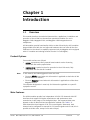
Figure 1-1 shows a typical point-to-point low-speed data transmission application
using HS-RN modules.
In this application, two HS-RN modules are used to connect remote terminals to a
server or communication controller through the Megaplex link. Each channel can
be connected to a different destination.
The HS-RN modules enable efficient utilization of link bandwidth; for example, a
HS-RN module enables the transmission of all the four 9.6 kbps channels in one
64 kbps timeslot (see Section 1.4 for additional details).
1-2
Applications
HS-RN
MP-2100/2104 Ver. 12.6, MP-4100 Ver. 2.0
Installation and Operation Manual
Chapter 1 Introduction
Figure 1-1. Low-Speed Data Connection
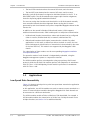
Figure 1-2 shows a typical Point-to-Multipoint application.
Figure 1-2. Point-to-Multipoint Connectivity at Low Speed Data Transfer
Unidirectional Broadcast Mode Applications
The unidirectional broadcast mode enables a user at a central location to send
data to multiple users connected to remote Megaplex units (simplex
communication), while using only one timeslot.
In this mode, any message is simultaneously received by all the unidirectional
users, but none of them can send back data to the originator.
This capability is achieved by separating the handling of the receive and transmit
paths in the timeslot assigned for the unidirectional channels, as shown by the
dashed lines within the Megaplex units in Figure 1-3.
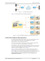
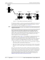
Figure 1-3 shows a network that uses the unidirectional broadcast mode to
distribute data from a central location (A) to several remote locations (B, C, D,
etc.). In Figure 1-3, the user at the central location (A) is connected to an HS-RN
channel configured for operation in the unidirectional transmit mode. The
channels of the remote users (at locations B, C, D) are configured for the
unidirectional receive mode.
HS-RN
MP-2100/2104 Ver. 12.6, MP-4100 Ver. 2.0
Applications
1-3
Chapter 1 Introduction
Installation and Operation Manual
The timeslot assigned to user A on one of the internal TDM buses is routed to the
two main link ports of the Megaplex unit at location A, and can be inserted in
timeslots with different numbers.
For simplicity, first the path to the user at location D is described:
•
In the forward path (from location A to D), the timeslot assigned to the
HS-RN channel configured for unidirectional transmit operation is routed
through the desired timeslot of port 1 to the Megaplex unit at location D.
At location D, the timeslot is routed to the HS-RN channel is routed to the
receive path of the unidirectional receive HS-RN channel. Therefore, the user
D receives data sent by user A.
•
In the reverse path (from location D to A), the timeslot is always
disconnected. Therefore, the user D cannot transmit data to user A.
Location D
HS-RN
(Unidirectional RX)
Location A
HS-RN
(Unidirectional TX)
Megaplex
Port 1
Location C
Port 2
HS-RN
(Unidirectional RX)
Location B
Megaplex
Port 1 Port 2
Megaplex
Megaplex
HS-RN
(Unidirectional RX)
User's Equipment
(Receive Only)
Figure 1-3. Typical Unidirectional Broadcast Application
The path to the users B and C is as follows:
•
In the forward path (from location A to B, C, etc.), the timeslot assigned to
the HS-RN channel configured for unidirectional transmit operation is routed
through the desired timeslot of port 2 to the Megaplex unit at location B.
At location B, the timeslot received at port 1 is routed as follows:
To the receive path of user B, configured for unidirectional receive
operation
To the desired timeslot of port 2 (bypassing), which is connected to the
Megaplex at location C.
Therefore, the transmit signal of user A is relayed to the following units, and
the user B receives data sent by user A.
1-4
Applications
HS-RN
MP-2100/2104 Ver. 12.6, MP-4100 Ver. 2.0
Installation and Operation Manual
Note
Chapter 1 Introduction
The timeslot can be connected in parallel to any number of channels.
•
In the reverse path (to location A), the timeslot is always bypassed from port
2 to port 1, en route to location A.
To prevent interference from the unidirectional channel, its transmit path is
always disconnected from the main link timeslots (at location B, no
information is inserted in the timeslot bypassed from port 2 to port 1), and
user B cannot transmit data to any other user. The same is true for the user
at location C.
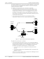
Figure 1-4 shows another network configuration, which enables regular (full
duplex, or bidirectional) communication between two users (the users at
locations A and C), and in addition enables the monitoring of the data sent by
the user at location A at location B.
For this configuration, the users A and C are configured as regular users, and the
user at location B is configured for unidirectional receive operation.
Location A
Location C
HS-RN
(Bidirectional)
HS-RN
(Bidirectional)
Location B
Port 1
Port 2
Megaplex
Megaplex
Megaplex with
2 Main Links
HS-RN
(Unidirectional RX )
User's Equipment
(Receive Only)
Figure 1-4. Typical Unidirectional Receive Application
Bidirectional Broadcast Mode Applications (MP-2100/2104)
The bidirectional broadcast mode enables a user at a central location to
communicate half-duplex with several users connected to remote Megaplex units.
Figure 1-5 shows a network topology which uses the bidirectional broadcast
capability.
HS-RN
MP-2100/2104 Ver. 12.6, MP-4100 Ver. 2.0
Applications
1-5
Chapter 1 Introduction
Installation and Operation Manual
Location A
HS-RN
(Bidirectional)
Port 1
Port 2
Port 1
RX
TX
Location D
Location C
Location B
Megaplex with
2 Main Links
Port 1
Port 3
RX
TX
HS-RN
(Bidirectional)
Port 3
Megaplex with
2 Main Links
HS-RN
(Bidirectional
Broadcast RX)
Port 1
Port 2
HS-RN
(Bidirectional
Broadcast RX)
Megaplex with
2 Main Links
Figure 1-5. Typical Bidirectional Broadcast Application
The broadcast capability is achieved by separating the handling of the receive and
transmit paths for the timeslots assigned for the broadcast channels, as shown
by the dashed lines within the Megaplex units in Figure 1-5.
Note
The bidirectional broadcast mode is not available for the module operating in the
Megaplex-4100 chassis.
The user at the central location is configured to use the regular (bidirectional)
mode, and therefore it can both transmit and receive. The other users are
configured to use the bidirectional broadcast receive (BID BRD RX) mode: this
mode is similar to the unidirectional receive mode, except that at any time one of
these users (and only one) can transmit to (and be received by) user A. This
mode of operation is used in polled applications.
In the application shown in Figure 1-5, the handling of the signals generated by user
A is similar to that for the unidirectional transmit mode described above. The
difference is that each broadcast user can insert its signal in the receive timeslot that
reaches user A (instead of the signal bypassed from the other link). The change in
routing is controlled by the RTS signal in the data connector of the HS-RN module:
•
When the RTS signal is not active (idle state), the receive timeslot is bypassed
from link B to link A, and continues toward user A.
•
When the RTS signal is asserted, the receive timeslot of link B is disconnected
from link A, and the transmit path of the local broadcast user is connected to
link A.
Thus, user A can request any user to answer, and that user can assert its RTS line
and thus connect to user A. At any time, only one user may transmit toward user A
(if more than one user transmits, only the user closest to location A will actually be
received). When using the bidirectional broadcast receive mode, it is necessary to
instruct each main link port how to handle the traffic flow information. This is
performed by defining the timeslot type, as part of the DEF TS command (see
Megaplex-2100/2104 Installation and Operation Manual).
1-6
Applications
HS-RN
MP-2100/2104 Ver. 12.6, MP-4100 Ver. 2.0
Installation and Operation Manual
1.3
Chapter 1 Introduction
Physical Description
The HS-RN is a 4U-high module that occupies one I/O module slot in the
Megaplex chassis. All the functional configuration parameters of the modules are
determined by software. Jumpers are used only to control the connection of
ground reference to each channel connector.
Figure 1-6 shows a typical HS-RN panel.
HS-RN
TST LOS
CH.1
Test
Indicators
CH.2
CH.3
LOS
Indicators
CH.4
CH1 & CH2 Connector
Channels
1-2
CH.
1-2
CH3 & CH4 Connector
Channels
3-4
CH.
3-4
Figure 1-6. Typical HS-RN Module Panel
The HS-RN panel includes two status indicators for each channel:
•
TST (yellow): lights up when a test or loopback is activated on the
corresponding channel.
•
LOS (red): lights up when the main link loses synchronization or the
corresponding channel loses protocol synchronization to the remote end (not
used for the rates of 64 kbps and 56 kbps)
When a channel is not connected, its LOS indicator is always off.
The HS-RN module panel also includes two 25-pin D-type female connectors,
each serving two channels.
HS-RN
MP-2100/2104 Ver. 12.6, MP-4100 Ver. 2.0
Functional Description
1-7
Chapter 1 Introduction
Installation and Operation Manual
1.4
Functional Description
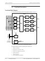
Functional Block Diagram
The functional block diagram of the HS-RN module is shown in Figure 1-7.
HS-RN
Sync/Async
Channel 1
Rate
Adaptation
TDM
Bus A
Interface
Sync/Async
TDM
Bus B
Interface
TDM Bus D
TDM Bus C
TDM Bus B
TDM Bus A
TDM
Bus C
Interface
Channel
Interface 1
(Port EX1)
Channel 2
Rate
Adaptation
Routing
Matrix
CH. 1-2
Connector
Channel
Interface 2
(Port EX2)
Sync/Async
Channel 3
Rate
Adaptation
TDM
Bus D
Interface
Channel
Interface 3
(Port EX3)
Sync/Async
Channel 4
Rate
Adaptation
CH. 3-4
Connector
Channel
Interface 4
(Port EX4)
Management
Channel
Control
Local
Management
To CL
Module
Internal
Timing
Generator
Timing and
Clock Signals
Internal
Clock & Timing
Signals
Figure 1-7. Module HS-RN, Functional Block Diagram
The HS-RN module includes the following main subsystems:
1-8
•
TDM bus interfaces
•
Routing (cross-connect) matrix
•
Channel rate adaptation processor
•
Channel interfaces
•
Timing subsystem
•
Local management subsystem.
Functional Description
HS-RN
MP-2100/2104 Ver. 12.6, MP-4100 Ver. 2.0
Installation and Operation Manual
Chapter 1 Introduction
TDM Bus Interfaces (Megaplex-2100/2104 only)
The HS-RN module has four independent TDM bus interfaces, one for each
Megaplex-2100/2104 TDM bus. Each TDM bus interface is used to connect
timeslots from the corresponding bus to the internal routing matrix of the HS-RN
module, in accordance with the commands received from the CL module.
HS-RN can use all the four TDM buses. However, when necessary the
Megaplex-2100/2104 user can configure it to use only two TDM bus interfaces,
irrespective of the number of TDM buses used in the Megaplex-2100/2104
chassis.
Note
The default number of TDM buses used in the MP-2100/2104 chassis is 4. The
number can be reduced by means of the SET USER command. The HS-RN module
can be configured to use all the four TDM buses only when the number of
MP-2100/2104 TDM buses has not been reduced.
Routing Matrix
The HS-RN module includes a routing matrix that controls the routing of the
module channels to the desired Megaplex main link ports, via the TDM buses.
The matrix also supports split timeslot routing: it enables inserting any channel
not requiring a full timeslot in any position of a desired timeslot (see number of
required bits versus channel data rate in Table 1-2).
Matrix routing is controlled by the CL module, and enables connecting any TDM
bus timeslot to any channel. The routing matrix also supports unidirectional
routing of timeslots, and broadcasting from one timeslot to multiple destinations
(refer to the corresponding Megaplex Installation and Operation Manual for
details).
Encapsulation Mode
In the HDLC module version, the module encapsulation mode can be optimized
according to the user application as follows:
•
Bandwidth Optimized – enables uplink bandwidth optimization (using split
timeslots) in applications less sensitive to latency.
•
Latency Optimized – enables minimum end-to-end data latency. In this mode
split timeslots are not available, and the uplink bandwidth should be always
transferred over full 64 kbps timeslot per channel.
In the V.110 module version, the module operates in Bandwidth Optimized mode
only, but the end-to-end data latency is at minimum.
Note
HS-RN
A pair of HS-RN modules can operate together only if set to the same mode
(HDLC/BO, HDLC/LO or V110).
MP-2100/2104 Ver. 12.6, MP-4100 Ver. 2.0
Functional Description
1-9
Chapter 1 Introduction
Installation and Operation Manual
Channel Rates
Table 1-1 lists the HS-RN data rates available in the V.110 and HDLC operating
modes.
Table 1-1. HS-RN Channel Rates in HDLC and V.110 Operating Modes
Channel Rate
HDLC - Bandwidth Optimized
HDLC - Latency Optimized
V.110
Sync
Async
Sync
Async
Sync
Async
0.6 kbps
√
√
√
√
√
√
1.2 kbps
√
√
√
√
√
√
2.4 kbps
√
√
√
√
√
√
4.8 kbps
√
√
√
√
√
√
7.2 kbps
√
√
√
√
9.6 kbps
√
√
√
√
√
√
14.4 kbps
√
√
√
√
19.2 kbps
√
√
√
√
√
√
28.8 kbps
√
√
38.4 kbps
√
√
√
√
56 kbps
√
√
64 kbps
√
√
Channel Rate Adaptation Processor
Rate adaptation is needed at all the channel rates, except 56 and 64 kbps. Each
channel has its own channel rate adaptation processor, which is used to adapt
the user’s payload data rate to a multiple of 16 kbps (16 kbps, or two bits, is the
main link bandwidth allocation unit).
The difference between the assigned and payload bandwidth also enables
end-to-end transfer of RS-232 interface signal states, when a channel is
configured to support this service.
Table 1-2 lists the supported user's payload data rates, the data rate obtained
after rate adaptation, the number of main link bits assigned by the HS-RN
channel to carry the channel payload data, and the corresponding fraction of
main link timeslot for each data rate.
Note
When a channel operates in any one of the broadcast modes or latency
optimization mode, it must be assigned a full main link timeslot, although it may
not utilize the full timeslot bandwidth.
To assign a fraction of a timeslot for the module installed in the MP-2100/2104
chassis, use a DEF SPLIT TS A:B:C command, as explained in the
Megaplex-2100/2104 Installation and Operation Manual. For the module installed
in the MP-4100 chassis, use the Configuration>System>TS Assignment screen.
1-10
Functional Description
HS-RN
MP-2100/2104 Ver. 12.6, MP-4100 Ver. 2.0
Installation and Operation Manual
Chapter 1 Introduction
For completeness, Table 1-2 also lists rates at which rate adaptation is not
needed (56 and 64 kbps).
Table 1-2. Occupied Bandwidth versus Channel Rate
Channel Rate
Occupied Bandwidth
Number of Bits
0.6 kbps
16 kbps
2 (one-quarter timeslot)
1.2 kbps
16 kbps
2 (one-quarter timeslot)
2.4 kbps
16 kbps
2 (one-quarter timeslot)
4.8 kbps
16 kbps
2 (one-quarter timeslot)
7.2 kbps
16 kbps
2 (one-quarter timeslot)
9.6 kbps
16 kbps
2 (one-quarter timeslot)
14.4 kbps
32 kbps
4 (one-half timeslot)
19.2 kbps
32 kbps
4 (one-half timeslot)
28.8 kbps
64 kbps
8 (one timeslot)
38.4 kbps
64 kbps
8 (one timeslot)
56 kbps (SYNC mode only)
64 kbps
8 (one timeslot)
64 kbps (SYNC mode only)
64 kbps
8 (one timeslot)
Channel Interface
Channel Interface Functions
Each HS-RN module channel can be configured by the user for asynchronous or
synchronous operation. Each channel has a DCE RS-232 interface.
The channel interface provides the following functions:
•
Conversion of data stream received from the link to the format needed by
the user’s equipment, and vice versa. This conversion depends on the
operation mode (synchronous/asynchronous; for the latter, it also depends
on the selected word format.
•
Physical interfacing to the user’s equipment, including handling of RS-232
interface signals.
Asynchronous Mode
The data rates supported by both HS-RN models in the asynchronous mode are
0.6, 1.2, 2.4, 4.8, 9.6, 19.2, and 38.4 kbps. The HDLC model additionally features
the data rates of 7.2, 14.4 and 28.8 kbps.
In the asynchronous mode, the user can specify the structure of the word format
to be processed by each channel (this structure must be identical to that used by
the user's equipment).
The available options are as follows:
•
HS-RN
Number of data bits: 5, 6, 7, or 8.
MP-2100/2104 Ver. 12.6, MP-4100 Ver. 2.0
Functional Description
1-11
Chapter 1 Introduction
Installation and Operation Manual
•
Use of parity: if the user's data word format includes a parity bit, the user
can enable transparent end-to-end transfer of the original parity bit. The HSRN module itself does not check the parity of the incoming data.
•
Number of stop bits: 1 or 2.
In addition to the selected parameters, the word format includes one start bit.
Note
When setting the Async Mode parameters, pay attention to the total character
length calculated by the formula: M=data bits + parity + 1 start bit + stop bits.
This length can be set to 8,9,10, or 11. The numbers out of this range are not
supported.
Synchronous Mode
The data rates supported by both HS-RN models in the synchronous mode are
0.6, 1.2, 2.4, 4.8, 9.6, 19.2, 38.4, 56 and 64 kbps. The HDLC model additionally
features the data rates of 7.2, 14.4 and 28.8 kbps.
Interface Control Lines
The RS-232 interface control signals are locally supported in accordance with the
RS-232 protocol, with the following modifications:
•
The DSR line is continuously active (ON), except when the end-to-end
transmission of control signals is enabled.
•
The DCD line is ON only when both the channel framing machine and the local
Megaplex main link carrying the channel are synchronized, and is OFF when
either the channel framing machine or the main link loses synchronization.
•
For flexibility in application, the user can program the state of the CTS line.
The available selections are:
The CTS line is continuously active (ON).
The state of the local CTS line tracks the state of the local RTS line.
As an alternative to local support as described above, the user can enable
end-to-end transmission of the states of the local DTR and RTS lines to the
remote DSR and DCD lines, respectively. Note that end-to-end transmission of
control signals is not supported at the 56 and 64 kbps channel rates.
Timing
When operating in the synchronous mode, the timing of the HS-RN channel
interfaces is locked to the Megaplex nodal timing.
The timing mode of each HS-RN module channel can be selected by the user. Two
options are available:
1-12
•
DCE: the interface provides transmit and receive clock signals to the user's
data equipment (DTE). The user's DTE must receive and transmit at the rate
of the clock signals provided by the HS-RN channel interface.
•
EXT DCE: the interface provides a receive clock signal to the user's DTE, and
accepts the transmit clock from the user's DTE. The user's DTE must operate
with loopback timing; that is, it must transmit at the rate of the receive clock
Functional Description
HS-RN
MP-2100/2104 Ver. 12.6, MP-4100 Ver. 2.0
Installation and Operation Manual
Chapter 1 Introduction
signal provided by the HS-RN channel interface. This timing mode is suitable
for tail-end applications.
Configuration and Management
All the module operating parameters are controlled by means of the Megaplex
system management. The flexible timeslot routing capabilities of the Megaplex
systems enable the user to select the timeslots assigned to HS-RN channels on
the E1/T1/SDH/SONET uplinks, in order to route the bit stream generated by the
multiplexing process described above in each local channel.
Each main link allocation unit generated by an HS-RN module can be
independently routed to any other compatible module installed in the remote
Megaplex unit, configured for the same combination of data rates. Moreover, the
HS-RN modules support split timeslot allocation.
Diagnostics
The HS-RN modules support self-diagnostics upon power-up, as well as powerful
testing capabilities controlled by means of the system management functions.
The test and loopback functions, that can be individually activated by the system
management functions for each module channel, include:
•
Local digital loopback.
•
Remote digital loopback.
1.5
General
Technical Specifications
Number of data
channels
Four
Channel interface
ITU-T Rec. V.24/V.28, EIA RS-232
Interface type
DCE
Signal format
Asynchronous or synchronous, user-selectable
Number of TDM 2 or 4, user selectable (4 buses are supported only by Megaplex-2100/2104
Buses in
units equipped with CL.2 modules and running software version 11.0 and
MP-2100/2104 higher)
HS-RN
MP-2100/2104 Ver. 12.6, MP-4100 Ver. 2.0
Technical Specifications
1-13
Chapter 1 Introduction
Data
Transmission
Characteristics
Installation and Operation Manual
Asynchronous
mode
0.6, 1.2, 2.4, 4.8, 7.2*, 9.6, 14.4*, 19.2, 28.8*,
38.4 kbps
Synchronous mode 0.6, 1.2, 2.4, 4.8, 7.2*, 9.6, 14.4*, 19.2, 28.8*, 38.4, 56,
64 kbps
Notes: 1. The rates marked by asterisk (*) are supported in the
HDLC model only. 2. When Encapsulation mode is “Latency
optimized”, only rates up to 19.2 are supported.
Asynchronous
character format
Interface
Control Signals
User-selectable
Start bits
1
Data bits
5, 6, 7, or 8
Parity
Enable/disable transparent end-to-end transfer of parity
bit
Stop bits
1 or 2
Support modes
• Local support
• End-to-end transfer (not available for rates of 56 and
64 kbps)
Local support
• DSR always ON when module is powered (unless
end-to-end transmission is enabled)
• Local DCD is ON when the main link is synchronized
and there is no SYNC LOSS alarm on the channel
• Local CTS tracks local RTS state, or is constantly ON
(user-selectable)
End-to-end transfer • Local DTR line to remote DSR line
(user-selectable)
• Local RTS line to remote DCD line
Timing
Timing source
RS-232 interface timing locked to nodal timing
Timing modes
• DCE: Transmit and receive clocks to DTE
• External DCE: Receive clock to DTE, transmit clock from
DTE
Main Link
Bandwidth
• 2 bits for 0.6, 1.2, 2.4, 4.8, 7.2, 9.6 kbps
• 4 bits for 14.4, 19.2 kbps
• 8 bits for 28.8, 38.4, 56, 64 kbps (one timeslot per channel)
1-14
Technical Specifications
HS-RN
MP-2100/2104 Ver. 12.6, MP-4100 Ver. 2.0
Installation and Operation Manual
Indicators
Diagnostics
Chapter 1 Introduction
LOS indicator (per
channel)
Lights up when the main link loses synchronization or the
corresponding channel loses protocol synchronization to
the remote end (not used for the rates of 56 and
64 kbps)
TEST indicator (per
channel)
Lights up when a loopback is activated on the
corresponding channel
Loopbacks
• Local loopback
• Remote loopback
Connectors
Two 25-pin D-type female connectors (one connector for
each pair of channels)
Configuration
Programmable by the Megaplex system management
HS-RN
MP-2100/2104 Ver. 12.6, MP-4100 Ver. 2.0
Technical Specifications
1-15
Chapter 1 Introduction
1-16
Technical Specifications
Installation and Operation Manual
HS-RN
MP-2100/2104 Ver. 12.6, MP-4100 Ver. 2.0
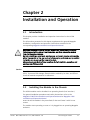
Chapter 2
Installation and Operation
2.1
Introduction
This chapter provides installation and operation instructions for the HS-RN
modules.
The information presented in this chapter supplements the general Megaplex
installation, configuration and operation instructions contained in the
corresponding Megaplex Installation and Operation Manual.
Warning
Before performing any internal settings, adjustment, maintenance, or repairs,
first disconnect all the cables from the module, and then remove the module
from the Megaplex enclosure.
No internal settings, adjustment, maintenance, and repairs may be performed by
either the operator or the user; such activities may be performed only by a skilled
technician who is aware of the hazards involved.
Always observe standard safety precautions during installation, operation, and
maintenance of this product.
Caution
The HS-RN module contains components sensitive to electrostatic discharge
(ESD). To prevent ESD damage, always hold the module by its sides, and do not
touch the module components or connectors.
2.2
Installing the Module in the Chassis
The HS-RN modules can be installed in an operating chassis (hot insertion).
For general installation procedures and safety instructions, refer to the
Megaplex-2100/2104 Installation and Operation Manual or Megaplex-4100
Installation and Operation Manual.
Insert the HS-RN module in the prescribed I/O slot and fasten it with its two
screws.
The module starts operating as soon as it is plugged into an operating Megaplex
enclosure.
HS-RN
MP-2100/2104 Ver. 12.6, MP-4100 Ver. 2.0
Connecting the Cables
2-1
Chapter 2 Installation and Operation
2.3
Installation and Operation Manual
Connecting the Cables
Connection Data
Connector Pin Assignment
The connection of user’s equipment to HS-RN modules is made to the two 25-pin
D-type female connectors designated CH. 1-2 and CH. 3-4. Table 2-1 lists the pin
assignment of the CH. 1-2 connector, which serves channels 1 and 2. The wiring of
the CH. 3-4 connector, which serves channels 3 and 4, is similar.
Table 2-1. CH. 1-2 Connector, Pin Assignment
Pin
Designation
Function
1
FGND
–
Frame ground (connected through jumper)
2
TD1
IN
TX data, channel 1
3
RD1
OUT
RX data, channel 1
4
RTS1
IN
5
CTS1
OUT
Clear to send, channel 1
6
DSR1
OUT
Data set ready, channel 1
7
SGND
–
8
DCD1
OUT
9, 10
2-2
Direction
–
–
Request to send, channel 1
Signal ground
Carrier detect, channel 1
Not used
11
TXCLK2
OUT
TX clock, channel 2
12
DCD2
OUT
Carrier detect, channel 2
13
CTS2
OUT
Clear to send, channel 2
14
TD2
IN
TX data, channel 2
15
TXCLK1
OUT
TX clock, channel 1
16
RD2
OUT
RX data, channel 2
17
RCLK1
OUT
RX clock, channel 1
18
RCLK2
OUT
RX clock, channel 2
19
RTS2
IN
Request to send, channel 2
20
DTR1
IN
Data terminal ready, channel 1
21
DSR2
OUT
Data set ready, channel 2
22
–
–
Not used
23
TXCLK-EXT2
IN
External TX CLK, channel 2
24
TXCLK-EXT1
IN
External TX CLK, channel 1
25
DTR2
IN
Data terminal ready, channel 2
Connecting the Cables
HS-RN
MP-2100/2104 Ver. 12.6, MP-4100 Ver. 2.0
Installation and Operation Manual
Chapter 2 Installation and Operation
Cable Data
RAD offers two channel splitter cables that enable direct connection of data
equipment with RS-232 interfaces to an HS-RN channel connector:
•
CBL-HSR/F, which terminates into two 25-pin D-type female connectors.
•
CBL-HSR/M, which terminates into two 25-pin D-type male connectors.
The wiring diagram of the two cables is shown in Figure 2-1.
TD1
2
2
RD1
3
3
RTS1
4
4
CTS1
5
5
DSR1
6
6
DCD1
8
8
XCLK1
15
15
RCLK1
17
17
DTR1
20
20
XCLK-EXT1
24
24
GND
7
7
Channel 1
.
.
.
To HS-RN Port
Connector
TD2
14
2
RD2
16
3
RTS2
19
4
CTS2
13
5
DSR2
21
6
DCD2
12
8
XCLK2
11
15
RCLK2
18
17
DTR2
25
20
XCLK-EXT2
23
.
.
24
Channel 2
7
User's Equipment
Side
Module
Side
Figure 2-1. Channel Splitter Cable Wiring
Cable Connections
³
To connect the cables:
1. Identify the cables intended for connection to each module connector and
connect them into the appropriate connectors.
HS-RN
MP-2100/2104 Ver. 12.6, MP-4100 Ver. 2.0
Connecting the Cables
2-3
Chapter 2 Installation and Operation
Installation and Operation Manual
2. When using any of the adapter cables, plug each channel connector at the
other end of the cable into the prescribed user’s equipment connector in
accordance with the site installation plan.
2.4
Normal Indications
The status of each HS-RN channel is indicated by a separate set of indicators.
The normal indications for an operational channel interface are as follows:
•
The LOS indicator must be off.
However, it lights up when the corresponding channel loses synchronization
to the HDLC or V.110 frames used by the rate adaptation protocol (received
from the remote end).
Note
When the channel operates at 56 or 64 kbps, no framing is used, and thus the
LOS indicator lights only when the Megaplex main link loses synchronization.
•
2-4
The TST indicator must be off, but may turn on when a loopback is activated
on the corresponding channel interface.
Normal Indications
HS-RN
MP-2100/2104 Ver. 12.6, MP-4100 Ver. 2.0
Chapter 3
Configuration
3.1
Introduction
This chapter provides configuration information for HS-RN modules installed in
the Megaplex-2100/2104 or Megaplex-4100 chassis. For general instructions and
additional configuration procedures, refer to the Megaplex-2100/2104
Installation and Operation Manual and Megaplex-4100 Installation and Operation
Manual, respectively.
The configuration is performed by means of the management system used to
control the Megaplex unit:
•
Supervision terminal or Telnet – refer to the Megaplex-2100/2104 Installation
and Operation Manual or Megaplex-4100 Installation and Operation Manual
for instructions.
•
Web browser – refer to the Megaplex-4100 Installation and Operation Manual
for instructions.
•
Network management system, e.g., the RADview network management
system – refer to the RADview User's Manual for instructions.
3.2
³
Configuration Sequence for the MP-2100/2104
Chassis
To configure an HS-RN module and put it into service:
1. Add an HS-RN module not yet installed in the Megaplex-2100/2104 chassis to
the database. This allows preconfiguring the module parameters, so that the
module will immediately start operating in the desired mode as soon as it is
installed in the enclosure. For the supervision terminal, use the DEF SYS
command.
2. Configure the HS-RN channel parameters:
To define the parameters of all the module channels on the supervision
terminal, type the command:
DEF CH SS *
To define the parameters of a desired channel on the supervision
terminal, type the command:
DEF CH SS CC
HS-RN
MP-2100/2104 Ver. 12.6, MP-4100 Ver. 2.0
3-1
Chapter 3 Configuration
Installation and Operation Manual
where SS is the slot number, and CC is the channel number (1 to 4). For the
parameter description, see Table 3-1.
Note
HS-RN modules are identified as HS-R by the Megaplex-2100/2104 management
system, including the supervisory terminal.
3. Configure the rate of each module port by assigning timeslots as described in
Section 3.5.
Note
Make sure to plan ahead the configuration sequence, because
Megaplex-2100/2104 databases can be updated only after correctly completing
the configuration activities: any sanity error will prevent saving the changes to
the database being modified.
3.3
³
Configuration Sequence for the MP-4100
Chassis
To configure an HS-RN module and put it into service:
1. Add an HS-RN module not yet installed in the Megaplex-4100 chassis to the
database. This allows preconfiguring the module parameters, so that the
module will immediately start operating in the desired mode as soon as it is
installed in the enclosure.
For the supervision terminal, use the Configuration>System>Card Type
screen.
2. Configure the CL or M8E1/M8T1 module port parameters (depending on the
HS-RN module application). For the configuration procedure, refer to the
appropriate Installation and Operation Manual.
3. Configure the HS-RN port parameters. For the supervision terminal, use the
Configuration>Physical Layer>I/O screen.
4. Configure the timeslot assignment of each module port, using the
Configuration>System>TS Assignment screen.
Note
Make sure to plan ahead the configuration sequence, because Megaplex-4100
databases can be updated only after correctly completing the configuration
activities: any sanity error will prevent saving the changes to the database being
modified.
3.4
Configuration Parameters
Each HS-RN channel (external port) can be independently configured in
accordance with the system requirements.
Table 3-1 explains the programmable parameters of the HS-RN channels, and
their ranges of values.
3-2
HS-RN
MP-2100/2104 Ver. 12.6, MP-4100 Ver. 2.0
Installation and Operation Manual
Chapter 3 Configuration
Table 3-1. Channel Parameters
Parameter
Function
Values
Connect
Determines whether the channel is
connected to the internal TDM buses
of the Megaplex chassis
NO
The channel is disconnected. You can still
program the desired parameters, so the
channel will be ready to operate when
needed.
YES
The channel is connected to a legacy main
link port, and can carry traffic.
(MP-2100/2104
only)
Default: NO
Admin Status
(MP-4100 only)
Used to enable/disable the flow of
traffic through the selected port
UP
The flow of traffic is enabled.
DOWN
The flow of traffic is disabled. This state
should be selected as long as the port
configuration has not yet been completed,
or when it is necessary to stop traffic flow
through the port.
Default: DOWN
Bus Connection
(MP-2104/2100
only)
Selects the number of TDM buses
that can be used by the module.
FULL
All the four TDM buses can be used.
PARTIAL
The module can use only two buses
This parameter is relevant only in
(either bus A or B), even if the number of
Megaplex units with CL.2 modules
TDM buses selected by means of the SET
running software version 11.0 or
USER command is greater.
higher; otherwise, only two TDM
Default: PARTIAL
buses (buses A or B) can be used, and
all the HS-RN channels are routed to
the same bus.
The selection made for one channel is
automatically applied to all the
channels (the last selection overrides
all prior selections).
The selected number cannot exceed
the number of the TDM buses
selected by means of the SET USER
command
Encapsulation
Mode
Controls the encapsulation mode
according to the user application in
the HDLC model.
Bandwidth Optimized – enables uplink bandwidth
optimization (using split timeslots) in applications
less sensitive to latency.
The V.110 model operates in
Bandwidth Optimized mode only,
but the end-to-end data latency is
at minimum.
Latency Optimized – enables minimum end-to-end
data latency. In this mode split timeslots are not
available and the uplink bandwidth should be
always transferred over full 64 kbps timeslots.
Default: Bandwidth Optimized
Format
Specifies the channel operating
mode
ASYNC
Asynchronous mode
SYNC
Synchronous mode
Default: ASYNC (MP-2100), SYNC (MP-4100)
HS-RN
MP-2100/2104 Ver. 12.6, MP-4100 Ver. 2.0
3-3
Chapter 3 Configuration
Installation and Operation Manual
Parameter
Function
Values
Rate
Specifies the channel data rate.
The range of selections is as follows:
Notes: 1. When Encapsulation mode
is “Latency optimized”, only rates up
to 19.2 are supported and occupying
the full timeslot bandwidth. 2. The
rates marked by asterisk (*) are
supported in the HDLC model only.
ASYNC mode:
0.6, 1.2, 2.4, 4.8, 7.2*, 9.6, 14.4*,
19.2, 28.8*, or 38.4 kbps.
SYNC mode:
0.6, 1.2, 2.4, 4.8, 7.2*, 9.6, 14.4*,
19.2, 28.8*, 38.4, 56, or 64 kbps.
Used to control the state of the CTS
line
The available selections are:
CTS
Default: 0.6 kbps
ON
The CTS line is continuously on.
RTS
The CTS line tracks the state of the local RTS
line.
Default: ON
DCD & DSR
Controls the end-to-end
transmission of the local DTR and
RTS lines to the remote DSR and
DCD lines, respectively
LOCAL
End-to-end transmission disabled,
only local support available.
Always use this selection for data
rates exceeding 38.4 kbps.
END-TO-END
End-to-end transmission enabled:
the state of the local RTS and DTR
lines are reflected by the remote
DCD and DSR line, respectively. Do
not use this selection for data
rates exceeding 38.4 kbps.
Default: LOCAL
Data Bits*
Parity*
Selects the number of data bits.
The available selections are 5, 6, 7, or 8 bits.
This parameter is displayed only
when operating in the asynchronous
mode
Default: 8 BITS (MP-4100), 5 BITS (MP-2100/2104)
Used to control the end-to-end
transfer of the parity bit.
The available selections are:
YES
The parity bit is transparently transferred
end-to-end. This selection is relevant only
when the user’s equipment generates a
parity bit.
NO
The parity bit is not transferred.
This parameter is displayed only
when operating in the asynchronous
mode
Default: NO
Stop Bits*
Used to select the number of stop
bits.
The available selections are 1 or 2 bits.
Default: 1
This parameter is displayed only
when operating in the asynchronous
mode
* When setting the Async Mode parameters, pay attention to the total character length calculated by the
formula: M=data bits + parity + 1 start bit + stop bits. This length can be set to 8,9,10, or 11. The numbers
out of this range are not supported.
3-4
HS-RN
MP-2100/2104 Ver. 12.6, MP-4100 Ver. 2.0
Installation and Operation Manual
Chapter 3 Configuration
Parameter
Function
Values
Clock Mode
Used to control the clock mode in
the synchronous mode.
The available selections are:
This parameter is displayed only
when operating in the synchronous
mode
DCE
The channel provides transmit and
receive clocks to the DTE.
EXT DCE
The channel provides the receive clock
to the DTE, and accepts the transmit
clock from the DTE.
Default: DCE
Oper Mode
Selects the operation mode
BI-DIR
Bidirectional (regular) mode
UNI-BRD TX
Unidirectional broadcast transmit
mode
UNI-BRD RX
Unidirectional broadcast receive mode
BID-BRD RX
Bidirectional broadcast receive mode
(MP-2100/2104 only)
Default: BI-DIR
ML Slot
(MP-2100/2104
only)
Selects the I/O slot number of the
destination main link module
•
When using the BI-DIR, UNI-BRD RX or
BID-BRD RX modes, you can select the desired
I/O slot.
•
When using the UNI-BRD TX mode, this field
automatically changes to BRD, to remind you that
the destination port must be selected using the
DEF TS command.
Default: IO-1
ML Channel
(MP-2100/2104
only)
Selects the number of the main link
•
port on the selected destination main
link module
•
When using the BI-DIR, UNI-BRD RX or
BID-BRD RX modes, you can select the desired
external port number. The supported range
depends on the number of external ports
available on the main link module installed in the
slot selected by the ML Slot parameter.
When using the UNI-BRD TX mode, this field
automatically changes to BRD, to remind you that
the destination port must be selected using the
DEF TS command.
Default: EX1
Link to Slot
(MP-4100 only)
Specifies the module (I/O slot) to
The available selections are the CL module installed
which the data stream handled by the in the chassis, and I/O modules IO-1 to IO-10.
port is routed.
Link to Port
(MP-4100 only)
Specifies the port to which the data
The available selections are 1 to 8 for external ports,
stream handled by the port is routed. or 1 to 63 (1 to 84) for internal (virtual) ports
(actual range depends on the destination module).
HS-RN
MP-2100/2104 Ver. 12.6, MP-4100 Ver. 2.0
3-5
Chapter 3 Configuration
Installation and Operation Manual
Parameter
Function
Values
Map Type
Selects the timeslot mapping method
when the destination is a TDM main
link or CL port.
•
For a module installed in a MP-4100
chassis, this field appears only for the
•
UNI-BRD RX mode.
When using the BI-DIR or UNI-BRD TX mode for a
module installed in a MP-2100/2104 chassis, this
field automatically changes to N/A, to remind you
that the destination must be selected using the
DEF TS command
When using the UNI-BRD RX or BID-BRD RX
mode, you can select the desired mode:
USER
You can select the desired uplink
timeslots on the timeslot map.
SEQUENCE
The external port is assigned
consecutive timeslots, starting with
the timeslot specified by means of
the Start TS parameter.
Default: N/A
Start TS
Selects the starting timeslot in the
frame of the destination TDM uplink
port.
The allowed range is 1 to 31 for E1 ports, and 1 to 24
for T1 ports.
Default: N/A
This parameter can be selected only
when using the SEQUENCE mapping
mode; when using any other mode,
this field automatically changes to
N/A.
For a module installed in a MP-4100
chassis, this field appears only for the
UNI-BRD RX mode.
3.5
Assigning Timeslots
After performing the configuration of the individual module channels, it is
necessary to assign the uplink bandwidth to each connected channel.
Note
3-6
•
When using the BI-DIR or UNI-BRD TX mode in the module installed in the
MP-2100/2104 chassis, use the DEF TS command to assign a timeslot or
DEF SPLIT TS A:B:C command to assign a fraction of a timeslot as explained in
the Megaplex-2100/2104 Installation and Operation Manual. For the module
installed in the MP-4100 chassis, use the Configuration>System>TS
Assignment screen.
•
When using the UNI-BRD RX or BID-BRD RX mode in the module installed in
the MP-2100/2104 chassis, timeslot assignment for the receive direction is
made using the dedicated routing fields of the DEF CH command. For the
module installed in the MP-4100 chassis, use the Configuration>
Physical Layer>IO screen.
When using any broadcast mode or latency-optimized mode, split timeslot
assignment cannot be used. In this case you must assign a full timeslot to each
HS-RN channel operating in this mode.
HS-RN
MP-2100/2104 Ver. 12.6, MP-4100 Ver. 2.0
Installation and Operation Manual
3.6
Chapter 3 Configuration
Displaying Status and Configuration
Information
The Megaplex-2100/2104 user can read the HS-RN status and configuration
information using the DSP ST CH command. For a general description of this
command, refer to Appendix F of the Megaplex-2100/2104 Installation and
Operation Manual.
The DSP ST CH command includes two sections:
•
Hardware Config/Status: displays the module type: V.110 or HDLC.
•
Software Configuration: displays a data form similar to that displayed by the
DEF CH command, showing the current configuration of each channel. For a
description of the displayed parameters, refer to Table 3-1.
The Megaplex-4100 user can read the configuration on every port of the I/O
modules using the Configuration>Physical Layer>I/O menu. For a general
description of these menus, refer to Chapter 4 of the Megaplex-4100 Installation
and Operation Manual.
Use Monitoring>Physical Layer>I/O menu to display the module type
(Interface Info) in the Megaplex-4100 chassis: V.110 or HDLC.
HS-RN
MP-2100/2104 Ver. 12.6, MP-4100 Ver. 2.0
3-7
Chapter 3 Configuration
3-8
Installation and Operation Manual
HS-RN
MP-2100/2104 Ver. 12.6, MP-4100 Ver. 2.0
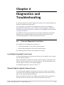
Chapter 4
Diagnostics and
Troubleshooting
This chapter explains the specific diagnostic functions of the HS-RN modules and
provides troubleshooting information.
For a description of the alarm and configuration (“sanity”) error messages
generated by HS-RN module, refer to Appendix B of the Megaplex-2100/2104
Installation and Operation Manual or Chapter 6 of the Megaplex-4100 Installation
and Operation Manual.
The diagnostic information presented in this chapter supplements the general
diagnostics and troubleshooting information instructions contained in the
corresponding Megaplex Installation and Operation Manual.
4.1
Test and Diagnostic Functions
The available test and diagnostics functions are:
•
Local digital loopback on the desired module channel.
•
Remote digital loopback on the desired module channel.
The following sections describe the available test activities.
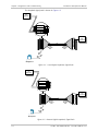
Local Digital Loopback (Local Loop)
The local digital loopback is performed at the input of the digital circuits serving
the corresponding channel.
When the loopback is activated, the channel transmit signal is connected to the
input of the receive path, and is returned to the user's terminal equipment. The
transmit signal is still sent to the remote Megaplex.
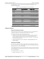
The loopback signal path is shown in Figure 4-1.
Remote Digital Loopback (Remote Loop)
The remote digital loopback is performed at the receive output of the channel
receive path, by connecting the digital signal received from the main link to the
input of the channel digital transmit path.
When the loopback is activated, the digital receive signal remains connected to
the input of the receive path, and is returned toward the remote end.
HS-RN
MP-2100/2104 Ver. 12.6, MP-4100 Ver. 2.0
4-1
Chapter 4 Diagnostics and Troubleshooting
Installation and Operation Manual
The loopback signal path is shown in Figure 4-2.
User or
Test
Equipment
.
.
.
.
.
.
.
.
HS-RN
Local
Megaplex
Unit
Remote
Megaplex
Unit
I/O MODULES
HS-RN
User or
Test
Equipment
System
Management
Figure 4-1. Local Digital Loopback, Signal Path
User or
Test
Equipment
.
.
.
.
.
.
.
.
HS-RN
Local
Megaplex
Unit
Remote
Megaplex
Unit
I/O MODULES
HS-RN
User or
Test
Equipment
System
Management
Figure 4-2. Remote Digital Loopback, Signal Path
4-2
HS-RN
MP-2100/2104 Ver. 12.6, MP-4100 Ver. 2.0
Installation and Operation Manual
4.2
Chapter 4 Diagnostics and Troubleshooting
Troubleshooting
The loops available on the HS-RN module provide a rapid and efficient way to
identify the general location of a fault either of the HS-RN modules connected in
a link, in the external equipment, or in the connections to the channels.
If the LOS indicator of an HS-RN channel lights, or a complaint is received
regarding the transmission of data through one of the HS-RN channels, perform
the following procedure until the problem is located. After each step, continue to
the next step only if the previously specified test has been successfully
completed.
Note
If the problem is detected when a connection between two new users is
activated for the first time, before starting the troubleshooting procedure
described below thoroughly check the timeslot allocation, the configuration of
the two Megaplex units that provide the new connection, and the configuration
of the user's terminal equipment.
•
Request the user to perform a local loopback test on the local data
equipment. If the user equipment does not receive its own signal, the
problem is in the user equipment. After correcting the problem, continue
troubleshooting as explained below.
•
If the signal is not received when the remote digital loopback is activated,
activate the local main link loop on the local Megaplex unit:
If the user equipment does not receive its own signal when the main link
loop is connected, the problem is in the local unit.
If the signal is received when the main link local loopback is activated,
activate the remote main link loop.
If the user equipment does not receive its own signal, the problem is
either in the timeslot allocation, or in the remote unit.
4.3
Q
A
HS-RN
Frequently Asked Questions
When installed in the MP-4100 chassis, do the HS-RN modules operate
exactly the same as when installed in the MP-2100/2104 chassis?
Yes, they do. All the differences between the two module locations are
purely chassis/common logic related (command line vs menu interface,
main link vs CL.1 or I/O ports as timeslot destinations, etc). The main
module-level difference is that the bidirectional broadcast mode (BID-BRD
RX) is not available for the module operating in the Megaplex-4100 chassis.
MP-2100/2104 Ver. 12.6, MP-4100 Ver. 2.0
4-3
Chapter 4 Diagnostics and Troubleshooting
Installation and Operation Manual
Q
Which RS-232 pins are involved in HS-R/HS-RN end-to-end control signals
transfer?
A
HS-R/HS-RN modules support the following end-to-end signals transfer:
4.4
•
DTR to DSR
•
RTS to DCD
Technical Support
Technical support for this product can be obtained from the local distributor from
whom it was purchased.
For further information, please contact the RAD distributor nearest you or one of
RAD's offices worldwide. This information can be found at www.rad.com (offices
– About RAD > Worldwide Offices; distributors – Where to Buy > End Users).
4-4
HS-RN
MP-2100/2104 Ver. 12.6, MP-4100 Ver. 2.0
24 Raoul Wallenberg Street, Tel Aviv 69719, Israel
Tel: +972-3-6458181, Fax +972-3-6483331, +972-3-6498250
E-mail: [email protected], Web site: http://www.rad.com
Customer Response Form
RAD Data Communications would like your help in improving its product documentation.
Please complete and return this form by mail or by fax or send us an e-mail with your
comments.
Thank you for your assistance!
Manual Name:
HS-RN
Publication Number:
764-207-12/08
Please grade the manual according to the following factors:
Excellent
Good
Fair
Poor
Very Poor
Installation instructions
Operating instructions
Manual organization
Illustrations
The manual as a whole
What did you like about the manual?
Error Report
Type of error(s) or
problem(s):
Incompatibility with product
Difficulty in understanding text
Regulatory information (Safety, Compliance, Warnings, etc.)
Difficulty in finding needed information
Missing information
Illogical flow of information
Style (spelling, grammar, references, etc.)
Appearance
Other
Please list the exact page numbers with the error(s), detail the errors you found (information missing,
unclear or inadequately explained, etc.) and attach the page to your fax, if necessary.
Please add any comments or suggestions you may have.
You are:
Who is your distributor?
Your name and company:
Job title:
Address:
Direct telephone number and extension:
Fax number:
E-mail:
Distributor
End user
VAR
Other
Publication No. 764-207-12/08
Order this publication by Catalog No. 803678
International Headquarters
24 Raoul Wallenberg Street
Tel Aviv 69719, Israel
Tel. 972-3-6458181
Fax 972-3-6498250, 6474436
E-mail [email protected]
North America Headquarters
900 Corporate Drive
Mahwah, NJ 07430, USA
Tel. 201-5291100
Toll free 1-800-4447234
Fax 201-5295777
E-mail [email protected]
www.rad.com
The Access Company