1
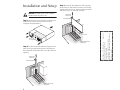
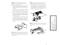
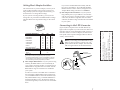
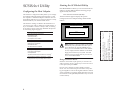
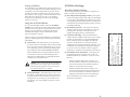
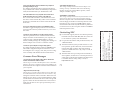
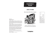
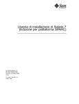
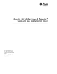
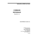
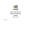
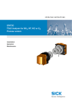
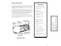
Introduction
Contents
We recommend that you keep this installation guide with your important computer documents. One of the benefits of SCSI is that you can
connect as many as seven peripherals to your host adapter. If you are
not connecting the full complement of seven peripherals during your
initial installation, when the time comes to add another peripheral,
this installation guide will help with that installation.
Also, this installation guide includes information on the Adaptec
SCSISelect™ configuration utility. After installation, you can use this
utility to reconfigure your host adapter without having to reopen the
computer or handle the card.
Installation and Setup
Installation Steps . . . . . . . 2 - 5
Helpful Hints
Using Your Host Adapter . 6
Setting Host Adapter
Switches . . . . . . . . . . . . . . 7
AAAA
AAAA
AA
A
AAAA
AAAAAAAA
AAAAAAAA
AAAAAAAA
AAAAAAA
AAA
AA
A
AA
A
AA
A
AA
A
AA
A
AA
A
AA
A
AA
A
AA
A
AA
A
AA
A
AA
A
AA
A
AA
A
AA
A
AA
A
AA
A
AA
A
AA
A
AA
A
AA
A
AA
A
AA
A
AA
A
AA
A
AA
A
AA
A
AA
A
AA
A
AA
A
AA
A
AA
A
AA
A
AA
A
AA
A
AA
A
AA
A
AA
A
AA
A
AA
A
AA
A
AA
A
AA
A
AA
A
AA
A
AA
A
AA
A
AA
A
AA
A
AA
AAAA
AAAA
AAAA
AAAA
AAAA
AAA
A
AA AAAAAAAAAAAAAAAAAAA
AAAA
A
Connecting to the LED
Connector . . . . . . . . . . . . . 7
AHA-1520B Installation Guide
Part Number: 511162-00, Rev. A
Page 1 of 16
Print Spec Number: 495339-00
Current Date: 5/30/96
Last Modified: May 30, 1996 3:43 pm
File Location: n:\mario\1520b_ig.nec\1520b_ig.frm
ECN Date: 6/11/95
This installation guide provides the instructions needed to install and
use your new SCSI host adapter. Once you have performed the simple
installation steps listed on pages 2 through 5, your host adapter and
SCSI devices are ready for operation.
SCSISelect Utility
Internal SCSI Connector
Switch Block
Connects to the
computer's LED cable
to display activity on
the SCSI bus.
Controls host adapter BIOS
and I/O port addresses in
non-Plug and Play systems.
Configuring the Host
Adapter . . . . . . . . . . . . . . . 8
Starting the SCSISelect
Utility . . . . . . . . . . . . . . . . 8
SCSISelect Settings . . . . . . . 9
1 2 3 4
LED Connector
Uses a 50-pin internal SCSI ribbon cable to
connect internal SCSI devices.
Pin 1
Need Assistance?
Troubleshooting Checklist .11
External SCSI Connector
Uses 50-pin high-density external
Host Adapter BIOS PROM SCSI cables to connect external
Provides booting capabilities
from a SCSI hard disk drive.
Also stores the onboard
SCSISelect configuration utility.
SCSI devices.
Common Problems and
Solutions . . . . . . . . . . . . . .11
Common Error Messages . .13
Contacting NEC . . . . . . . . .13
AHA-1520B Host Adapter
1
Installation and Setup
WARNING: Turn OFF power to the computer
and disconnect the power cord.
Step 3: Insert the host adapter in the slot; press
down firmly so that the bus contacts are securely
seated in the slot. Secure the host adapter bracket
with the screw you removed in Step 2.
Expansion Slot
Bracket Screw
Host Adapter Bracket
Step 1: Remove the cover from the computer case.
(If necessary, refer to the instructions in your
computer documentation.)
Back of
Your Computer
16-bit ISA Expansion Slots
(typically black)
Step 2: Locate an unused 16-bit ISA expansion slot
(this slot is typically black); unscrew and remove
the expansion slot bracket that covers the card-slot
opening.
Expansion Slot
Bracket Screw
Expansion Slot Bracket
16-Bit ISA Expansion Slots
(typically black)
2
AHA-1520B Installation Guide
Part Number: 511162-00, Rev. A
Page 2 of 16
Print Spec Number: 495339-00
Current Date: 5/30/96
Last Modified: May 30, 1996 3:43 pm
File Location: n:\mario\1520b_ig.nec\1520b_ig.frm
ECN Date: 6/11/95
Bus Contacts
AAAA
AAAA
AA
A
AAAA
AAAAAAAA
AAAAAAAA
AAAAAAAA
AAAAAAA
AAA
AA
A
AA
A
AA
A
AA
A
AA
A
AA
A
AA
A
AA
A
AA
A
AA
A
AA
A
AA
A
AA
A
AA
A
AA
A
AA
A
AA
A
AA
A
AA
A
AA
A
AA
A
AA
A
AA
A
AA
A
AA
A
AA
A
AA
A
AA
A
AA
A
AA
A
AA
A
AA
A
AA
A
AA
A
AA
A
AA
A
AA
A
AA
A
AA
A
AA
A
AA
A
AA
A
AA
A
AA
A
AA
A
AA
A
AA
A
AA
A
AA
A
AA
AAAA
AAAA
AAAA
AAAA
AAAA
AAA
A
AA AAAAAAAAAAAAAAAAAAA
AAAA
A
Step 4: Prepare each internal SCSI device for
Step 6: Plug one end of the internal SCSI cable
installation: (If you are installing External SCSI
devices only, skip to Step 10.)
■
Make sure all SCSI devices (internal and external) are
assigned a unique SCSI ID from 0 to 6. Refer to the
device’s documentation for instructions on setting
the SCSI ID.
If you plan to boot your computer from a SCSI hard
disk drive, assign SCSI ID 0 to this drive. If you have a
second hard disk drive, assign SCSI ID 1 to the drive.
■
In Step 7, you will attach one of your internal devices
to the end of the cable. Right now, install (or enable)
terminators on that device. Also, remove (or disable)
terminators on all devices that you plan to install in
the middle of the cable.
On most internal SCSI devices the termination setting
is controlled by setting a jumper or a switch, or by
physically removing or installing a resistor module(s).
Refer to the device’s documentation to determine
how to enable or disable termination on your particular device.
Make sure the colored stripe on one side of the cable
is aligned with pin-1 of the host adapter’s connector.
Pin-1 of the connector is usually designated by a
small triangle (▲), or a “1” on the connector. The host
adapter’s internal connector is also keyed to ensure
the cable is not plugged-in backwards.
Colored
Stripe
50-pin SCSI
Ribbon Cable
Pin 1
Internal SCSI
Connector
Step 7: Plug the other end of the cable into the last
internal device (this device must be terminated, see
Step 4).
Pin 1
Termination
Enabled
Termination
Disabled
Step 5: Install and mount each internal SCSI device
in an available drive bay inside your computer.
(Refer to your computer and device documentation
for instructions.)
Colored Stripe
Internal SCSI
Device
3
AAAA
AAAA
AA
A
AAAA
AAAAAAAA
AAAAAAAA
AAAAAAAA
AAAAAAA
AAA
AA
A
AA
A
AA
A
AA
A
AA
A
AA
A
AA
A
AA
A
AA
A
AA
A
AA
A
AA
A
AA
A
AA
A
AA
A
AA
A
AA
A
AA
A
AA
A
AA
A
AA
A
AA
A
AA
A
AA
A
AA
A
AA
A
AA
A
AA
A
AA
A
AA
A
AA
A
AA
A
AA
A
AA
A
AA
A
AA
A
AA
A
AA
A
AA
A
AA
A
AA
A
AA
A
AA
A
AA
A
AA
A
AA
A
AA
A
AA
A
AA
A
AA
AAAA
AAAA
AAAA
AAAA
AAAA
AAA
A
AA AAAAAAAAAAAAAAAAAAA
AAAA
A
AHA-1520B Installation Guide
Part Number: 511162-00, Rev. A
Page 3 of 16
Print Spec Number: 495339-00
Current Date: 5/30/96
Last Modified: May 30, 1996 3:43 pm
File Location: n:\mario\1520b_ig.nec\1520b_ig.frm
ECN Date: 6/11/95
■
into the host adapter’s internal SCSI connector.
Step 8: Plug the remaining connectors on the cable
into any remaining internal devices (these devices
must not be terminated, see Step 4).
Pin 1
Colored Stripe
■
In Steps 11 and 12, you will be attaching one of your
external devices to the end of the daisy-chain. Right
now, install (or enable) terminators on that device.
Also, remove (or disable) terminators on all devices
that you plan to attach in the middle.
On most external SCSI devices, termination is controlled by installing or removing a terminating plug
(see Step 11). Refer to the device’s documentation to
determine how to enable or disable termination on
your particular device.
To Host
Adapter
To 1st Internal
SCSI Device
Step 9: Connect an available DC power cable
(from your computer’s power supply) to the power
input connector on the SCSI device.
Power Input Connector on
the Back of the Drive
Termination
Enabled
Termination
Disabled
Termination
Disabled
Step 11: Plug one end of the external SCSI cable
into the host adapter’s external SCSI connector and
plug the other end of the cable into either one of the
SCSI connectors on the external SCSI device. (If you
are installing only one external device, attach a
terminating plug to the device.)
DC Power Cable
(from the Power Supply)
Step 10: Prepare each external SCSI device for
installation: (If you are not installing external SCSI
devices, skip to Step 13.)
■
Make sure all SCSI devices (external and internal) are
assigned a unique SCSI ID from 0 to 6. Refer to the
device’s documentation for instructions on setting
the SCSI ID.
If you plan to boot your computer from a SCSI hard
disk drive, assign SCSI ID 0 to this drive. If you have a
second hard disk drive, assign SCSI ID 1 to the drive.
3
Terminating Plug
4
AAAA
AAAA
AA
A
AAAA
AAAAAAAA
AAAAAAAA
AAAAAAAA
AAAAAAA
AAA
AA
A
AA
A
AA
A
AA
A
AA
A
AA
A
AA
A
AA
A
AA
A
AA
A
AA
A
AA
A
AA
A
AA
A
AA
A
AA
A
AA
A
AA
A
AA
A
AA
A
AA
A
AA
A
AA
A
AA
A
AA
A
AA
A
AA
A
AA
A
AA
A
AA
A
AA
A
AA
A
AA
A
AA
A
AA
A
AA
A
AA
A
AA
A
AA
A
AA
A
AA
A
AA
A
AA
A
AA
A
AA
A
AA
A
AA
A
AA
A
AA
A
AA
AAAA
AAAA
AAAA
AAAA
AAAA
AAA
A
AA AAAAAAAAAAAAAAAAAAA
AAAA
A
AHA-1520B Installation Guide
Part Number: 511162-00, Rev. A
Page 4 of 16
Print Spec Number: 495339-00
Current Date: 5/30/96
Last Modified: May 30, 1996 3:43 pm
File Location: n:\mario\1520b_ig.nec\1520b_ig.frm
ECN Date: 6/11/95
2nd Internal SCSI
Device
■
daisy-chaining each device to the previous device
until all external SCSI devices have been connected.
(The device at the end of the chain must have a
terminating plug installed.)
■
Windows® 95: Windows 95 has embedded driver
support for your host adapter. When you start
Windows 95, the host adapter is detected and the
appropriate driver is automatically installed. To take
advantage of various productivity tools and accessories, you should also install Adaptec EZ-SCSI software. See the EZ-SCSI software documentation for
installation instructions.
NetWare, OS/2, Windows NT™, and UNIX: The
most current versions of these operating systems
have embedded driver support for your host adapter
as part of their installation software. For instructions
on installing embedded driver support, see the operating system documentation.
Congratulations! Installation of your host
2
3
4
Terminating Plug
Step 13: Reinstall your computer cover and
connect all power cables; turn ON your computer:
adapter is complete. For useful information on
using your host adapter, refer to Helpful Hints on
page 6. For instructions on using the SCSISelect
configuration utility, refer to SCSISelect Utility on
page 8. If you need further help, refer to Need Assistance? on page 11.
Step 14: Install the appropriate host adapter
software driver for your operating system:
■
DOS and Windows ® 3.x: Because drivers for DOS
and Windows 3.x are not embedded in the operating
system, you must load them yourself. If your host
adapter came bundled with Adaptec EZ-SCSI® software, see the EZ-SCSI software documentation for
installation instructions. If you wish to purchase
EZ-SCSI, you can call Adaptec to order directly.
If you purchased your host adapter as part of a bundle created by a third party, you can use the drivers
they provide. Please refer to the documentation provided by the third party or contact them directly for
installation instructions.
5
AAAA
AAAA
AA
A
AAAA
AAAAAAAA
AAAAAAAA
AAAAAAAA
AAAAAAA
AAA
AA
A
AA
A
AA
A
AA
A
AA
A
AA
A
AA
A
AA
A
AA
A
AA
A
AA
A
AA
A
AA
A
AA
A
AA
A
AA
A
AA
A
AA
A
AA
A
AA
A
AA
A
AA
A
AA
A
AA
A
AA
A
AA
A
AA
A
AA
A
AA
A
AA
A
AA
A
AA
A
AA
A
AA
A
AA
A
AA
A
AA
A
AA
A
AA
A
AA
A
AA
A
AA
A
AA
A
AA
A
AA
A
AA
A
AA
A
AA
A
AA
A
AA
AAAA
AAAA
AAAA
AAAA
AAAA
AAA
A
AA AAAAAAAAAAAAAAAAAAA
AAAA
A
AHA-1520B Installation Guide
Part Number: 511162-00, Rev. A
Page 5 of 16
Print Spec Number: 495339-00
Current Date: 5/30/96
Last Modified: May 30, 1996 3:43 pm
File Location: n:\mario\1520b_ig.nec\1520b_ig.frm
ECN Date: 6/11/95
Step 12: Connect other external SCSI devices by
Hard Disk Drives
■
Using Your Host Adapter
■
You may need to install the manufacturer’s proprietary device drivers if you use SCSI devices other than
hard disk drives and CD-ROM drives. (See your
device’s documentation.)
■
For all SCSI devices connected to the host adapter,
make sure to use high-quality SCSI cables to ensure
reliable data transfer.
■
When one or more Fast SCSI devices are connected to
the host adapter, the combined length of all cables
(internal and external) must not exceed 3 meters
(9.8 feet) to ensure reliable operation. If no Fast SCSI
devices are connected, the combined length of all
cables must not exceed 6 meters (19.7 feet). See your
device’s documentation to determine if it is a Fast
SCSI device.
■
6
Your host adapter can support the SCSI Configured
AutoMatically (SCAM) protocol, which assigns SCSI
IDs dynamically and resolves SCSI ID conflicts automatically at bootup. To enable or disable SCAM support, see Advanced Host Adapter Settings on page 10. If
your system includes SCSI disk drives or other
devices that support SCAM, when SCAM is enabled
you do not need to manually assign SCSI IDs to these
devices. Most SCSI devices currently in use, however,
do not support SCAM and must have their SCSI IDs
set manually.
Every hard disk must be physically low-level formatted, partitioned, and logically formatted before it can
be used to store data. SCSI hard disks are physically
formatted at the factory and do not need to be physically formatted again.
If you connected a new hard disk drive to your host
adapter, you must partition and logically format the
drive. For DOS and Windows (3.x and 95) use the
DOS Fdisk and Format commands (see your computer and DOS documentation). For other operating
systems, see your operating system documentation.
■
■
If you are booting from a SCSI hard disk drive, make
sure the Hard Disk (or Drives) setting in your
computer’s CMOS setup program is set to None or
No Drives Installed, as is required for SCSI hard disk
drives. (See your computer documentation.)
If both SCSI and non-SCSI (e.g., IDE) disk drives are
installed, then the non-SCSI disk drive is always the
boot device.
Multiple Host Adapters
■
Multiple SCSI host adapters can be installed in your
computer; you are limited only by the available system resources (e.g., I/O port and BIOS addresses).
■
Each host adapter you install forms a separate SCSI
bus with a different set of SCSI devices. SCSI IDs can
be reused as long as the ID is assigned to a device on
a different host adapter (e.g., each host adapter can
have a device with SCSI ID 0).
■
If you have two or more SCSI host adapters, enable
the BIOS only on the boot host adapter; disable the
BIOS on the remaining host adapters.
AAAA
AAAA
AA
A
AAAA
AAAAAAAA
AAAAAAAA
AAAAAAAA
AAAAAAA
AAA
AA
A
AA
A
AA
A
AA
A
AA
A
AA
A
AA
A
AA
A
AA
A
AA
A
AA
A
AA
A
AA
A
AA
A
AA
A
AA
A
AA
A
AA
A
AA
A
AA
A
AA
A
AA
A
AA
A
AA
A
AA
A
AA
A
AA
A
AA
A
AA
A
AA
A
AA
A
AA
A
AA
A
AA
A
AA
A
AA
A
AA
A
AA
A
AA
A
AA
A
AA
A
AA
A
AA
A
AA
A
AA
A
AA
A
AA
A
AA
A
AA
A
AA
AAAA
AAAA
AAAA
AAAA
AAAA
AAA
A
AA AAAAAAAAAAAAAAAAAAA
AAAA
A
AHA-1520B Installation Guide
Part Number: 511162-00, Rev. A
Page 6 of 16
Print Spec Number: 495339-00
Current Date: 5/30/96
Last Modified: May 30, 1996 3:43 pm
File Location: n:\mario\1520b_ig.nec\1520b_ig.frm
ECN Date: 6/11/95
Helpful Hints
Setting Host Adapter Switches
The switch block on your host adapter, is factory set to
work in a Plug and Play system. Since resources in a
Plug and Play system are assigned automatically, you
should not have to change these settings.
If your system is not Plug and Play, you may have to
change the I/O port address and BIOS address settings.
The table below lists all possible settings on the switch
block.
■
Host Adapter I/O Port Address—If your system is
Plug and Play, the I/O port address is set automatically. If your system is not Plug and Play, you should
choose an I/O address range that does not conflict
with the I/O address range of another device installed
in your system.
4
1 2 3
Connecting to the LED Connector
sw1
Off
On
Off
On
Off
On
Off
On
sw2
Off
Off
On
On
Off
Off
On
On
sw4
Off
On
sw3
Off
Off
Off
Off
On
On
On
On
(Optional) Most computers have an LED disk activity
light on the front panel. If you disconnect the cable from
the LED connector on the motherboard and connect it to
the LED connector on the host adapter, the LED on the
front panel of the computer will light whenever there is
activity on the SCSI bus.
Note: If you are using non-SCSI disk drives (e.g.,
IDE), you may not want to connect your computer’s LED to the host adapter, since the LED
will no longer indicate non-SCSI disk activity.
LED Cable
from Motherboard
(Open = Off)
1 Do not use this setting in Legacy/Non-Plug and Play systems.
2 If you disable the BIOS PROM, you must run SCSISelect to synchronize
the host adapter’s resource table with your new selection. Synchronization is automatically performed just by entering SCSISelect.
■
Host Adapter BIOS Address—If your system is Plug
and Play, the BIOS address is set automatically. If
your system is not Plug and Play, you should choose
a BIOS address range that does not conflict with the
BIOS address range of another device installed in
your system.
2-pin
LED
Cable
1
Pin 1
LED Connector
on Host Adapter
In order to boot from a SCSI disk drive connected to
the host adapter, a BIOS address must be selected. If
you set the BIOS address to BIOS PROM Disabled (set
sw1, sw2 and sw3 to On), you disable all BIOS functionality (including access to the SCSISelect utility at
system bootup) and you cannot boot from a SCSI disk
drive.
7
AAAA
AAAA
AA
A
AAAA
AAAAAAAA
AAAAAAAA
AAAAAAAA
AAAAAAA
AAA
AA
A
AA
A
AA
A
AA
A
AA
A
AA
A
AA
A
AA
A
AA
A
AA
A
AA
A
AA
A
AA
A
AA
A
AA
A
AA
A
AA
A
AA
A
AA
A
AA
A
AA
A
AA
A
AA
A
AA
A
AA
A
AA
A
AA
A
AA
A
AA
A
AA
A
AA
A
AA
A
AA
A
AA
A
AA
A
AA
A
AA
A
AA
A
AA
A
AA
A
AA
A
AA
A
AA
A
AA
A
AA
A
AA
A
AA
A
AA
A
AA
A
AA
AAAA
AAAA
AAAA
AAAA
AAAA
AAA
A
AA AAAAAAAAAAAAAAAAAAA
AAAA
A
AHA-1520B Installation Guide
Part Number: 511162-00, Rev. A
Page 7 of 16
Print Spec Number: 495339-00
Current Date: 5/30/96
Last Modified: May 30, 1996 3:43 pm
File Location: n:\mario\1520b_ig.nec\1520b_ig.frm
ECN Date: 6/11/95
OPEN
Host Adapter BIOS Address
DC000-DFFFF
D8000-DBFFF
D4000-D7FFF
D0000-D3FFF
CC000-CFFFF
C8000-CBFFF
Inactive1
BIOS PROM Disabled2
Host Adapter I/O Port Address
340-35F
140-15F
If you wish to disable BIOS functionality and still
have access to SCSISelect, do not disable the BIOS
PROM with the switches. Instead, change the Host
Adapter BIOS setting in SCSISelect to Disabled.
Configuring the Host Adapter
The SCSISelect configuration utility allows you to change
host adapter and SCSI settings without having to open
the computer or handle the adapter. SCSISelect also contains utilities that allow you to low-level format or verify
the disk media of your SCSI hard disk drives.
The SCSISelect settings are listed in the table below. If
you want to view and/or change the current settings, or
if you would like to format or verify a disk, see Starting
the SCSISelect Utility on this page. Detailed descriptions
of each setting begin on page 9.
Basic Host Adapter Settings
Host Adapter Interrupt (IRQ) Channel
Host Adapter SCSI ID
SCSI Parity Checking
Host Adapter SCSI Termination
SCSI Device Settings
Initiate Sync Negotiation
Maximum Sync Transfer Rate
Enable Disconnection
Send Start Unit SCSI Command1
Advanced Host Adapter Settings
ISA Plug and Play Support
Plug and Play SCAM Support
Host Adapter BIOS
Support Removable Disks Under BIOS as Fixed Disks1
Extended BIOS Translation for DOS Drives > 1 GByte1
1
Starting the SCSISelect Utility
If the BIOS PROM is enabled, you can start the SCSISelect
utility by pressing Ctrl-A when the following prompt
appears briefly at boot time:
Press <Ctrl><A> for SCSISelect (TM) Utility!
The first menu that appears displays the options
Configure/View Host Adapter Settings and SCSI Disk
Utilities.
Adaptec AHA-1520B/1522B
SCSISelect(TM)
Utility v1.11
AHA-1520B/1522B at Port 0340h
Would you like to configure the host adapter or run the
SCSI disk utilities? Select the option and press <Enter>.
Press <F5> to switch between color and monochrome modes.
Options
Configure/View Host Adapter Settings
SCSI Disk Utilities
Arrow keys to move cursor, <Enter> to select option, <Esc> to exit (* =default)
Note: SCSISelect is also provided on a bootable
diskette. If your system does not allow you to
access SCSISelect by pressing Ctrl-A at boot
time, you can run SCSISelect from this diskette.
To run, simply insert the diskette in a bootable
floppy drive and boot your system. Save this
diskette. You may need it later if you ever lose
access to the BIOS PROM.
Settings take effect only if Host Adapter BIOS is enabled.
Using SCSISelect Menus
SCSISelect uses menus to list options you can select. To
select an option, use the ↑ and ↓ keys to move the cursor
to the option, then press Enter.
In some cases, selecting an option displays another
menu. You can return to the previous menu at any time
by pressing Esc. To restore the original SCSISelect default
values, press F6. To toggle the display between color and
monochrome modes, press F5 (this feature may not work
on all monitors).
8
AAAA
AAAA
AA
A
AAAA
AAAAAAAA
AAAAAAAA
AAAAAAAA
AAAAAAA
AAA
AA
A
AA
A
AA
A
AA
A
AA
A
AA
A
AA
A
AA
A
AA
A
AA
A
AA
A
AA
A
AA
A
AA
A
AA
A
AA
A
AA
A
AA
A
AA
A
AA
A
AA
A
AA
A
AA
A
AA
A
AA
A
AA
A
AA
A
AA
A
AA
A
AA
A
AA
A
AA
A
AA
A
AA
A
AA
A
AA
A
AA
A
AA
A
AA
A
AA
A
AA
A
AA
A
AA
A
AA
A
AA
A
AA
A
AA
A
AA
A
AA
A
AA
AAAA
AAAA
AAAA
AAAA
AAAA
AAA
A
AA AAAAAAAAAAAAAAAAAAA
AAAA
A
AHA-1520B Installation Guide
Part Number: 511162-00, Rev. A
Page 8 of 16
Print Spec Number: 495339-00
Current Date: 5/30/96
Last Modified: May 30, 1996 3:43 pm
File Location: n:\mario\1520b_ig.nec\1520b_ig.frm
ECN Date: 6/11/95
SCSISelect Utility
To exit SCSISelect, press Esc until a message prompts you
to exit (if you changed any host adapter settings, you are
prompted to save the changes before you exit). At the
prompt, select Yes to exit, then press any key to reboot
the computer. Any changes you made in SCSISelect take
effect after the computer boots. (If you are running
SCSISelect from the floppy, be sure to eject the floppy
before you re-boot.)
SCSISelect Settings
Basic Host Adapter Settings
The following settings are the SCSISelect settings most
likely to require any modification.
■
Host Adapter Interrupt (IRQ) Channel—This option
sets the host adapter’s IRQ. Each add-in card installed
in your system, including the host adapter, must have
a unique IRQ. In Plug and Play systems, the IRQ is set
automatically. In non-Plug and Play systems you must
set the IRQ manually.
■
Host Adapter SCSI ID— This option sets the host
adapter’s SCSI ID. We recommend that you set the
host adapter to SCSI ID 7, which gives the host
adapter the highest priority on the SCSI bus.
■
SCSI Parity Checking—This option determines
whether the host adapter verifies the accuracy of data
transfer on the SCSI bus. You should disable SCSI
Parity Checking on the host adapter and all SCSI
devices if any SCSI device connected to the host
adapter does not support SCSI parity; otherwise, set it
to Enabled. Most SCSI devices do support SCSI parity. If you are not sure whether a device supports
SCSI parity, consult the documentation for the device.
■
Host Adapter SCSI Termination—This option sets
termination on the host adapter. You can set it to
Enabled, Disabled, or Automatic. Automatic works
like this:
Using the SCSI Disk Utilities
To access the SCSI disk utilities, select the SCSI Disk
Utilities option from the menu that appears after starting
SCSISelect. Once the option is selected, SCSISelect immediately scans the SCSI bus (to determine the devices
installed) and displays a list of all SCSI IDs and the
devices assigned to each ID.
When you select a specific ID and device, a small menu
appears, displaying the options Format Disk and Verify
Disk Media.
■
Format Disk—This utility allows you to perform a
low-level format on a hard disk drive. Each hard disk
drive must be low-level formatted before you can use
your operating system’s partitioning and file preparation utilities, such as MS-DOS fdisk and format.
Most SCSI disk devices are preformatted at the factory and do not need to be formatted again. The
Adaptec Format Disk utility is compatible with the
vast majority of SCSI disk drives.
–
If the host adapter detects that a cable is connected to either its internal or external SCSI connector, then it enables its terminators (the host
adapter is at the end of the SCSI bus).
–
If the host adapter detects that a cable is connected to both its internal and external SCSI connector, then it disables its terminators (the host
adapter lies between the ends of the SCSI bus).
Caution: A low-level format destroys all data on
the drive. Be sure to back up your data before
performing this operation. You cannot abort a
low-level format once it is started.
■
Verify Disk Media—This utility allows you to scan
the media of a hard disk drive for defects. If the utility finds bad blocks on the media, it prompts you to
reassign them; if you select yes, those blocks are no
longer used. You can press Esc at any time to abort
the utility.
We recommend that you set the host adapter to
Automatic termination.
9
AAAA
AAAA
AA
A
AAAA
AAAAAAAA
AAAAAAAA
AAAAAAAA
AAAAAAA
AAA
AA
A
AA
A
AA
A
AA
A
AA
A
AA
A
AA
A
AA
A
AA
A
AA
A
AA
A
AA
A
AA
A
AA
A
AA
A
AA
A
AA
A
AA
A
AA
A
AA
A
AA
A
AA
A
AA
A
AA
A
AA
A
AA
A
AA
A
AA
A
AA
A
AA
A
AA
A
AA
A
AA
A
AA
A
AA
A
AA
A
AA
A
AA
A
AA
A
AA
A
AA
A
AA
A
AA
A
AA
A
AA
A
AA
A
AA
A
AA
A
AA
A
AA
AAAA
AAAA
AAAA
AAAA
AAAA
AAA
A
AA AAAAAAAAAAAAAAAAAAA
AAAA
A
AHA-1520B Installation Guide
Part Number: 511162-00, Rev. A
Page 9 of 16
Print Spec Number: 495339-00
Current Date: 5/30/96
Last Modified: May 30, 1996 3:43 pm
File Location: n:\mario\1520b_ig.nec\1520b_ig.frm
ECN Date: 6/11/95
Exiting SCSISelect
■
Plug and Play SCAM Support—This option determines whether the host adapter automatically assigns
SCSI IDs to SCSI devices that support the SCAM protocol (see Using Your Host Adapter on page 6). Most
non-SCAM devices tolerate the SCAM protocol, so
you can enable this option even if you have a nonSCAM device.
■
Host Adapter BIOS—This option enables or disables
the host adapter BIOS functionality. Unlike the DIP
switch BIOS PROM Disabled setting, when you disable the Host Adapter BIOS with SCSISelect, you still
have access to SCSISelect. If you are booting from a
SCSI disk drive connected to the host adapter, the
BIOS must be enabled.
The SCSI device settings allow you to configure certain
parameters for each device on the SCSI bus. To configure
settings for a specific device, you must know the SCSI ID
assigned to that device. If you are not sure of the SCSI ID,
see Using the SCSI Disk Utilities on page 9.
■
■
■
■
Initiate Sync Negotiation—This option determines
whether synchronous data transfer negotiation (Sync
Negotiation) between the device and host adapter is
initiated by the host adapter. Normally, the Initiate
Sync Negotiation setting should be enabled, because
most SCSI devices support synchronous negotiation
and because it allows for faster data transfer.
Maximum Sync Transfer Rate—This option sets the
maximum synchronous data transfer rate that the
host adapter supports. The host adapter supports
rates up to the Fast SCSI maximum of 10.0 MBytes/
sec. In most cases, you can use the maximum value of
10.0.
Enable Disconnection—This option determines
whether the host adapter allows the SCSI device to
disconnect from the SCSI bus (sometimes called
Disconnect/Reconnect). If you have only one device
on the SCSI bus, disabling disconnection will give a
slight performance increase. If you have more than
one device on the SCSI bus, disconnection should be
enabled to allow multithreaded SCSI operation.
Send Start Unit Command—This option determines
whether the Start Unit Command is sent to the SCSI
device at bootup. Most devices do not require this,
but check your device’s documentation.
Advanced Host Adapter Settings
The advanced host adapter settings should not be
changed unless absolutely necessary.
■
10
ISA Plug and Play Support—This option determines
whether the host adapter supports Plug and Play
functionality. When Plug and Play Support is
enabled, the host adapter will work fine in both Plug
and Play and Legacy (non-Plug and Play) systems.
The only time you should disable Plug and Play Support is when you have an “ill-behaved” Plug and
Play system. If you cannot get your host adapter
working in a Plug and Play system, as a last resort,
try disabling this setting.
Several SCSISelect options are not valid unless the
host adapter BIOS is enabled. The table on page 8
identifies these options. You should disable the host
adapter BIOS if the peripherals on the SCSI bus (for
example, CD-ROM drives) are all controlled by
device drivers and do not need the BIOS.
■
Support Removable Disks Under BIOS as Fixed
Disks—This option controls which removable-media
drives are supported by the host adapter BIOS. The
following choices are available:
–
Boot Only—Only the removable-media drive
designated as the boot device is treated as a hard
disk drive.
–
All Disks—All removable-media drives supported by the BIOS are treated as hard disk drives.
–
Disabled— No removable-media drives are
treated as hard disk drives. In this situation, software drivers are needed because the drives are
not controlled by the BIOS.
Caution: If a removable-media SCSI device is
controlled by the host adapter BIOS, do not
remove the media while the drive is on or you
may lose data! If you want to be able to remove
media while the drive is on, install the removable-media device driver and set this option to
Disabled.
AAAA
AAAA
AA
A
AAAA
AAAAAAAA
AAAAAAAA
AAAAAAAA
AAAAAAA
AAA
AA
A
AA
A
AA
A
AA
A
AA
A
AA
A
AA
A
AA
A
AA
A
AA
A
AA
A
AA
A
AA
A
AA
A
AA
A
AA
A
AA
A
AA
A
AA
A
AA
A
AA
A
AA
A
AA
A
AA
A
AA
A
AA
A
AA
A
AA
A
AA
A
AA
A
AA
A
AA
A
AA
A
AA
A
AA
A
AA
A
AA
A
AA
A
AA
A
AA
A
AA
A
AA
A
AA
A
AA
A
AA
A
AA
A
AA
A
AA
A
AA
A
AA
AAAA
AAAA
AAAA
AAAA
AAAA
AAA
A
AA AAAAAAAAAAAAAAAAAAA
AAAA
A
AHA-1520B Installation Guide
Part Number: 511162-00, Rev. A
Page 10 of 16
Print Spec Number: 495339-00
Current Date: 5/30/96
Last Modified: May 30, 1996 3:43 pm
File Location: n:\mario\1520b_ig.nec\1520b_ig.frm
ECN Date: 6/11/95
SCSI Device Settings
Extended BIOS Translation for DOS Drives
> 1 GByte—This option determines whether extended
translation is available for SCSI hard disks with capacities greater than 1 GByte. Extended BIOS Translation
is used only with MS-DOS 5.0 or above. You do not
need to enable this option if you are using another
operating system such as NetWare or UNIX.
Caution: If you decide to change the translation
scheme, back up your disk drives first! All data
is erased when you change from one translation
scheme to another.
The standard translation scheme for SCSI host
adapters provides a maximum accessible capacity of
1 GByte. To support disk drives larger than 1 GByte,
the AHA-1520B includes an extended translation
scheme. This scheme, under MS-DOS, supports 2
GBytes partitions on disk drives as large as 8 GBytes.
When you partition a disk under BIOS control larger
than 1 GByte, use the MS-DOS fdisk utility as you
normally would. (Because the cylinder size increases
to 8 MBytes under extended translation, the partition
size you choose must be a multiple of 8 MBytes. If
you request a size that is not a multiple of 8 MBytes,
fdisk rounds up to the nearest whole multiple of 8
MBytes.)
Need Assistance?
Troubleshooting Checklist
Most problems that occur with your host adapter result
from errors in preparing and connecting devices on the
SCSI bus. If you have problems when using your host
adapter, check these items first.
■
Are all SCSI devices powered?
■
Are all SCSI bus cables and power cables properly
connected?
■
Is the host adapter firmly seated and secured in an
expansion slot?
■
Is pin-1 orientation maintained throughout the SCSI
bus? (See Step 6 on page 3.)
■
Do the host adapter and all devices on the SCSI bus
have unique SCSI IDs? (See Step 4 on page 3, and
Step 10 on page 4.)
■
Are all devices on the SCSI bus terminated properly?
(See Step 4 on page 3, and Step 10 on page 4.)
■
Is parity checking consistently enabled or disabled on
all devices (including the host adapter) on the SCSI
bus? (See Basic Host Adapter Settings on page 9.)
If you still have problems after checking the above items,
continue with the following sections.
Common Problems and Solutions
When the Adaptec BIOS header message appears, it hangs my system.
Make sure the SCSI hard drives at SCSI ID 0 and 1 are
properly terminated. Check for possible resource conflicts between the host adapter and other cards installed
in your computer; the cards may have conflicting BIOS
address, I/O port address, DMA channel, and IRQ settings. Make sure Shadow RAM is not enabled in your
computer’s CMOS setup program.
11
AAAA
AAAA
AA
A
AAAA
AAAAAAAA
AAAAAAAA
AAAAAAAA
AAAAAAA
AAA
AA
A
AA
A
AA
A
AA
A
AA
A
AA
A
AA
A
AA
A
AA
A
AA
A
AA
A
AA
A
AA
A
AA
A
AA
A
AA
A
AA
A
AA
A
AA
A
AA
A
AA
A
AA
A
AA
A
AA
A
AA
A
AA
A
AA
A
AA
A
AA
A
AA
A
AA
A
AA
A
AA
A
AA
A
AA
A
AA
A
AA
A
AA
A
AA
A
AA
A
AA
A
AA
A
AA
A
AA
A
AA
A
AA
A
AA
A
AA
A
AA
A
AA
AAAA
AAAA
AAAA
AAAA
AAAA
AAA
A
AA AAAAAAAAAAAAAAAAAAA
AAAA
A
AHA-1520B Installation Guide
Part Number: 511162-00, Rev. A
Page 11 of 16
Print Spec Number: 495339-00
Current Date: 5/30/96
Last Modified: May 30, 1996 3:43 pm
File Location: n:\mario\1520b_ig.nec\1520b_ig.frm
ECN Date: 6/11/95
■
If both SCSI and non-SCSI (e.g., IDE) disk drives are
installed, then the non-SCSI disk drive is always the boot
device. If your system has only SCSI disk drives:
■
Make sure the host adapter BIOS is enabled through
the switch block and in SCSISelect.
■
Make sure the Hard Disk (or Drives) setting in your
computer’s setup program is set to None or No
Drives Installed, as is required for SCSI hard disk
drives.
■
Make sure the SCSI boot drive is set to SCSI ID 0. If
you have a second SCSI disk drive, assign SCSI ID 1
to the drive.
When trying to run the format/verify SCSI disk utility in SCSISelect, I
get an Unexpected SCSI Command Failure pop-up box with error
information.
The utility probably encountered a problem with the disk
device or the media and therefore cannot run. You can
determine from the Sense Key information (e.g., 06h Unit Attention) both the cause of the problem and its
solution. Here are some of the more common Sense Key
values and their meanings:
■
02h - Not ready—The media is not ready to format.
Be sure that media is inserted in the drive and that
the media is spun up.
■
03h - Medium error—The disk media may be defective. If it is a removable-media drive, try using a different disk media. If it is a fixed disk drive, the disk
may be physically damaged. Verify and format the
media with SCSISelect.
The system works erratically. It hangs or the host adapter sometimes
cannot find the drives.
Check cable length and integrity. If one or more Fast SCSI
devices are installed, the total length of all cables (internal and external) connected to the host adapter should
not exceed 3 meters (9.8 feet). If no Fast SCSI devices are
connected, the total length of all cables should not exceed
6 meters (19.7 feet).
When trying to install SCO UNIX, I get an F12 error message; or, SCO
UNIX will not boot up after being installed.
Run SCSISelect and disable Plug and Play Support, Plug
and Play SCAM Support, and Extended BIOS Translation
for DOS Drives > 1 GByte.
Note: If a partition was created using the above
settings enabled you may need to low level format the hard drive and reinstall SCO UNIX;
make sure to disable the settings listed above.
I have both a Soundblaster card with a SCSI controller embedded on
it, and an AHA-1520B installed in the same computer. Am I going to
experience any resource conflicts?
The AHA-1520B and the SCSI controller on the Soundblaster card are typically both set, by default, to use I/O
port address 340 and IRQ 11. In addition, the Soundblaster card may also use I/O port address 330 for its
Midi port. To avoid resource conflicts, make sure to
change the settings on one of the cards.
12
■
04h - Hardware error—The disk drive may be defective. Consult the hardware documentation and contact the manufacturer.
■
05h - Illegal request—The Adaptec formatting utility
does not support a low-level format of this device;
however, the device may already be low-level formatted by the manufacturer. (This error rarely occurs.)
■
06h - Unit attention—The removable media may be
write-protected. Disable write protection and run the
utility again.
I disabled the host adapter BIOS via the switch block, and now I can
no longer run SCSISelect to configure the host adapter.
Once the BIOS is disabled via the switch block, you can
no longer access SCSISelect. To disable the BIOS and still
have access to SCSISelect, complete the following:
1 Set the Host Adapter BIOS Address setting on the
switch block to an available BIOS address (see Setting
Host Adapter Switches on page 7).
2 Run the SCSISelect utility, disable the Host Adapter
BIOS setting in Advanced Configuration Options (this
disables the BIOS but still allows access to SCSISelect).
See Starting the SCSISelect Utility on page 8.
AAAA
AAAA
AA
A
AAAA
AAAAAAAA
AAAAAAAA
AAAAAAAA
AAAAAAA
AAA
AA
A
AA
A
AA
A
AA
A
AA
A
AA
A
AA
A
AA
A
AA
A
AA
A
AA
A
AA
A
AA
A
AA
A
AA
A
AA
A
AA
A
AA
A
AA
A
AA
A
AA
A
AA
A
AA
A
AA
A
AA
A
AA
A
AA
A
AA
A
AA
A
AA
A
AA
A
AA
A
AA
A
AA
A
AA
A
AA
A
AA
A
AA
A
AA
A
AA
A
AA
A
AA
A
AA
A
AA
A
AA
A
AA
A
AA
A
AA
A
AA
A
AA
AAAA
AAAA
AAAA
AAAA
AAAA
AAA
A
AA AAAAAAAAAAAAAAAAAAA
AAAA
A
AHA-1520B Installation Guide
Part Number: 511162-00, Rev. A
Page 12 of 16
Print Spec Number: 495339-00
Current Date: 5/30/96
Last Modified: May 30, 1996 3:43 pm
File Location: n:\mario\1520b_ig.nec\1520b_ig.frm
ECN Date: 6/11/95
I installed the host adapter and my SCSI disk drive, but my computer
will not boot from the SCSI disk drive.
Try changing the following device settings in SCSISelect
for your older SCSI-1 device: Set Initiate Sync Negotiation
to No; Set the Maximum Sync Transfer Rate to 5.0.
One of the SCSI devices on my computer does not allow me to
disable termination. How can I install it on the SCSI bus?
If it is an external SCSI device, install the device as the
last device of the external daisy chain. If it is an internal
SCSI device, install the device at the end of the internal
SCSI cable.
The screen is difficult to read when I run the SCSISelect utility.
Press F5 to toggle the display between color and monochrome modes. This may make it easier for you to read
the screen.
I cannot use my host adapter in a non-Plug and Play system.
Check for possible resource conflicts between the host
adapter and other cards installed in your computer; the
cards may have conflicting BIOS address, I/O port
address, and IRQ settings. Try changing these settings on
the host adapter one at a time to isolate the conflict.
“Host Adapter diagnostic error!”
This message usually indicates that the host adapter is not
working correctly—Check the items in Troubleshooting
Checklist on page 11. If the problems persists, contact
Adaptec customer support.
“No ROM Basic, system halted”
This message usually indicates that the first hard drive in the
system has not been set as the active or bootable partition—
Start the computer with a bootable diskette. Run Fdisk
from the floppy and make sure that the partition on the
hard drive is set to Active. (Use Fdisk and the option
Show Partition Information.) If the hard drive partition is
not shown as active, then use option number 2 of Fdisk to
make the partition active.
Contacting NEC
■
For technical support (answers to technical questions,
information about the NEC BBS, Web site, and access
to our FastFacts system) call 1-800-632-4667.
■
For pre-sales information and product literature, call
1-800-NEC-INFO.
■
The NEC FastFacts system provides answers to common questions, product literature, and current information about NEC products. The NEC FastFacts
system is available 24 hours a day, 7 days a week, at
1-800-366-0476.
■
The NEC Web server provides product information,
driver updates, and answers to common questions, as
well as direct ordering through NEC. The NEC server
is available 24 hours a day, 7 days a week, at
http://www.nec.com.
I cannot use my host adapter in a Plug and Play System
Try setting ISA Plug and Play Support to Disable in the
Advanced Configuration Options of SCSISelect. Your
host adapter is now a Legacy card, and you must configure it manually with the DIP switches and SCSISelect.
Common Error Messages
“Can not locate any host adapter at either 340h or 140h IO Port
address. Possible IO Port address conflict”
This message occurs when the BIOS fails to locate a valid host
adapter in the system—Check for an I/O port address conflict between the host adapter and other cards installed in
your computer.
❒
“Target connected, but not ready”
This message occurs when the host adapter requests data from
an installed SCSI device and does not receive an answer—Try
setting the Send Start Unit Command to Yes for the host
adapter. If your device is a removable-media drive, make
sure the media is inserted in the drive. If the message still
appears, follow the drive manufacturer’s instructions to
make sure the drive is set to spin up when the power is
switched ON.
13
AAAA
AAAA
AA
A
AAAA
AAAAAAAA
AAAAAAAA
AAAAAAAA
AAAAAAA
AAA
AA
A
AA
A
AA
A
AA
A
AA
A
AA
A
AA
A
AA
A
AA
A
AA
A
AA
A
AA
A
AA
A
AA
A
AA
A
AA
A
AA
A
AA
A
AA
A
AA
A
AA
A
AA
A
AA
A
AA
A
AA
A
AA
A
AA
A
AA
A
AA
A
AA
A
AA
A
AA
A
AA
A
AA
A
AA
A
AA
A
AA
A
AA
A
AA
A
AA
A
AA
A
AA
A
AA
A
AA
A
AA
A
AA
A
AA
A
AA
A
AA
A
AA
AAAA
AAAA
AAAA
AAAA
AAAA
AAA
A
AA AAAAAAAAAAAAAAAAAAA
AAAA
A
AHA-1520B Installation Guide
Part Number: 511162-00, Rev. A
Page 13 of 16
Print Spec Number: 495339-00
Current Date: 5/30/96
Last Modified: May 30, 1996 3:43 pm
File Location: n:\mario\1520b_ig.nec\1520b_ig.frm
ECN Date: 6/11/95
I have some older SCSI-1 devices installed and my computer is
operating erratically or hangs.
FCC Compliance Statement
This equipment has been tested and found to comply with the limits for a
Class B digital device, pursuant to Part 15 of the FCC rules. These limits
are designed to provide reasonable protection against harmful interference in residential installations. This equipment generates, uses, and can
radiate radio frequency energy, and if not installed and used in accordance with the instructions, may cause harmful interference to radio communications. However, there is no guarantee that interference will not
occur in a particular installation.
If this equipment does cause interference to radio or television equipment
reception, which can be determined by turning the equipment off and on,
the user is encouraged to try to correct the interference by one or more of
the following measures:
• Reorient or relocate the receiving antenna
• Move the equipment away from the receiver
• Plug the equipment into an outlet on a circuit different from that to
which the receiver is powered
• If necessary, the user should consult the dealer or an experienced
radio/television technician for additional suggestions
CAUTION: Only equipment certified to comply with Class B (computer
input/output devices, terminals, printers, etc.) should be attached to this
equipment, and must have shielded interface cables.
Finally, any changes or modifications to the equipment by the user not
expressly approved by the grantee or manufacturer could void the user's
authority to operate such equipment.
Each host adapter is equipped with an FCC compliance label which
shows only the FCC Identification number. The full text of the associated
label follows:
This device complies with part 15 of the FCC rules. Operation is subject to
the following two conditions: (1) this device may not cause harmful interference and (2) this device must accept any interference received, including interference that may cause undesired operation.
Canadian Compliance Statement
This Class B digital apparatus meets all requirements of the Canadian
Interference-Causing Equipment Regulations.
Cet appareil numérique de la classe B respecte toutes les exigences
du Règlement sur le matériel brouilleur du Canada.
14
AAAA
AA AAAAAAAAAAAAAAAAAAA
A
AAAA
AAAA
AAAA
AAAA
AAAA
AAA
AA
A
AA
A
AA
A
AA
A
AA
A
AA
A
AA
A
AA
A
AA
A
AA
A
AA
A
AA
A
AA
A
AA
A
AA
A
AA
A
AA
A
AA
A
AA
A
AA
A
AA
A
AA
A
AA
A
AA
A
AA
A
AA
A
AA
A
AA
A
AA
A
AA
A
AA
A
AA
A
AA
A
AA
A
AA
A
AA
A
AA
A
AA
A
AA
A
AA
A
AA
A
AA
A
AA
A
AA
A
AA
A
AA
A
AA
A
AA
A
AA
A
AA
AAAA
AAAAAAAA
AAAAAAAA
AAAAAAAA
AAAAAAA
AAA
A
AAAA
AA
AAAA
A
AHA-1520B Installation Guide
Part Number: 511162-00, Rev. A
Page 14 of 16
Print Spec Number: 495339-00
Current Date: 5/30/96
Last Modified: May 30, 1996 3:43 pm
File Location: n:\mario\1520b_ig.nec\1520b_ig.frm
ECN Date: 6/11/95
AAAA
AA AAAAAAAAAAAAAAAAAAA
A
AAAA
AAAA
AAAA
AAAA
AAAA
AAA
AA
A
AA
A
AA
A
AA
A
AA
A
AA
A
AA
A
AA
A
AA
A
AA
A
AA
A
AA
A
AA
A
AA
A
AA
A
AA
A
AA
A
AA
A
AA
A
AA
A
AA
A
AA
A
AA
A
AA
A
AA
A
AA
A
AA
A
AA
A
AA
A
AA
A
AA
A
AA
A
AA
A
AA
A
AA
A
AA
A
AA
A
AA
A
AA
A
AA
A
AA
A
AA
A
AA
A
AA
A
AA
A
AA
A
AA
A
AA
A
AA
A
AA
AAAA
AAAAAAAA
AAAAAAAA
AAAAAAAA
AAAAAAA
AAA
A
AAAA
AA
AAAA
A
AHA-1520B Installation Guide
Part Number: 511162-00, Rev. A
Page 15 of 16
Print Spec Number: 495339-00
Current Date: 5/30/96
Last Modified: May 30, 1996 3:43 pm
File Location: n:\mario\1520b_ig.nec\1520b_ig.frm
ECN Date: 6/11/95
Adaptec, Inc.
691 South Milpitas Blvd.
Milpitas, CA 95035
Copyright © 1996, Adaptec, Inc. All rights reserved. No part of
this publication may be reproduced, stored in a retrieval system, or transmitted in any form or by any means, electronic,
mechanical, photocopying, recording or otherwise, without the
prior written consent of Adaptec, Inc., 691 South Milpitas Blvd.,
Milpitas, CA 95035.
Adaptec, the Adaptec logo, AHA, EZ-SCSI, and SCSISelect are
trademarks of Adaptec, Inc. which may be registered in some
jurisdictions. Windows and Windows 95 are registered trademarks of Microsoft Corporation used under license. All other
trademarks used are owned by their respective owners.
The material in this document is for information only and is
subject to change without notice. While reasonable efforts have
been made in the preparation of this document to assure its
accuracy, Adaptec, Inc. assumes no liability resulting from
errors or omissions in this document, or from the use of the
information contained herein.
Adaptec reserves the right to make changes in the product
design without reservation and without notification to its users.
Printed in Singapore
Stock No.: 511162-00, Rev. A KL 6/96
Installation
Guide
AHA-1520B
ISA-to-Fast SCSI-2 Host Adapter
Simple, complete PC connection to
Fast SCSI-2 peripherals
R
AAAA
AA AAAAAAAAAAAAAAAAAAA
A
AAAA
AAAA
AAAA
AAAA
AAAA
AAA
AA
A
AA
A
AA
A
AA
A
AA
A
AA
A
AA
A
AA
A
AA
A
AA
A
AA
A
AA
A
AA
A
AA
A
AA
A
AA
A
AA
A
AA
A
AA
A
AA
A
AA
A
AA
A
AA
A
AA
A
AA
A
AA
A
AA
A
AA
A
AA
A
AA
A
AA
A
AA
A
AA
A
AA
A
AA
A
AA
A
AA
A
AA
A
AA
A
AA
A
AA
A
AA
A
AA
A
AA
A
AA
A
AA
A
AA
A
AA
A
AA
A
AA
AAAA
AAAAAAAA
AAAAAAAA
AAAAAAAA
AAAAAAA
AAA
A
AAAA
AA
AAAA
A
AHA-1520B Installation Guide
Part Number: 511162-00, Rev. A
Page 16 of 16
Print Spec Number: 495339-00
Current Date: 5/30/96
Last Modified: May 30, 1996 3:43 pm
File Location: n:\mario\1520b_ig.nec\1520b_ig.frm
ECN Date: 6/11/95