1
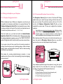
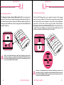
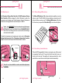
www.accutone.com
Amplifier
A20 OMEGA telephone & multimedia amplifier
user manual & installation guide
Printed in Hong Kong
AASA20 OmegaR2007JUN
Accutone and the logo device are registered trademarks of Accutone Technologies Limited.
© Copyright 2007 Accutone Technologies Limited, All rights reserved, Do not copy or re-distribute any contents.
Introduction.
table of content.
This installation guide and user manual contains the following contents:
PART A
telephone & multimedia amplifier for headset.
Thank you for purchasing the Accutone A20 Omega Telephone
Amplifier. This unit is designed to be paired with an Accutone telephone
headset, which you can find more information from your distribution
agent, or from our website. The A20 Omega telephone amplifier is an
entirely new design from our existing models, and is tailor-made for
intensive usage in call centers or large corporations. With enhanced
compatibility to fit with almost all telephones in the market, and top-end
acoustics for noisy environments, the A20 Omega is the ultimate tool for
professional contact agents.
A.2.1 connect to telephone
A.2.2 connect to computer
A.2.3 connect to telephone headset
A.2.4 inserting batteries
A.2.5 external DC supply
A.2.6 headset hanger components
A.2.7 hanger installation part 1
A.2.8 hanger installation part 2
A.2.9 hanger installation part 3
PART B
Begin to Operate.
B.1 Operating the Unit.
B.1.1 switch on the power
B.1.2 headset/handset application
B.1.3 telephone/PC mode selection
B.1.4 mute function
B.1.5 pairing the amplifier to your telephone
B.1.5.1 telephone configuration switch
B.1.5.2 transmission/microphone connection paring
B.1.6 reception volume
B.1.7 transmission volume
B.1.8 gain control
B.1.9 online/muting LED indication
B.1.10 low battery sound indication
Other highlight features of the A20 Omega include: low-power
consumption for longer battery lifetime, LED indication for online and
muting status, headset hanger and handset selection switch...etc.
Now please spend a few moments to read through this user manual
before connecting the A20 Omega unit to your telephone. After
familiarizing with the features and functions, you will surely enjoy the
freedom and convenience this unique device has to offer you.
B.2 Troubleshooting
Connect to fixed
line telephone
Connect to PC or
other devices
Getting Comfortable.
A.1 Understanding the Controls.
A.2 Connection and Preparations.
PART C
Accessories & Specifications.
C.1 Accessories
C.2 Specifications
A20 Omega
1
understanding the controls.
getting comfortable.
A.1
Learning about the interface & controls.
7
8
Part A. Getting Comfortable
9
1
2
3
4
5
6
10
11
12
13
14
15
16
17
18
A.1 Understanding the Controls.
A.2 Connection and Preparations.
MAIN SWITCHES AND INTERFACE
1.
2.
3.
4.
5.
6.
7.
8.
9.
10.
11.
12.
13.
14.
15.
16.
17.
18.
2
External DC Supply Jack (9V DC)
Modular Jack for Telephone Handset
Modular Jack for Input from Telephone Unit
Battery Compartment Door
PC/Recording Machine Jack
Microphone Selector
Telephone Configuration Switch
Mute Switch
Power On/Off Switch
Microphone Volume Control Slide Switch
Muting LED Indicator
Reception Volume Control Slide Switch
Telephone/PC Selection Switch
Online LED Indicator
Reception Volume Gain Controller
Modular Jack for Telephone Headset
Headset/Handset Application Switch
Microphone Volume Gain Controller
part a. getting comfortable.
3
connection & preparations.
Hooking all the parts together!
connection & preparations.
A.2
A.2
Hooking all the parts together!
A.2.1 Connect to Telephone
A.2.3 Connect to Telephone Headset
Unplug the handset cord from your telephone base unit and insert it to the
Modular Jack for Telephone Handset (2). Use the phone cord provided
with RJ-11 modular plug on both ends to connect the control unit to your
telephone. Plug one end of the cord to your base unit (A) and the other end
to the Modular Jack for Input from Telephone Unit (3) on the back of the
unit.
The A20 Omega Telephone Amplifier provides the choice of using any
Accutone Telephone Headsets equipped with a RJ-11 Modular Plug (except
TM1200) according to your preference.
A
2
On all Accutone Telephone Headsets pairable to an amplifier, they should be
equipped with a Quick Disconnecting Cable (QD). This special feature is
designed for users who are always on the move. Simply unplug the cable as
shown below when you need to leave your desk, and plug it together again
to continue using the unit.
3
Plug in the telephone headset to the RJ-11 Modular Jack for Telephone
Headset (16) on the front panel of the A20 Omega amplifier.
A.2.2 Connect to Computer
The A20 Omega supports
connection to both PC soundcard as
well as most recording devices in the
market. Comes together with the
amplifier is a Soundcard/Recording
-Jack cable (J) which connects to
the PC/Recording Machine Jack
(5). Connect the cable, and plug the
plugs as illustrated to the respective
jack in your soundcard or use the
recording jack for plugging your
recording machine.
4
to soundcard
to recording machine
J
QD
5
16
part a. getting comfortable.
part a. getting comfortable.
5
connection & preparations.
connection & preparations.
A.2
A.2
Hooking all the parts together!
Hooking all the parts together!
A.2.4 Inserting Batteries
A.2.6 Headset Hanger Components
Slightly depress the Battery Compartment Door (4) and slide it
outwards. Install batteries with polarities according to the battery diagram
inside the compartment. Two UM-3 (AA) batteries are required. Alkaline
batteries are recommended.
Along with your A20 Omega amplifier, you should be able to find the
following 3 pieces of components for the headset hanger. There are one
plastic and two metal components.
I
II
III
4
AA Alkaline
AA Alkaline
2 x AA Batteries
A.2.7 Hanger Installation Part 1
A.2.5 External DC Supply
The unit provides the choice of using an external DC supply instead of
batteries. You can connect an AC Adaptor to the External DC Supply Jack (I).
When purchasing an AC adaptor, make sure the output voltage is 9V DC,
and current is 500mA, but we recommend you contact your local dealer for
information.
Insert the metal piece (I) first into the bottom of the A20 Omega amplifier as
illustrated, make sure that it fits perfectly into the track, you should be able
to feel a click, which means the metal is fastened to the plastic bottom. Then,
gently turn the metal piece inwards towards the amplifier so that the entire
piece is fastened to the bottom, as shown below.
*AC Adaptor not included!
1
I
6
part a. getting comfortable.
part a. getting comfortable.
7
begin to operate.
connection & preparations.
A.2
Hooking all the parts together!
A.2.8 Hanger Installation Part 2
II
Upon completion of the above, attach the
remaining metal piece (II) to the plastic
piece (III) as shown on the right. Make sure
that the hanging curves (A) and the cord
winders (B) are facing opposite directions.
A
B
The hanging curves (A) will be where you
hang your headset, and the cord winders
(B) are designed for tangling your long
headset cords around it, for tidiness and
space-saving.
III
B.1 Operating the Unit.
A.2.9 Hanger Installation Part 3
II
III
I
Feature Highlight!
8
Part B. Begin to Operate
B.2 Troubleshooting.
The final step is to place the assembled
pieces (II) & (III) on top of the metal
piece (I), which should already be
fastened to the bottom of the amplifier
box. Gently insert the metal rods (I)
into the holes at the bottom of the
plastic piece (III) until resistance.
This will complete the simple
installation of the hanger, from now on,
you can enjoy the convenience of
hanging your headset neatly with this
new feature of the A20 Omega.
part a. getting comfortable.
9
operating the unit.
operating the unit.
How do I use this device? What can I do with it?
B.1
B.1
How do I use this device? What can I do with it?
B.1.1 Switch on the Power
B.I.3 Telephone/PC Mode Selection
Now you can turn on the Series A20 Omega by switching on the Power
ON/OFF Switch (9). Although the Series A20 Omega will return to
standby mode automatically after each extended inactivity, you still want to
turn it off when decided not to use for a prolonged period of time to cut off
the least consumption of power.
The Telephone/PC Selection Switch (13) provides the option to switch
from fixed-line telephone mode to PC VoIP mode. Of course, your A20
Omega must be plugged into your PC’s soundcard for this to function.
13
123456
9
Feature Highlight!
B.I.4 Mute Function
B.1.2 Headset/Handset Application
The Headset/Handset Application Switch (17) is for you to choose
between using the handset of your telephone base unit or the telephone
headset provided.
The Mute Switch (8) enables you to place a caller on hold by pressing it
down. When the button is pressed down, the caller cannot hear from you,
but you can still hear from them and the Muting LED Indicator (11) will
turn on.
17
8
10
part b. begin to operate.
part b. begin to operate.
11
operating the unit.
operating the unit.
How do I use this device? What can I do with it?
B.1
B.1
How do I use this device? What can I do with it?
B.1.5 Pairing the Amplifier to your Telephone
B.1.5.2 Transmission/Microphone Connection Pairing
B.1.5.1 Telephone Configuration Switch
The Microphone Selector (6) at the back of the Series A20 Omega
amplifier allows you to select the proper setting so that the other end can
hear your voice clearly. The switch has 4 positions, which are (1-2-3-4). Do
not alter the Telephone Configuration Switch (7) after you have
completed the previous step. This step only configures the microphone
connection.
Different telephones have a different pin configuration, users have to pair
the amplifier to the telephone model before it can operate effectively. The
Telephone Configuration Switch (7) at the side panel allows you to select
the proper setting so that the unit will work with your telephone base unit.
The switch has 6 positions, which are (1 - 2 - 3 - 4 - 5 - 6).
Wear the headset over your head and switch the Headset/Handset
Application Switch (17) to the Headset position. Make sure to turn down
the volume adjustment to protect your ear. Now select in turn the 6position Configuration switch one by one until you can hear a clear dial tone.
!
Caution: Make sure you turn down the microphone volume (10) before each trial,
because different microphone settings varies greatly in sensitivity, if the
microphone volume is set too high when switched to a sensitive setting, the
speaker may SQUEAL, which can cause damage to the user's ear and the unit.
Dial a telephone number. If the person on the other side cannot hear your
voice, then select the Microphone Selector (6) one by one until the
person can hear your voice clearly. Repeat this step if necessary.
If you receive a clear dial tone sound, then the receiving connection is
working. Note that there may be 2 matching settings, choose the clearer
setting or either one if both perform the same. There is at least one setting
which matches your telephone.
6
After pairing the receiving (speaker/incoming) connection, in some
telephones you will have to select the transmitting (microphone/outgoing)
connection as well.
If your telephone specifies the type of microphone it is using, then you can
simply choose from the chart below the correct type of microphone
according to the positions of the Microphone Selector (6):
123456
1 = Ceramic Microphone
2 = Electret Condenser Microphone (the most frequently used)
3 = Dynamic Microphone (low sensitivity level)
4 = Carbon Microphone (high sensitivity level)
7
12
1 2 3 4
part b. begin to operate.
part b. begin to operate.
13
operating the unit.
operating the unit.
How do I use this device? What can I do with it?
B.1
B.1
How do I use this device? What can I do with it?
B.1.6 Reception Volume
B.1.7 Transmission Volume
The Reception Volume Control Slide Switch (12) is for adjusting the
volume of the sound to the headset. By sliding the button left and right, you
can obtain a desired volume. Varying from different telephone systems, the
volume gain may be different, however, setting the level to the middle should
be safe for initial use.
The Series A20 Omega allows you to adjust the volume of the outgoing
sound on the main interface. To fine tune this transmission volume, make
sure that the slide control is adjusted to the middle on initial adjustment,
then place a call and talk as usual using the headset. Slowly slide the
Microphone Volume Control Slide Switch (10) until the desired level is
reached. The person talking to you at the other end should be able to tell
you when the optimum sound and tone level is reached.
10
12
Caution: It is recommended that user should avoid switching the volume to the
maximum at all times, as over-adjustment of the Reception Volume Control, may
cause headset to SQUEAL (feedback sound), which can cause damage to the user's
ear as well as the headset and the amplifier.
!
!
14
part b. begin to operate.
Caution: It is recommended that user should avoid switching the volume to the
maximum at all times, as over-adjustment of the Microphone Volume Control, may
cause headset to SQUEAL (feedback sound), which can cause damage to the user's
ear as well as the headset and the amplifier.
part b. begin to operate.
15
operating the unit.
operating the unit.
B.1
How do I use this device? What can I do with it?
B.1
How do I use this device? What can I do with it?
B.1.8 Gain Control
B.1.9 Online Muting LED Indication
Both Reception Volume Gain Controller (15) & Microphone Volume
Gain Controller (18) are designed for Setup Technicians to adjust the
transmission and reception level if both Reception Volume & Transmission
Volume are not enough after fine tuned in the step B.1.6 & B.1.7.
The Online LED Indicator (14) indicates whether the amplifier is currently
online or muted. The LED will be lit during a telephone conversation, and it
will shut off after you end your call. The Muting LED Indicator (11) will be
lit in blue when you pressed the Mute Switch (8) to mute the microphone.
Caution: Users SHOULD NOT alter these settings unless specified, improper
setting to these gain controllers may cause unit to cease functioning properly.
Over-adjustments to any of the controllers may cause SQUEALING (feedback),
which can cause severe damage to the user's ear, and can also result with damage
to the headset and the amplifier.
!
11 Muting Indicator
To adjust the transmission and reception gain, slowly rotate the Reception
Volume Gain Controller (15) or Microphone Volume Gain Controller
(18) with a small screwdriver pin until the desired level is reached.
14 Online Indicator
Feature Highlight!
Screwdriver
15
B1.10 Low Battery Sound Indication
18
Gain Controller
When the A20 Omega amplifier’s battery is running low, users will be warned
by a repeating “beep” sound. The sound will only be heard by the user, not
the call on the other end. The amplifier will remain operational for a short
period of time, meanwhile users should replace batteries immediately.
LOW BATTERY
Once this is set, there should be no need to make further adjustments
in the future.
i
Beep Beep Beep
Feature Highlight!
16
part b. begin to operate.
part b. begin to operate.
17
troubleshooting.
troubleshooting.
I can't seem to make it work, what should I do?
I hooked everything
up exactly as
suggested, but there
is still no response
from my A20 Omega
unit.
items to check
Lift the handset or press the Line button on the phone, is
#
the Online LED Indicator on?
If not, check to make sure (A) the power switch is on, (B)
#
batteries are installed properly, (C) the handset/headset
switch is at headset position.
Select through the 6-position configuration switch until the
#
Online LED turns on.
Select through the microphone selector switch to see if
#
there is a position that turns on the LED.
If the Online LED lights up, then your A20 Omega is
#
functioning.
The Online LED is
on, but I cannot
hear anything from
the other side.
Is the Reception Volume Control set too low?
#
Make sure the headset is properly plugged into the front
#
Headset Jack on the amplifier.
Try switching to use the handset to see if there is dial tone
#
coming from the telephone.
Make sure the Quick Disconnector of your headset is
#
connected.
My Caller cannot
hear me at all or
cannot hear me very
well.
Make sure the Mute button is not pressed down.
#
Check to see if the Microphone Volume is set too low.
#
Is the Low-battery beeper sound on, if so, replace new
#
batteries.
Select through the microphone selector to find a better
#
setting.
I hear my voice too
loud and there is a
squealing sound.
If the Microphone Volume Control is set too high or the
#
Reception Volume Control is set too high, reduce either
one or both to find the perfect settings.
The other end
cannot hear me well
no matter which mic
setting I chose.
It is possible that some telephones have unusual
#
microphone input requirements, A20 Omega is capable of
expanding the compatibility by adjusting the Microphone
Volume Gain Control, but you should contact your
technical support for the adjustments.
18
I can't seem to make it work, what should I do?
B.2. Troubleshooting - Subsequent Problems
B.2. Troubleshooting - First Time Installation
problem
B.2
B.2
part b. troubleshooting.
items to check
problem
The device was
working fine, but
after a prolonged
period of inactivity,
it has no response
when I turn it on.
(Online LED doesn't
come on when I pick
up the phone.)
Make sure all the cables are properly hooked up, especially
#
the patch cable connecting the amplifier with the
telephone terminal.
Then, check to make sure the Handset/headset Switch is
#
set at HEADSET.
Has the Low-battery sound indication been heard recently,
#
if so, you should replace new batteries. If you are not sure,
try to replace new batteries for now.
Now make sure there is signal coming from the telephone,
#
you can test this by selecting Handset/headset Switch to
HANDSET and pick up the handset to check if there is a
dial-tone. If no, then the problem is with the telephone or
the network; if yes, then switch the Handset/headset
Switch to HEADSET and the Online LED should light up.
During a telephone
conversation, the
voice transmission
or reception
suddenly ceased.
Make sure you change your batteries whenever you heard
#
a repeating “beep” sound, as mic-transmission may be
affected if the power voltage is dropped to a certain level.
The amplifier will not drop any reception signal (speaker
#
side), so if you hear interruptions to the speaker side,
make sure the headset plug is fastened, and then the Quick
Disconnector is firmly connected.
The caller on the
other side can hear
my breathing sound,
and the noise is too
loud.
Telephone calls made to different systems and locations
#
may vary in their reception level. To reduce breathing
sound noises, you should keep the foam windscreen
attached to the microphone on your Accutone headset, or
adjust the Microphone Volume according to different calls.
The voice reception
and transmission are
fine, but I cannot see
any LED indication,
online or mute.
When muted, the Online LED Indicator should lit up.
#
*For problems not listed in the above section, try refer back to FAQ:troubleshooting section in
our website - http://www.accutone.com
part b. troubleshooting.
19
accessories & specifications.
accessories & specifications.
C.1
Any additional information I should know?
C.1 Accessories
The A20 Omega kit should include:
1. One set of the A20 Omega Amplifier Unit.
2. Telephone Patch Cable with RJ-11 Modular Plugs.
3. Headset Hanger Components (3 pieces).
4. Soundcard/Recording Jack Cable.
5.Screwdriver Pin
Part C. Accessories & Specifications
C.1 Accessories.
C.2 Specifications.
C.2 Specifications
Standard Operating Voltage
Operating Current (Max)
Standby Current
Standby Mode Activation
Amplifier Gain
- Receive
- Transmit
Battery
Adapter DC Input
(Adapter not included)
3V DC
9 mA (Max)
0.01 mA
immediately if no signal
10~12 dBmV (Max)
20 dBmV Typical (Max)
UM-3 x 2 (size "AA")
9V DC 500 mA
FCC Registration Information to the end user
Modifications not authorized by the manufacturer may void users authority to operate this device.
NOTE: This equipment has been tested and found to comply with the limits for a Class B digital device,
pursuant to Part 15 of the FCC Rules. These limits are designed to provide reasonable protection
against harmful interference in a residential installation. This equipment generates, uses and can radiate
radio frequency energy and, if not installed and used in accordance with the instructions, may cause
harmful interference to radio communications. However, there is no guarantee that interference will
not occur in a particular installation. If this equipment does cause harmful interference to radio or
television reception, which can be determined by one or more of the following measures:
- Reorient or relocate between the equipment and receiver
- Increase the separation between the equipment and receiver
- Connect the equipment into an outlet on a circuit different from that to which the receiver is
connected
- Consult the dealer or an experienced radio/TV technician for help.
Trademark and Ownership
Accutone and the logo design combined are trademarks or registered trademarks of Accutone
Technologies Limited.
20
part c. accessories & specifications.
21