1
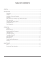
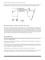
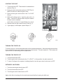
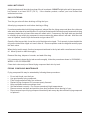
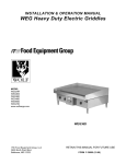
INSTALLATION &
OPERATION MANUAL
GHF SERIES HEAVY DUTY
RANGE MATCHING GAS FRYERS
MODELS
GHF91
GHF90
ML-135503
ML-135504
GHF91
For additional information on Vulcan-Hart Company or to locate an authorized
parts and service provider in your area, visit our Web site at www.vulcanhart.com
VULCAN-HART
COMPANY,
P.O.
BOX
696,
LOUISVILLE,
KY
40201-0696,
TEL.
(502)
778-2791
FORM 35609 (09-03)
IMPORTANT FOR YOUR SAFETY
THIS MANUAL HAS BEEN PREPARED FOR PERSONNEL QUALIFIED TO INSTALL GAS
EQUIPMENT, WHO SHOULD PERFORM THE INITIAL FIELD START-UP AND
ADJUSTMENTS OF THE EQUIPMENT COVERED BY THIS MANUAL.
POST IN A PROMINENT LOCATION THE INSTRUCTIONS TO BE FOLLOWED IN THE
EVENT THE SMELL OF GAS IS DETECTED. THIS INFORMATION CAN BE OBTAINED
FROM THE LOCAL GAS SUPPLIER.
IMPORTANT
IN THE EVENT A GAS ODOR IS DETECTED, SHUT
DOWN UNITS AT MAIN SHUTOFF VALVE AND
CONTACT THE LOCAL GAS COMPANY OR GAS
SUPPLIER FOR SERVICE.
FOR YOUR SAFETY
DO NOT STORE OR USE GASOLINE OR OTHER
FLAMMABLE VAPORS OR LIQUIDS IN THE
VICINITY OF THIS OR ANY OTHER APPLIANCE.
WARNING
IMPROPER INSTALLATION, ADJUSTMENT,
ALTERATION, SERVICE OR MAINTENANCE CAN
CAUSE PROPERTY DAMAGE, INJURY OR
DEATH. READ THE INSTALLATION, OPERATING
AND
MAINTENANCE
INSTRUCTIONS
THOROUGHLY BEFORE INSTALLING OR
SERVICING THIS EQUIPMENT.
IN THE EVENT OF A POWER FAILURE, DO NOT
ATTEMPT TO OPERATE THIS DEVICE.
© VULCAN-HART COMPANY, 2003
–2–
TABLE OF CONTENTS
GENERAL .............................................................................................................................................4
INSTALLATION ....................................................................................................................................4
Unpacking .................................................................................................................................4
Location .....................................................................................................................................4
Installation Codes and Standards ............................................................................................5
Assembly ...................................................................................................................................5
GHF Series Fryers - Battery Type (Heavy Duty Style) .........................................................6
Gas Connections ......................................................................................................................6
Testing the Gas Supply System ..............................................................................................7
Leveling the Fryer .....................................................................................................................7
Flue Connections ......................................................................................................................7
OPERATION .........................................................................................................................................8
Controls .....................................................................................................................................8
Before First Use ........................................................................................................................8
Adding Liquid Frying Compound ..............................................................................................8
Lighting the Pilot ........................................................................................................................9
Turning the Fryer On ................................................................................................................9
Turning the Fryer OFF ..............................................................................................................9
High Limit Device .................................................................................................................... 10
Daily Filtering ...........................................................................................................................10
Frying Compound Maintenance .............................................................................................10
Cleaning ...................................................................................................................................11
MAINTENANCE ..................................................................................................................................12
Vent .......................................................................................................................................... 12
Service and Parts Information ................................................................................................12
–3–
Installation, Operation and Care of
MODEL GHF91 GAS FRYERS
PLEASE KEEP THIS MANUAL FOR FUTURE REFERENCE
GENERAL
Vulcan fryers are produced with quality workmanship and material. Proper installation, usage and
maintenance of your fryer will result in many years of satisfactory performance.
Standard equipment on the fryer includes 6" (15 cm) adjustable legs, a lift-off backsplash, twin baskets
and a stainless steel fry tank. Optional accessories available include extra twin baskets, a stainless
steel tank cover, a large single basket, timer, less-legs base, and a quick-disconnect gas hose.
Thoroughly read this entire manual and carefully follow all of the instructions provided.
INSTALLATION
Before installing, verify that the type of gas supply (natural or propane) agree with the specifications
on the rating plate located on the inside of the fryer door panel. If the supply and equipment
requirements do not agree, do not proceed with the installation. Contact your dealer or Vulcan-Hart
Company immediately.
The fryer must be restrained with adequate ties to prevent tipping when installed in order to avoid the
splashing of hot liquid.
UNPACKING
This fryer was inspected before leaving the factory. The transportation company assumes full
responsibility for safe delivery upon acceptance of the shipment. Immediately after unpacking, check
for possible shipping damage. If the fryer is found to be damaged, save the packaging material and
contact the carrier within 15 days of delivery.
Carefully unpack fryer and place in a work-accessible area as near to its final installed position as
possible. Do not use the fryer door or its handle to lift or move the fryer. The crumb tray, backsplash
and two fryer baskets are packed in the fryer.
LOCATION
The equipment area must be kept free and clear of combustible substances.
When installed, minimum clearance from combustible construction must be 6" (15 cm) at the
sides and 6" (15 cm) at the rear. The minimum clearance from non-combustible construction is
0" at the sides and rear. There must be at least 16" (40 cm) clearance between the fryer and any
open top flame units. The fryer may be installed on combustible floors.
–4–
The installation location must allow adequate clearances for servicing and proper operation.
A minimum front clearance of 36" (91 cm) is required.
Do not obstruct the flow of combustion and ventilation air. Adequate clearance for air openings into the
combustion chamber must be provided. Make sure there is an adequate supply of air in the room to
replace air taken out by the ventilating system. This will prevent fryer function from being affected by
a reduced atmospheric pressure.
Do not permit fans to blow directly at the fryer. Wherever possible, avoid open windows next to the
sides or back of the fryer. Avoid wall-type fans which create air cross currents within the room.
INSTALLATION CODES AND STANDARDS
Your Vulcan fryer must be installed in accordance with:
In the United States of America:
1. State and local codes.
2. National Fuel Gas Code, ANSI-Z223.1 (latest edition). Copies may be obtained from The American
Gas Association, Inc., 1515 Wilson Blvd., Arlington, VA 22209.
3. National Electrical Code, ANSI/NFPA-70 (latest edition). Copies may be obtained from The
National Fire Protection Association, Batterymarch Park, Quincy, MA 02269.
In Canada:
1. Local codes.
2. CAN/CGA-B149.1 Natural Gas Installation Code (latest edition). (Copies may be obtained from The
Canadian Standard Association, 178 Rexdale Blvd., Etobicoke, Ontario, Canada M9W 1R3.)
3. Canadian Electrical Code, CSA C22.2 No. 3 (latest edition). Copies may be obtained from The
Canadian Standard Association, 178 Rexdale Blvd., Etobicoke, Ontario, Canada M9W 1R3.
ASSEMBLY
Fasten backsplash at rear of fryer. Place crumb tray in the fry tank. Hook fry baskets onto the
backsplash.
Legs/Casters
Toe bases or legs ordered with GHF Series Fryers will be attached to the fryer.
NOTICE: When the fryer is mounted on casters, it must be installed with the casters supplied, a
connector (not supplied by Vulcan) complying with either ANSI Z21.69 (latest edition) or CAN/CGA6.16 (latest edition), and a quick-disconnect device complying with either ANSI Z21.41 (latest edition)
or CAN1-6.9 (latest edition). It must also be installed with restraining means to guard against
transmission of strain to the connector, as specified in the appliance manufacturer's instructions.
–5–
Attach the restraining device at the rear of the fryer (Fig.1).
If disconnection of the restraint is necessary, turn off the gas supply before disconnection. Reconnect
this restraint prior to turning the gas supply on and returning the fryer to its installation position.
Fig. 1
GHF SERIES FRYERS - BATTERY TYPE (HEAVY DUTY STYLE)
Set all fryers in line with each other and adjacent ranges (16" [40 cm] clearance required between fryer
and open top flame units). Remove control panels for access to union connections or manifold pipes.
Screw each union finger-tight to adjoining connection. Do not overtighten. Tighten each union in turn,
ensuring that the gas manifold is not pulled to the left or right by overtightening the unions. When all
fryers in the battery are connected finger-tight, then tighten with a pipe wrench. Always use pipe joint
compound that is resistant to the action of liquid petroleum gases on unions.
GAS CONNECTIONS
CAUTION: All gas supply connections and any pipe joint compound used must be resistant to
the action of propane gases.
All fryers are equipped with fixed orifices for use with either natural or propane gas, as ordered, and
no adjustment is necessary.
Fryers for operation on natural or propane gas must have a pressure regulator with an outlet pressure
of 4.0" Water Column for natural gas supply, and 10.0" Water Column for propane gas supply. These
pressure regulators are available from Vulcan-Hart.
Codes require that a gas shutoff valve be installed in the gas line ahead of the fryer.
Connect gas supply to the fryer. The gas supply line must be at least the equivalent of 3/4" (19 mm) iron
pipe. Make sure the pipes are clean and free of obstructions, dirt, and piping compound.
–6–
WARNING: PRIOR TO LIGHTING, CHECK ALL JOINTS IN THE GAS SUPPLY LINE FOR LEAKS.
USE SOAP AND WATER SOLUTION. DO NOT USE AN OPEN FLAME.
After piping has been checked for leaks, fully purge all piping receiving gas to remove air.
TESTING THE GAS SUPPLY SYSTEM
When test pressures exceed 1/2 psig (3.45 kPa), the fryer and its individual shutoff valve must be
disconnected from the gas supply piping system.
When test pressures are 1/2 psig (3.45 kPa) or less, the fryer must be isolated from the gas supply
system by closing its individual manual shutoff valve.
LEVELING THE FRYER
Once gas connections have been made, place a spirit level on top of the fryer. Adjust the legs or leveling
screws to ensure that the fryer is level front-to-back and side-to-side.
FLUE CONNECTIONS
Adequate ventilation should be provided by a hood with vent and exhaust fan. Never make flue
connections directly to the fryer. A minimum clearance of 18" (45 cm) must be maintained from the
termination of the flue vent to the filters of the hood venting system.
Do not obstruct the flow of flue gases from the flue duct located on the rear of the fryer. It is
recommended that the flue gases be ventilated to the outside of the building through a ventilation
system installed by qualified personnel.
Information on the construction and installation of ventilating hoods may be obtained from the "Standard
for Removal of Vapors from Commercial Cooking Equipment," NFPA #96 (latest edition), available from
the National Fire Protection Association, Batterymarch Park, Quincy, MA 02269.
–7–
OPERATION
WARNING: HOT OIL AND PARTS CAN CAUSE BURNS.
CLEANING AND SERVICING THE FRYER.
USE CARE WHEN OPERATING,
WARNING: SPILLING HOT OIL CAN CAUSE SEVERE BURNS.
WITHOUT DRAINING ALL OIL FROM THE TANK.
DO NOT MOVE FRYER
CONTROLS - "G" MODELS
Thermostat
—
Turns fryer on or off, and maintains temperature of oil in tank.
BEFORE FIRST USE
Cleaning
Using a non-corrosive, grease-dissolving commercial cleaner, clean the protective metal oils from all
surface parts and the fry tank interior. Follow the cleaner manufacturer's directions. Drain through the
valve in the bottom. Rinse thoroughly and drain. Be sure to remove all traces of cleaner; it can affect
the food taste. Wipe fry tank completely dry with a soft clean cloth.
Clean all fryer accessories. Rinse all parts thoroughly and wipe dry.
Seasoning
Light seasoning of the backsplash area is required to avoid possible surface corrosion. With a soft,
lint-free cloth, apply a thin layer of cooking oil over entire backsplash area. This should also be done
after every cleaning.
ADDING LIQUID FRYING COMPOUND
Melting solid frying compound in the fry tank is not recommended. The fry tank will be damaged
and the frying compound will be scorched. Melt solid frying compound in a separate container, being
careful to just melt and not overheat it; then carefully pour into fry tank.
Fill the fry tank to a depth of 2" (5 cm) above the tubes. Approximate frying compound quantities are:
Model GHF91 - 35 lb. (15 kg).
Do not overfill fry tank.
Add fresh liquid frying compound as needed.
–8–
LIGHTING THE PILOT
1. Turn thermostat OFF. Thermostat is located behind
the door (Fig. 4).
2. Push gas control valve knob and turn to OFF (Fig. 5).
Wait 5 minutes for unburned gas to vent.
3. Push and turn gas control valve to the "I" in PILOT
(Fig. 6).
4. While still holding knob in, light the pilot with a lit
taper. Continue to depress knob until pilot remains
lit when knob is released.
If pilot does not remain lit, repeat Steps 2, 3, and 4.
5. Depress and turn gas control knob to ON (Fig. 7).
6. If gas supply is interrupted, repeat Steps 1-5.
Fig. 4
Fig. 5
Fig. 6
Fig. 7
TURNING THE FRYER ON
To turn the fryer on, set the thermostat knob to the desired temperature. After the set temperature has
been reached, the gas control shuts off gas flow to the burners. The pilot remains lit. The burners will
cycle on and off, maintaining the set temperature.
TURNING THE FRYER OFF
1. Turn the thermostat OFF.
2. Turn the gas control valve knob to the "I" in PILOT. In this position, the pilot remains lit.
3. To shut off all gas to the system, including the pilot, turn the gas control valve knob to OFF.
EXTENDED SHUTDOWN
1. Turn the manual gas shutoff valve OFF.
2. Turn the thermostat knob OFF.
3. Turn the gas control valve knob to OFF.
Apply a thin film of cooking oil to the tank interior and the flue housing to inhibit rust.
–9–
HIGH LIMIT DEVICE
A high limit device will shut the fryer down if the oil overheats. DO NOT relight pilot until oil temperature
has lowered to at least 350°F (176°C). If the situation persists, contact your local Vulcan-Hart
authorized servicer.
DAILY FILTERING
Turn the gas valve off when draining or filling the fryer.
Allow frying compound to cool before draining or filling.
If you have used melted solid frying compound, always filter the frying compound when the cold zone
area under the tubes is hot and liquefied. A cold fryer heated up will not drain properly because the frying
compound under the cold zone tube area will remain solid. If necessary, the drain stick may be used
to carefully stir up solid frying compound to an area above the tubes where it will melt. After the cold
zone is liquefied, turn the fryer thermostat and gas valve OFF.
Open the filter bag and slip it over the end of the drain valve nipple. Tie it securely in place behind the
ring on the drain valve nipple so it won't slide off. Place receptacle under the bag and carefully open
the drain valve.
When the fry tank is empty, flush out scraps and sediment in the fry tank with a small amount of warm
oil. Allow fry tank to drain thoroughly.
Remove filter bag, dispose of crumbs, and wash filter bag.
If it is necessary to clean the fry tank more thoroughly, follow the procedures shown in CLEANING —
WEEKLY OR AS REQUIRED.
Close drain valve and pour filtered frying compound back into fry tank.
FRYING COMPOUND MAINTENANCE
Frying compound life may be extended by following these procedures:
•
•
•
•
•
•
•
•
Do not salt foods over the fryer.
Use good quality frying compound.
Filter frying compound daily at a minimum.
Replace frying compound if it becomes poorly flavored.
Keep equipment and surroundings clean.
Set thermostats correctly. Do not use excessively high temperatures.
Remove excess moisture and particles from food products before placing in fryer.
Dip out several cups of frying compound from the fry tank every day and add fresh frying compound
to replace it.
– 10 –
CLEANING
CAUTION: Do not spray with hose or steam cleaner. Doing so will cause extensive damage (not
covered under warranty).
Daily
Clean your fryer regularly. If regular cleaning is neglected, grease will be burned on and discolorations
may form. These may be removed by washing with detergent or soap and water. Particularly stubborn
discolorations may be removed with a self-soaping scouring pad or a paste made of water and a mild
scouring powder applied with a plastic open pad or sponge. Do not use standard steel wool on stainless
steel finishes. Pieces of the steel wool will adhere to the stainless steel and cause rusting.
Always rub in the direction of the polish lines on the stainless steel front to preserve the original finish.
Keeping the fryer exterior clean and free of accumulated grease will prevent stubborn stains from
forming. Wash all exterior surfaces at least once daily. Use a cloth with warm water and a mild soap
or detergent. Follow with a clear rinse, then dry.
Weekly or as Required
1.
Drain and strain frying compound into a clean container and refrigerate if necessary.
2.
Close drain valve and fill tank with hot water. Add a good grade of non-corrosive, greasedissolving commercial cleaner.
3.
Set thermostat to 300°F (148°C) and bring to a boil. Boil long enough to loosen all "varnish" and
"carbon" (15-20 minutes). If necessary, scrub inside of the tank with a long-handled pot brush. Do
not leave fryer unattended.
4.
Drain cleaning solution from the fry tank slowly so you can clean side walls as exposed.
5.
Open the drain valve completely and thoroughly rinse tank with clean water. Be sure to remove
all traces of cleaner.
6.
Close drain valve and refill tank with clean hot (minimum 140°F [60°C]) water. Add 1 cup
(226.8 g) of vinegar to neutralize alkaline left by the cleaner. Bring solution to a boil and allow it
to stand for a few minutes.
7.
Drain tank and rinse thoroughly with clear hot water. All traces of cleaner must be removed; it can
affect the food taste. Thoroughly dry fry tank.
8.
Close the drain valve.
9.
Add liquid frying compound to the proper level.
Cleaning Stainless Steel
Stainless steel may be cleaned with ordinary soap or detergent and water. To prevent water spots and
streaks, rinse equipment thoroughly with warm water and wipe dry with a soft clean cloth. The addition
of a rinsing agent will also help prevent spotting.
– 11 –
Fingerprints
Fingerprints are sometimes a problem on highly polished surfaces of stainless steel. They can be
minimized by applying a cleaner that will leave a thin, oily or waxy film. Wipe cleaner on and remove
excess with a soft dry cloth. After using, subsequent fingerprints will usually disappear when wiped
lightly with a soft cloth containing a little of the cleaner. If the surface is especially dirty to start with,
wash first with soap or detergent and water.
Burned On Foods and Grease
Soaking with hot soapy water will help greatly to remove burned on foods and grease. Stubborn
deposits can be removed with scouring powder mixed into a paste and applied with stainless steel wool
or sponges.
Precautions
When scraping off heavy deposits of grease or oil from stainless steel equipment, never use ordinary
steel scrapers or knives. Particles of ordinary steel may become embedded in, or lodge on, the surface
of the stainless steel. These will rust, causing unsightly stains. Where it is necessary to scrape, use
stainless steel, wood, plastic, or rubber tools, or stainless steel wool.
MAINTENANCE
WARNING: HOT OIL AND PARTS CAN CAUSE BURNS.
CLEANING AND SERVICING THE FRYER.
USE CARE WHEN OPERATING,
WARNING: SPILLING HOT OIL CAN CAUSE SEVERE BURNS.
WITHOUT DRAINING ALL OIL FROM THE TANK.
DO NOT MOVE FRYER
VENT
Annually, when the fryer is cool, check the flue and clear any obstructions.
SERVICE AND PARTS INFORMATION
To obtain service and parts information concerning this fryer, contact the Vulcan-Hart Service Depot
in your area (refer to listing supplied with the fryer), or Vulcan-Hart Company Service Department at
the address or phone number shown on the front cover of this manual.
FORM 35609 (09-03)
– 12 –
PRINTED IN U.S.A.