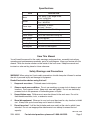
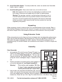
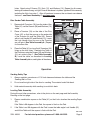
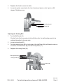
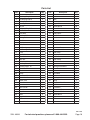
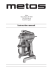
1
WOOD BELT SANDER
6 X 48 INCHES
40643
ASSEMBLY AND OPERATING
INSTRUCTIONS
®
3491 Mission Oaks Blvd., Camarillo, CA 93011
Visit our Web site at http://www.harborfreight.com
Copyright© 1999 by Harbor Freight Tools®. All rights reserved. No portion of this
manual or any artwork contained herein may be reproduced in any shape or
form without the express written consent of Harbor Freight Tools.
For technical questions and replacement parts, please call 1-800-444-3353
Specifications
ITEM
Motor
Speed
Power Input
DESCRIPTION
1 HP (peak), 110V, Single Phase,
60 Hz, 3,450 RPM
Belt: 1,440 FPM
Disc: 1,850 RPM
Continuous: 12 amps;
No Load: 7.8 amps
Table
6 x 10⁻³/16 inches; Tilt: 45 degrees
Net Weight
139 lbs.
Power Switch
On/Off with removable locking key
Miter Gauge
0 to 60 Degrees
Miter Slots
3/4 inch; Bar : 6-3/4 (L) x 3/4 (W) inches
Sanding Pad
12 inches
Sanding Belt
Tilts from 0 to 90 Degrees
Save This Manual
You will need the manual for the safety warnings and precautions, assembly instructions,
operating and maintenance procedures, parts list and diagram. Keep your invoice with this
manual. Write the invoice number on the inside of the front cover. Keep the manual and
invoice in a safe and dry place for future reference.
Safety Warnings and Precautions
WARNING: When using tool, basic safety precautions should always be followed to reduce
the risk of personal injury and damage to equipment.
Read all instructions before using this tool!
1.
Keep work area clean. Cluttered areas invite injuries.
2.
Observe work area conditions. Do not use machines or power tools in damp or wet
locations. Don’t expose to rain. Keep work area well lighted. Do not use electrically
powered tools in the presence of flammable gases or liquids.
3.
Keep children away. Children must never be allowed in the work area. Do not let
them handle machines, tools, or extension cords.
4.
Store idle equipment. When not in use, tools must be stored in a dry location to inhibit
rust. Always lock up tools and keep out of reach of children.
5.
Do not force tool. It will do the job better and more safely at the rate for which it was
intended. Do not use inappropriate attachments in an attempt to exceed the tool
capacity.
REV 01/04; 09/05
SKU 40643
For technical questions, please call 1-800-444-3353.
Page 2
6.
Use the right tool for the job. Do not attempt to force a small tool or attachment to do
the work of a larger industrial tool. Do not use a tool for a purpose for which it was not
intended.
7.
Dress properly. Do not wear loose clothing or jewelry as they can be caught in
moving parts. Protective, electrically non-conductive clothes and non-skid footwear
are recommended when working. Wear restrictive hair covering to contain long hair.
8.
Use eye and ear protection. Always wear ANSI approved impact safety goggles.
Wear a full face shield if you are producing metal filings or wood chips. Wear an ANSI
approved dust mask or respirator when working around metal, wood, and chemical
dusts and mists. Wear ear protection when sanding for long periods.
9.
Do not overreach. Keep proper footing and balance at all times. Do not reach over or
across running machines.
10. Maintain tools with care. Keep tools sharp and clean for better and safer
performance. Follow instructions for lubricating and changing accessories. Inspect tool
cords periodically and, if damaged, have them repaired by an authorized technician.
The handles must be kept clean, dry, and free from oil and grease at all times.
11. Disconnect power. Unplug when not in use.
12. Remove adjusting keys and wrenches. Check that keys and adjusting wrenches
are removed from the tool or machine work surface before plugging it in.
13. Avoid unintentional starting. Be sure the switch is in the Off position when not in use
and before plugging in.
14. Stay alert. Watch what you are doing, use common sense. Do not operate any tool
when you are tired.
15. Check for damaged parts. Before using any tool, any part that appears damaged
should be carefully checked to determine that it will operate properly and perform its
intended function. Check for alignment and binding of moving parts; any broken parts
or mounting fixtures; and any other condition that may affect proper operation. Any part
that is damaged should be properly repaired or replaced by a qualified technician. Do
not use the tool if any switch does not turn On and Off properly.
16. Guard against electric shock. Prevent body contact with grounded surfaces such as
pipes, radiators, ranges, and refrigerator enclosures.
17. Replacement parts and accessories. When servicing, use only identical
replacement parts. Use of any other parts will void the warranty. Only use accessories
intended for use with this tool. Approved accessories are available from Harbor Freight
Tools.
18. Do not operate tool if under the influence of alcohol or drugs. Read warning
labels on prescriptions to determine if your judgment or reflexes are impaired while
taking drugs. If there is any doubt, do not operate the tool.
19. Avoid causing fires. When sanding metals remove dust collecting bags and hoses
from the machine. Sparks or hot metal could start a fire. Clean all wood dust before
and after sanding metal.
SKU 40643
For technical questions, please call 1-800-444-3353.
Page 3
20. Avoid flammable liquids. To avoid possible fires, never use sander near flammable
liquids, vapors, or gases.
21. Avoid breathing dust. Wear a dust mask over your mouth and nose.
Note: Performance of this tool may vary depending on variations in local
line voltage. Extension cord usage may also affect tool performance.
Warning: The warnings, cautions, and instructions discussed in this instruction manual cannot cover all possible conditions and situations that
may occur. It must be understood by the operator that common sense and
caution are factors which cannot be built into this product, but must be
supplied by the operator.
Unpacking
When unpacking, check to make sure the tool is assembled and all parts present. Refer to
the Assembly Drawing at the end of this manual. If any parts are missing or broken, please
call Harbor Freight Tools at the number on the cover of this manual as soon as possible.
Using Extension Cords
When using extension cords, they must have a minimum wire size depending on the amperage of the tool and the length of the extension cord. This size is signified by its AWG rating;
the smaller the gauge, the greater the cable’s capacity. The extension cord must have a
grounding prong. For this Belt Sander, use an extension cord rated at 16 AWG for lengths up
to 50 feet.
Assembly
Stand Assembly
Stand Assembly
1.
Frame
(75)
2.
Join each Leg (74) to both a short Frame (75) and a long
Frame (76) using 4 Screws (73), Nuts (12), and Washers
(13), as shown in Stand Assembly A. The two short
Frames should be on opposite sides from each other
giving the stand a rectangular shape, if viewed from the
top.
The Nuts should be snug and hold the stand together but
not be fully tightened yet- see Stand Assembly B.
Frame
(76)
Leg
(74)
Screw
(73)
A
B
Base
(46)
Warning!
3.
This entire unit weighs 139 Lbs.
Screw
At least 2 able assistants should be
(73)
used to put this tool on its stand safely.
Leg
Have at least two assistants hold the Base (46) over the
(74)
C
stand. Line up one of the narrower ends of the stand with
one of the smaller ends of the Base (46) (for example, the end that the on/off switch is
located on.) Place the top of the Leg (74) under the corner of the Base, lining up the
REV 01/04
SKU 40643
For technical questions, please call 1-800-444-3353.
Page 4
holes. Attach using 2 Screws (73), Nuts (12), and Washers (13). Repeat for all corners,
leaving all hardware snug, not tight. Once all hardware is in place, tighten all Nuts securely,
including the Nuts from step 1. After all hardware is secure, the assistants can release
the base.- see Stand Assembly C, previous page.
Table Assembly
Disc Sander Table Assembly
1.
2.
3.
Remove both Trunnions (33) from the sides of the
Table (41), set the Screws (38) and Washers (13)
aside.
Place a Trunnion (33) on the side of the Disc
Cover (42) so that the groove on the underside
of the Trunnion fits over the Slide (35). Secure
with a Lock Handle (32) and Washer (13). Leave
the Lock Handle loose for now so the Trunnion
can still pivot. (See Table Assembly A.) Repeat
for the other side.
Place the Table (41) on top of both Trunnions (33)
lining up the bolt holes. Reattach the Table to
the Trunnions using the Screws (38) and Washers
(13) set aside in step 1. (See Table Assembly
B.) Level the table, as described in Leveling
Table Assembly below, and tighten all hardware.
Slide
(35)
Lock
Handle (32)
Trunnion
(33)
A
B
Trunnion
(33)
Table
(41)
Screw (38)
and
Washer (13)
Operation
Sanding Safety Tips
1.
Always maintain a maximum of 1/16 inch clearance between the table and the
Sanding Belt or Disc.
2.
Do not use the right side of the disc for sanding. The material could kick back.
3.
Hold material securely while sanding to avoid kick back.
Leveling Table Assembly
During this and other procedures, refer to the photo on the next page and the Assembly
Drawing on the last page.
1.
Place a combination square on the Table (41) so that it also touches the sanding Paper
(23).
If the Table is 90 degrees to the Pad, the square is flush on the Pad.
2.
If the Table is not 90 degrees with the Pad, loosen the table angle Lock Handle (32)
and tilt the Table until the square is flush with the Pad.
REV 01/04
SKU 40643
For technical questions, please call 1-800-444-3353.
Page 5
3.
Retighten the Knob to secure the table.
4.
Loosen the pointer screw below the Lock Handle and adjust so that it points to 90
degrees. Retighten screw.
Lock Handle (32)
Pointer (39)
Adjusting the Sanding Belt
1.
Turn the Belt Sander On.
If the belt looks like it was going to slide off either roller, the belt tracking needs to be
adjusted (described in the next step).
2.
Loosen locking Knob (61).
3.
Turn the tracking Knobs (66) on both sides of the Idle Roller (64) until the belts rides on
the center of the Idle Roller (64) and the Driving Roller (11).
4.
Retighten the locking Knob (61).
Tracking Knobs (66)
Locking Knob (61)
Switch (49)
REV 12/00
SKU 40643
For technical questions, please call 1-800-444-3353.
Page 6
Adjusting the Sanding Belt for Vertical Operation
Caution: Never make adjustments to the Sander without first unplugging the line cord
from the electrical outlet.
1.
Using a wrench, loosen Nut (12) until the Belt Frame (8) can be moved.
2.
Push the Belt Frame to the desired angle (0 to 90 degrees). View Angle Scale.
3.
Tighten Nut (12).
4.
Begin sanding.
Belt Frame (8)
Angle Scale
Nut (12)
On/Off Switch
The locking On/Off Switch (49) needs to have the switch key inserted before the switch can
be used. This feature prevents unauthorized use of the sander. The Locking Switch operates
as follows.
1.
Insert plastic Switch Key into locking Switch (49).
2.
Press the Switch to the On position to start.
3.
Press the Switch to the Off position to stop.
4.
To lock switch in Off position, pull out the key and store in a secure place.
CAUTION: Never walk away from sander when the machine is running.
Always lock the switch in the Off position when not in use.
REV 09/00
SKU 40643
For technical questions, please call 1-800-444-3353.
Page 7
Maintenance
1.
Apply a light coat of paste wax to the worktable to make feeding stock easier.
2.
Use compressed air to blow out dust and debris from sander and motor.
Mounting Sanding Disc and Guard
1.
Remove hardware surrounding Sanding Disc (22).
2.
Locate Sanding Paper disc (23) and peel backing off paper disc.
3.
Align perimeter of Sanding Paper (23) disc over Sanding Disc. When aligned, press
disc firmly onto disc.
4.
Replace hardware and realign table.
Drive Belt Replacement
1.
Using a Phillips screwdriver, remove the Screw (44) from Pulley Cover (47), and
remove cover.
2.
Loosen Knob (14) to allow Motor Pulley (58) to shift enough to place V-Belt (25) around
it.
3.
Place V-Belt around Pulley (26), then Motor Pulley (58).
4.
Retighten Knob (14) finger tight.
5.
Adjust tension of V-Belt by placing a standard screwdriver in the adjusting hole by
pushing up on the screwdriver to apply tension to the V-Belt.
6.
Tighten the Knob (14) completely.
7.
Grab the V-Belt with two fingers on the outside-center and squeeze. There should be
about 1/4 inch give to the V-Belt for proper tension.
NOTE: Too much tension on the V-Belt can load-down motor and cause
possible damage. If the V-Belt is loose, it may fail prematurely.
8.
Replace Pulley Cover (47).
SKU 40643
For technical questions, please call 1-800-444-3353.
Page 8
Troubleshooting
SYMPTOM
PROBABLE CAUSE
Sander does not operate
Motor slows when sanding
Not plugged in to wall outlet
Locking key not inser ted
Power switch defective
Motor or wiring problem
Timing Belt too tight
Applying too much
pressure on work piece
Sanding Belt runs off drums Not tracking properly
Wood burns while sanding
Sander makes excessive
noise
Sanding Disc or Belt is
loaded with debris
Timing Belt too tight
Bearings need oil
REMEDY
Plug into wall outlet
Inser t Locking Key
Replace switch
Take to a qualified technician
Decrease tension
Apply less pressure to work
piece when sanding
Adjust tracking
Clean or replace Disc or Belt
Decrease tension
Oil bearings
PLEASE READ THE FOLLOWING CAREFULLY
THE MANUFACTURER AND/OR DISTRIBUTOR HAS PROVIDED THE PARTS DIAGRAM IN THIS
MANUAL AS A REFERENCE TOOL ONLY. NEITHER THE MANUFACTURER NOR DISTRIBUTOR
MAKES ANY REPRESENTATION OR WARRANTY OF ANY KIND TO THE BUYER THAT HE OR
SHE IS QUALIFIED TO MAKE ANY REPAIRS TO THE PRODUCT OR THAT HE OR SHE IS QUALIFIED TO REPLACE ANY PARTS OF THE PRODUCT. IN FACT, THE MANUFACTURER AND/OR
DISTRIBUTOR EXPRESSLY STATES THAT ALL REPAIRS AND PARTS REPLACEMENTS SHOULD
BE UNDERTAKEN BY CERTIFIED AND LICENSED TECHNICIANS AND NOT BY THE BUYER.
THE BUYER ASSUMES ALL RISK AND LIABILITY ARISING OUT OF HIS OR HER REPAIRS TO
THE ORIGINAL PRODUCT OR REPLACEMENT PARTS THERETO, OR ARISING OUT OF HIS OR
HER INSTALLATION OF REPLACEMENT PARTS THERETO.
SKU 40643
For technical questions, please call 1-800-444-3353.
Page 9
Parts List
Part
Description
Qty
Part
Description
Qty
1
Cover
1
39
Pointer
3
2
Retaining Ring S-12
9
40
Bracket
1
3
Ball Bearing 6201Z
3
41
Table
1
4
Driving Roller Shaft
1
42
Disc Cover
1
5
Sanding Belt
1
43
Suppor t Plate
1
6
Key 5X
1
44
Screw M8x10
10
7
Retaining Ring S17
1
45
Screw M5x10
10
8
Belt Frame
1
46
Base
1
9
Back Step
1
47
Pulley Cover
1
10
Set Screw M8x10
3
48
Switch Box
1
11
Driving Roller
1
49
Switch
1
12
Nut M8
30
50
Plastic Sleeve
1
13
Washer 8
50
51
Dust Hood
1
14
Knob M8x10
3
52
Nut M12
1
15
Ball Bearing
1
53
Dust Hood Base
1
16
Ball Bearing NR
1
54
Screw M12x165
1
17
C-clip
1
55
Motor Plate
1
18
Screw M8x40
2
56
Hang Up Bracket
1
19
Miter Guide
1
57
Motor
1
20
Miter Bar
1
58
Motor Pulley
1
21
Knob M8x15
1
59
Shaft
1
22
Sanding Disc, 12"
1
60
Key
1
23
Sanding Paper, 12"
1
61
Locking Knob M8x15
2
24
Disc Cover Plate
1
62
Crank Plate
2
25
V-belt A813
1
63
Knob
1
26
Pulley
1
64
Idler Roller
1
27
Set Screw M8x10
2
65
Lever
1
28
Screw M8x25
3
66
Tracking Knob
2
29
Power Cord
1
67
Spring
2
30
Knob M8x10
1
68
Set Screw M6x25
2
31
S-washer 8
2
69
Nut M6
2
32
Lock Handle
3
70
S-washer 6
2
33
Trunnion
3
71
Adjustment Bar
2
34
Pin, 4"
6
72
Set Screw M5x5
1
35
Slide
3
73
Screw M8x12
24
36
Angle Label
2
74
Leg
4
37
Table
1
75
Frame
2
38
Screw M8x25
13
76
Frame
2
REV 12/00
SKU 40643
For technical questions, please call 1-800-444-3353.
Page 10
Assembly Drawing
NOTE: Some parts are listed and shown for illustration purposes only and are not available individually as replacement parts.
SKU 40643
For technical questions, please call 1-800-444-3353.
Page 11