1
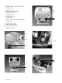
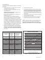
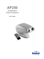
AP250
Automated
Chart Projector
User's Guide
©2011 Reichert, Inc. Reichert is a registered trademark of Reichert, Inc.
The information contained in this document was accurate at time of publication. Specifications subject to change without notice.
Reichert, Inc. reserves the right to make changes in the product described in this manual without notice and without incorporating those changes in any
products already sold.
Federal law restricts this device to sale by or on the order of a physician.
ISO 9001/13485 Certified – Reichert products are designed and manufactured under quality processes meeting
ISO 9001/13485 requirements.
No part of this publication may be reproduced, stored in a retrieval system, or transmitted in any form or by any means, electronic, mechanical, recording, or otherwise, without the prior written permission of Reichert, Inc.
2
13800-101-Rev. E
Contents
13800-101-Rev. E
Introduction
4
Safety Precautions
4
110V / 230V Operation
4
Package Contents
4
Accessories
4
Instrument Components
5
Installation
6
Alignment / Focusing
Remote Control Programming
Masking Options
7
Care and Maintenance
Slide Library
10
Letter Sizing Chart - Feet
12
Letter Sizing Chart - Meters
13
Technical Specifications
14
Symbol Information
14
Reichert Product Warranty
15
8
9
9
11
3
Introduction
Congratulations on your purchase of the AP250
Automated Projector.
In the field of subjective refraction, the AP250 is used for
measuring visual acuity.
This User’s Guide is designed as a training and reference
manual. We recommend you carefully read and follow the
steps in this guide to ensure optimum performance from
your new instrument.
Please retain this guide for future reference and to share
with other users.
For additional copies or assistance with this product,
contact the Reichert Customer Service Department.
Contact information is provided on the back of this
manual.
Safety Precautions
•
Except for changing the Halogen bulb and replacing
the fuses, any repair or service on the AP250 must be
performed only by authorized Reichert personnel.
•
Only qualified and trained personnel should operate
the AP250.
•
Training for operating personnel is the sole responsibility of the owner.
•
Plug the AP250 into a grounded electrical receptacle.
Do not remove cover. Otherwise, electrical shock can
occur. Do not remove or obstruct the grounded electrical connection or damage to the instrument or injury
to the operator may occur.
•
The line voltage setting on the AP250 power input
module should agree with the local line voltage.
Otherwise, damage to the instrument or injury to the
operator may occur.
•
Do not obstruct any ventilation slots.
•
Do not use the AP250 in the presence of flammable
anesthetics and volatile solvents such as alcohol,
benzine or similar agents.
•
Do not set-up the instrument in humid conditions.
Avoid dripping or splashing water near the instrument.
•
Use only accessories specified in this manual. If
you intend to use other accessories, consult an
authorized Reichert dealer or our Customer Service
Department.
•
Never look directly into the AP250's light source.
•
Disconnect the power cable prior to replacing the
AP250's Halogen bulb. Allow the lamp to cool-down
before touching or injury (burning) may occur.
4
110 V / 230 V Operation
To ensure proper operation, check the fuse voltage setting
on the power input module. The factory setting is 110 V.
If 230 V operation is desired,
remove the fuse holder and pull
out the white plasitc insert. Rotate
the insert so "230" appears in the
window when inserted in the fuse
holder. Remove the 500 mA fuses
and replace them with 250 mA
fuses. See page 14 for fuse types.
Install the fuse holder in
the power input connector.
Package Contents
Your new AP250 Automated Projector and accessories
were carefully packed and checked prior to shipment;
however, please check condition and contents upon
delivery. In addition to your AP250, this shipment
should include:
1 Spare Halogen Bulb
1 Power Cord
1 Dust Cover
1 Remote Control
2 Hexagon Keys (3 mm and 5 mm)
2 Spare Fuses 500 ma (110 V)
2 Spare Fuses 250 ma (230 V)
1 Pair of red/green spectacles
1 Pair of polarizing spectacles
4 AAA-sized batteries
1 Wall mount (2 pieces)
1 Screen
Accessories
13813 Flange Style Halogen Bulb ( pre S/N 10897-02)
13806 2-Pin Halogen Bulb (post S/N 10896-02)
13816 Remote Control
13814 Red / Green Spectacles
13815 Polarizing Spectacles
4013110 Dust Cover
11808 Projection Screen
12090 Table Mount
12091 Wall Mount
12092 Instrument Stand Mount
12096 Floor Stand Mount
13800-101-Rev. E
Instrument Components
1. Projector Head
7
2. Projection Lens
13
3. Remote Detection Window
4. Remote Control Unit
5. Mounting Bracket
6. Clamp-down Screw
8
9
7. Power Switch
8. Fuse Compartment with Voltage Indicator
9. Power Input
10. Halogen Bulb Housing
11. Chart Focusing Control
12. Distance Focusing Control
13. RS232C Serial Port
1
2
3
10
4
11
12
5
6
13800-101-Rev. E
5
Installation
The AP250 should be installed according to the following
procedures:
1. If using a wall mount, it is best to locate a wall stud
to support the projector’s weight.
2. The following distances are important in the set-up
of a refracting room:
REFRACTING DISTANCE (RD) The distance from
the patient’s eye to the screen.
PROJECTION DISTANCE (PD) The distance from
the slide to the screen.
LETTER HEIGHT (LH) The height of a 20/200
character should be equal to the refracting distance
times the tangent of 50 minutes of arc or .014545.
LH (inches) or (mm) = RD (inches) or (mm) x .014545
For example, a refracting distance of 240 inches (20
feet) will require a 20/200 height of 3.49 inches (240
inches x .014545 = 3.49 inches) or for a 4000 mm (4
m) refracting distance, you will require a letter height
of 58.18 mm (4000 mm x .014545 = 58.18 mm).
4. Install the projector screen.
5. If attaching the AP250 to a mount, loosen the clampdown screw (see page 5, #6) and insert the projector
mount onto the ball. Tighten screw, allowing for some
movement of the projector for final positioning. Fully
tighten the screw after final adjustment and alignment
of the system.
6. Make sure the voltage indicator number corresponds
with the available local mains.
7. Plug power cord into AC inlet and into a wall power
outlet. Set the power switch to the “ON” position.
NOTE: For proper operation, the remote typically needs
to be more than 5 ft (1.5 m) away from the projector.
Make sure no objects that could interrupt remote control
signals are located between remote control and projector.
3. Determine the refracting distance by measuring the
distance from the patient to the screen. Please refer
to Figures 1 and 2, below, which show combinations
of refracting and projection distances achievable with
this system.
PROJECTION RANGE LIST
Projection
Distance
6
Minimum
Refracting
Distance
Maximum
Refracting
Distance
ft m
ft m
ft m
10 3.0
7.4 2.3
11.6 3.5
11 3.3
8.2 2.5
12.7 3.9
12 3.6
8.9 2.7
13.0 4.2
13 3.9
9.6 2.9
15.0 4.6
14 4.2
10.4 3.2
16.2 4.9
15 4.5
11.1 3.4
17.3 5.3
16 4.8
11.8 3.6
18.5 5.6
17 5.1
12.6 3.8
19.6 6.0
18 5.4
13.3 4.1
20.8 6.3
19 5.7
14.0 4.3
21.9 6.7
20 6.0
14.8 4.5
23.1 7.0
21 6.4
15.5 4.7
24.3 7.4
22 6.7
16.2 4.9
25.4 7.7
23 7.0
17.0 5.2
26.6 8.1
24 7.3
17.7 5.4
27.7 8.4
25 7.6
18.4 5.6
28.9 8.8
26 7.9
19.2 5.8
30.0 9.2
Figure 1 - Projection Range List in feet and meters.
30
REFRACTING DISTANCE (ft)
PROJECTION RANGE GRAPH
25
20
Maximum
15
10
Minimum
5
10 11 12 13 14 15 16 17 18 19 20 21 22 23 24 25 26
PROJECTION DISTANCE (ft)
Figure 2 - Projection Range Graph in feet.
13800-101-Rev. E
Alignment / Focusing
The AP250 can be optimally focused at projection
distances between 10 ft (3 m) and 26.5 ft (8 m)
when the patient and projector are equidistant
from the projection screen.
2. Check the three-dimensional alignment of the
system. To optimize the alignment, it may be
necessary to angle the screen to direct light
towards the patient’s head. As a test, place a
mirror on the screen. The light should project
where the patient's head would be (see
Figure 3).
3. Adjust the image positioning on the screen. It
may be necessary to adjust the projector and
the screen. Secure projector by tightening
mounting screw.
4. Determine the proper letter size based on the
refracting distance used. Refer to the Letter
Sizing Charts at the end of this manual (pages
12 & 13).
Patient
Spot of
Light on
Wall
à
1. Project a 20/200 or 0.1 character onto the
key.
screen by pressing the
à
Mirror
Screen
AP250
Figure 3 - Checking three-dimensional alignment.
5. Attach Letter Sizing Chart to the screen.
6. Open the projector cover by removing the
hexagon screw under the front of the AP250.
7. Move the AP250's focusing controls (see page
5, # 11 & 12) until the 20/200 or .01 "Z" is in
sharp focus and fills the bracket on the Letter
Sizing Chart, as shown in Figure 3.
NOTE: To obtain longer refracting distances in
small rooms, a mirror or system of mirrors can
be used. A high quality front-surface mirror is
required. See Figure 4 as an example of a short
room with a full refracting distance of 20 feet.
NOTE: To prevent interference with the
operation of the Remote Control window, care
should be taken not to position any bright lights
directly toward the front of the AP250.
Patient
Mirror
Patient
Screen
Small
Mirror
AP250
Figure 4 - Using a mirror system in a small room.
WARNING: Proper setting of the focus
and distance controls requires that
the projector cover be open while the
instrument is plugged in and turned
on. Utilize only the distance and focus
controls while the cover is open.
Do not touch any other components under the cover or personal injury
may result.
13800-101-Rev. E
7
Remote Control
The AP250 is operated by an intuitive remote control that
is divided into various sections for ease of use (see figure
5). When the power switch on the back of the instrument
is in the ON position, slides can be projected by simply
pushing any button. The Lamp ON / OFF button can
be used to turn the lamp off at anytime. Otherwise, the
AP250 lamp shuts off automatically after 10 minutes of
non-use.
To use the AP250, simply press any button on the remote
control and the respective slide will be displayed. Red /
Green or Polarizing filters, and a variety of character / line
isolation masks can be applied to almost any chart
by pressing the appropriate buttons.
NOTE: The red indicator light flashes when pressing any remote control function, indicating that the control is functioning properly.
Indicator Light
Binocular Balance Test
Program Keys
Red/Green Test
Lamp On/Off
Children Charts
Illiterate Charts
Special Charts
Filters
Number Charts
Letter Charts
Eye Diagram
Masking Options
Figure 5 - Remote Control Unit
8
13800-101-Rev. E
CHANGING THE EMISSION CODE
Using the Programed Sequence
The codes of the projector and remote control are factory
set to 00. It is advisable to change the emission code of
the Remote Control unit if several projectors are used in
close proximity to one another to avoid interaction.
1. Press the Program Key (1 or 2).
To change the code, follow the steps below:
1. Open the battery compartment on the rear of the
remote control (see Figure 6). Use a small pointed
object to select a new switch position combination.
Sixteen combinations are possible.
2. Turn the power switch on the rear of the projector
to the OFF position. With the Remote Control
approximately 5 ft (1.5 m) away from the AP250's
Remote Detection Window, press the IN Program
Key while simultaneously switching on the projector.
You may require an assistant to help.
3. The AP250 will emit a short beep. Continue holding
the IN Program Key until you hear a longer beep.
The code setting is now complete.
PROGRAMMING SLIDE SEQUENCES
Switch UP = ON
1
2
3
2. Press the NEXT or BACK Key to display the slides
within your program sequence.
Interrupting a Slide Sequence at a Defined Point
1. Press the Program Key (1 or 2) you want to interrupt.
2. Press the IN Program Key.
3. Press the NEXT Program Key until the slide appears
that you want to conclude the sequence.
4. Press the OUT Program Key. The new slide
sequence is now stored.
Editing a Stored Slide Sequence
1. Press the Program Key (1 or 2) you want to edit.
2. Press the NEXT Program Key until the slide to be
changed appears on the screen.
3. Press the IN Program Key.
4. Press the new slide.
5. Confirm the new slide selection by pressing the
NEXT Program Key.
6. Press the OUT Program Key. The new slide
sequence is now stored.
MASKING OPTIONS
4
The AP250's masking options allow the operator to isolate
horizontal lines, vertical lines and individual charts. See
Figure 7 below for functions of masking buttons.
Switch Settings
APPLIES HORIZONTAL
Mask AND moves
mask Upwards
Battery
Compartment
APPLIES Vertical
Mask AND moves
mask to the Left
Figure 6 - Changing the Switch Settings
APPLIES Vertical
Mask AND moves
mask to the right
The AP250 can record two (2) custom slide sequences,
including masks. Follow the steps below to store, edit
and interrupt a programed slide sequence.
Storing a Slide Sequence
1. Press Program Key 1 or 2.
2. Press the IN Program Key.
3. Press the buttons of the desired slides, in the desired
order, followed by the NEXT button after each slide.
4. After pressing the final slide of the sequence, press
the OUT Program Key. The slide sequence is now
stored in the selected order as program 1 or 2.
13800-101-Rev. E
APPLIES horizontal
Top horizontal
Mask AND moveS
Mask or RETURN
mask downwards
TO full view
isolates individual
characters
Figure 7 - Functions of masking buttons
9
Care and Maintenance
WARNING: Risk of electric shock. Always
disconnect the power cord from the wall and the
instrument before performing any of the following
care and maintenance procedures.
CHANGING THE HALOGEN BULB
WARNING: Never touch a Halogen Bulb with
bare hands as fingerprints will shorten the bulb
life. Never remove a bulb that has recently been
in use as it will be very hot. Wait until it has
cooled and use gloves or a thick cloth when
handling any halogen bulb.
1. Open the top portion of the projector housing
by loosening the 3 mm hexagon screw located
underneath the front portion of the AP250 head.
2. Remove the cover from the bulb housing (page 5,
#10).
3. Remove the bulb by lightly pulling upwards on it.
CHANGING THE REMOTE CONTROL BATTERIES
1. Open the battery compartment on the rear side of the
remote control (see Figure 6).
2. Remove the batteries.
3. Insert four new AAA batteries and close battery
compartment.
CAUTION: Observe polarization markings on
the inside of the battery compartment and insert batteries accordingly.
CHANGING THE VOLTAGE / REPLACING FUSES
WARNING: Risk of electric shock. Always
disconnect the power before changing fuses.
CAUTION: Make sure the rating of the inserted fuses complies with the rating specified on the rating plate (see page 5, #8).
4. Position a new bulb over the pins and gently push
it down until fully seated.
1. Pull out the fuse holder in the fuse compartment
located on the backside of the AP250 (see page 5,
#8).
5. Replace the bulb housing cover.
2. Replace blown fuses.
6. Close the top portion of the projector housing and
tighten the cover screw.
3. Insert the fuse holder into the fuse compartment until
it snaps in.
NOTE: If illumination is not uniform, call your
Reichert dealer or our Customer Service department.
4. Reconnect the power cord and turn the projector on.
CLEANING
The exterior housing can be cleaned with a mild soap
solution applied to a clean, soft cloth.
Halogen Bulb
The projector lens and window for remote detection can
be cleaned with a soft, clean, optics-safe cloth.
To clean the remote control, wipe with a soft, clean,
dry cloth.
To clean the screen, wipe with a soft, clean, dry cloth.
CAUTION: The screen is very susceptible to scratches and fingerprints. Handle with care.
Figure 8 - Replacing the Halogen Bulb.
10
13800-101-Rev. E
Slide Library
Letter Charts
Number Charts
Illiterate Charts
Children Charts
Special Charts
Astigmatism
Red-Green
Cross Cylinder
Phoria
Phoria
with fixation
Minute Stereo
Fixation point
Vertical
Coincidence
Binocular
Balance
Vertical Line
Horizontal Line
Worth
13800-101-Rev. E
Eye Schematic
11
Letter Sizing Chart - Feet
REFRACTING DISTANCE
FEET
30
28
26
24
22
20
18
16
14
12
10
8
29
29
27
27
25
25
23
23
21
21
19
19
17
17
15
15
13
13
11
11
9
9
7
7
30
28
26
24
22
20
18
16
14
12
10
8
Figure 9 - Letter Sizing Chart in feet
12
13800-101-Rev. E
Letter Sizing Chart - Meters
REFRACTING DISTANCE
METERS
9.00
9.00
8.75
8.75
8.25
8.25
7.75
7.75
7.00
7.25
7.25
7.00
6.50
6.75
6.75
6.50
6.25
6.25
5.75
5.75
5.25
5.25
4.75
4.75
4.25
4.25
3.75
3.75
3.25
3.25
2.75
2.75
2.25
2.25
8.50
8.00
7.50
6.00
5.50
5.00
4.50
4.00
3.50
3.00
2.50
2.00
8.50
8.00
7.50
6.00
5.50
5.00
4.50
4.00
3.50
3.00
2.50
2.00
Figure 10 - Letter Sizing Chart in meters
13800-101-Rev. E
13
Technical Specifications
Projection Distance
Refraction Distance
Number Of Test Charts
Masks
10 Ft (3 M) To 26.5 Ft (8 M)
7.4 Ft (2.3 M) To 30 Ft (9.2 M)
33 Standard Test Charts
- Red/Green, Polarization, Single Horizontal Lines,
- Single Vertical, Single Letters And Single Numbers.
Tilt Range Of Projector
Automatic Switch-Off
Power Requirements
Line Voltage
Line Frequency
Line Fuse On 110V
Line Fuse On 230V
Projection Lamp
Grounding Wire
± 15°
After 10 Min. Without Operation.
110 V; 230 V; Margin ± 10%
50 To 60 Hz
500 Ma, Slow Blow/250 V
250 Ma, Slow Blow/250 V
12V/20W Halogen Bulb
Instrument To Be Connected Only To Proper
Outlets With Correct Ground Wire.
Protection Class
Degree Of Protection
Power Consumption
Dimensions (Head Only)
Height
Width
Depth
Color
Weight
1
IP 21
40 VA
7" (17.78 Cm)
8" (20.32)
13" (33.02)
White With Grey Accents
12 Lbs (5.4 Kg)
Symbol Information
The following symbols appear on the AP250:
CAUTION - An instruction that draws attention to the risk of damage to the product.
Consult accompanying documents.
Protective Earth (Ground)
WARNING - Risk of electric shock. Consult accompanying documents.
WARNING - An instruction that draws attention to the risk of injury or death.
Consult accompanying documents.
Alternating Current Power
Waste of Electrical and Electronic Equipment
14
Date of Manufacture
13800-101-Rev. E
Reichert Product Warranty
This product is warranted by Reichert, Inc. against defective material and workmanship under normal use for a period
of one year from the date of invoice to the original purchaser. (An authorized dealer shall not be considered an original
purchaser.) Under this warranty, Reichert’s sole obligation is to repair or replace the defective part or product at
Reichert’s discretion.
This warranty applies to new products and does not apply to a product that has been tampered with, altered in any way,
misused, damaged by accident or negligence, or which has had the serial number removed, altered or effaced. Nor
shall this warranty be extended to a product installed or operated in a manner not in accordance with the applicable
Reichert instruction manual, nor to a product which has been sold, serviced, installed or repaired other than by a
Reichert factory, Technical Service Center, or authorized Reichert Dealer.
Lamps, bulbs, charts, cards and other expendable items are not covered by this warranty.
All claims under this warranty must be in writing and directed to the Reichert factory, Technical Service Center, or
authorized instrument dealer making the original sale and must be accompanied by a copy of the purchaser’s invoice.
This warranty is in lieu of all other warranties implied or expressed. All implied warranties of merchantability or fitness for
a particular use are hereby disclaimed. No representative or other person is authorized to make any other obligations
for Reichert. Reichert shall not be liable for any special, incidental, or consequent damages for any negligence, breach
of warranty, strict liability or any other damages resulting from or relating to design, manufacture, sale, use or handling
of the product.
PATENT WARRANTY
If notified promptly in writing of any action brought against the purchaser based on a claim that the instrument infringes
a U.S. Patent, Reichert will defend such action at its expense and will pay costs and damages awarded in any such
action, provided that Reichert shall have sole control of the defense of any such action with information and assistance
(at Reichert’s expense) for such defense, and of all negotiation for the settlement and compromise thereof.
PRODUCT CHANGES
Reichert reserves the right to make changes in design or to make additions to or improvements in its products without
obligation to add such to products previously manufactured.
CLAIMS FOR SHORTAGES
We use extreme care in selection, checking, rechecking and packing to eliminate the possibility of error. If any shipping
errors are discovered:
1. Carefully go through the packing materials to be sure nothing was
inadvertently overlooked when the unit was unpacked.
2. Call the dealer you purchased the product from and report the
shortage. The materials are packed at the factory and none
should be missing if the box has never been opened.
3. Claims must be filed within 30 days of purchase.
CLAIMS FOR DAMAGES IN TRANSIT
Our shipping responsibility ceases with the safe delivery in good condition to the transportation company. Claims for
loss or damage in transit should be made promptly and directly to the transportation company.
If, upon delivery, the outside of the packing case shows evidence of rough handling or damage, the transportation
company’s agent should be requested to make a “Received in Bad Order” notation on the delivery receipt. If within 48
hours of delivery, concealed damage is noted upon unpacking the shipment and no exterior evidence of rough handling
is apparent, the transportation company should be requested to make out a “Bad Order” report. This procedure is
necessary in order for the dealer to maintain the right of recovery from the carrier.
13800-101-Rev. E
15
Reichert, Inc.
3362 Walden Ave
Depew, NY 14043
USA
Toll Free: 888-849-8955
Phone: 716-686-4500
Fax: 716-686-4545
Email: [email protected]
www.reichert.com
Reichert GmbH
Hubertstrasse 2
D-82229 Seefeld
Germany
Phone: +49-8152-993530
Fax: +49-8152-993535
ISO-9001 / 13485 Registered
May 2011
13800-101 Rev. E