1
SiENBE28-901
Service
Manual
Air Cooled Refrigeration
Condensing Unit
LRLEQ5AY1(E)
LRLEQ6AY1(E)
LRLEQ8AY1(E)
LRLEQ10AY1(E)
LRLEQ12AY1(E)
LRLEQ15AY1(E)
LRLEQ20AY1(E)
LRMEQ5AY1(E)
LRMEQ6AY1(E)
LRMEQ8AY1(E)
LRMEQ10AY1(E)
LRMEQ12AY1(E)
LRMEQ15AY1(E)
LRMEQ20AY1(E)
SiENBE28-901
Air Cooled Refrigeration
Condensing Unit
LRMEQ5AY1, 6AY1, 8AY1, 10AY1, 12AY1, 15AY1, 20AY1
LRLEQ5AY1, 6AY1, 8AY1, 10AY1, 12AY1, 15AY1, 20AY1
Air Cooled Refrigeration Condensing Unit 1
1
LRMEQ5AY1, 6AY1, 8AY1, 10AY1, 12AY1, 15AY1, 20AY1 1
LRLEQ5AY1, 6AY1, 8AY1, 10AY1, 12AY1, 15AY1, 20AY1 1
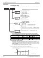
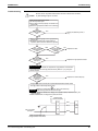
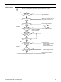
1. Introduction .............................................................................................2
2. Standard Specification ............................................................................7
2.1
2.2
2.3
2.4
2.5
2.6
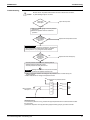
Standard Specification .............................................................................7
Set Values for Functional Components and Protection Devices............13
Operation Limits .....................................................................................14
Wiring Diagram.......................................................................................15
Piping Diagram.......................................................................................18
Description and Layout of Functional Parts and Piping Diagram ...........21
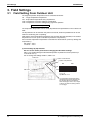
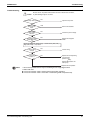
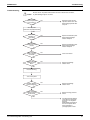
3. Field Settings ........................................................................................30
3.1 Field Setting From Outdoor Unit.............................................................30
4. Description of Functions and Operation................................................40
4.1 Operating Mode......................................................................................40
4.2 Outline of Functions ...............................................................................47
4.3 Detailed Description of Functions...........................................................48
5. Test Operation ......................................................................................57
5.1
5.2
5.3
5.4
5.5
5.6
Refrigerant Piping...................................................................................57
Field Wiring ............................................................................................63
Inspection and Pipe Insulation ...............................................................66
Checks after Work Completion...............................................................69
Additional Refrigerant Charge ................................................................69
Test Run.................................................................................................71
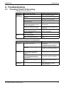
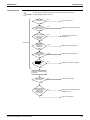
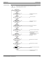
6. Troubleshooting ....................................................................................73
6.1
6.2
6.3
6.4
6.5
6.6
6.7
Checking Points at Servicing..................................................................73
List of Malfunction Codes .......................................................................76
Checking Malfunction Codes by LED Lamps on PCB............................77
Checking Malfunction Codes of the Condensing Unit ............................79
Troubleshooting by RAM Monitor...........................................................80
Flow Chart for Troubleshooting ..............................................................84
Maintenance.........................................................................................141
7. Appendix (Supplementary Information)...............................................149
7.1
7.2
7.3
7.4
Restriction Matter of Showcase............................................................149
Selection of Expansion Valve...............................................................149
Trouble Case with Present Machine (R-407C).....................................150
Option List ............................................................................................154
Air Cooled Refrigeration Condensing Unit
1
Introduction
SiENBE28-901
1. Introduction
Safety Precautions
Before performing design, construction, or maintenance, thoroughly read the "Safety
Precautions" and also the "Installation Manual" and "Operation Manual" that come with this
product.
Precautions are classified as " WARNING" or " CAUTION" for the purpose of this Section.
Items that mishandling highly potentially induces serious consequences such as death or serious
injury are specially described under " WARNING". Furthermore, even items described under
" CAUTION" potentially induce serious consequences depending on circumstances. All are
important items for safety and must be followed without fail.
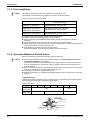
Pictograms
This symbol alerts you to precautions to be taken.
Sections under this symbol provide the specific descriptions of precautions.
This symbol alerts you to prohibited acts.
Sections under or in the vicinity of this symbol provide the specific
descriptions of prohibited acts.
This symbol alerts you to mandatory acts or instructions.
Sections under or in the vicinity of this symbol provide the specific
descriptions of instructions.
After the completion of construction or repair work, conduct test run on the equipment to check it
for any abnormalities, and also explain precautions for use of the equipment to customer.
<I. Precautions for Construction and Repair>
WARNING
(1) To overhaul the equipment,
be sure to turn OFF all power
supplies.
Not doing so will result in an electric
shock.
To repair the equipment or check for
circuits with power applied, pay utmost
attention not to touch any live part.
(2) If a refrigerant gas belches
during work, do not touch the
refrigerant gas.
Doing so will result in
frostbite.
(3) To remove a welded part
from the suction or discharge
pipe of compressor, remove
it in a well-ventilated area
after thoroughly discharging
a refrigerant gas.
gas or refrigerant oil to belch, thus
resulting in injury.
(4) If a refrigerant gas leaks
during work, ventilate the
working area.
If the refrigerant gas comes
into contact with a flame,
toxic gas will be generated.
(5) The electrical parts of
outdoor unit carry a high
voltage.
To repair these
parts, thoroughly
discharge
electricity from the
capacitor.
Not doing so will result in an electric
shock.
Not doing so will cause the refrigerant
2
Air Cooled Refrigeration Condensing Unit
SiENBE28-901
Introduction
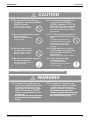
CAUTION
(6) Do not start or stop the air
conditioner using the POWER
SUPPLY switch.
Doing so may result in a
failure or water leakage.
(10) To clean the equipment, be
sure to set the POWER
SUPPLY switch to "OFF" to
turn OFF all power supplies.
Not doing so may result in injury
because the internal fan rotates at
high speeds.
(7) Do not repair electrical parts
with wet hand.
Doing so may result in an
electric shock.
(11) To dismount the equipment,
pay careful attention not to
tilt it.
Tilting the equipment may
cause water remaining in the
equipment to fall in drops,
thus wetting goods kept in
storage.
(12) Check whether or not the
refrigerating cycle part gets
hot, and then repair the
equipment.
(8) Do not wash the air
conditioner in water.
Doing so may result in an
electric shock or a fire.
Not doing so may result in a burn.
(9) Be sure to establish a ground
for the equipment.
(13) Use a welder in wellventilated areas.
Using the welder in an
enclosed room may result in
lack of oxygen.
Not doing so may result in
an electric shock.
<II. Precautions for Equipment after Construction and Repair>
WARNING
(14) To repair the equipment, be
sure to use parts listed in the
List of Service Parts for the
applicable model and proper
tools. Furthermore, NEVER
make any modification to the
equipment.
Not observing this warning will result
in an electric shock, heat generation,
or a fire.
Air Cooled Refrigeration Condensing Unit
(15) To install or relocate an air
conditioner, select a location
capable of supporting the
weight of the air conditioner.
The insufficient strength of the
location or improper installation of the
air conditioner will cause the unit to
drop, thus resulting in injury.
3
Introduction
SiENBE28-901
WARNING
(16) Conduct electrical works
according to information in
the "Electrical Equipment
Technical Standards",
"Internal Wiring
Regulations", and Installation
Manual, and further be sure
to use dedicated circuits.
Insufficient capacity of the
power supply circuit and
faulty electrical works will
result in an electric shock or
a fire.
(17) To make wirings between
indoor and outdoor units, use
specified wires to securely
connect them, and fix them so
that the external force of cables
will not be transmitted to
terminal connections.
Imperfect connections or fixing will
result in heat generation or a fire.
(18) To make wirings between
indoor and outdoor units or
for power supply, form wires
so that structures such as the
service lid will not be lifted,
and properly mount the lid.
Improperly mounting the lid will result
in heat generation of the terminal part,
an electric shock, or a fire.
(19) Do not cause damage to or
process the power supply cord.
Doing so will result in an
electric shock or a fire.
Putting heavy things on,
heating, or pulling the power
supply cord will result in
damage to it.
(20) Do not cause anything other
than the specified refrigerant
(e.g. air) to get mixed in the
refrigerant system.
Doing so will cause the refrigerant
system to have abnormally high
internal pressure, thus resulting in
damage to the equipment or bodily
injury.
(21) Should the equipment have
leakage of refrigerant gas,
locate leaking points, and then
repair them without fail.
Subsequently, refill the
equipment with a specified
quantity of refrigerant.
If no leaking points are located and
thereby repair work is to be
discontinued, perform pump-down
operation, and then close the service
valve. Not doing so will result in
refrigerant gas leakage.
The refrigerant gas itself is
harmless, but if it comes
into contact with a flame
from a fan heater, stove, or
stove burner, toxic gas will
be generated.
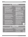
CAUTION
(22) A ground leakage circuit
breaker needs to be mounted.
Mounting no ground leakage circuit
breaker may result in an electric shock
or a fire.
4
(23) Do not install the equipment
in places with the potential
for leakage of flammable gas.
Should a flammable gas
leak to accumulate
around the equipment,
the gas may catch fire.
Air Cooled Refrigeration Condensing Unit
SiENBE28-901
Introduction
<III. Precautions after Construction and Repair>
WARNING
(24) Check power supply terminals
for deposition of dust or for
any loose terminals.
Deposition of dust on or
imperfect connections of
the terminals will result in
an electric shock or a fire.
Not doing so will result in an
electric shock, heat generation,
or a fire.
(26) Do not connect the power
supply cord halfway or with
many loads of other electrical
fittings on one electric outlet.
(25) Be sure to replace flawed or
deteriorated power supply
cord or lead wires.
Doing so will result in
an electric shock, heat
generation, or a fire.
CAUTION
(27) Check to be sure that the
mounting positions and
wiring conditions of parts as
well as the connections of
soldered parts and crimpstyle
terminals are all normal.
If any of these items is abnormal, an
electric shock, heat generation, or a
fire may result.
(28) If the installation base or
mounting frames are reduced
in strength due to corrosion,
replace them.
(30) After the completion of repair,
be sure to make measurement
of insulation resistance to
prove that it is not less than
1MΩ.
Insulation failures may result in an
electric shock.
(31) After the completion of repair,
be sure to check the indoor
unit for drainage.
Insufficient draining from the indoor
unit may result in the entry of water
into a room, thus wetting furniture
and household goods.
Not doing so may cause the equipment
to drop, thus resulting in injury.
(29) Check for the grounding
state. If the ground is in
an imperfect state,
rectify it.
Imperfect ground may
result in an electric shock.
Air Cooled Refrigeration Condensing Unit
5
Introduction
SiENBE28-901
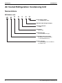
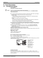
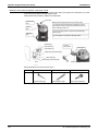
Air Cooled Refrigeration Condensing Unit
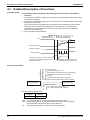
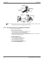
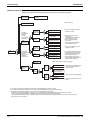
Nomenclature
Outdoor unit
LR
M
E
Q
5
A
Y1
Power supply symbol
Y1: 3φ 380-415V, 50Hz
Indicates major design category
Capacity indication
5: 5HP
Refrigerant
Q: R-410A
Compressor type
E: Intermediate INJ type
Temperature zone to be used
M: Medium temperature (MT)
L: Low temperature (LT)
Product category
L: Low temperature air conditioner
R: Outdoor unit
6
Air Cooled Refrigeration Condensing Unit
SiENBE28-901
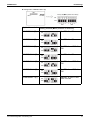
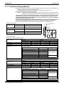
Standard Specification
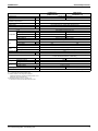
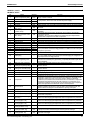
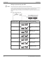
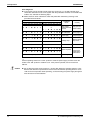
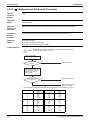
2. Standard Specification
2.1
Standard Specification
LRMEQ5AY1
[LRMEQ5AY1E]
Model 1
Power Supply
3 phase 50Hz 380-415V
Capacity 2
kW
Range of Suction Pressure Equivalent
Saturation Temperature
°C
Range of Outdoor Temperature
°C
Casing Color
12.2
-20~+10
-15~+43
mm
1680×635×765
Heat Exchanger
Cross fin coil
Type
Piston Displacement
Compressor Number of Revolutions
Motor Output × Number of Units
Hermetically sealed scroll type
m3/h
10.04
13.85
r.p.m
4740
6540
kW
2.3
Starting Method
Propeller fan
Motor Output
kW
Air Flow Rate
m3/min
0.35×1
95
Drive
Liquid Pipe
φ9.5 C1220T (Brazing connection)
Gas Pipe
φ19.1 C1220T (Brazing connection)
Mass
5.4
kg
Capacity Control
175
High Pressure Switch, Fan Driver Overload Protector, Overcurrent Relay,
Inverter Overload Protector, Fusible Plug
Safety Devices
Refrigerant
Oil
102
Direct drive
Receiver Volume
Refrigerant
3.2
Direct-on-line (Inverter system)
Type
Connecting
Pipes
14.4
Ivory white (5Y7.5/1) [Light camel (2.5Y6.5/1.5)]
Dimensions: (H×W×D)
Fan
LRMEQ6AY1
[LRMEQ6AY1E]
%
33~100
Refrigerant Name
Charge Volume
kg
5.2
Refrigerant Oil Name
Charge Volume
Operating Sound 3
24~100
R410A
DAPHNE FVC68D
L
dBA
Standard Accessories
1.7+2.5
54
56
Installation Manual, Operation Manual, Connection Pipes, Clamps
Notes:
H1 [ ] shows the anti-corrosion treatment type.
H2 Rated conditions of the refrigeration equipment :
Saturated temperature equivalent to suction pressure: -10°C
Outdoor air: 32°C, Suction SH: 10°C
H3 Measurement place: Front: 1m, Height: 1.5m
4 The minimum connection load with inside unit: 2.0kW
Air Cooled Refrigeration Condensing Unit
7
Standard Specification
SiENBE28-901
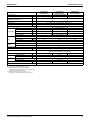
LRMEQ8AY1
[LRMEQ8AY1E]
Model 1
Power Supply
kW
Range of Suction Pressure Equivalent
Saturation Temperature
°C
Range of Outdoor Temperature
°C
18.6
21.8
-15~+43
Ivory white (5Y7.5/1) [Light camel (2.5Y6.5/1.5)]
Dimensions: (H×W×D)
mm
1680×930×765
Heat Exchanger
Cross fin coil
Type
Piston Displacement
Compressor Number of Revolutions
Motor Output × Number of Units
Hermetically sealed scroll type
m3/h
19.68
23.36
25.27
r.p.m
4320, 2900
6060, 2900
6960, 2900
kW
2.1+3.6
3.0+3.6
3.4+3.6
Starting Method
Direct-on-line (Inverter system)
Type
Propeller fan
Motor Output
kW
Air Flow Rate
m3/min
0.75×1
171
Drive
Liquid Pipe
φ9.5 C1220T (Brazing connection)
Gas Pipe
φ25.4 C1220T (Brazing connection)
Mass
Capacity Control
255
High Pressure Switch, Fan Driver Overload Protector, Overcurrent Relay,
Inverter Overload Protector, Fusible Plug
%
17~100
Refrigerant Name
Charge Volume
Charge Volume
14~100
13~100
R410A
kg
7.9
Refrigerant Oil Name
Operating Sound 3
191
8.1
kg
Safety Devices
Refrigerant
Oil
179
Direct drive
Receiver Volume
Refrigerant
24.4
-20~+10
Casing Color
Connecting
Pipes
LRMEQ12AY1
[LRMEQ12AY1E]
3 phase 50Hz 380-415V
Capacity 2
Fan
LRMEQ10AY1
[LRMEQ10AY1E]
DAPHNE FVC68D
L
dBA
Standard Accessories
1.7+2.1+3.0
57
59
61
Installation Manual, Operation Manual, Connection Pipes, Clamps
Notes:
H1 [ ] shows the anti-corrosion treatment type.
H2 Rated conditions of the refrigeration equipment :
Saturated temperature equivalent to suction pressure: -10°C
Outdoor air: 32°C, Suction SH: 10°C
H3 Measurement place: Front: 1m, Height: 1.5m
4 The minimum connection load with inside unit: 2.0kW
8
Air Cooled Refrigeration Condensing Unit
SiENBE28-901
Standard Specification
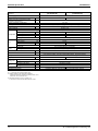
LRMEQ15AY1
[LRMEQ15AY1E]
Model 1
Power Supply
3 phase 50Hz 380-415V
Capacity 2
kW
Range of Suction Pressure Equivalent
Saturation Temperature
°C
Range of Outdoor Temperature
°C
Casing Color
32.2
37.0
-20~+10
-15~+43
Ivory white (5Y7.5/1) [Light camel (2.5Y6.5/1.5)]
Dimensions: (H×W×D)
mm
1680×1240×765
Heat Exchanger
Cross fin coil
Type
Piston Displacement
Compressor Number of Revolutions
Motor Output × Number of Units
Hermetically sealed scroll type
m3/h
30.00
35.80
r.p.m
5640, 2900
6960, 2900
kW
2.8+3.6+3.6
Starting Method
Propeller fan
Motor Output
kW
Air Flow Rate
m3/min
0.75×2
230
Drive
Connecting
Pipes
Liquid Pipe
φ12.7 C1220T (Brazing connection)
Gas Pipe
φ31.8 C1220T (Brazing connection)
Mass
12.1
kg
Capacity Control
355
High Pressure Switch, Fan Driver Overload Protector, Overcurrent Relay,
Inverter Overload Protector, Fusible Plug
Safety Devices
Refrigerant
Oil
240
Direct drive
Receiver Volume
Refrigerant
3.4+3.6+3.6
Direct-on-line (Inverter system)
Type
Fan
LRMEQ20AY1
[LRMEQ20AY1E]
%
10~100
Refrigerant Name
Charge Volume
kg
11.5
Refrigerant Oil Name
Charge Volume
Operating Sound 3
9~100
R410A
DAPHNE FVC68D
L
dBA
Standard Accessories
1.7+2.1+2.1+4.0
62
63
Installation Manual, Operation Manual, Connection Pipes, Clamps
Notes:
H1 [ ] shows the anti-corrosion treatment type.
H2 Rated conditions of the refrigeration equipment :
Saturated temperature equivalent to suction pressure: -10°C
Outdoor air: 32°C, Suction SH: 10°C
H3 Measurement place: Front: 1m, Height: 1.5m
4 The minimum connection load with inside unit: 2.0kW
Air Cooled Refrigeration Condensing Unit
9
Standard Specification
SiENBE28-901
LRLEQ5AY1
[LRLEQ5AY1E]
Model 1
Power Supply
3 phase 50Hz 380-415V
Capacity 2
kW
Range of Suction Pressure Equivalent
Saturation Temperature
°C
Range of Outdoor Temperature
°C
Casing Color
5.4
-45~-20
-15~+43
mm
1680×635×765
Heat Exchanger
Cross fin coil
Type
Piston Displacement
Compressor Number of Revolutions
Motor Output × Number of Units
Hermetically sealed scroll type
m3/h
10.04
13.85
r.p.m
4740
6540
kW
2.3
Starting Method
Propeller fan
Motor Output
kW
Air Flow Rate
m3/min
0.35×1
95
Drive
Liquid Pipe
φ9.5 C1220T (Brazing connection)
Gas Pipe
φ19.1 C1220T (Brazing connection)
Mass
5.4
kg
Capacity Control
175
High Pressure Switch, Fan Driver Overload Protector, Overcurrent Relay,
Inverter Overload Protector, Fusible Plug
Safety Devices
Refrigerant
Oil
102
Direct drive
Receiver Volume
Refrigerant
3.2
Direct-on-line (Inverter system)
Type
Connecting
Pipes
6.3
Ivory white (5Y7.5/1) [Light camel (2.5Y6.5/1.5)]
Dimensions: (H×W×D)
Fan
LRLEQ6AY1
[LRLEQ6AY1E]
%
33~100
Refrigerant Name
Charge Volume
kg
5.2
Refrigerant Oil Name
Charge Volume
Operating Sound 3
24~100
R410A
DAPHNE FVC68D
L
dBA
Standard Accessories
1.7+2.5
54
56
Installation Manual, Operation Manual, Connection Pipes, Clamps
Notes:
H1 [ ] shows the anti-corrosion treatment type.
H2 Rated conditions of the refrigeration equipment :
Saturated temperature equivalent to suction pressure: -35°C
Outdoor air: 32°C, Suction SH: 10°C
H3 Measurement place: Front: 1m, Height: 1.5m
4 The minimum connection load with inside unit: 1.6kW
10
Air Cooled Refrigeration Condensing Unit
SiENBE28-901
Standard Specification
LRLEQ8AY1
[LRLEQ8AY1E]
Model 1
Power Supply
kW
Range of Suction Pressure Equivalent
Saturation Temperature
°C
Range of Outdoor Temperature
°C
8.0
9.4
-15~+43
Ivory white (5Y7.5/1) [Light camel (2.5Y6.5/1.5)]
Dimensions: (H×W×D)
mm
1680×930×765
Heat Exchanger
Cross fin coil
Type
Piston Displacement
Compressor Number of Revolutions
Motor Output × Number of Units
Hermetically sealed scroll type
m3/h
19.68
23.36
25.27
r.p.m
4320, 2900
6060, 2900
6960, 2900
kW
2.1+3.6
3.0+3.6
3.4+3.6
Starting Method
Direct-on-line (Inverter system)
Type
Propeller fan
Motor Output
kW
Air Flow Rate
m3/min
0.75×1
171
Drive
Liquid Pipe
φ9.5 C1220T (Brazing connection)
Gas Pipe
φ25.4 C1220T (Brazing connection)
Mass
Capacity Control
255
High Pressure Switch, Fan Driver Overload Protector, Overcurrent Relay,
Inverter Overload Protector, Fusible Plug
%
17~100
Refrigerant Name
Charge Volume
Charge Volume
14~100
13~100
R410A
kg
7.9
Refrigerant Oil Name
Operating Sound 3
191
8.1
kg
Safety Devices
Refrigerant
Oil
179
Direct drive
Receiver Volume
Refrigerant
10.3
-45~-20
Casing Color
Connecting
Pipes
LRLEQ12AY1
[LRLEQ12AY1E]
3 phase 50Hz 380-415V
Capacity 2
Fan
LRLEQ10AY1
[LRLEQ10AY1E]
DAPHNE FVC68D
L
dBA
Standard Accessories
1.7+2.1+3.0
57
59
61
Installation Manual, Operation Manual, Connection Pipes, Clamps
Notes:
H1 [ ] shows the anti-corrosion treatment type.
H2 Rated conditions of the refrigeration equipment :
Saturated temperature equivalent to suction pressure: -35°C
Outdoor air: 32°C, Suction SH: 10°C
H3 Measurement place: Front: 1m, Height: 1.5m
4 The minimum connection load with inside unit: 1.6kW
Air Cooled Refrigeration Condensing Unit
11
Standard Specification
SiENBE28-901
LRLEQ15AY1
[LRLEQ15AY1E]
Model 1
Power Supply
3 phase 50Hz 380-415V
Capacity 2
kW
Range of Suction Pressure Equivalent
Saturation Temperature
°C
Range of Outdoor Temperature
°C
Casing Color
13.6
15.1
-45~-20
-15~+43
Ivory white (5Y7.5/1) [Light camel (2.5Y6.5/1.5)]
Dimensions: (H×W×D)
mm
1680×1240×765
Heat Exchanger
Cross fin coil
Type
Piston Displacement
Compressor Number of Revolutions
Motor Output × Number of Units
Hermetically sealed scroll type
m3/h
30.00
35.80
r.p.m
5640, 2900
6960, 2900
kW
2.8+3.6+3.6
Starting Method
Propeller fan
Motor Output
kW
Air Flow Rate
m3/min
0.75×2
230
Drive
Connecting
Pipes
Liquid Pipe
φ12.7 C1220T (Brazing connection)
Gas Pipe
φ31.8 C1220T (Brazing connection)
Mass
12.1
kg
Capacity Control
355
High Pressure Switch, Fan Driver Overload Protector, Overcurrent Relay,
Inverter Overload Protector, Fusible Plug
Safety Devices
Refrigerant
Oil
240
Direct drive
Receiver Volume
Refrigerant
3.4+3.6+3.6
Direct-on-line (Inverter system)
Type
Fan
LRLEQ20AY1
[LRLEQ20AY1E]
%
10~100
Refrigerant Name
Charge Volume
kg
11.5
Refrigerant Oil Name
Charge Volume
Operating Sound 3
9~100
R410A
DAPHNE FVC68D
L
dBA
Standard Accessories
1.7+2.1+2.1+4.0
62
63
Installation Manual, Operation Manual, Connection Pipes, Clamps
Notes:
H1 [ ] shows the anti-corrosion treatment type.
H2 Rated conditions of the refrigeration equipment :
Saturated temperature equivalent to suction pressure: -35°C
Outdoor air: 32°C, Suction SH: 10°C
H3 Measurement place: Front: 1m, Height: 1.5m
4 The minimum connection load with inside unit: 1.6kW
12
Air Cooled Refrigeration Condensing Unit
SiENBE28-901
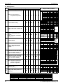
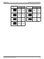
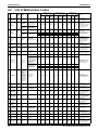
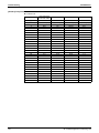
2.2
Standard Specification
Set Values for Functional Components and Protection
Devices
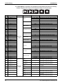
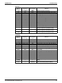
Component
Inverter
Compressor
STD1
STD2
Electric symbol
Type
Overcurrent protection device
Type
Overcurrent protection device
Type
Overcurrent protection device
Output
Fan motor
Overcurrent protection device
Output
Overcurrent protection device
PCB
M2C
M3C
M1F
M2F
A1P
PCB for compressor INV
A3P
JT17GFKTNYE@SB
—
13A
—
—
—
—
1.5A
3.0A
—
—
750W
—
—
3.0A
Standard:EB09058
Standard:PC0509-2
A7P
—
EB0292(C)
—
A9P
EC0729(A)-29
UKV-A023
UKV-A023
UKV-A024
DC12V, 0.26A
DC12V, 0.26A
DC12V, 0.26A
UKV-32D49
0~480pls
Coil
Y2E
(Gas)
UKV-A023
UKV-A023
UKV-A024
DC12V, 0.26A
DC12V, 0.26A
DC12V, 0.26A
UKV-18D20
Body
0~480pls
Coil
Y3E
(M1C)
Body
Coil
Four way valve
Body
Coil
Body
Solenoid valve
Coil
Body
Type
Set value
Type
High pressure
switch
Pressure protection device
Set value
Type
Set value
UKV-A023
UKV-A024
—
DC12V, 0.26A
DC12V, 0.26A
—
UKV-32D49
Y3S
Y2S
(M2C)
Y5S
(M3C)
S1PH
S2PH
S3PH
0~480pls
STF-G01AQ531A1
STF-G01AQ532A1
STF-0404G
STF-0713G
STF-G01AQ537A1
STF2011G
—
NEV-MOAJ562D1
NEV-MOAJ562D1
—
VPV-603D
VPV-603D
—
—
NEV-MOAJ562C1
—
—
VPV-603D
ACB-1TB29W
ACB-1TB28W
ACB-1TB27W
OFF 3.8
+0
-0.1
MPa
—
ON 2.85±0.15MPa
ACB-1TB27W
—
OFF 3.8
+0
-0.1
ACB-1TB27W
MPa
ON 2.85±0.15MPa
—
—
ACB-1TB27W
—
—
OFF 3.8 -0.1 MPa
ON 2.85±0.15MPa
+0
ACB-JB285
S4PH
DC5V ON: 2.96
+0
-0.1
MPa OFF: 2.16±0.15MPa
Low pressure sensor
S1NPL
150NH4-L2
200NH4-L2
200NH4-L2
High pressure sensor
S1NPH
150NH4-H4
150NH4-H4
200NH4-H4
Fusible plug
Thermistor
—
—
Type
Set value
EB0292(C)
EC0726(A)-9
Body
Electronic expansion valve
PC0511-2(A)
FN354-H-1(A)
—
Y1E
(Main)
PC0511-1(A)
—
EB0568(A)
A6P
Coil
13A
750W
—
A2P
JT17GFKTNYE@SB
350W
A8P
PCB for noise filter
PCB for earth leakage detection
14.7A
—
PC0511-3(A)
A5P
LRMEQ15AY1,20AY1
LRLEQ15AY1,20AY1
JT1GFDKTNYR@SB
A4P
PCB for operation input
PCB for current sensor
LRMEQ8AY1,10AY1,12AY1
LRLEQ8AY1,10AY1,12AY1
M1C
Main PCB
PCB for fan INV
LRMEQ5AY1,6AY1
LRLEQ5AY1,6AY1
—
Open: 70~75°C
Outdoor air thermistor
R1T
ST8603
Suction pipe thermistor
R2T
ST0602
Outdoor heat exchanger outlet
thermistor
R3T
ST8602A
Subcooling heat exchanger outlet
thermistor
R5T
ST0601
Subcooling heat exchanger inlet
thermistor
R6T
ST0601
R31T
Discharge pipe thermistor
ST0901
R32T
—
R33T
—
ST0901
—
Fuse (A1P)
F1U, F2U
250VAC 3.15A, Class T
Fuse
F3U, F4U
250VAC 1.0A, Class T
S1S
AR22PR-311B Z9
Operation switch
Air Cooled Refrigeration Condensing Unit
ST0901
13
Standard Specification
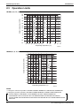
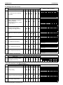
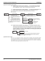
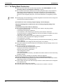
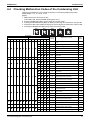
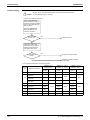
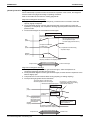
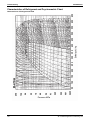
2.3
SiENBE28-901
Operation Limits
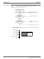
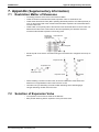
LRLEQ5, 6, 8, 10, 12, 15, 20AY1(E)
43
40
30
25
20
15
10
5
0
Range for pull down operation
Range for continuous operation
Outdoor temperature (°CDB)
35
-5
-10
-15
-45 -40 -35 -30 -25 -20 -15
5
10
30
35
40
Evaporating temperature (°C)
4D064913
LRMEQ5, 6, 8, 10, 12, 15, 20AY1(E)
43
40
Range for pull down
operation
30
Range for continuous operation
Outdoor temperature (°CDB)
35
25
20
15
10
5
0
-5
-10
-15
-20 -15 -10
-5
0
5
10
30
35
40
Evaporating temperature (°C)
4D064914
NOTES
∗1. “Range for continuous operation” SHOWS POSSIBLE RANGE OF CONTINUOUS OPERATION.
∗2. “Range for pull down operation” SHOWS POSSIBLE RANGE OF SHORT-TIME OPERATION.
• DO NOT SELECT THE MODEL IN THE RANGE FOR PULL DOWN OPERATION.
• TO BE MORE THAN 3°C/HOUR THAT THE TEMPERATURE OF INDOOR UNIT DROPS.
DO NOT OPEN THE DOOR AND DO NOT ENTER THE GOODS IN PULL DOWN OPERATION AS
MUCH AS.
14
Air Cooled Refrigeration Condensing Unit
X1A
X2A
RY1
X3A
NOTE)10
A9P
BLK
RED
L1 L2 L3 N
WHT
T2A
N=1
: TERMINAL STRIP
3.
X400A
A2P
M1C
MS
3~
V
U
R50 R59
C66 C63
: CONNECTOR
Z3C
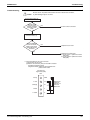
N=5
WHT
P2
L1R
WHT
P1
A3P
K4M
W
Z10C
N=4
GRN
GRN
X5A
P3
N3
t°
R1T
BLK
RED
X1A
Z5C
N=1
F1U
P1
Z2C
N=1
X1A
X3A
X5A
A4P
Z4C
N=1
X4A
X6A
X61A
X402A
BLK
BLU
RED
M1F
MS
3~
5
5
F2U
F1U
X2A
X4A
X2A
V1R
R10
N1
X20A
X28A
X1A
A1P
: PROTECTIVE EARTH (SCREW)
X111A
X41A
: TERMINAL
X11A
V1R
R95
K1R
V2R
PS
X1A
X10A
K2M
X403A
C1
X401A
F400U
K3R
Z1F
WHT
CAPACITOR
REFER TO TECHNICAL GUIDE FOR THE OPERATION TIMING DIAGRAM.
10. RY1 POINT CONTACT IS OPEN BEFORE TURNING ON POWER SUPPLY.
MAGNETIC RELAY
MAGNETIC CONTACTOR (M1C)
K2M, K4M
PILOTLAMP (SERVICE MONITOR-GREEN)
K1R, K3R
HAP
H1P~8P
PILOTLAMP (SERVICE MONITOR-ORANGE)
[H2P] MALFUNCTION DETECTION --- LIGHT UP
FUSE (T, 6.3A, 250V) (A2P)
F400U
DIP SWITCH (A1P)
CAPACITOR (A3P)
7. HOW TO USE BS1~5 AND DS1 AND DS2 SWITCH, REFER TO "SERVICE PRECAUTION" LABEL ON EL. COMPO. BOX COVER.
DS1, DS2
C63, C66
C1
R95
R1T
OFF
ON
1234
DS2
R5T
t°
X30A
PRESSURE SENSOR (HIGH)
MAGNETIC RELAY (A9P)
THERMISTOR (HEAT EX, OF SUBCOOL INLET)
THERMISTOR (HEAT EX, OF SUBCOOL OUTLET)
THERMISTOR (HEAT EXC, DEICER)
THERMISTOR (M1C DISCHARGE)
THERMISTOR (SUCTION)
THERMISTOR (FIN) (A3P)
THERMISTOR (AIR) (A1P)
RESISTOR (CURRENT LIMITING)
RESISTOR (A3P)
RESISTOR (CURRENT SENSOR) (A4P)
PHASE REVERSAL DETECT CIRCUIT
SWITCHING POWER SUPPLY (A1P, A3P)
MOTOR (FAN)
MOTOR (COMPRESSOR)
REACTOR (A3P)
Z1F
R1T
S4PH
M
Y2E
M
Y1E
W
X2A
X1A
OUTER SHELL
M1C
A2P
A3P
X1M
S1S
X3M
A4P
L1R
A1P
3D059917C
NOISE FILTER (WITH SURGE ABSORBER) (A2P)
NOISE FILTER (FERRITE CORE)
SOLENOID VALVE (4 WAY VALVE)
ELECTRONIC EXPANSION VALVE (GAS)
ELECTRONIC EXPANSION VALVE (MAIN)
TERMINAL STRIP (REMOTE SWITCH)
TERMINAL STRIP
TERMINAL STRIP (OPERATION) (A5P)
TERMINAL STRIP (POWER SUPPLY)
CONNECTOR (M1F)
DIODE BRIDGE (A3P)
POWER MODULE (A3P, A4P)
SAFETY DEVICES INPUT
CURRENT SENSOR (A9P)
PRESSURE SWITCH (HIGH)
OPERATION SWITCH (REMOTE / OFF / ON)
PRESSURE SWITCH (HIGH)
(BACK)
(FRONT)
X2M
A5P
CONTROL, BOX
CONTROL, BOX
A9P
M1F
V
LAYOUT OF M1C, M1F
U
TERMINAL OF M1C
PRESSURE SENSOR (LOW)
5
WHT BLK
5
S1NPH
S1NPL
P<
t°
Z1C~5C, Z10C
Y3S
Y2E
Y1E
X3M
X2M
X1M
X1M
X1A, X2A
V2R
V1R
V1CP
T2A
S4PH
S1S
S1PH
S1NPL
R6T
t°
BLK
X21A
X32A
X31A
X18A
X36A
X22A
MAGNETIC RELAY (OPERATING OUTPUT)
MAGNETIC RELAY (WARNING OUTPUT)
MAGNETIC RELAY (Y3S)
MAGNETIC RELAY (CAUTION OUTPUT)
SWITCH
NOTE)4
R3T
R2T
X29A
COMPONENT LEAD WIER.
R31T
X3M
1
2
HAP
CIRCUIT BOARD.
IS CONNECTOR COLOR FOR COMPONENT.
IS DISCRIMINATION COLOR FOR
t°
S1NPH
RY1
R6T
R5T
R3T
R31T
R2T
R1T
1234
DS1
t°
R50, R59
R10
OFF
ON
BS1 BS2 BS3 BS4 BS5
H1P H2P H3P H4P H5P H6P H7P H8P
IS CONNECTOR COLOR FOR PRINTED
PS
t°
Q1RP
PS
M1F
M1C
PRINTED CIRCUIT BOARD (EARTH LEAKAGE DETECTOR)
PUSH BUTTON SWITCH
(MODE, SET, RETURN, TEST, RESET)
A9P
BS1~5
6. BE NOTED THAT THE CAPACITY OF CONTACT IS AC220~240V, 0.5A. (OPERATING OUTPUT)
9. COLORS BLK: BLACK RED: RED BLU: BLUE WHT: WHITE GRN: GREEN.
K6R
L1R
PRINTED CIRCUIT BOARD (ABC I / P)
K10R
PRINTED CIRCUIT BOARD (FAN)
A5P
FUSE (8A, DC650V) (A4P)
8. WHEN OPERATING, DON'T SHORTCIRCUIT THE PROTECTION DEVICE (S1PH).
1
K3R
2
ON
A4P
FUSE (T, 3.15A, 250V) (A1P)
5. BE NOTED THAT THE CAPACITY OF CONTACT IS AC220~240V, 0.5A. (TOTAL OF CAUTION OUTPUT, WARNING OUTPUT)
OFF
PRINTED CIRCUIT BOARD (INV)
3
REMOTE
4
S1S
C
A3P
B
X2M
PRINTED CIRCUIT BOARD (MAIN)
A
FUSE (T, 1.0A, 250V)
(FOR THE REMOTE SWITCH, USE NON-VOLTAGE CONTACT FOR MICROCURRENT (NOT MORE THAN 1mA DC12V))
THE POINT OF CONTACT OF THE INPUT MUST USE THE ONE FOR A SLIGHT CURRENT.
P1 P2
PRINTED CIRCUIT BOARD (NOISE FILTER) K5R
X1M
C1 W1
F4U
X14A
A2P
X1A
A5P
C
X10A
CAUTION WARNING OPERATING
OUTPUT OUTPUT
OUTPUT
NOTE)5
NOTE)5
NOTE)6
F3U
Y3S
X9A
K10R
A1P
X66A
X7A
K3R
F3U, F4U
X4A
X3A
X2A
K5R
F1U, F2U
V1CP
S1PH
P<
Q1RP
K6R
F1U
4. AT THE TIME OF FACTORY SHIPMENT, SETTING OF "OFF". WHEN OPERATING, SETTING OF "ON" OR "REMOTE".
: FIELD WIRING.
2.
ONLY TO THE OUTDOOR UNIT.
NOTES)
1. THIS WIRING DIAGRAM IS APPLIED
X1M
RED
RED
BLU
RED
Z1C N=1
WHT
WHT
BLU
POWER SUPPLY
BLK
BLK
BLK
Y1: 380-415V 3N~50Hz
RED
Air Cooled Refrigeration Condensing Unit
WHT
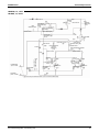
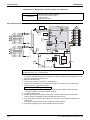
2.4
BLK
L1 L2 L3 N
SiENBE28-901
Standard Specification
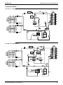
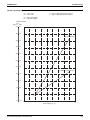
Wiring Diagram
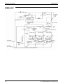
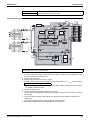
LRLEQ5A, 6AY1(E)
LRMEQ5A, 6AY1(E)
15
X3A
Z7C
N=5
U
M2C
M
3~
V
W
U
T
W
S
V
R
K2M
BLK
A6P
T1A
X1A
: TERMINAL STRIP
3.
M1C
MS
3~
W
V
U
R50 R59
C66 C63
: CONNECTOR
Z3C
N=5
WHT
P2
GRN C1
X403A
t°
RED
BLK
X1A
Z5C
N=1
X1A
X3A
X5A
A4P
Z4C
N=1
X4A
X6A
X61A
X402A
F1U
P1
Z2C
N=1
BLK
BLU
RED
MS
3~
M1F
5
5
F2U
F1U
X2A
X4A
X2A
V1R
R10
N1
X20A
X28A
X26A
X1A
A1P
: PROTECTIVE EARTH (SCREW)
X111A
X41A
X5A
P3
N3
X1A
PS
R1T
: TERMINAL
X11A
V1R
R95
K1R
V2R
K2M
X10A
X401A
K3R
F400U
Z1F
GRN
A2
K2M
A
B
3
REMOTE
4
S1S
C
1234
DS2
R3T
t°
R5T
t°
Q1RP
PS
PHASE REVERSAL DETECT CIRCUIT
SWITCHING POWER SUPPLY (A1P, A3P)
MAGNETIC CONTACTOR (M2C)
K2M
S1NPH
RY1
R6T
R5T
Z1C~7C, Z10C
MAGNETIC RELAY
THERMSITOR (HEAT EX, OF SUBCOOL OUTLET)
PILOTLAMP (SERVICE MONITOR-GREEN)
R3T
MAGNETIC CONTACTOR (M1C)
Y3S
THERMSITOR (HEAT EXC, DEICER)
R31T, R32T
[H2]MALFUNCTION DETECTION---LIGHT UP
Y3E
Y2S
PRESSURE SENSOR (HIGH)
MAGNETIC RELAY (A9P)
THERMSITOR (HEAT EX, OF SUBCOOL INLET) Z1F
THERMSITOR (SUCTION)
Y2E
THERMSITOR (M1C, M2C DISCHARGE)
R2T
PILOTLAMP (SERVICE MONITOR-ORANGE)
THERMSITOR (FIN) (A3P)
R1T
FUSE (T, 6.3A, 250V) (A2P)
Y1E
X3M
X2M
X1M
X1M
X1A, X2A
H1P~8P
THERMSITOR (AIR) (A1P)
RESISTOR (CURRENT LIMITING)
RESISTOR (A3P)
RESISTOR (CURRENT SENSOR) (A4P, A5P)
F400U
R1T
R95
R50, R59
R10
V
W
M
Y3E
M
Y2E
M
Y1E
X2A
CONTROL, BOX
A2P
A3P
A6P
A4P
L1R
X3M
3D059918C
NOISE FILTER (WITH SURGE ABSORBER) (A2P)
NOISE FILTER (FERRITE CORE)
SOLENOID VALVE (4 WAY VALVE)
SOLENOID VALVE (M2C)
ELECTRONIC EXPANSION VALVE (M1C)
ELECTRONIC EXPANSION VALVE (GAS)
ELECTRONIC EXPANSION VALVE (MAIN)
TERMINAL STRIP (REMOTE SWITCH)
TERMINAL STRIP
TERMINAL STRIP (OPERATION) (A5P)
TERMINAL STRIP (POWER SUPPLY)
CONNECTOR (M1F)
DIODE BRIDGE (A3P)
POWER MODULE (A3P, A4P)
SAFETY DEVICES INPUT
CURRENT SENSOR (A9P)
CURRENT SENSOR (A6P)
PRESSURE SWITCH (HIGH)
OPERATION SWITCH (REMOTE/OFF/ON)
PRESSURE SWITCH (HIGH)
A1P
K2M
(BACK)
(FRONT)
X1M
X2M
S1S
A5P
OUTER SHELL
M2C
M1C
CONTROL. BOX
A9P
X1A
M1F
LAYOUT OF M1C, M2C, M1F
U
TERMINAL OF M1C, M2C
PRESSURE SENSOR (LOW)
5
WHT BLU
5
WHT BLK
5
S1NPH
FUSE (T, 1.0A, 250V)
FUSE (T, 3.15A, 250V) (A1P)
FUSE (8A, DC650V) (A4P)
DIP SWITCH (A1P)
CAPACITOR (A3P)
CAPACITOR
V2R
V1R
V1CP
T2A
T1A
S4PH
S1S
R1T
S4PH
S1NPL
S1PH, S2PH
S1NPL
t°
P<
F3U, F4U
F1U, F2U
F1U
DS1, DS2
C63, C66
C1
MOTOR (FAN)
M1C, M2C
M1F
REACTOR (A3P)
L1R
MAGNETIC RELAY (OPERATING OUTPUT)
MOTOR (COMPRESSOR)
K10R
(MODE, SET, RETURN, TEST, RESET)
R6T
t°
X23A
BLU
BLK
X21A
X32A
X31A
X18A
X22A
MAGNETIC RELAY (WARNING OUTPUT)
MAGNETIC RELAY (Y3S)
MAGNETIC RELAY (Y2S)
MAGNETIC RELAY (CAUTION OUTPUT)
MAGNETIC RELAY (K2M)
SWITCH
NOTE)4
R2T
t°
X30A
PUSH BUTTON SWITCH
BS1~5
HAP
IS CONNECTOR COLOR FOR COMPONENT.
IS DISCRIMINATION COLOR FOR
COMPONENT LEAD WIRE.
PRINTED CIRCUIT BOARD (EARTH LEAKAGE DETECTOR)
HAP
9. COLORS BLK:BLACK RED:RED BLU:BLUE WHT:WHITE CRN:GREEN.
OFF
ON
IS CONNECTOR COLOR FOR
PRINTED CIRCUIT
1234
DS1
BS1 BS2 BS3 BS4 BS5
X36A
H1P H2P H3P H4P H5P H6P H7P H8P
PRINTED CIRCUIT BOARD (CURRENT SENSOR)
K6R
K5R
K4R
K3R
K1R
X3M
1
2
R32T
t°
X29A
ON
OFF
PS
A9P
PRINTED CIRCUIT BOARD (ABC I/P)
PRINTED CIRCUIT BOARD (FAN)
PRINTED CIRCUIT BOARD (INV)
PRINTED CIRCUIT BOARD (NOISE FILTER)
2
t°
R31T
ON
1
X2M
OFF
PRINTED CIRCUIT BOARD (MAIN)
X1M
OPERATING
OUTPUT
NOTE)6
P1 P2
F4U
X14A
K10R
A6P
A5P
A4P
A3P
A2P
A1P
X1A
C1 W1
X10A
CAUTION WARNING
OUTPUT OUTPUT
NOTE)5 NOTE)5
C
F3U
Y3S
X9A
K2M, K4M
X66A
A5P
Y2S
X8A
K4R
K1R, K3R
X5A
K1R
K3R
X7A
K5R
REFER TO TECHNICAL GUIDE FOR THE OPERATION TIMING DIAGRAM.
WHT
RED
X4A
X3A
X2A
K6R
10. RY1 POINT CONTACT IS OPEN BEFORE TURNING ON POWER SUPPLY.
8. WHEN OPERATING, DON'T SHORTCIRCUIT THE PROTECTION DEVICE (S1PH, S2PH).
7. HOW TO USE BS1~5 AND DS1 AND DS2 SWITCH, REFER TO "SERVICE PRECAUTION" LABEL ON EL. COMPO. BOX COVER.
6. BE NOTED THAT THE CAPACITY OF CONTACT IS AC220~240V, 0.5A. (OPERATING OUTPUT)
P<
P<
Q1RP
V1CP
S2PH
S1PH
A1
5. BE NOTED THAT THE CAPACITY OF CONTACT IS AC220~240V, 0.5A. (TOTAL OF CAUTION OUTPUT, WARNING OUTPUT)
NON-VOLTAGE CONTACT FOR MICROCURRENT (NOT MORE THAN 1mA DC12V))
POINT OF CONTACT OF THE INPUT MUST USE THE ONE FOR A SLIGHT CURRENT. (FOR THE REMOTE SWITCH, USE
4. AT THE TIME OF FACTORY SHIPMENT, SETTING OF "OFF". WHEN OPERATING, SETTING OF "ON" OR "REMOTE". THE
: FIELD WIRING.
2.
TO THE OUTDOOR UNIT.
WHT
P1
A3P
K4M
T2A
N=1 Z1C
N=1
X400A
L1R
A2P
Z6C
N=1
1. THIS WIRING DIAGRAM IS APPLIED ONLY
NOTES)
NOTE) 10
X2A
RY1
X1A
N BLU
N
A9P
L3
L3
Z10C
N=4
WHT
WHT
L2
RED
L2
RED
BLU
POWER SUPPLY
Y1: 380-415V 3N~50Hz
BLK
RED
WHT
RED
WHT
BLK
BLK
WHT
BLK
RED
RED
L1
BLK
X1M
WHT
16
L1
Standard Specification
SiENBE28-901
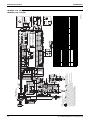
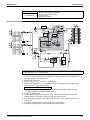
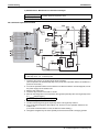
LRLEQ8A, 10A, 12AY1(E)
LRMEQ8A, 10A, 12AY1(E)
Air Cooled Refrigeration Condensing Unit
W
: TERMINAL STRIP
TO THE OUTDOOR UNIT.
: FIELD WIRING.
P1
A3P
: CONNECTOR
M1C
MS
3~
W
V
R50 R59
C66 C63
U
WHT
P2
L1R
K4M
X400A
Z1C
N=1
K3R
Z3C
N=5
P3
N3
t°
X111A
X41A
X5A
PS
X1A
X403A
BLU
:TERMINAL
X11A
V1R
R95
K1R
V2R
K2M
X10A
X401A
WHT
R1T
GRN
F400U
Z1F
C1
BLK
RED
F1U
P2 N1
Z2C
N=1
M1F
MS
3~
N2
X2A
X3A
5
5
X20A
X28A
X25A
X26A
X2A
X4A
X51A
RED
WHT
F1U
A5P
4
3
REMOTE
S1S
OFF
C
2
PUSH BUTTON SWITCH
CAPACITOR (A3P)
R6T
t°
MAGNETIC RELAY (Y2S)
RESISTOR (CURRENT LIMITING)
RESISTOR (A3P)
THERMISTOR (M1C~3C DISCHARGE)
THERMISTOR (HEAT EXC, DEICER)
R2T
R31~33T
R3T
[H2P] MALFUNCTION DETECTION---LIGHT UP
MAGNETIC CONTACTOR (M1C)
MAGNETIC CONTACTOR (M2C, M3C)
MAGNETIC RELAY (K2M, K3M)
K2M, K3M
K1R, K2R
S1NPL
S1NPH
RY1
R6T
PILOTLAMP (SERVICE MONITOR-GREEN) R5T
MAGNETIC RELAY
K2M, K4M
PRESSURE SENSOR (LOW)
PRESSURE SENSOR (HIGH)
MAGNETIC RELAY (A9P)
R1T
Y5S
Y3S
Y2S
Y3E
Y2E
Y1E
X3M
X2M
X1M
X1M
X105A
X1A~4A
V2R
V1R
V1CP
T2A
T1A
S1S
S4PH
Z1F
5
V
W
M2F
A2P
A3P
X1M
X2A X4A
X1A X3A
A9P
(BACK)
X3M
A5P
3D063035B
NOISE FILTER (WITH SURGE ABSORBER) (A2P)
NOISE FILTER (FERRITE CORE)
SOLENOID VALVE (M3C)
SOLENOID VALVE (4 WAY VALVE)
SOLENOID VALVE (M2C)
ELECTRONIC EXPANSION VALVE (M1C)
ELECTRONIC EXPANSION VALVE (GAS)
ELECTRONIC EXPANSION VALVE (MAIN)
TERMINAL STRIP (REMOTE SWITCH)
TERMINAL STRIP
TERMINAL STRIP (OPERATION) (A5P)
TERMINAL STRIP (POWER SUPPLY)
CONNECTOR (S3PH)
CONNECTOR (M1F, M2F)
DIODE BRIDGE (A3P)
POWER MODULE (A3P, A4P, A8P)
SAFETY DEVICES INPUT
CURRENT SENSOR (A9P)
CURRENT SENSOR (A6P, A7P)
OPERATION SWITCH (REMOTE/OFF/ON)
PRESSURE SWITCH (HIGH)
A8P
A4P
L1R
K3M
A7P
A1P
(FRONT)
K2M
A6P
X2M
S1S
CONTROL. BOX
OUTER SHELL
M3C
M2C
M1C
CONTROL, BOX
PRESSURE SWITCH (HIGH)
M
Y3E
M
Y2E
M
M1F
LAYOUT OF M1C~M3C, M1F, M2F
U
TERMINAL OF M1C~M3C
Y1E
WHT BLU
5
WHT BLK
5
S1NPH
S1NPL
THERMISTOR (HEAT EX, OF SUBCOOL INLET) Z1C~10C
THERMISTOR (HEAT EX, OF SUBCOOL OUTLET)
THERMISTOR (SUCTION)
THERMISTOR (FIN) (A3P)
PILOTLAMP (SERVICE MONITOR-ORANGE)
R1T
H1P~8P
THERMISTOR (AIR) (A1P)
t°
P< S4PH
S1PH~3PH
BLU
RESISTOR (CURRENT SENSOR) (A4P, A8P)
PHASE REVERSAL DETECT CIRCUIT
SWITCHING POWER SUPPLY (A1P, A3P)
MOTOR (FAN)
MOTOR (COMPRESSOR)
REACTOR (A3P)
MAGNETIC RELAY (Y5S)
MAGNETIC RELAY (OPERATING OUTPUT)
MAGNETIC RELAY (WARNING OUTPUT)
MAGNETIC RELAY (Y3S)
FUSE (T, 6.3A, 250V) (A2P)
K1R,K3R
9. COLORS BLK:BLACK RED:RED BLU:BLUE WHT:WHITE GRN:GREEN.
R5T
t°
X23A
MAGNETIC RELAY (CAUTION OUTPUT)
SWITCH
R3T
t°
X30A
BLK
X21A
X32A
X31A
X18A
X22A
F400U
R1T
R95
R50, R59
R10
Q1RP
PS
M1F, M2F
M1C~3C
L1R
K11R
K10R
K6R
1234
DS2
FUSE (T, 1.0A, 250V)
FUSE (T, 3.15A, 250V) (A1P)
FUSE (8A, DC650V) (A4P, A8P)
DIP SWITCH (A1P)
K4R
K5R
OFF
ON
F3U, F4U
F1U, F2U
F1U
DS1, DS2
C63, C66
CAPACITOR
(MODE, SET, RETURN, TEST, RESET)
PRINTED CIRCUIT BOARD (EARTH LEAKAGE DETECTOR)
C1
PRINTED CIRCUIT BOARD (CURRENT SENSOR)
A6P, A7P
BS1~5
A5P
A9P
PRINTED CIRCUIT BOARD (FAN)
PRINTED CIRCUIT BOARD (ABC I/P)
A4P, A8P
PRINTED CIRCUIT BOARD (NOISE FILTER)
K3R
R2T
R33T
R32T
R31T
NOTE)4
t°
t°
X3M
1
2
1234
DS1
IS CONNECTOR COLOR FOR COMPONENT.
IS DISCRIMINATION COLOR FOR
COMPONENT LEAD WIRE.
t°
ON
1
PRINTED CIRCUIT BOARD (MAIN)
B
X29A
OFF
ON
HAP
X36A
H5P H6P H7P H8P
BS1 BS2 BS3 BS4 BS5
H1P H2P H3P H4P
IS CONNECTOR COLOR FOR PRINTED
CIRCUIT BOARD.
PS
t°
P1 P2 X2M
PRINTED CIRCUIT BOARD (INV)
A
X1M
C1 W1
Y5S
X15A
X14A
A3P
A2P
A1P
X1A
C
F4U
CAUTION WARNING OPERATING
OUTPUT OUTPUT
OUTPUT
NOTE)5
NOTE)5
NOTE)6
F3U
Y3S
X10A
X9A
HAP
5
WHT
X4A
RED
X4A
X6A
X66A
Y2S
X8A
X7A
REFER TO TECHNICAL GUIDE FOR THE OPERATION TIMING DIAGRAM.
M2F
MS
3~
5
X4A
X3A
X2A
K2R
X5A
K1R
X2A
V1R
R10
N1
RED
WHT
WHT
RED
V1CP
X105A
P<
P<
Q1RP
10. RY1 POINT CONTACT IS OPEN BEFORE TURNING ON POWER SUPPLY.
8. WHEN OPERATING, DON'T SHORTCIRCUIT THE PROTECTION DEVICE (S1PH~S3PH).
7. HOW TO USE BS1~5, DS1 AND DS2 SWITCH, REFER TO "SERVICE PRECAUTION" LABEL ON EL. COMPO. BOX COVER.
6. BE NOTED THAT THE CAPACITY OF CONTACT IS AC220~240V, 0.5A. (OPERATING OUTPUT)
5. BE NOTED THAT THE CAPACITY OF CONTACT IS AC220~240V, 0.5A. (TOTAL OF CAUTION OUTPUT, WARNING OUTPUT)
(FOR THE REMOTE SWITCH, USE NON-VOLTAGE CONTACT FOR MICROCURRENT (NOT MORE THAN 1mA DC12V))
THE POINT OF CONTACT OF THE INPUT MUST USE THE ONE FOR A SLIGHT CURRENT.
RED
X3A
Z9C
N=1
X1A
X3A
P1
A2
K3M
A1
A2
K2M
A1
P<
S2PH
S1PH
F2U
F1U
S3PH
X5A
A8P
X1A
A1P
BLK
RED
X2A
V1R
R10
RY1
NOTE) 10
X1A
A9P
BLK
BLU
RED
:PROTECTIVE EARTH (SCREW)
X1A
Z5C
N=1
X1A
X3A
X5A
P1
A4P
Z4C
N=1
X4A
X6A
X61A
X402A
BLK
4. AT THE TIME OF FACTORY SHIPMENT, SETTING OF "OFF". WHEN OPERATING, SETTING OF "ON" OR "REMOTE".
3.
2.
A2P
WHT
1. THIS WIRING DIAGRAM IS APPLIED ONLY
M3C
V
M2C
U
M
3~
W
M
3~
V
U
Z7C
N=5
Z8C
N=5
W
V
K3M
U
W
T
V
S
R
T1A
A7P
T1A
X1A
Z6C
N=1
T2A
N=1
BLU
BLK
A6P
X1A
N
L3
L2
T
S
K2M
U
R
NOTES)
N
L3
RED
L2
WHT
BLK
WHT
K3R
L1
RED
K4R
L1
WHT
RED
RED
BLK
RED
BLK
WHT
BLK
WHT
GRN
RED
Z10C
N=4
BLK
K5R
RED
WHT
K6R
X1M
RED
K10R
POWER SUPPLY
BLK
Air Cooled Refrigeration Condensing Unit
WHT
K11R
Y1: 380-415V 3N~50Hz
SiENBE28-901
Standard Specification
LRLEQ15A, 20AY1(E)
LRMEQ15A, 20AY1(E)
17
Standard Specification
2.5
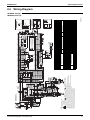
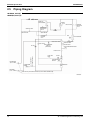
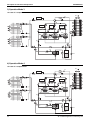
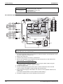
SiENBE28-901
Piping Diagram
LRLEQ5A, 6AY1(E)
LRMEQ5A, 6AY1(E)
FILTER
CHECK VALVE
RECEIVER
DOUBLE PIPE
HEAT EXCHANGER
SERVICE PORT
CHECK VALVE
ELECTRONIC
EXPANSION
VALVE
FUSIBLE
PLUG
CHECK VALVE
PRESSURE
REGULATING
VALVE
FILTER
SIGHT GLASS
ELECTRONIC
EXPANSION
VALVE
FILTER
M
HPS
STOP VALVE
FAN
HEAT EXCHANGER
STOP VALVE
SERVICE PORT
FOUR WAY VALVE
GAUGE PORT
HIGH PRESSURE
SWITCH
(DEFROST)
HIGH PRESSURE SENSOR
SENPH
CAPILLARY
TUBE
FILTER
OIL
SEPARATOR
GAUGE PORT
LIQUID PIPE
φ9.5 C1220T
SERVICE PORT
CHECK VALVE
HIGH PRESSURE
HPS
SWITCH
LOW PRESSURE
SENSOR
SENPL
COMPRESSOR
INV
GAS PIPE
φ19.1 C1220T
STOP VALVE (WITH SERVICE PORT φ7.9mm FLARE CONNECTION)
3D064606A
18
Air Cooled Refrigeration Condensing Unit
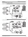
SiENBE28-901
Standard Specification
LRLEQ8A, 10A, 12AY1(E)
LRMEQ8A, 10A, 12AY1(E)
CHECK VALVE
RECEIVER
FILTER
ELECTRONIC
EXPANSION
VALVE
SERVICE PORT
PLATE TYPE HEAT
EXCHANGER
CHECK VALVE
FUSIBLE
PLUG
CHECK VALVE
PRESSURE
REGULATING
VALVE
FILTER
SIGHT GLASS
ELECTRONIC
EXPANSION
VALVE
FAN
S4PH
FOUR WAY VALVE
STOP VALVE
HIGH PRESSURE
SWITCH
(DEFROST)
FILTER
HEAT EXCHANGER
M
STOP VALVE
SERVICE PORT
GAUGE PORT
HIGH PRESSURE SENSOR
S1NPH
CHECK VALVE
CHECK VALVE
LOW PRESSURE
SENSOR
HIGH PRESSURE
S1PH
SWITCH
CHECK
VALVE FILTER
CAPILLARY
TUBE HIGH PRESSURE
SWITCH S2PH
OIL
SEPARATOR
CAPILLARYFILTER
TUBE
OIL
SEPARATOR
GAUGE PORT
LIQUID PIPE
φ9.5 C1220T
SERVICE PORT
FILTER
SV
ELECTRONIC
EXPANSION
VALVE
COMPRESSOR
INV
COMPRESSOR
SOLENOID CHECK STD
VALVE
VALVE
S1NPL
GAS PIPE
φ25.4 C1220T
STOP VALVE (WITH SERVICE PORT φ7.9mm FLARE CONNECTION)
3D064605
Air Cooled Refrigeration Condensing Unit
19
Standard Specification
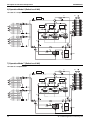
SiENBE28-901
LRLEQ15A, 20AY1(E)
LRMEQ15A, 20AY1(E)
CHECK VALVE
RECEIVER
FILTER
ELECTRONIC
EXPANSION
VALVE
SERVICE PORT
PLATE TYPE HEAT
EXCHANGER
CHECK VALVE
FUSIBLE
PLUG
CHECK VALVE
PRESSURE
REGULATING
VALVE
FILTER
SIGHT GLASS
FAN
ELECTRONIC
EXPANSION
VALVE
S4PH
FOUR WAY VALVE
STOP VALVE
HIGH PRESSURE
SWITCH
(DEFROST)
FILTER
HEAT EXCHANGER
M
STOP VALVE
SERVICE PORT
GAUGE PORT
HIGH PRESSURE SENSOR
S1NPH
CHECK VALVE
CHECK VALVE
CHECK VALVE
CHECK
VALVE FILTER
CHECK
VALVE FILTER
LOW PRESSURE
SENSOR
S1NPL
HIGH PRESSURE
S1PH
SWITCH
CAPILLARY
TUBE HIGH PRESSURE
SWITCH S3PH
SV
ELECTRONIC
EXPANSION
VALVE
SV
COMPRESSOR
COMPRESSOR
SOLENOID CHECK STD1
INV
VALVE
OIL
SEPARATOR
CAPILLARY
TUBE HIGH PRESSURE
SWITCH S2PH
OIL
SEPARATOR
CAPILLARYFILTER
TUBE
OIL
SEPARATOR
GAUGE PORT
LIQUID PIPE
φ12.7 C1220T
SERVICE PORT
FILTER
VALVE
COMPRESSOR
SOLENOID CHECK STD2
VALVE
VALVE
GAS PIPE
φ31.8 C1220T
STOP VALVE (WITH SERVICE PORT φ7.9mm FLARE CONNECTION)
3D064603
20
Air Cooled Refrigeration Condensing Unit
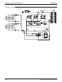
SiENBE28-901
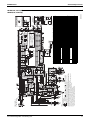
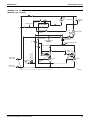
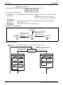
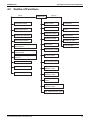
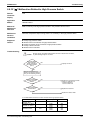
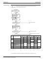
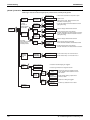
2.6
Standard Specification
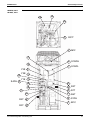
Description and Layout of Functional Parts and Piping
Diagram
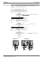
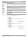
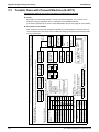
LRMEQ5, 6AY1
LRLEQ5, 6AY1
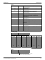
No.
Name
Symbol
1
Inverter compressor (INV)
M1C
2
M1F
Y1E
Not used.
Y2E
5
6
7
Fan motor
Electronic expansion valve
(Main: EV1)
Electronic expansion valve
(Injection: EV2)
Four way valve
High pressure sensor
Low pressure sensor
Function
An inverter-driven compressor, which runs at operating frequencies in the
range of 52Hz to 218Hz.
Used to operate a fan for heat exchange through an air heat exchanger.
8
High pressure switch
S1PH
9
High pressure switch
S4PH
10
Fusible plug
—
11
Pressure regulating valve
—
Used to control the injection flow rate and the compressor overheat
protection.
Not used.
Used to detect high pressure.
Used to detect low pressure.
In order to prevent the increase of high pressure when a malfunction
occurs, this switch activated at high pressure of 3.8MPa or more to stop the
compressor operation.
Not used.
When the refrigerant of the receiver unit reaches a temperature of 70°C to
75°C, the fusible head of plug will melt, thus discharging the refrigerant of
high temperature and high pressure.
Opens when the pressure reaches 4.0 MPa. This prevents an excessive
pressure rise caused by the pipes being completely filled with liquid when
not in operation.
12
—
Used to cool the liquid refrigerant from the liquid receiver.
—
Used to service.
—
Used to service.
15
16
17
Double pipe heat
exchanger
Stop valve (Heat
exchanger on primary side)
Stop valve (Double pipe
heat exchanger on
secondary side)
Service port
Service port
Service port
—
—
—
18
Oil separator
—
19
Liquid receiver
—
20
—
D
Sight glass
Thermistor (Outdoor air:
Ta)
Thermistor (Suction pipe:
Ti)
Thermistor (INV discharge
pipe: Td1)
Thermistor (Heat
exchanger deicer: Tce)
For gas (high pressure).
For liquid (high pressure).
For gas (low pressure).
Refrigerant gas discharged from the compressor contains lubricating oil in
the compressor. If the amount of this lubricating oil is large, the oil quantity
in the compressor will become short, which may result in defective
lubrication.
Furthermore, this oil stains the heat transfer surface of condenser or
evaporator and reduces the effectiveness of the heat exchanger. To avoid
that, an oil separator is installed in close proximity to the discharge pipe of
the compressor, where oil is separated and collected to return to the
compressor.
Used to compensate the variations in handling of refrigerant, thus providing
stable operating conditions at all times. In order to repair in the refrigerant
circuit, this receiver collects the refrigerant and facilitates the repairing of
the parts.
Used to test run and service.
E
Thermistor (Double pipe
heat exchanger outlet: Tg)
R5T
F
Thermistor (Double pipe
heat exchanger inlet: TL)
R6T
3
4
13
14
A
B
C
Y3S
S1NPH
S1NPL
Air Cooled Refrigeration Condensing Unit
R1T
Used to detect the outdoor temperature and control the fan operation.
R2T
R31T
Used to detect the suction pipe temperature of M1C compressor and
protect this compressor.
Used to detect the discharge pipe temperature of M1C compressor and
control over discharge pipe temperature of this compressor for protection.
R3T
Not used.
Used to detect the gas temperature at evaporator side of double pipe heat
exchanger, and keep the constant overheated degree of double pipe heat
exchanger.
Used to detect the gas saturation temperature at evaporator side of double
pipe heat exchanger.
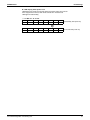
21
Standard Specification
SiENBE28-901
LRMEQ5, 6AY1
LRLEQ5, 6AY1
FILTER
CHECK VALVE
(F)
(16)
(E)
SERVICE PORT
(19)
RECEIVER
(12)
DOUBLE PIPE
HEAT EXCHANGER
FUSIBLE(10)
PLUG
CHECK VALVE
PRESSURE
REGULATING
VALVE
(11)
ELECTRONIC
EXPANSION (4)
VALVE
FILTER
(D)
SIGHT GLASS (20)
CHECK VALVE
FAN
ELECTRONIC
EXPANSION (3)
VALVE
(2)
HEAT EXCHANGER
M
S4PH
(A)
FILTER
STOP VALVE
FOUR WAY VALVE
(13)
(5)
STOP VALVE
(14)
HIGH PRESSURE
SWITCH
(DEFROST)
GAUGE PORT
HIGH PRESSURE SENSOR
(9)
S1NPH
(6)
CHECK VALVE
SERVICE PORT
(17)
GAUGE PORT
SERVICE PORT
CAPILLARY
TUBE
LIQUID PIPE
φ9.5 C1220T
FILTER
OIL
SEPARATOR
(15)
(18)
HIGH PRESSURE
(8) SWITCH
S1PH
(C)
LOW PRESSURE
SENSOR
COMPRESSOR
INV
S1NPL
(1)
(7)
GAS PIPE
φ19.1 C1220T
(B)
STOP VALVE (WITH SERVICE PORT φ7.9mm FLARE CONNECTION)
22
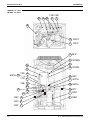
Air Cooled Refrigeration Condensing Unit
SiENBE28-901
Standard Specification
LRMEQ5, 6AY1
LRLEQ5, 6AY1
19
10
18
C
R31T
2 M1F
17
6 S1NPH
12
7 S1NPL
Y3S 5
13
Y2E 4
Y1E 3
S4PH 9
14
15
16
B R2T
11
A R1T
20
R5T E
F R6T
8 S1PH
1 M1C
R3T D
Air Cooled Refrigeration Condensing Unit
23
Standard Specification
SiENBE28-901
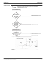
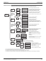
LRMEQ8, 10, 12AY1
LRLEQ8, 10, 12AY1
No.
Name
Symbol
1
Inverter compressor (INV)
M1C
2
3
M2C
M1F
Y1E
Not used.
5
Standard compressor (STD)
Fan motor
Electronic expansion valve
(Main: EV1)
Electronic expansion valve
(Injection: EV2)
Function
An inverter-driven compressor, which runs at operating frequencies in the
range of 52Hz to 232Hz.
A compressor, which runs with commercial power supply.
Used to operate a fan for heat exchange through an air heat exchanger.
Y2E
6
Electronic expansion valve
(M1C: EV3)
Y3E
7
8
9
10
13
Solenoid valve
Four way valve
High pressure sensor
Low pressure sensor
High pressure switch (for
INV)
High pressure switch (for
STD)
High pressure switch
Used to control the injection flow rate and the compressor overheat
protection.
Returns the oil to the inverter compressor and creates a gas-injection
economizer circuit.
In addition, this controls the difference in discharge pipe temperatures
between INV compressor and STD compressor.
Returns the oil to the M2C and creates a gas-injection economizer circuit.
Not used.
Used to detect high pressure.
Used to detect low pressure.
14
Fusible plug
—
15
Pressure regulating valve
—
16
—
—
Used to service.
—
Used to service.
19
20
21
Plate type heat exchanger
Stop valve (Heat
exchanger on primary side)
Stop valve (Double pipe heat
exchanger on secondary side)
Service port
Service port
Service port
Not used.
When the refrigerant of the receiver unit reaches a temperature of 70°C to
75°C, the fusible head of plug will melt, thus discharging the refrigerant of
high temperature and high pressure.
Opens when the pressure reaches 4.0 MPa. This prevents an excessive
pressure rise caused by the pipes being completely filled with liquid when
not in operation.
Used to cool the liquid refrigerant from the liquid receiver.
—
—
—
22
Oil separator
—
23
Liquid receiver
—
24
Sight glass
Thermistor (Outdoor air:
Ta)
Thermistor (Suction pipe:
Ti)
Thermistor (INV discharge
pipe: Td1)
Thermistor (STD discharge
pipe: Td2)
Thermistor (Heat
exchanger deicer: Tce)
Thermistor (Plate type heat
exchanger outlet: Tg)
Thermistor (Plate type heat
exchanger inlet: TL)
—
For gas (high pressure).
For liquid (high pressure).
For gas (low pressure).
Refrigerant gas discharged from the compressor contains lubricating oil in the
compressor. If the amount of this lubricating oil is large, the oil quantity in the
compressor will become short, which may result in defective lubrication.
Furthermore, this oil stains the heat transfer surface of condenser or evaporator
and reduces the effectiveness of the heat exchanger. To avoid that, an oil
separator is installed in close proximity to the discharge pipe of the compressor,
where oil is separated and collected to return to the compressor.
Used to compensate the variations in handling of refrigerant, thus providing
stable operating conditions at all times. In order to repair in the refrigerant
circuit, this receiver collects the refrigerant and facilitates the repairing of the
parts.
Used to test run and service.
4
11
12
17
18
A
B
C
D
E
F
G
24
Y2S
Y3S
S1NPH
S1NPL
S1PH
S2PH
S4PH
In order to prevent the increase of high pressure when a malfunction
occurs, this switch activated at high pressure of 3.8MPa or more to stop the
compressor operation.
R1T
Used to detect the outdoor temperature and control the fan operation.
R2T
R32T
Used to detect the suction pipe temperature of M1C and M2C compressor
and protect this compressor.
Used to detect the discharge pipe temperature of M1C compressor and
control over discharge pipe temperature of this compressor for protection.
Used to detect the discharge pipe temperature of M2C compressor and
control over discharge pipe temperature of this compressor for protection.
R3T
Not used.
R31T
R5T
R6T
Used to detect the gas temperature at evaporator side of double pipe heat exchanger,
and keep the constant overheated degree of double pipe heat exchanger.
Used to detect the gas saturation temperature at evaporator side of double
pipe heat exchanger.
Air Cooled Refrigeration Condensing Unit
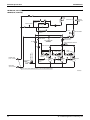
SiENBE28-901
Standard Specification
LRMEQ8, 10, 12AY1
LRLEQ8, 10, 12AY1
CHECK VALVE
(14)
(G)
(23)
ELECTRONIC
EXPANSION (5)
VALVE
(20)
SERVICE PORT
(F)
PLATE TYPE HEAT(16)
EXCHANGER
RECEIVER
FILTER
FUSIBLE
PLUG
(15)
CHECK VALVE
PRESSURE
REGULATING
VALVE
(E)
FILTER
SIGHT GLASS (24)
CHECK VALVE
(3)
FAN
ELECTRONIC
EXPANSION (4)
VALVE
HEAT EXCHANGER
M
(A)
S4PH
(17)
FILTER
STOP VALVE
FOUR WAY VALVE
STOP VALVE
(18)
HIGH PRESSURE
SWITCH
(DEFROST)
(13)
(8)
SERVICE PORT (19)
GAUGE PORT
HIGH PRESSURE SENSOR
(9)
S1NPH
CHECK VALVE
CHECK VALVE
LOW PRESSURE
SENSOR
CAPILLARYFILTER
TUBE
HIGH PRESSURE
(11) SWITCH
(22)
CAPILLARY
TUBE HIGH PRESSURE
(12) SWITCH S2PH
S1PH
(C)
ELECTRONIC
EXPANSION
(6)
VALVE
CHECK
VALVE FILTER
COMPRESSOR
INV
(1)
S1NPL
OIL
SEPARATOR
GAUGE PORT
LIQUID PIPE
φ9.5 C1220T
SERVICE PORT
(21)
OIL
SEPARATOR
FILTER
(22)
(D)
SV
COMPRESSOR
SOLENOID CHECK STD
VALVE
(7)
VALVE
(2)
(10)
(B)
GAS PIPE
φ25.4 C1220T
STOP VALVE (WITH SERVICE PORT φ7.9mm FLARE CONNECTION)
Air Cooled Refrigeration Condensing Unit
25
Standard Specification
SiENBE28-901
LRMEQ8, 10, 12AY1
LRLEQ8, 10, 12AY1
Y3E Y2S
23 14 22 6 7
16
D R32T
C
R31T
3 M1F
9 S1NPH
19
17
S4PH 13
21
10 S1NPL
Y3S 8
B R2T
Y1E 4
Y2E 5
11 S1PH
12 S2PH
20
15
18
24
R6T G
A R1T
1 M1C
2 M2C
R3T E
R5T F
26
Air Cooled Refrigeration Condensing Unit
SiENBE28-901
Standard Specification
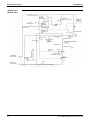
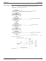
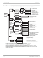
LRMEQ15, 20AY1
LRLEQ15, 20AY1
No.
Name
Symbol
1
Inverter compressor (INV)
M1C
2
3
4
5
M2C
M3C
M1F
M2F
7
Standard compressor (STD 1)
Standard compressor (STD 2)
Fan motor
Fan motor
Electronic expansion valve
(Main: EV1)
Electronic expansion valve
(Injection: EV2)
8
Electronic expansion valve
(M1C: EV3)
Y3E
9
10
11
12
13
14
15
16
17
Solenoid valve
Four way valve
Solenoid valve
High pressure sensor
Low pressure sensor
High pressure switch (for INV)
High pressure switch (for STD 1)
High pressure switch (for STD 2)
High pressure switch
Y2S
Y3S
Y5S
S1NPH
S1NPL
S1PH
S2PH
S3PH
S4PH
18
Fusible plug
—
19
Pressure regulating valve
—
20
—
—
Used to service.
—
Used to service.
23
24
25
Plate type heat exchanger
Stop valve (Heat
exchanger on primary side)
Stop valve (Double pipe heat
exchanger on secondary side)
Service port
Service port
Service port
Not used.
When the refrigerant of the receiver unit reaches a temperature of 70°C to
75°C, the fusible head of plug will melt, thus discharging the refrigerant of
high temperature and high pressure.
Opens when the pressure reaches 4.0 MPa. This prevents an excessive
pressure rise caused by the pipes being completely filled with liquid when
not in operation.
Used to cool the liquid refrigerant from the liquid receiver.
—
—
—
26
Oil separator
—
27
Liquid receiver
—
28
A
Sight glass
Thermistor (Outdoor air: Ta)
—
R1T
B
Thermistor (Suction pipe: Ti)
R2T
C
Thermistor (INV discharge
pipe: Td1)
Thermistor (STD 1
discharge pipe: Td2)
Thermistor (STD 2
discharge pipe: Td3)
Thermistor (Heat
exchanger deicer: Tce)
Thermistor (Plate type heat
exchanger outlet: Tg)
Thermistor (Plate type heat
exchanger inlet: TL)
R31T
R33T
For gas (high pressure).
For liquid (high pressure).
For gas (low pressure).
Refrigerant gas discharged from the compressor contains lubricating oil in the
compressor. If the amount of this lubricating oil is large, the oil quantity in the
compressor will become short, which may result in defective lubrication.
Furthermore, this oil stains the heat transfer surface of condenser or evaporator
and reduces the effectiveness of the heat exchanger. To avoid that, an oil
separator is installed in close proximity to the discharge pipe of the compressor,
where oil is separated and collected to return to the compressor.
Used to compensate the variations in handling of refrigerant, thus providing stable
operating conditions at all times. In order to repair in the refrigerant circuit, this
receiver collects the refrigerant and facilitates the repairing of the parts.
Used to test run and service.
Used to detect the outdoor temperature and control the fan operation.
Used to detect the suction pipe temperature of M1C~M3C compressor and
protect this compressor.
Used to detect the discharge pipe temperature of M1C compressor and
control over discharge pipe temperature of this compressor for protection.
Used to detect the discharge pipe temperature of M2C compressor and
control over discharge pipe temperature of this compressor for protection.
Used to detect the discharge pipe temperature of M3C compressor and
control over discharge pipe temperature of this compressor for protection.
R3T
Not used.
6
21
22
D
E
F
G
H
Air Cooled Refrigeration Condensing Unit
Function
An inverter-driven compressor, which runs at operating frequencies in the
range of 52Hz to 232Hz.
A compressor, which runs with commercial power supply.
Used to operate a fan on the right for heat exchange through an air heat exchanger.
Used to operate a fan on the left for heat exchange through an air heat exchanger.
Y1E
Not used.
Y2E
Used to control the injection flow rate and the compressor overheat
protection.
Returns the oil to the inverter compressor and creates a gas-injection
economizer circuit.
In addition, this controls the difference in discharge pipe temperatures
between INV compressor and STD compressor.
Returns the oil to the M2C and creates a gas-injection economizer circuit.
Not used.
Returns the oil to the M3C and creates a gas-injection economizer circuit.
Used to detect high pressure.
Used to detect low pressure.
R32T
R5T
R6T
In order to prevent the increase of high pressure when a malfunction
occurs, this switch activated at high pressure of 3.8MPa or more to stop the
compressor operation.
Used to detect the gas temperature at evaporator side of double pipe heat exchanger,
and keep the constant overheated degree of double pipe heat exchanger.
Used to detect the gas saturation temperature at evaporator side of double
pipe heat exchanger.
27
Standard Specification
SiENBE28-901
LRMEQ15, 20AY1
LRLEQ15, 20AY1
CHECK VALVE
(H)
(27)
ELECTRONIC
EXPANSION (7)
VALVE
(24)
SERVICE PORT
(G)
RECEIVER
FILTER
FUSIBLE
PLUG
(18)
CHECK VALVE
PRESSURE
REGULATING
VALVE
(19)
PLATE TYPE HEAT
(20)
EXCHANGER
FILTER
(F)
SIGHT GLASS (28)
CHECK VALVE
FAN
ELECTRONIC
EXPANSION (6)
VALVE
(4)
(5)
HEAT EXCHANGER
M
(21)
S4PH
(10)
GAUGE PORT
HIGH PRESSURE SENSOR
(17)
CHECK VALVE
CHECK
VALVE FILTER
CAPILLARY
TUBE HIGH PRESSURE
(15) SWITCH S2PH
(C)
ELECTRONIC
EXPANSION (8)
VALVE
SV
(26)
OIL
SEPARATOR
PRESSURE
(14) HIGH
SWITCH S1PH
(26)
OIL
SEPARATOR
GAUGE PORT
LOW PRESSURE
SENSOR
SERVICE PORT
LIQUID PIPE
φ12.7 C1220T
CAPILLARY
FILTER
TUBE
CHECK VALVE
CHECK VALVE
FILTER
(25)
(12)
S1NPH
CHECK
VALVE FILTER
CAPILLARY
TUBE
HIGH PRESSURE
(16) SWITCH S3PH
(D)
COMPRESSOR
COMPRESSOR
INV (1) SOLENOID CHECK STD1
S1NPL
VALVE
(9)
VALVE
(2)
SV
(26)
OIL
SEPARATOR
FILTER
(A)
STOP VALVE
SERVICE PORT (23)
FOUR WAY VALVE
STOP VALVE
(22)
HIGH PRESSURE
SWITCH
(DEFROST)
(E)
COMPRESSOR
SOLENOID CHECK STD2
VALVE
VALVE
(3)
(11)
(13)
GAS PIPE
φ31.8 C1220T
(B)
STOP VALVE (WITH SERVICE PORT φ7.9mm FLARE CONNECTION)
28
Air Cooled Refrigeration Condensing Unit
SiENBE28-901
Standard Specification
LRMEQ15, 20AY1
LRLEQ15, 20AY1
20
27
18
26
Y3E Y2S Y5S
9 11
8
E R33T
S1PH 14
D R32T
C R31T
5
23
25
Y3S 10
21
S4PH 17
Y2E 7
19
24
Y1E 6
28
22
R3T F
R6T H
4
13 S1NPL
12 S1NPH
B R2T
16 S3PH
15 S2PH
A R1T
1 M1C
2 M2C
3
M3C
R5T G
Air Cooled Refrigeration Condensing Unit
29
Field Settings
SiENBE28-901
3. Field Settings
3.1
Field Setting From Outdoor Unit
The target evaporation temperature can be calculated as follows:
Tst : Target evaporation temperature
Tsd : Evaporation temperature set by dip switches
ΔTsp : Temperature correction setting by pushbuttons.
ΔTsn : Temperature correction setting during night-time operation
Tst = Tsd + ΔTsp + ΔTsn
The evaporation temperature can be set by dip switches and pushbuttons on the outdoor unit
PCB.
The dip switches can be set when the power is turned off, while the pushbuttons can be set
while the condensing unit is operating.
Note that the actual evaporation temperature may be lower than that specified, if the outdoor
temperature is too low. (This is intended to protect the compressors.)
Do not set the evaporation temperature to less than the values below. (This may damage the
compressors.)
MT series : -20°C
LT series : -45°C
(1) Field settings by dip switches
Be sure to turn off the power before changing the DIP switch settings.
DS1-1 to 3 enable setting the saturated temperature equivalent to suction pressure (in
increments of 5°C).
Do not change the settings of DS1-4, DS2-1 to 4.
Switch box
Location of soft switches
Location of dip switches
DS1
DS2
1 2 3 4
5 6 7 8
ON
Main PCB
OFF
Dip switches 1 to 3
The evaporation temperature setting
(specified using the dip switches) can
be changed using the pushbuttons,
within the range of -4K to +4K, in steps
of about 1K. Refer the setting method
on next page.
30
Air Cooled Refrigeration Condensing Unit
SiENBE28-901
Field Settings
Tsd
LRMEQ** LRLEQ**
DS1
ON
-10°C
(0.47MPa)
OFF
-35°C
(0.11MPa)
1 2 3 4
Factory set
ON
OFF
1 2
3
OFF
3
OFF
3
0°C
(0.69MPa)
-25°C
(0.22MPa)
5°C
(0.82MPa)
-20°C
(0.29MPa)
4
ON
4
ON
10°C
(0.98MPa)
OFF
1 2
-5°C
(0.56MPa)
OFF
3
-40°C
(0.07MPa)
4
ON
1 2
-45°C
(0.03MPa)
1 2
-15°C
(0.37MPa)
3
OFF
4
ON
1 2
ON
1 2
-20°C
(0.29MPa)
Tsd
LRMEQ** LRLEQ**
DS1
3
4
-30°C
(0.16MPa)
4
Tsd: The evaporation temperature set by the dip switches.
Air Cooled Refrigeration Condensing Unit
31
Field Settings
SiENBE28-901
Setting at replacement by spare PCB
Caution
DIP switch setting after changing the main PCB to spare parts PCB
In case of repair using this part, replace the part according to the following instruction. Make the
following capacity and refrigeration / freezing settings subject to application models.
Cut the power supply of the outdoor unit once and switch it on again after setting the switch of
subject.
Freezer: LRLEQ5~20AY1 (E)
LED
EB****
Factory Set (the position of a switch)
DS1DS2
ON
OFF
1
Applicable model
LRLEQ5AY1 (E)
2 3
DS1
4
1
2 3
DS2
4
Setting method (the position of switches)
Set DS2-2 and DS2-4 to
ON
ON
OFF
1 2 3 4
LRLEQ6AY1 (E)
1 2 3 4
Set DS2-1 and DS2-4 to
ON
ON
OFF
1 2 3 4
LRLEQ8AY1 (E)
1 2 3 4
Set DS2-1, DS2-2 and
DS2-4 to ON
ON
OFF
1 2 3 4
1 2 3 4
LRLEQ10AY1 (E)
Set DS1-4 and DS2-4 to
ON
ON
OFF
1 2 3 4
LRLEQ12AY1 (E)
1 2 3 4
Set DS1-4, DS2-2 and
DS2-4 to ON
ON
OFF
1 2 3 4
LRLEQ15AY1 (E)
1 2 3 4
Set DS1-4, DS2-1 and
DS2-4 to ON
ON
OFF
1 2 3 4
LRLEQ20AY1 (E)
1 2 3 4
Set DS1-4, DS2-1, DS2-2
and DS2-4 to ON
ON
OFF
1 2 3 4
32
1 2 3 4
Air Cooled Refrigeration Condensing Unit
SiENBE28-901
Field Settings
Refrigerator: LRMEQ5~20AY1 (E)
LED
EB****
Factory Set (the position of a switch)
DS1DS2
ON
OFF
1
Applicable model
LRMEQ5AY1 (E)
2 3
DS1
4
1
2 3
DS2
4
Setting method (the position of switches)
Set DS2-2 to ON
ON
OFF
1 2 3 4
LRMEQ6AY1 (E)
1 2 3 4
Set DS2-1 to ON
ON
OFF
1 2 3 4
LRMEQ8AY1 (E)
1 2 3 4
Set DS2-1 and DS2-2 to
ON
ON
OFF
1 2 3 4
LRMEQ10AY1 (E)
1 2 3 4
Set DS1-4 to ON
ON
OFF
1 2 3 4
LRMEQ12AY1 (E)
1 2 3 4
Set DS1-4 and DS2-2 to
ON
ON
OFF
1 2 3 4
LRMEQ15AY1 (E)
1 2 3 4
Set DS1-4 and DS2-1 to
ON
ON
OFF
1 2 3 4
LRMEQ20AY1 (E)
1 2 3 4
Set DS1-4, DS2-1 and
DS2-2 to ON
ON
OFF
1 2 3 4
Air Cooled Refrigeration Condensing Unit
1 2 3 4
33
Field Settings
SiENBE28-901
(2) Setting in service mode
Using pushbuttons on the Main PCB (A1P) enables a variety of settings shown below.
BS1
BS2
BS3
MODE
SET
RETURN
BS4
BS5
RESET
The following 4 modes are available.
a. Setting mode 1 ...... Initial state (while in normal operation): Used to make setting of the method of "Cool/Heat
(H1P: OFF)
selection".
This mode is displayed while in "malfunction",
"low noise control", and "demand control" as well.
b. Setting mode 2
Setting mode 3 ...... Used to make changes of operating conditions or settings of a variety of addresses,
(H1P: ON)
mainly for service work.
c. Monitor mode ...... Used to check the contents set in Setting mode 2.
(H1P: BLINK)
Procedure for changing mode
While in each mode, use the MODE button to change settings as shown below.
Setting mode 3
Simultaneously press and hold the
BS1 (MODE) and BS3 (RETURN)
Press and hold the BS1
for a period of 5 seconds.
(MODE) for a period of
Press the BS1 (MODE)
(Normal)
five seconds.
once.
Setting mode 2
Setting mode 1
Monitor mode
Press the BS1
MODE
MODE
MODE
(MODE) once.
ON
OFF
BLINK
H1P
H1P
H1P
Steps to change mode
Caution
Turn off the RUN switch of the outdoor unit in case of the setting.
Press and hold the BS1
(MODE) for a period of
five seconds.
Setting mode 2
Selection of
SET
setting items
Press the BS3
(RETURN).
Selection of
SET
setting contents
Press the BS3
(RETURN).
Display of
setting contents
Press the BS3
(RETURN).
OP : Select mode with the use of BS2
(SET) in each selection step.
Setting mode 1
(Initial state)
Press the BS1 (MODE) once.
Monitor mode
Selection of
SET
check items
Press the BS3
(RETURN).
Display of contents
Press the BS3
(RETURN).
Press the BS1
(MODE).
Press the BS1
(MODE).
34
Air Cooled Refrigeration Condensing Unit
SiENBE28-901
Field Settings
LED display when power is on
H2P blinks for the first five seconds when the power supply is turned on.
If the equipment is normal, H2P will be turned off in five seconds.
H2P lights for abnormality.
k: ON h: OFF l: BLINK
No.
H1P
H2P
H3P
H4P
H5P
H6P
H7P
1
h
l
k
h
h
h
h
No.
H1P
H2P
H3P
H4P
H5P
H6P
H7P
1
h
h
k
h
h
h
h
Air Cooled Refrigeration Condensing Unit
(Immediately after power on)
(5 seconds after power on)
35
Field Settings
SiENBE28-901
b-1. Setting mode 2
No.
0
2
Setting item
Display of setting items
H1P H2P H3P H4P H5P H6P H7P
ΔTsp: Fine-tuning setting of
evaporation temperature
k
Current limitation setting
3
Setting of limit value of outdoor fan
taps
5
Setting of external low noise
operation
(Tax1, 2 and Tay1, 2 are set by
setting 2-21. )
6
k
k
h
h
h
h
h
h
h
h
h
h
h
h
k
k
h
h
k
0K (Factory set)
-1°C
-2°C
-3°C
-4°C
ΔTsp
-5°C
+1°C
+2°C
+3°C
+4°C
+5°C
LRM(L)EQ
5,6AY1 8,10,12AY1 15,20AY1
No limitation. (Factory set)
10A
20A
36A
9A
18A
30A
7A
14A
27A
(Factory set)
Setting 1
Setting 2
Setting 3
Setting 4
Setting 5
Setting of night-time low noise
operation (Only connected to
AIRNET)
8
Night-time low noise start setting.
It uses it for setting 2-7 and 2-11.
(Only connected to AIRNET)
9
Night-time low noise end setting.
It uses it for setting 2-7 and 2-11.
(Only connected to AIRNET)
H2P H3P H4P
h
h
h
h
h
h
h
h
h
h
h
h
h
h
h
h
h
h
h
h
h
h
h
h
h
h
k
h
h
k
h
h
k
H5P
h
h
h
h
k
k
k
k
h
h
h
H6P H7P
h
h
h
k
k
h
k
k
h
h
h
k
k
h
k
k
h
h
h
k
k
h
H1P H2P H3P H4P H5P H6P H7P
k
k
k
k
H2P H3P H4P
h
h
h
h
h
h
h
h
h
h
h
k
h
k
h
k
h
h
k
h
h
h
h
h
h
k
k
h
k
k
h
6 (Tamb≤Tax1)
7(Tay1<Tamb≤Tax2)
9(Tamb<Tay2) (Factory set)
5(Tamb≤Tax1)
6(Tay1<Tamb≤Tax2)
9(Tamb<Tay2)
(Factory set) 0
1
63
7
H1P
k
k
k
k
k
k
H1P
k
k
k
k
k
k
k
k
k
k
k
h
h
h
h
h
h
h
h
h
h
h
k
h
h
k
h
h
k
h
h
k
h
h
h
H5P
h
h
k
h
h
h
H6P H7P
h
k
k
h
h
h
h
h Details
depend on
h
h the
h
h following.(*1)
H1P H2P H3P H4P H5P H6P H7P
k
AIRNET address
h
Display of setting conditions
k
k
k
h
h
h
h
h
h
h
k
k
k
h
h
k
h
h
k
k
h
h
h
h
h
k
k
h
h
h
h
k
h
H1P H2P H3P H4P
k
h
h
h
k
h
h
h
~
k
h
k
k
Standard
setting
9
8
7
6
5
4
H5P H6P H7P Please give the
h
h
h address of 1 or
h
k
k more when you do
the AIRNET.
Binary system for
k
k
k address(six digits)
High static
pressure setting H1P H2P
9
k
h
7
k
h
8
k
h
6
k
h
5
k
h
4
k
k
H3P H4P H5P H6P H7P
h
h
h
h
k
h
h
h
h
k
h
h
h
h
k
h
h
h
h
k
h
h
h
h
k
h
h
h
h
h
h
21:00 (Factory set)
22:00
23:00
20:00
H1P
k
k
k
k
H2P
h
h
h
h
H3P
h
h
h
h
H4P H5P H6P
h
h
h
h
h
k
h
k
h
k
h
h
H7P
k
h
h
h
k
7:00 (Factory set)
8:00
9:00
6:00
H1P
k
k
k
k
H2P
h
h
h
h
H3P
h
h
h
h
H4P H5P H6P
h
h
h
h
h
k
h
k
h
k
h
h
H7P
k
h
h
h
ΔTsn: Evaporation temperature
11
correction setting during
operation at night-time
k
h
h
k
h
k
k
H1P H2P H3P H4P H5P H6P H7P
+1°C(Factory set)
k
h
h
h
h
h
k
+2°C
k
h
h
h
h
k
h
+3°C
k
h
h
h
k
h
h
0°C
k
h
h
k
h
h
h
As for Factory set, time zone between 2-8 and 2-9 becomes effective for setting.
Setting of external temperature of
21 outdoor fan tap
It uses it by setting 2-5.
k
h
h
k
k
h
k
Tax1
26°C
20°C
27°C
Tay1
28°C
22°C
29°C
Tax2
31°C
26°C
32°C
Tay2 H1P H2P
33°C k
h
28°C k
h
34°C k
h
H3P H4P H5P H6P
h
h
h
h
h
h
h
k
h
h
k
h
H7P
k
h
h
H1P H2P H3P H4P H5P H6P H7P
of high static pressure of
40 Setting
outdoor fan
k
h
k
h
h
h
k
Standard setting
(Factory set)
High static
pressure setting
k
h
h
h
h
h
k
k
h
h
h
h
k
h
The number in the “No.” column represent the number of times to press the SET (BS2) button.
(*1)
Model name
Factory set
Setting 1
Setting 2
Setting 3
Setting 4
Setting 5
36
Standard setting
LRM(L)EQ6,12,20AY1
LRM(L)EQ5,8,10,15,20AY1
9
9
8
10
7
8
6
7
5
6
5
5
High static pressure setting
LRM(L)EQ6,12,15,20AY1
LRM(L)EQ5,8,10AY1
8
8
7
9
6
7
5
6
5
5
5
5
Air Cooled Refrigeration Condensing Unit
SiENBE28-901
Field Settings
b-2. Setting mode 2 (for service)
4
Setting item
Display of setting items
H1P H2P H3P H4P H5P H6P H7P
INV compressor max. frequency
step control
Setting of night-time compressor
reduction
10 frequency
Set the start time with 2-8, set the
end time with 2-9.
k
k
h
h
h
h
h
k
k
h
h
k
Display of setting conditions
5A 6A
15 21
14 18
13 17
21
16
15
14
8A
34
38
42
10A
39
36
42
40
36
35
34
12A 15A 20A H1P H2P
42 58 62 k h
38 62 58 k h
36
57
k h
60
k h
56
k h
55
k h
54
k h
h
Compressor step control
No.
h
5A 6A 8A 10A 12A 15A
20A
Compressor steps (Factory set)
Setting step: 1
Setting step: 2
Setting step: 2
Setting step: 4
Setting step: 3
Setting step: 6
Setting step: 4
Setting step: 8
Setting step: 5 Setting step: 10
Setting step: 6 Setting step: 12
of fan revolution
14 Correction
according to the high pressure
k
h
h
k
k
k
h
recovery continuous operation
19 Oil
time
k
h
k
h
h
k
k
change for cooling capacity
20 Speed
reduction
k
h
k
h
k
h
h
H1P
k
k
k
k
k
k
k
H3P
h
h
h
h
h
h
h
H4P
h
h
h
h
h
h
h
H5P H6P H7P
h h h
h h k
h k h
h k k
k h h
k h k
k k h
(Factory set)
H2P
h
h
h
h
h
h
h
H3P
h
h
h
h
h
h
h
H4P
h
h
h
h
h
h
h
H5P
h
h
h
h
k
k
k
H6P
h
h
k
k
h
h
k
H7P
h
k
h
k
h
k
h
High pressure correction = 0 (Factory set)
High pressure correction = -0.2
High pressure correction = 0.2
High pressure correction = 0.4
High pressure correction = 0.6
H1P
k
k
k
k
k
H2P
h
h
h
h
h
H3P
h
h
h
h
k
H4P
h
h
h
k
h
H5P H6P H7P
h
h
k
h
k
h
k
h
h
h
h
h
h
h
h
40 min. (Factory set)
30 min.
20 min.
H1P
k
k
k
H2P
h
h
h
H3P
h
h
h
H4P
h
h
h
H5P H6P H7P
h
h
k
h
k
h
k
h
h
30 sec. (Factory set)
10 sec.
H1P H2P H3P H4P H5P H6P H7P
k
h
h
h
h
h
k
k
h
h
h
h
k
h
27 INV compressor forced stop
k
h
k
k
h
k
k
H1P H2P H3P H4P H5P H6P H7P
Normal control (Factory set) k
h
h
h
h
h
k
Inverter compressor forced stop k
h
h
h
h
k
h
To reset the compressor after a forced stop, turn the power off
and back on again.
43 STD1 compressor forced stop
k
k
h
k
h
k
k
H1P H2P H3P H4P H5P H6P H7P
Normal control (Factory set) k
h
h
h
h
h
k
STD1 compressor forced stop k
h
h
h
h
k
h
To reset the compressor after a forced stop, turn the power off
and back on again.
44 STD2 compressor forced stop
k
k
h
k
k
h
h
H1P H2P H3P H4P H5P H6P H7P
Normal control (Factory set) k
h
h
h
h
h
k
STD2 compressor forced stop k
h
h
h
h
k
h
To reset the compressor after a forced stop, turn the power off
and back on again.
c. Setting mode 3 (for servicing)
No.
Setting item
Display of setting items
H1P H2P H3P H4P H5P H6P H7P
the compressor steps
3-21 Changing
during target oil recovery
k
k
h
k
k
h
h
Display of setting conditions
Compressor
frequency
5A, 6A 8A, 10A, 12A 15A, 20A H1P H2P H3P H4P H5P H6P H7P
13
27
34
k h h h h h k
Factory set
17
31
42
k h h h h k h
c. Setting mode 3 (for servicing)
Check when malfunction code “PJ” is displayed.
No.
Setting item
Display of setting items
H1P H2P H3P H4P H5P H6P H7P
3-10 Capacity setting
k
h
h
k
h
k
h
3-26 Setting the freezing and refrigeration
k
h
k
k
h
k
h
3-39 Power supply voltage setting
k
k
h
h
k
k
k
Air Cooled Refrigeration Condensing Unit
Display of setting conditions
LRM(L)EQ5AY1
LRM(L)EQ6AY1
LRM(L)EQ8AY1
LRM(L)EQ10AY1
LRM(L)EQ12AY1
LRM(L)EQ15AY1
LRM(L)EQ20AY1
H1P
k
k
k
k
k
k
k
H2P
h
h
h
h
h
h
h
H3P
h
h
h
h
h
h
h
H4P
h
h
h
h
h
h
k
H5P H6P H7P
h
h
k
h
k
h
h
k
k
k
h
h
k
h
k
k
k
k
h
h
h
Effective setting of Dip switches
Freezing
Refrigeration
H1P
k
k
k
H2P
h
h
h
H3P
h
h
h
H4P
h
h
h
H5P H6P H7P
h
h
k
h
k
h
k
h
h
200V
400V
H1P H2P H3P H4P H5P H6P H7P
k
h
h
h
h
h
k
k
h
h
h
h
k
h
37
Field Settings
SiENBE28-901
d. Setting method with the AIRNET or type-III checker.
1) In case of the AIRNET
• Use Setting Mode 2-6 (AIRNET address).
• Use Setting Mode 2-16 (virtual indoor unit address).
2) In case of a Type-III checker
• Use Setting Mode 2-16 (virtual indoor unit address).
No.
6
Setting item
Display of setting items
H1P H2P H3P H4P H5P H6P H7P
AIRNET address
k
h
h
h
k
k
h
Display of setting conditions
(Factory set) 0
1
63
(Factory set) 0
1
16 Virtual indoor unit address setting
38
k
h
k
h
h
h
63
H1P H2P H3P H4P H5P H6P H7P Please give the
k
h
h
h
h
h
h address of 1 or
more to when you
k
h
h
h
h
h
k do the AIRNET.
~
Uses binary
numbers for the
k
k
k
k
k
k
k address (six digits).
H1P H2P H3P H4P
k
h
h
h
k
h
h
h
~
k
k
k
k
H5P H6P H7P
h
h
h
h
h
k
k
k
k
h • When there is 1 outdoor unit, set the
address to "1".
• When there are multiple outdoor units
(outdoor-outdoor transmission
connection), contact the After Sales
Service Division.
Air Cooled Refrigeration Condensing Unit
SiENBE28-901
Field Settings
3.1.1 Evaporation temperature correction at night-time, using an external
contact
The two methods can be used to increase the evaporation temperature at night-time below:
1. Receiving the time setting from the AIRNET (Setting Mode 2-8·9).
2. Using an external contact.
The following describes the wiring needed to use an external contact.
By a short-circuit between terminals A and C on the PCB (A5P) in the control box, the
evaporation temperature can be corrected at night-time.
For details about the wiring, refer to Figure 1. Protect the terminals using insulation sleeves
or equivalent.
A5P
Electric wire thickness
Wiring length
A B C
Contact rating
1
0.75 - 1.25 mm2
Max. 100 m
Minimum applied load
12 VDC, 1 mA or less
2
X3M
Contact for an evaporation temperature correction at night-time:
Contact ON: Enabled.
Contact OFF: Disabled.
<Figure 1>
When used in conjunction with a remote switch, connect the wire to the terminal using a ring
connector (refer to Figure 2), or connect it to terminal C (refer to Figure 3). The terminal
connectors must be protected with insulation sleeves.
A5P
A5P
A B C
A B C
1
2
1
2
X3M
X3M
To remote switch
To remote switch
Closed-end connector
<Figure 2>
<Figure 3>
By using the Setting Mode 2-8·9, you can change the amount of evaporation temperature shift
that is allowed during the night-time evaporation temperature correction.
The shift amount is factory set to 1°C.
Moreover, the signal from the external contact will take precedence over the setting specified in
Setting Mode 2-8·9.
Air Cooled Refrigeration Condensing Unit
39
Description of Functions and Operation
SiENBE28-901
4. Description of Functions and Operation
4.1
Operating Mode
[Classification of operating modes]
The table below lists all the operating modes available.
<List of operating modes>
Compressor
Cooling operation (1 compressor) (2 compressors) (3 compressors)
(Operating Mode)
INV
1
INV+STD1
2
INV+STD1+STD2
3
INV+STD2
4
STD1
5
STD1+STD2
6
STD2
7
k
k
k
k
k
k
k
k
k
k
k
1 There are 8 operating modes available. (This includes a mode in which the system is
stopped.)
2 Operating modes 5, 6 and 7 are INV compressor abnormal operation modes.
If operating mode is 4 or 7, the STD1 compressor may be defective.
If operating mode is 1, 2 or 5, the STD2 compressor may be defective.
3 The state in which all the compressors are stopped is operating mode 0.
40
Air Cooled Refrigeration Condensing Unit
SiENBE28-901
Description of Functions and Operation
1) Operation Mode 1
<In case of 1 compressor>
Ta
Ti
HPSL
HPS1
HP
Td1
INV
LP
Tg
Tce
EV2
EV1
TL
<In case of 2 compressors>
Ta
Ti
HPSL
HP
HPS1
LP
HPS2
Td1
Td2
INV
EV3
STD1
SV2
Tce
Tg
TL
EV2
Air Cooled Refrigeration Condensing Unit
EV1
41
Description of Functions and Operation
SiENBE28-901
<In case of 3 compressors>
Ti
Ta
HPSL
HP
HPS1
HPS2
Td1
EV3
HPS3
Td2
INV
Td3
STD1
SV2
STD2
SV3
Tce
Tg
TL
EV2
42
EV1
Air Cooled Refrigeration Condensing Unit
SiENBE28-901
Description of Functions and Operation
2) Operation Mode 2
<In case of 2 compressors>
Ta
Ti
HPSL
HP
LP
HPS1
HPS2
Td1
Td2
INV
STD1
EV3
Tce
SV2
Tg
TL
EV2
EV1
<In case of 3 compressors>
Ta
Ti
HPSL
HP
HPS1
HPS2
HPS3
Td1
EV3
Td2
Td3
INV
STD1
STD2
Tce
SV2
SV3
Tg
TL
EV2
EV1
Air Cooled Refrigeration Condensing Unit
43
Description of Functions and Operation
SiENBE28-901
3) Operation Mode 3
<In case of 3 compressors>
Ta
Ti
HPSL
HP
HPS1
HPS2
HPS3
Td1
EV3
Td2
Td3
INV
STD2
STD1
Tce
SV3
SV2
Tg
TL
EV2
EV1
4) Operation Mode 4
<In case of 3 compressors>
Ta
Ti
HPSL
HP
HPS1
HPS2
HPS3
Td1
EV3
Td2
Td3
INV
STD1
SV2
STD2
Tce
SV3
Tg
TL
EV2
EV1
44
Air Cooled Refrigeration Condensing Unit
SiENBE28-901
Description of Functions and Operation
5) Operation Mode 5 (Defective of INV)
<In case of 2 compressors>
Ta
Ti
HPSL
HP
LP
HPS1
HPS2
Td1
Td2
INV
STD1
EV3
Tce
SV2
Tg
TL
EV2
EV1
<In case of 3 compressors>
Ta
Ti
HPSL
HP
HPS1
HPS2
HPS3
Td1
EV3
Td2
Td3
INV
STD1
STD2
Tce
SV2
SV3
Tg
TL
EV2
EV1
Air Cooled Refrigeration Condensing Unit
45
Description of Functions and Operation
SiENBE28-901
6) Operation Mode 6 (Defective of INV)
<In case of 3 compressors>
Ti
Ta
HPSL
HP
HPS1
HPS2
HPS3
Td1
EV3
Td2
Td3
INV
STD2
STD1
Tce
SV3
SV2
Tg
TL
EV2
EV1
7) Operation Mode 7 (Defective of INV)
<In case of 3 compressors>
Ti
Ta
HPSL
HP
HPS1
HPS2
HPS3
Td1
EV3
Td2
Td3
INV
STD2
STD1
SV2
Tce
SV3
Tg
TL
EV2
EV1
46
Air Cooled Refrigeration Condensing Unit
SiENBE28-901
4.2
Description of Functions and Operation
Outline of Functions
(Input)
(Output)
Outdoor unit
Low pressure sensor
Startup control
Thermostat ON/OFF
High pressure sensor
Compressor
Electronic expansion
valve
Compressor control
Discharge pipe thermistor
Solenoid valve
Outdoor fan control
Outdoor fan motor
Suction pipe thermistor
Brazed-plate type heat exchanger
inlet thermistor
Electronic expansion
valve control
Four way valve
Solenoid valve control
Brazed-plate type heat exchanger
outlet thermistor
Outdoor heat exchanger outlet
thermistor
Oil return control
Outdoor air thermistor
Four way valve control
High pressure switch
High pressure
protection control
Protection device
Low pressure
protection control
Overheat protection
control
STD compressor overcurrent
protection control
Earth leakage detection control
Air Cooled Refrigeration Condensing Unit
47
Description of Functions and Operation
4.3
SiENBE28-901
Detailed Description of Functions
(1) Startup control
The actuators will be operated in the following sequence when the thermostat is
turned on:
1 The outdoor fan will start to operate for 5 seconds. (This is intended to measure the outdoor
temperature accurately.)
2 At power-up, the operation outputs (P1, P2) for low pressure conditions (see the chart on the
right) will be turned on/off.
(This is intended to avoid possible liquid compression that is caused by the thermostatic
expansion valve in the showcase being fully open during startup. To prevent liquid
compression, the liquid solenoid valve will be cycled on and off until the thermostatic
expansion valve catches up.)
3 The compressors will be activated.
1
2
Operation prior to
compressor activation
Fan
3
Air flow rate corresponding
to the outdoor temperature.
56Hz
52Hz 15sec
15sec
Inverter compressor
Activation complete
Operation output
90sec
This may be turned on in order to raise LP,
depending on outdoor temperature and the
thermostat OFF time.
LP>0.49MPa: Operation output OFF
LP<0.294MPa:Operation output ON
(2) Thermostat ON/OFF
• LP>Lpm1+0.15MPa
&
& or
• Outdoor temperature Ta < Tsd
(the evaporation temperature set by the dip switches)
• 3 minutes after the thermostat is turned OFF.
• LP>Lpm1
• 3 minutes after the thermostat is turned OFF.
• The compressor standby mode before a restart is complete.
&
Thermostat OFF
(Compressor stops.)
Thermostat ON
(Compressor starts.)
• Activation complete.
&
or
• LP < Thermostat off setting value
• LP < 0 MPa continuously for 5 seconds
Thermostat off setting value
MT
LRMEQ**
0.1MPa
LT
LRLEQ***
-0.015MPa
Lpm: Lpm1 obtained after an outdoor temperature correction is made.
Lpm1: Pressure equivalent to the evaporation temperature set by the dip switches
(Tsd: Evaporation temperature set by the dip switches).
LP:
The pressure detected by the low pressure sensor (S1NPL)
48
Air Cooled Refrigeration Condensing Unit
SiENBE28-901
Description of Functions and Operation
Conversion table for using the evaporation temperature (set by the dip switches) to determine
its pressure equivalent
DS1
Tsd(Lpm1)
LRMEQ**
LRLEQ**
ON
-10°C
(0.47MPa)
OFF
-35°C
(0.11MPa)
1 2 3 4
Factory set
ON
ON
OFF
-45°C
(0.03MPa)
ON
OFF
1 2 3 4
ON
-40°C
(0.07MPa)
1 2 3 4
ON
-25°C
(0.22MPa)
5°C
(0.82MPa)
-20°C
(0.29MPa)
ON
10°C
(0.98MPa)
OFF
1 2 3 4
-5°C
(0.56MPa)
OFF
0°C
(0.69MPa)
1 2 3 4
-15°C
(0.37MPa)
OFF
Tsd(Lpm1)
LRMEQ**
LRLEQ**
1 2 3 4
-20°C
(0.29MPa)
OFF
DS1
-30°C
(0.16MPa)
1 2 3 4
Air Cooled Refrigeration Condensing Unit
49
Description of Functions and Operation
SiENBE28-901
(3) Compressor control
Compressor control
Normal capacity control
• Increase or decrease the compressor frequency using the low pressure as a controlled
variable, in order to achieve the optimum cooling capacity for the target evaporation
temperature (Tst). The target evaporation temperature value used will be the one set by the
dip switches. (For details, see section 2, "Field Settings").
The frequency value will be increased or decreased in steps of 1 every 30 seconds.
• If the low pressure (LP) drops below a pressure equivalent to the target evaporation
temperature (Lpm) –0.015 MPa, the compressor speed will be reduced by one step (every 30
seconds).
• If the low pressure (LP) exceeds a pressure equivalent to the target evaporation temperature
(Lpm) +0.015 MPa, the compressor speed will be increased by one step (every 30 seconds).
However, the thermostat ON/OFF operation will be performed if the load is low.
High compression ratio
avoidance control
• If the compression ratio stays above 25 for 10 seconds or more, the compressor speed will be
reduced. (This is intended to protect the compressor scrolls.)
Differential pressure
inversion avoidance control
• If the high and low pressure differential is too small, the compressor speed will be increased
according to the actual differential pressure. (This is intended to maintain lubrication.)
Oil return control by increasing
the compressor frequency
• See the "Oil return control" section.
Control using a reduced LP
• Reduces the number of compressors being operated or the compressor speed, according to
the actual low pressure and the speed at which the pressure is reduced.
• When stopping the STD compressor:
& • Operation mode is not 1, 5 or 7.
• Low pressure (LP) < Rapidly dropping LP
• When reducing the INV compressor speed:
& • Operation mode = 1
• Low pressure (LP) < LP required for shifting to minimum Hz
• Values for rapidly dropping LP and the LP
required for shifting to minimum Hz
LRMEQ** LRLEQ**
Rapidly dropping LP
0.23MPa
0.02MPa
LP required for shifting
0.20MPa
to minimum Hz
0.02MPa
Droop control using HP
• The compressor speed is lowered slightly according to the actual high pressure.
High pressure (HP) > 3.23 MPa
Droop control using Td
• Reduces the compressor speed using the actual discharge thermistor temperature.
The discharge pipe temperature (Td) ≥ 115°C for 1 minute or more.
Droop control using
electrical current & INV
Current limit control
• Control will be performed according to the electrical current setting specified in
Setting Mode 2-2, as the upper limit.
Note that this setting will reduce the cooling capacity.
(For details about setting procedures, see the "Setting Mode 2-2" section)
Droop control using INV
compressor current
• Reduces the compressor speed using the inverter actual secondary current.
Inverter secondary current setting for activating droop control: 14.7 A
Droop control using INV
compressor fin temperature
• Reduces the compressor speed according to the actual inverter fin temperature.
Inverter fin temperature setting for activating droop control: 84°C
STD compressor overcurrent
protection control
• If any of the following conditions is met, the INV. compressor speed will be reduced.
or
• The STD electrical current value>12.5 A and HP ≥ 3.28 MPa for 2 seconds.
• The STD electrical current value>12 A and HP ≥ 3.28 MPa for 5 seconds.
• If any of the following conditions is met, the STD compressor will be stopped.
• The STD current value>14.95 A for 2.1 seconds.
• The STD current value>13 A for 5 seconds.
• The STD current value>12.35 A for 20 seconds.
50
Air Cooled Refrigeration Condensing Unit
SiENBE28-901
Description of Functions and Operation
(3)-1. Compressor steps table
INV General
step step
INV
compressor
frequency (Hz)
INV General
step step
INV compressor
frequency (Hz) +
the number of
STD compressors
INV
step
General
step
INV compressor
frequency (Hz) +
the number of
STD compressors
0
0
0
1
21
52+STD×1
1
41
52+STD×2
1
1
52
2
22
56+STD×1
2
42
56+STD×2
2
2
56
3
23
62+STD×1
3
43
62+STD×2
3
3
62
4
24
68+STD×1
4
44
68+STD×2
4
4
68
5
25
74+STD×1
5
45
74+STD×2
5
5
74
6
26
80+STD×1
6
46
80+STD×2
6
6
80
7
27
88+STD×1
7
47
88+STD×2
7
7
88
8
28
96+STD×1
8
48
96+STD×2
8
8
96
9
29
104+STD×1
9
49
104+STD×2
9
9
104
10
30
110+STD×1
10
50
110+STD×2
10
10
110
11
31
116+STD×1
11
51
116+STD×2
11
11
116
12
32
124+STD×1
12
52
124+STD×2
12
12
124
13
33
132+STD×1
13
53
132+STD×2
13
13
132
14
34
144+STD×1
14
54
144+STD×2
14
14
144
15
35
158+STD×1
15
55
158+STD×2
15
15
158
16
36
165+STD×1
16
56
165+STD×2
16
16
165
17
37
176+STD×1
17
57
176+STD×2
17
17
176
18
38
188+STD×1
18
58
188+STD×2
18
18
188
19
39
202+STD×1
19
59
202+STD×2
19
19
202
20
40
210+STD×1
20
60
210+STD×2
20
20
210
21
41
218+STD×1
21
61
218+STD×2
21
21
218
22
42
232+STD×1
22
62
232+STD×2
Air Cooled Refrigeration Condensing Unit
8,10,12,
15,20AY1
5AY1
6AY1
(15,20AY1)
8AY1
10AY1
12AY1
15AY1
20AY1
51
Description of Functions and Operation
SiENBE28-901
(4) Fan control
(4)-1. Outdoor fan control
The outdoor fan will be controlled using the high pressure as the controlled variable, as
shown in the flow below.
Outdoor fan
Fan control
Lpm: Pressure equivalent to the target evaporation temperature
HP: High pressure
Every 20 to
60 seconds
Fan speed-up
control
<For 5, 6, 15, and 20AY1 models>
Increases the
speed by 1 tap.
or
&
• Lpm < 0.59 MPa
• HP > 1.86 MPa
&
• Lpm ≥ 0.59 MPa
• HP > Lpm + 1.27 MPa
<For 8, 10, and 12AY1 models>
• HP ≥ Lpm + 1.47 MPa
Every 60
seconds
Fan speed-down
control
Reduces the
speed by 1 tap.
<For 5, 6, 15, and 20AY1 models>
&
• HP < Lpm + 0.69 MPa
• HP < 1.27 MPa
<For 8, 10, and 12AY1 models>
• HP < Lpm + 0.88 MPa
TcL: Saturation temperature equivalent to high pressure
Ta: Outdoor temperature
High pressure
fan control
INV fin temperature
control
• HP ≥ 2.74 MPa ······ Max. fan tap
&
• HP ≥ 2.45 MPa
• TcL > Ta + 18°C ······· Increases the speed by 2 taps.
&
• HP ≥ 2.45 MPa
• TcL ≤ Ta + 18°C ······ Increases the speed by 1 tap.
&
• HP ≥ 2.45 MPa
• While the outdoor fan is not in operation ······ Increases the speed by
1 tap.
(This assumes that the low pressure outdoor fan is being controlled.)
Inverter fin temperature > 79°C ······ Increases the speed by 1 tap.
(4)-2. Fan control before startup
The fan revolution will be set based on the outdoor temperature. This is intended to
prevent the pressure from rising too rapidly and ensure the proper differential pressure.
Outdoor temperature
LRM(L)EQ5AY1,6AY1
LRM(L)EQ8AY1,10AY1,12AY1
LRM(L)EQ15AY, 20AY1
Ta<3°C
0
0
0
3°C≤Ta
<9°C
2
2
2
9°C≤Ta
<15°C
3
3
3
15°C≤Ta
<21°C
4
4
4
21°C≤Ta
<28°C
5
5
5
Ta≥28°C
6
6
6
(4)-3. Outdoor fan residual operation
Reduces the high pressure to some degree when the thermostat is turned off. This will
minimize the amount of sluggish refrigerant that is trapped due to high pressure when the
system is stopped.
The fan will operate continuously for either 30 seconds after the compressors are turned
off, or as long as the high pressure (HP) stays below 1.18 MPa.
(4)-4. Fan upper limit control based on the outdoor temperature
The fan upper speed will be limited based on the outdoor temperature. This will help
reduce the operating sound.
Fan tap
9 tap
6 or 7 tap
5 or 6 tap
Amb. temp. (°C)
26°C
52
28°C
31°C
33°C
Air Cooled Refrigeration Condensing Unit
SiENBE28-901
Description of Functions and Operation
(4)-5. Outdoor fan tap table
LRM(L)EQ5AY1
Fan (Fan tap)
Outdoor fan (standard mode)
Revolution (rpm)
0
1
2
3
4
5
6
7
8
9
0
285
315
360
450
570
730
800
850
951
Fan (Fan tap)
0
1
2
3
4
5
6
7
8
9
Outdoor fan (high static pressure mode)
Revolution (rpm)
0
285
315
360
450
570
730
850
Fan (Fan tap)
0
1
2
3
4
5
6
7
Outdoor fan (standard mode)
Revolution (rpm)
0
285
315
360
450
570
800
951
Fan (Fan tap)
0
1
2
3
4
5
6
7
8
Outdoor fan (high static pressure mode)
Revolution (rpm)
0
285
315
360
450
570
800
951
1020
Fan (Fan tap)
0
1
2
3
4
5
6
7
8
9
Outdoor fan (standard mode)
Revolution (rpm)
0
350
370
400
460
530
630
680
710
760
Fan (Fan tap)
0
1
2
3
4
5
6
7
8
9
Outdoor fan (high static pressure mode)
Revolution (rpm)
0
350
370
400
460
560
630
680
795
870
Fan (Fan tap)
Outdoor fan (standard mode)
Revolution (rpm)
0
1
2
3
4
5
6
7
8
9
0
350
370
400
460
530
630
710
760
795
Fan (Fan tap)
0
1
2
3
4
5
6
7
8
9
Outdoor fan (high static pressure mode)
Revolution (rpm)
0
350
370
400
460
560
630
760
821
870
Fan (Fan tap)
0
1
2
3
4
5
6
7
8
9
Outdoor fan (standard mode)
Revolution (rpm)
0
350
370
400
460
560
680
795
821
850
Fan (Fan tap)
0
1
2
3
4
5
6
7
8
Outdoor fan (high static pressure mode)
Revolution (rpm)
0
350
370
400
460
560
680
795
870
Outdoor fan (standard mode)
Revolution (rpm)
0
0
0
1
395
0
2
800
0
3
460
395
4
570
540
5
720
690
6
800
770
7
8
9
1050 1136 1186
1020 1106 1156
Fan (Fan tap)
0
1
2
3
4
5
6
Outdoor fan (high static pressure mode)
Revolution (rpm)
0
0
395
0
800
0
460
395
570
540
720
690
800
770
Fan (Fan tap)
0
1
2
3
4
5
6
Outdoor fan (standard mode)
Revolution (rpm)
0
0
395
0
800
0
460
395
570
540
800
770
930
900
Fan (Fan tap)
0
1
2
3
4
5
6
Outdoor fan (high static pressure mode)
Revolution (rpm)
0
0
395
0
800
0
460
395
570
540
800
770
930
900
1000 1020
LRM(L)EQ6AY1
8
9
1000 1020
LRM(L)EQ8AY1
LRM(L)EQ10AY1
LRM(L)EQ12AY1
LRM(L)EQ15AY1
Fan (Fan tap)
7
8
1136 1235
1106 1205
LRM(L)EQ20AY1
Air Cooled Refrigeration Condensing Unit
7
8
9
1136 1186 1235
1106 1156 1205
7
8
1136 1235
1106 1205
53
Description of Functions and Operation
SiENBE28-901
(5) Electrical expansion valve control
(5)-1. Outdoor electrical expansion valve (Y1E(EV1)) ······ This only applies to the Japanese
domestic models. The valve will be activated when the reverse cycle defrost is used.
For the LRM(L)EQ** models, a "0pls" command will be used all times.
(5)-2. Outdoor electrical expansion valve (Y2E(EV2)) ······ This valve will provide refrigerant gas
injection flow rate control, overheating protection, and condensation protection.
Initial valve opening: 43pls (mode 1), 55pls (modes other than mode 1)
Control flow
Outdoor EV2 condensation
avoidance control
Every 10 seconds
&
• The discharge pipe temperature
thermistor value < 60°C
• Intermediate superheat (SH) <8 to
12K continuously for 20 seconds
or more.
or
or
• INV compressor continues to
operate for 60 seconds or more
• STD compressor continues to
operate for 90 seconds or more.
• Min (discharge pipe SH, forecasted port
SH) < 15°C
Outdoor EV2
normal control
Every 20 seconds
or
Every 20 sec.
• Forecasted port temperature 1 > 110°C
• Forecasted port temperature 2 > 130°C
• Discharge pipe temperature > 90°C
• Discharge pipe
temperature > 80°C
• Discharge pipe
temperature ≤ 80°C
Outdoor EV2 overheat
protection control
Discharge gas
temperature control
• The target discharge pipe
temperature is controlled to
be 90°C.
Intermediate
SH control
• Controlled for target
intermediate SH
(8 to 12°C)
(5)-3. Outdoor electronic expansion valve (Y3E(EV3)) ······ An electronic expansion valve is
installed in the intermediate injection line of the INV compressor. The valve will operate in
synch with the INV compressor, and allow the refrigeration oil to be returned to the INV
compressor(s) that are in operation. It also creates an economizer circuit by means of gas
injection. In addition, the valve will control the difference in discharge pipe temperatures
between INV and STD compressors.
Outdoor EV3
control
Operation of one
INV compressor
• EV3: 480pls
INV compressor +
STD compressor
• EV3 will be controlled using the difference in discharge
pipe temperatures of the INV and STD compressors.
43pls ≤ EV3 ≤ 480pls
(6) Solenoid valve control
For 8, 10, 12, 15, and 20 AY1 models, a solenoid valve is installed in the intermediate injection
line of the STD compressor. The valve will operate in synch with STD compressor, and allow
the refrigeration oil to be returned to the STD compressor(s) that are in operation. Additionally,
the valve will create a gas injection economizer circuit.
54
Air Cooled Refrigeration Condensing Unit
SiENBE28-901
Description of Functions and Operation
(7) Oil return control
Recover the refrigeration oil that has been left standing in the system at regular intervals.
Recover the oil into the outdoor unit, using a timer and low pressure.
Oil return
control
Normal capacity
control
Oil return by turning on/off the
indoor unit solenoid valve
Objective:
Recovers the refrigeration oil from the evaporator by putting the refrigerant into a wet
state by utilizing a delay in response to the mechanical expansion valve. The operation
output will be turned on/off using the actual low pressure.
Oil return by increasing the
compressor frequency
Objective:
Increases the compressor speed to provide sufficient refrigerant speed in the suction
pipe. Then the oil left standing in the suction pipe will be recovered into the outdoor unit.
• Continuous operation time during oil return ≥ 40 minutes
or
Recovering the oil by turning on/off the indoor solenoid valve
or
• 90 seconds have passed
• Low pressure (LP) ≥ 0.196 MPa
Indoor solenoid
valve: ON
Indoor solenoid
valve: OFF
or
Normal performance
control
• The circulating volume used for oil return
continues to be less than specified for 60 to 120
minutes or more. (*1)
or
• The circulating volume used for oil return
continues to be more than specified for 5
minutes
• Oil return has continued for 10 minutes.
• HP<3.04MPa
• LP>0.245MPa
• HP<3.04MPa
• LP<0.196MPa
• 30 seconds have passed.
Recover the oil by increasing
the compressor frequency
(*1)
Compressor steps
Low load
LP
Low
High load
Oil return
interval: Long
High
Oil return
interval: Short
(8) Four way valve control
To standardize the hardware with the Japanese domestic models, the European models are
also equipped with four-way valves.
The circulation volume has been factory set to insure that the four-way valve switches over
properly. This allows the valve to be initialized to the proper position when the power is turned
on.
ON condition: The valve will be activated when the differential pressure at start-up is 0.294
MPa or less.
OFF condition: The differential pressure stays above 0.49 MPa for 10 seconds, or the
watchdog timer reaches 90 seconds.
(Low, high pressure and discharge gas protection will take priority.)
For 5 and 6 AY1 models, the INV compressor steps will be increased. For the other models, the
STD compressors will be operated.
(9) High pressure protection control
If the following condition is met, the compressor load will be reduced significantly, as shown
in the block diagram below.
After multiple retries are made and the retry counter is reached, the compressor will stop and
declare a problem (abnormal stop). (For details, see the list of errors.)
The high-pressure retry code "E3" and the number of retries will be sent to the AIRNET.
High pressure sensor>3.479 MPa.
3, 4
Stops the STD2
compressor.
Operating mode
2, 5
Stops the STD1
compressor.
1
Reduces the INV
compressor by 5 steps.
If the high pressure switch (operating pressure: 3.8 MPa) is activated (high pressure sensor
reading ≥ 3.567 MPa), the compressor will stop and declare a problem (abnormal stop).
To reset, turn off the power switch (or operation switch) and turn it back on again.
Air Cooled Refrigeration Condensing Unit
55
Description of Functions and Operation
SiENBE28-901
(10) Low pressure protection control
If the pressure drops below 0.00 MPa, the system will cease operation. After 2 to 10 minutes in
standby, the system will resume operation. For a period of 3 hours after power-up, the system
will continue to check whether the suction stop valve is closed. If the stop valve is seen to be
closed, the system will stop and declare a problem (abnormal stop).
Three hours after the system was turned on, the system will no longer stop due to an
abnormally low pressure.
(The low pressure retry code "E4" will be sent to the AIRNET.)
(11) Overheat protection control
If any of the following conditions is met, the system will cease operation. INV compressors
will resume operation after 2 to 6 minutes in standby, while STD compressors will restart
after 3 to 10 minutes. If a particular compressor repeats this procedure 10 times, "F3" will be
sent to the AIRNET; if it repeats it 15 times, the compressor will stop.
For 5 and 6AY1 models, the compressors will stop and declare a problem (abnormal stop).
For 8, 10, 12, 15, and 20AY1 models, the remaining compressors will perform a backup
operation.
• The discharge gas temperature >120°C for 70 seconds.
• The discharge gas temperature >125°C for 30 seconds.
• The discharge gas temperature >130°C
If the following condition is met, the relevant compressor will stop immediately and declare a
problem (abnormal stop).
The discharge gas temperature ≥150°C.
or
(12) STD compressor overcurrent protection control
The following condition is met, the system will stop operation. STD compressors will resume
operation after 30 minutes in standby. If a compressor repeats this procedure twice, "E0" will
be sent to the AIRNET. If it repeats it three times, the relevant compressor will stop.
The STD compressor current >14.95A for 2.1 seconds or more.
(13) Earth leakage detection control
1. Detection using a earth leakage detection board
If the high-pressure sensor reading exceeds 3.567 MPa, the earth leakage detector PCB will
be activated. Then the compressor operation will stop and declare a problem (abnormal
stop).
To reset, turn off the power switch (or operation switch) and turn it back on again.
2. Detection during initial power-up
The system will check for earth leakage while the compressor is running for the first 10
seconds after power-up. A compressor will stop abnormally if the power breaker is turned off
or the earth leakage detector PCB is activated during the 10-second period describe above.
If the breaker is turned off, turn the breaker on again. If the same thing happens again,
disable the defective compressor and perform a backup operation using the remaining
compressors.
With the operation switch in OFF, reset the system by turning on the power off and then back
on again.
56
Air Cooled Refrigeration Condensing Unit
SiENBE28-901
Test Operation
5. Test Operation
5.1
Refrigerant Piping
[REFRIGERANT]
This System use R410A refrigerant.
Caution
This unit is already filled with a certain amount of R410A.
Never open liquid and gas shutoff valve until the step Specified in “5.4. CHECKS AFTER
WORK COMPLETION”.
The refrigerant R410A requires strict cautions for keeping the system clean, dry and tight.
Read this chapter carefully and follow these procedures correctly.
A.Clean and dry
Foreign materials (including mineral oils such as SUNISO oil or moisture) should be
prevented from getting mixed into the system.
B.Tight
Take care to keep the system tight when installing.
R410A does not contain any chlorine, does not destroy the ozone layer, and does not
reduce the earth’s protection against harmful ultraviolet radiation.
R410A can contribute slightly to the greenhouse effect if it is released.
Since R410A is a mixed refrigerant, the required additional refrigerant must be charged in its
liquid state. If the refrigerant is charged in a state of gas, its composition changes and the
system will not work properly.
Be sure to perform refrigerant replenishment. Refer to “5.4 CHECKS AFTER WORK
COMPLETION” and the label of instructions on refrigerant replenishment on the cover
surface of the control box,
[Important information regarding the refrigerant used]
This product contains fluorinated greenhouse gases covered by the Kyoto Protocol. Do not vent
gases into the atmosphere.
Refrigerant type : R410A
GWP(1) value : 2090
(1)
GWP = global warming potential
Please fill in with indelible ink,
1 the factory refrigerant charge of the product,
2 the additional refrigerant amount charged in the field and
1 + 2 the total refrigerant charge
on the refrigerant charge label supplied with the product.
The filled out label must be adhered in the proximity of the product charging port (e.g. onto the
inside of the service cover).
Contains fluorinated greenhouse gases
covered by the Kyoto Protocol
R410A
(2)
4
(1)=
kg
(2)=
kg
(1)+(2)=
kg
1
1 factory refrigerant charge
of the product : see unit
name plate
2
2 additional refrigerant
amount charged in the field
(1)
6
5
3 total refrigerant charge
3
4 Contains fluorinated
greenhouse gases covered
by the Kyoto Protocol
5 outdoor unit
6 refrigerant cylinder and
manifold for charging
[DESIGN PRESSURE]
Since design pressure is 3.8MPa or 38bar (for R407C units : 3.3MPa or 33bar), the wall
thickness of pipes should be more carefully selected in accordance with the relevant local and
national regulations.
Air Cooled Refrigeration Condensing Unit
57
Test Operation
SiENBE28-901
5.1.1 To Piping Work Contractors
Never open the shutoff valve until the steps specified in “5.2 FIELD WIRING” and “5.3.3
Checking of device and installation conditions” of piping.
Do not use flux at the time of brazing and connecting refrigerant pipes. Use phosphorous
copper brazing filler metal (BCuP-2), which does not require flux. Chlorine-based flux
causes piping corrosion. Furthermore, if fluoride is contained, the flux will have adverse
influences on the refrigerant piping line, such as the deterioration of refrigerating machine
oil.
Caution
All field piping must be installed by a licensed refrigeration technician and must comply with
relevant local and national regulations.
[Precautions for reuse of existing refrigerant piping / heat exchangers]
Keep the following points in mind for the reuse of existing refrigerant piping / heat
exchangers.
A malfunction may result if there is deficiency.
Do not use the existing piping in the following cases. Perform new piping instead.
• The piping is different in size.
• The strength of the piping is insufficient.
• The compressor of the condensing unit previously used caused a malfunction.
An adverse influence of residual substances, such as the oxidation of refrigerant oil and the
generation of scale, is considered.
• If the indoor unit or outdoor unit is disconnected from the piping for a long time.
The intrusion of water and dust into the piping is considered.
• The copper pipe is corroded.
• The refrigerant of the condensing unit previously used was other than R410A (e.g., R404A /
R507 or R407C).
The contamination of the refrigerant with heterogeneity is considered.
If there are welded connections midway on the local piping, make gas leakage checks on the
welded connections.
Be sure to insulate the connection piping.
The liquid and gas pipe temperatures are as follows:
Liquid pipe arrival minimum temperature: 0°C
Gas pipe arrival minimum temperature:
–26°C (Refrigeration Series)
–46°C (Freezer Series)
In the case of thickness insufficiency, add additional insulation material or renew the existing
insulation material.
Renew the insulation material if the insulation material is degraded.
Keep the following points in mind for the reuse of existing heat exchangers
Units with insufficient design pressure (since this product is an R410A unit) require a lowerstage design pressure of 2.5 MPa [25 bars].
Units for which the path to the heat exchanger has been routed so that the flow of refrigerant
is from bottom to top
Units with copper tubing or fan corrosion
Units that may be contaminated with foreign matter such as rubbish or other dirt
58
Air Cooled Refrigeration Condensing Unit
SiENBE28-901
Test Operation
5.1.2 Selection of Piping Material
Make sure that the inner side and outer side of the piping used is clean and free of contaminants, such
as sulphur, oxide, dust, chips, oil and fat, and water.
It is desirable that the maximum oil adhesion in the piping is 30 mg per 10 m.
Use the following type of refrigerant piping.
Material: Seamless phosphorus deoxidized copper tube (C1220T-O for a maximum outer
diameter of 15.9 mm and C1220T-1/2H for a minimum outer diameter of 19.1 mm)
Refrigerant piping size and wall thickness: Decide the size and thickness from the following table.
(This product uses R410A. The withstand pressure of O type may be insufficient if it is
used for piping with a minimum diameter of 19.1 mm. Therefore, be sure to use 1/2 H type
with a minimum thickness of 1.0 mm.
If O type is used for piping with a minimum diameter of 19.1 mm, a minimum thickness of
1.2 mm will be required. In that case, be sure to perform the blazing of each joint.)
Be sure to perform piping work within the range specified in the following table.
¢Refrigerant piping length²
Max. permissible
LRMEQ5~20AY1
one-way piping length
(equivalent length) LRLEQ5~20AY1
a + b + c + d ≤ 130m (d is d1 or d2 or e, f whichever is longer)
Max. branch piping length (actual length)
b + c + d ≤ 30m (d is d1 or d2 whichever is longer)
Max. difference in
unit below outdoor unit
height between indoor
unit above outdoor unit
and outdoor units
H ≤ 35m (Note)
H ≤ 10m
Difference in height between indoor units
H1 ≤ 5m
Outdoor unit
H
Gas piping
a + b + c + d ≤ 70m (d is d1 or d2 whichever is longer)
Liquid piping
A
B
C
F
E
D2
D1
Showcase
H1
Note: A trap is required at 5 m intervals from outdoor unit.
f
e
d1
Unit
cooler
a
b
c
d2
¢Refrigerant piping size²
(MT (Medium Temperature)) LRMEQ5~20AY1
(Unit : mm)
Piping size
Outdoor unit side
Liquid pipe
Gas pipe
50m or less
50~130m
50m or less
50~130m
5A · 6A type
φ9.5 × 0.8 (O type)
φ12.7 × 0.8 (O type)
φ19.1 × 1.0 (1/2H type) φ22.2 × 1.0 (1/2H type)
8A · 10A · 12A type
φ9.5 × 0.8 (O type)
φ12.7 × 0.8 (O type)
φ25.4 × 1.0 (1/2H type) φ28.6 × 1.0 (1/2H type)
15A · 20A type
φ12.7 × 0.8 (O type)
φ15.9 × 1.0 (O type)
φ31.8 × 1.1 (1/2H type) φ34.9 × 1.1 (1/2H type)
Piping between branching areas
Select the piping from the following table in accordance with the total capacity of indoor units
(B, b, C, c)
connected downstream.
Total capacity of indoor units after branching
Less than 6.0 kW
Gas pipe size
φ12.7 × 0.8 (O type)
6.0 kW or over and less than 9.9 kW
φ15.9 × 1.0 (O type)
9.9 kW or over and less than 14.5 kW
φ19.1 × 1.0 (1/2H type)
14.5 kW or over and less than 18.5 kW
φ22.2 × 1.0 (1/2H type)
18.5 kW or over and less than 25.0 kW
φ25.4 × 1.0 (1/2H type)
25.0 kW or over and less than 31.0 kW
φ28.6 × 1.0 (1/2H type)
Liquid pipe size
φ6.4 × 0.8 (O type)
φ9.5 × 0.8 (O type)
φ12.7 × 0.8 (O type)
31.0 kW or over
φ31.8 × 1.1 (1/2H type)
No size after branching can exceed the size of any upstream piping.
Piping between branching areas and each unit Adjust the size of the piping so that it will coincide with the size of piping connecting to the indoor unit.
(LT (Low Temperature)) LRLEQ5~20AY1
(Unit : mm)
Piping size
Outdoor unit side
Liquid pipe
Gas pipe
50m or less
50~70m
25m or less
25~70mm
5A · 6A type
φ9.5 × 0.8 (O type)
φ12.7 × 0.8 (O type)
φ19.1 × 1.0 (1/2H type) φ22.2 × 1.0 (1/2H type)
8A · 10A · 12A type
φ9.5 × 0.8 (O type)
φ12.7 × 0.8 (O type)
φ25.4 × 1.0 (1/2H type) φ28.6 × 1.0 (1/2H type)
15A · 20A type
φ12.7 × 0.8 (O type)
φ15.9 × 1.0 (O type)
φ31.8 × 1.1 (1/2H type) φ34.9 × 1.1 (1/2H type)
Piping between branching areas
Select the piping from the following table in accordance with the total capacity of indoor units
(B, b, C, c)
connected downstream.
Total capacity of indoor units after branching
Gas pipe size
Liquid pipe size
Piping between branching areas and each unit
Less than 2.3 kW
φ12.7 × 0.8 (O type)
2.3 kW or over and less than 4.4 kW
φ15.9 × 1.0 (O type)
4.4 kW or over and less than 6.4 kW
φ19.1 × 1.0 (1/2H type)
6.4 kW or over and less than 7.8 kW
φ22.2 × 1.0 (1/2H type)
7.8 kW or over and less than 10.8 kW
φ25.4 × 1.0 (1/2H type)
10.8 kW or over and less than 13.4 kW
φ28.6 × 1.0 (1/2H type)
φ6.4 × 0.8 (O type)
φ9.5 × 0.8 (O type)
φ12.7 × 0.8 (O type)
13.4 kW or over
φ31.8 × 1.1 (1/2H type)
No size after branching can exceed the size of any upstream piping.
Adjust the size of the piping so that it will coincide with the size of piping connecting to the indoor unit.
Air Cooled Refrigeration Condensing Unit
59
Test Operation
SiENBE28-901
5.1.3 Drier Installation
Caution
This product requires that a drier be installed on liquid piping on site.
(Operating the unit without a drier installed may result in equipment failure.)
Select a drier from the following chart:
Required dryer core
(recommended type)
Model
LRMEQ5AY1, LRLEQ5AY1
LRMEQ6AY1, LRLEQ6AY1
80g (100% molecular sieve equivalent)
(DML083/DML083S : Danfoss made)
LRMEQ8AY1, LRLEQ8AY1
LRMEQ10AY1, LRLEQ10AY1
LRMEQ12AY1, LRLEQ12AY1
160g (100% molecular sieve equivalent)
(DML163/DML163S : Danfoss made)
LRMEQ15AY1, LRLEQ15AY1
LRMEQ20AY1, LRLEQ20AY1
160g (100% molecular sieve equivalent)
(DML164/DML164S : Danfoss made)
Install the drier in a horizontal orientation wherever possible.
Install the drier as close to the outdoor unit as possible.
Remove the drier cap immediately before brazing (to prevent absorption of airborne
moisture).
Follow instructions in the drier instruction manual concerning drier brazing.
Repair any burning of drier paint that occurs during drier brazing. Contact the manufacturer
for more information about paint for repair use.
Flow direction is specified for some type of the dryer.
Set the flow direction according to the operation manual of the dryer.
5.1.4 Operation Method of Shutoff Valves
Follow the instructions below when operating each shutoff valve.
Caution
Do not open the shutoff valve until the steps specified in “5.3.3 Checking of device and
installation conditions” is completed.
Do not leave the shutoff valve opened without turning the power on, otherwise refrigerant
may be condensed in the compressor and the insulation of the main power supply circuit
may be degraded.
Be sure to use an exclusive tool to handle the shutoff valve. The shutoff valve is not of back
sheet type. Excessive force imposed may break the valve.
Use a charge hose when using the service port.
Make sure that there is no refrigerant gas leakage after the valve cover and cap are securely
tightened.
¢Tightening torque²
Check with the following table the sizes of shutoff valves incorporated by each model and the
tightening torque values of the respective shutoff valves.
Shutoff valve sizes
5A type
6A type
8A type
Liquid side
shutoff valve
Gas side
shutoff valve
10A type 12A type 15A type 20A type
φ9.5
φ19.1
φ12.7
φ25.4
φ31.8
Service port
Valve cover
Hexagon hole
Sealing part
60
Shaft
Air Cooled Refrigeration Condensing Unit
SiENBE28-901
Test Operation
Tightening torque N•m (closes clockwise)
Shutoff
valve sizes
Shaft (valve body)
φ9.5
5.4~6.5
φ12.7
φ19.1
φ25.4
φ31.8
Valve cover
Service port
13.5~16.5
8.1~9.9
Hexagon wrench:
4mm
18.0~22.0
27.0~33.0
Hexagon wrench:
8mm
22.5~27.5
26.5~29.4
Hexagon wrench:
10mm
44.1~53.9
11.5~13.9
¢Opening method²
1. Remove the valve cover and turn the shaft anticlockwise with a hexagon wrench.
2. Turn the shaft until the shaft stops.
3. Tighten the valve cover securely. Refer to the above table for the tightening torque
according to the size.
¢Closing method²
1. Remove the valve cover and turn the shaft clockwise with a hexagon wrench.
2. Tighten the shaft until the shaft comes in contact with the sealing part of the valve.
3. Tighten the valve cover securely. Refer to the above table for the tightening torque
according to the size.
¢Handling Precautions for Valve Cover²
Be careful not to damage the sealing part.
At the time of mounting the valve cover, apply a screw lock agent to the screw thread.
Do not apply a screw lock agent (for flare nut use) to the sealing part.
Be sure to tighten the valve cover securely after operating the valve. Refer to “Operation
Method of Shutoff Valves” for the tightening torque of the valve.
Screw thread
Apply a screw lock agent
Valve cover
Sealing part
Not apply a screw lock agent
Shutoff valve
Part of mounting the
valve cover.
¢Handling Precautions for Service Port²
Work on the service port with a charge hose provided with a pushing rod.
At the time of mounting the cap, apply a screw lock agent to the screw thread.
Do not apply a screw lock agent (for flare nut use) to the sealing part.
Be sure to tighten the cap securely after the work. Refer to “Operation Method of Shutoff
Valves” for the tightening torque of the cap.
Cap
Sealing part
Not apply a screw
lock agent
Air Cooled Refrigeration Condensing Unit
Screw thread
Apply a screw lock
agent
61
Test Operation
SiENBE28-901
5.1.5 Precautions for Piping
Perform piping branching with the following conditions kept in mind.
At the time of branching the liquid piping, use a T-joint or Y-joint and branch it horizontally.
This will prevent an uneven flow of refrigerant.
At the time of branching gas piping, use a T-joint and branch it so that the branched piping
will be located above the main piping (see the illustration below). This will prevent the stay of
refrigerant oil in the indoor unit not in operation.
Use a Y-joint for the liquid refrigerant branch and have the piping branch horizontally.
Horizontal
surface
Y-joint
±30° or less
A-arrow view
A
Use a T-joint for the gas refrigerant branch and connect from the top of the main piping.
T-joint
Main piping
Indoor unit side
Branch piping
T-joint
Branch piping
Make the piping
slant downward
Make the piping
slant downward
Main piping
Make the piping
slant downward
Outdoor unit side
Make sure that the horizontal portion of the gas piping slants downward to the outdoor unit
(see the illustration above).
If the outdoor unit is located above, make a trap on the gas pipe at 5 m intervals from
outdoor unit. This will ensure the smooth returning of oil in the piping slanting upward.
62
Air Cooled Refrigeration Condensing Unit
SiENBE28-901
5.2
Test Operation
Field Wiring
5.2.1 Procedure for Power Supply Wiring
¢Procedure for Power Supply Wiring²
1
2
B
3
4
5
L1
L2
6
L3
N
10
9
8
7
1 Power supply (3φ 380~415)
2 Branch switch or overcurrent circuit breaker
(earth leakage circuit breaker)
3 Earth wire
4 Power supply terminal block
5 Mount insulation sleeves
6 Fix the power supply wiring for phases L1, L2, L3,
and N, respectively, with the provided clamp (1) to
the resin clamp.
7 Fix the earth wire to the power supply wire (phase
N) with the provided clamp (1).
8 Earth wire
Perform wiring so that the earth wire will not come
in contact with lead wires of the compressor.
Otherwise, noise generated may have a bad
influence on other equipment.
9 Ground terminal
10 • When two wires are connected to a single
terminal, connect them so that the rear sides of
the crimp contacts face each other.
• Also, make sure the thinner wire is on top,
securing the two wires simultaneously to the
resin hook using the accessory clamp (1).
Clamp (1)
Terminal block
Crip style terminal
Wire: narrow
Wire: thick
Resin hook
Power circuit, safety device, and cable requirements
A power circuit (see the following table) must be provided for connection of the unit. This
circuit must be protected with the required safety devices, i.e. a main switch, a slow blow
fuse on each phase and an earth leakage circuit breaker.
When using residual current operated circuit breakers, be sure to use a high-speed type
(1 second or less) 200mA rated residual operating current.
Use copper conductors only.
Use insulated wire for the power cord.
Select the power supply cable type and size in accordance with relevant local and national regulations.
Specifications for local wiring are in compliance with IEC60245.
Use wire type H05VV when protected pipes are used.
Use wire type H07RN-F when protected pipes are not used.
Phase and frequency
Voltage
φ3, 50Hz
380-415V
12.7A
15A
φ3, 50Hz
380-415V
13.6A
15A
φ3, 50Hz
380-415V
19.2A
25A
φ3, 50Hz
380-415V
21.9A
25A
φ3, 50Hz
380-415V
23.9A
25A
φ3, 50Hz
380-415V
31.2A
40A
φ3, 50Hz
380-415V
34.8A
40A
LRMEQ5AY1
LRLEQ5AY1
LRMEQ6AY1
LRLEQ6AY1
LRMEQ8AY1
LRLEQ8AY1
LRMEQ10AY1
LRLEQ10AY1
LRMEQ12AY1
LRLEQ12AY1
LRMEQ15AY1
LRLEQ15AY1
LRMEQ20AY1
LRLEQ20AY1
Air Cooled Refrigeration Condensing Unit
Minimum circuit amp. Recommended fuses
63
Test Operation
SiENBE28-901
Point for attention regarding quality of the public electric power supply
This equipment complies with respectively:
EN/IEC61000-3-11(1) provided that the system impedance Zsys is less than or equal to Zmax
and
EN/IEC61000-3-12(2) provided that the short-circuit power Ssc is greater than or equal to the
minimum Ssc value
at the interface point between the user’s supply and the public system. It is the responsibility of
the installer or user of the equipment to ensure. by consultation with the distribution network
operator if necessary, that the equipment is connected only to a supply with respectively:
Zsys less than or equal to Zmax and
Ssc greater than or equal to the minimum Ssc value.
Zmax (Ω)
minimum Ssc value
–
–
–
–
0.27
652kVA
0.27
896kVA
0.27
1093kVA
0.24
757kVA
0.24
941kVA
LRMEQ5AY1
LRLEQ5AY1
LRMEQ6AY1
LRLEQ6AY1
LRMEQ8AY1
LRLEQ8AY1
LRMEQ10AY1
LRLEQ10AY1
LRMEQ12AY1
LRLEQ12AY1
LRMEQ15AY1
LRLEQ15AY1
LRMEQ20AY1
LRLEQ20AY1
(1) European/International Technical Standard setting the limits for voltage changes.
Voltage fluctuations and flicker in public low-voltage supply systems for equipment with
rated current ≤ 75A
(2) European/International Technical Standard setting the limits for harmonic currents produced
by equipment connected to public low-voltage systems with input current > 16A and ≤ 75A
per phase.
Warning, alarm, and operation output wiring connections
Connect warning, alarm, and operation output wiring to the X2M terminal block and clamp as
indicated by the following diagram:
X2M
C
C1
W1
P1
P2
Mount insulation sleeves
Fix the wiring with the
provided clamp (1)
X2M wire specifications
Electric wire thickness
Max. wiring length
64
0.75~1.25mm2
130m
Air Cooled Refrigeration Condensing Unit
SiENBE28-901
Test Operation
Remote operating switch wiring connections
When installing a remote operating switch, clamp as indicated by the following diagram:
X3M
1 2
Secure remote
operating switch
wiring to the resin
block using a clamp
(field supply).
X3M wire specifications
Electric wire thickness
Max. wiring length
Caution
0.75~1.25mm2
130m
For Remote switch, use non-voltage contact for microcurrent (not more than 1mA, 12VDC)
If the remote operating switch will be used to start and stop the unit, set the operating switch
to “REMOTE”.
Air Cooled Refrigeration Condensing Unit
65
Test Operation
5.3
SiENBE28-901
Inspection and Pipe Insulation
For piping work contractor, electrical work contractor, and trial run workers
Never open the shutoff valve until the insulation measurement of the main power supply
circuit is finished. The measured insulation value will become lower if the measurement is
made with the shutoff valve opened.
On completion of inspection and refrigerant charging, open the shutoff valve. The
compressor will malfunction if the condensing unit is operated with the shutoff valve closed.
5.3.1 Air tight Test/Vacuum Drying
Refrigerant is enclosed in the unit.
Be sure to keep both liquid and gas shutoff valves closed at the time of an airtight test or
vacuum drying of the local piping.
[For piping work contractor]
On completion of piping work, make the following inspection precisely.
To ensure that the condensing unit withstand pressure properly and prevent the penetration
of foreign substances, be sure to use R410A-dedicated tools.
Gauge manifold
Charge hose
To ensure that the condensing unit withstand pressure properly and
prevent the penetration of foreign substances (water, dirt, and dust),
use an R410A-dedicated gage manifold and charge hose. R410Adedicated tools and R407C-dedicated tools are different in screw
specification.
Vacuum pump
Pay the utmost attention so that the pump oil will not flow backward
into the system while the pump is not in operation.
Use a vacuum pump that can vacuum down to –100.7kPa (5 Torr or
–755mmHg).
Gas for airtight test use Nitrogen gas
Air tight
Pressurize the high-pressure section of the system (liquid piping) to 3.8 MPa (38 bar) and
the low-pressure section of the system (gas piping) to the design pressure (*1) of the indoor
unit (field supply) from the service port (*2) (do not exceed the design pressure). The system
is considered to have passed if there is no decrease in the pressure over a period of 24
hours.
If there is a decrease in the pressure, check for and repair leaks.
Vacuum drying
Connect a vacuum pump to the service ports (*) of both the liquid and gas pipes for at least
2 hours and vacuum the unit down to –100.7 kPa or below. Then leave the unit for at least 1
hour at a pressure of –100.7 kPa or below and check that the vacuum gage reading will not
rise. If the pressure rises, there is residual water in the system or the system has leakage.
*1 Contact the manufacturer in advance for more information about the design pressure of the
indoor unit (field supply).
*2 Refer to the instruction label on the front panel of the outdoor unit (below) for the position of
the service port.
Position of instruction label
Label
66
Air Cooled Refrigeration Condensing Unit
SiENBE28-901
Test Operation
Gas side shutoff valve
Shutoff valve
service port
Nitrogen
Tank
R410A
Used for refrigerant
replenishment
(with siphon)
Pressure-reducing valve
Meter
Liquid side
shutoff valve
Charge
hose
Valve
Outdoor unit
Vacuum pump
Note:
To indoor
unit
Field pipings
Connection procedure for gauge
manifold and vacuum pump
Caution
Conduct an airtight test and vacuum drying precisely through the service ports of both liquid
and gas shutoff valves.
Use charge hoses (provided with a pushing rod each) when using the service ports.
In case of possible water intrusion into piping
Perform the above mentioned vacuum drying for 2 hours first in the following cases:
The product is installed in the rainy season, there is a fear of dew condensation resulting in the
piping because the installation work period is long, or there is a fear of rainwater intrusion into
the piping for other reasons.
Then impose a pressure of up to 0.05 MPa with nitrogen gas (for vacuum destruction) and
vacuum the unit down to –100.7 kPa or below for 1 hour with a vacuum pump (for vacuum
drying).
Repeat vacuum destruction and vacuum drying if the pressure does not reach –100.7 kPa or
below after a minimum of 2 hours’ vacuuming. Leave the vacuum state for 1 hour then, and
check that the vacuum gauge reading will not rise.
5.3.2 Thermal Insulation Work
Be sure to perform thermal insulation of the piping after the airtight test and vacuum drying.
Be sure to perform the thermal insulation of the liquid and gas pipes in the connecting piping.
Otherwise, water leakage may result.
Be sure to insulate liquid and gas connection piping. Failure to do so may result in water
leakage. Consult the following chart as a general guide when selecting the insulation
thickness.
Liquid pipe arrival minimum temperature –10°C
Gas pipe arrival minimum temperature
–20°C (MT (Medium Temperature))
–40°C (LT (Low Temperature))
Reinforce the insulation material for the refrigerant piping according to the environment of
thermal installation. Otherwise, the surface of the insulation material may result in dew
condensation.
If the dew condensation water on the shutoff valves is likely to flow to the indoor unit side
through the clearance between the insulation material and piping because the outdoor unit is
installed above the indoor unit or for some other reasons, perform appropriate treatment
such as the caulking of the joints (see the illustrations below).
Attach the cover of the piping outlet with a knock hole opened. If there is a feature of small
animals intruding through the piping outlet, cover the piping outlet with a blocking material
(field supply) on completion of the steps of “5.5 Additional Refrigerant Charge” (see the
illustrations below).
Use the piping outlet for jobs required during the steps of “5.5 Additional Refrigerant
Charge” (e.g., a job of taking in the charge hose).
Air Cooled Refrigeration Condensing Unit
67
Test Operation
SiENBE28-901
Liquid side
shutoff valve
Gas side
shutoff valve
Coking, etc.
Indoor/Outdoor
interunit piping
Insulation material
Piping lead-out
hole lid
Block
Liquid side piping
Open a knock
hole at
Gas side piping
Note:
After knocking out the holes, we recommend you remove burrs in the knock holes and paint
the edges and areas around the edges using the repair paint.
5.3.3 Checking of Device and Installation Conditions
Be sure to check the followings.
<For those doing electrical work>
1. Make sure there is no faulty power wiring or loosing of a nut.
See “5.2.1 Procedure for Power Supply Wiring”.
2. Has the insulation of the main power circuit deteriorated?
Measure the insulation and check the insulation is above regular value in accordance with
relevant local and national regulations.
<For those doing pipe work>
1. Make sure piping size is correct.
See “5.1.2 Selection of Piping Material”.
2. Make sure insulation work is done.
See “5.3.2 Thermal Insulation Work”.
3. Make sure there is no faulty refrigerant piping.
See “5.1. REFRIGERANT PIPING”.
68
Air Cooled Refrigeration Condensing Unit
SiENBE28-901
5.4
Test Operation
Checks after Work Completion
Make sure the following works are complete in accordance with the installation manual.
• Piping work
• Wiring work
• Air tight test/Vacuum drying
• Installation work for indoor unit
5.5
Additional Refrigerant Charge
For refrigerant filling contractor
Use R410A for refrigerant replenishment.
The R410A refrigerant cylinder is painted with a pink belt.
Warning
Electric Shock Warning
Securely close the control box lid before turning power on.
Before turning power on, check through the inspection hole (on the left-hand side) of the
control box lid that the RUN switch is set to OFF.
If the RUN switch is set to ON, the fan may rotate.
Check the LED indicators on the PCB (A1P) of the outdoor unit through the inspection hole
(on the right-hand side) of the control box lid after the outdoor unit is turned on (see the
illustration).
(The compressor will not operate for approximately 2 minutes after the outdoor unit is turned
on.
H2P blinks for the first five seconds when the power supply is turned on. If the equipment is
normal, H2P will be turned off in five seconds. H2P lights for abnormality.)
Inspection hole (right-hand side)
(upper right-hand side of control box)
Control box lid
Lift up this tab and
open the cover.
LED
(H1~8P)
Inspection
hole cover
Inspection hole
(left-hand side)
Control box
Inspection hole
(right-hand side)
RUN switch
(factory set: OFF)
REMOTE OFF
ON
Inspection hole (left-hand side)
(upper left-hand side of control box)
Warning
Use protective gear (e.g., protective gloves and glasses) at the time of refrigerant filling.
Pay attention to the rotation of the fan whenever the front panel is opened while working.
The fan can rotate continuously for a while after the outdoor unit stops operating.
Air Cooled Refrigeration Condensing Unit
69
Test Operation
SiENBE28-901
[Additional Refrigerant Charge]
Caution
Refer to the Operation Method of Shutoff Valves for the control method of the shutoff
valves.
Never charge liquid refrigerant directly from a gas line. Liquid compression may
cause the compressor to fail.
1. The refrigerant must be noted for this product. Calculate the amount of additional refrigerant
charge according to the label for the calculation of the amount of additional refrigerant
charge.
2. Take the following procedure for additional refrigerant charge.
Refer to “5.3.1 Airtight Test/Vacuum Drying” for the connection of the refrigerant cylinder.
(1) Turn on the indoor unit and control panel.
Do not turn on the outdoor unit.
(2) Charge additional refrigerant from the service port of the shutoff valve on the liquid side.
(3) If the calculated amount of refrigerant cannot be filled, take the following steps to operate the
system and continue additional refrigerant charge.
a. Open the gas shutoff valve all the way and adjust the opening of the liquid shutoff valve
(*1).
b. [Warning/Electric Shock Warning]
Turn on the outdoor unit.
c. [Warning/Electric Shock Warning]
Turn on the RUN switch of the outdoor unit and replenish refrigerant while the outdoor
unit is in operation.
d. Turn off the RUN switch of the outdoor unit after the specified amount of refrigerant is
replenished.
e. [Caution]
Fully open the shutoff valves on the gas and liquid sides promptly. Otherwise, a piping
explosion may result from liquid sealing.
Control box
Label of instructions on
additional refrigerant charge
Label pasting position
*1 The cylinder’s internal pressure will drop when there is little refrigerant remaining in the
cylinder, making it impossible to charge the unit, even if the liquid shutoff valve opening is
adjusted. In this situation, replace the cylinder with one that has more refrigerant remaining.
Additionally, if the piping length is long, additional charging while the liquid shutoff valve is
fully closed may lead to activation of the protection system, causing the unit to stop
operation.
1. After the work is completed, apply a screw lock agent (for flare nuts) to the screws of the
shutoff valves and service ports.
2. After the additional refrigerant charge is completed, fill out the item “total amount of
additional refrigerant charge” on the label of instructions on additional refrigerant charge of
the outdoor unit with the actual amount of additional refrigerant charge.
Refer to the illustration of the label pasting position for instructions on additional refrigerant
charge (see the illustration on the above).
70
Air Cooled Refrigeration Condensing Unit
SiENBE28-901
Test Operation
[Precautions for refrigerant cylinder]
At the time of refrigerant filling, check whether the siphon tube is provided. Then locate the
cylinder so that the refrigerant will be filled in the state of liquid (see table below).
R410A is a mixed refrigerant, the composition of which may change and the normal operation of
the system may not be possible if the refrigerant is filled in the state of gas.
Cylinder provided with siphon tube.
Stand the cylinder upright and fill the refrigerant.
(There is a siphon tube inside, which makes it
possible to replenish the refrigerant in the state of
liquid without setting the cylinder upside down.)
Other cylinders
Stand the cylinder upside down and fill the
refrigerant.
(Pay attention so that the cylinder will not topple
down.)
[Check through sight glass]
Full of liquid
A little foam
flows.
Sealing state
Caution
5.6
Foam always
comes out.
Sight glass
Refrigerant insufficiency
Fully open the shutoff valves on the liquid and gas sides after the additional
refrigerant charge is finished.
The compressor will malfunction if the system is operated with the shutoff valves closed.
Apply a screw lock agent to the screws of the valve cover mounting parts and service
ports.
(Otherwise, dew condensation water will intrude and freeze inside and cause cap
deformation or damage, which may result in refrigerant gas leakage or compressor
malfunctions.)
Test Run
For test run operators
Do not operate the outdoor unit alone on a trial basis.
Test run procedure
Use the following procedure to perform a test run after installation work is complete for the
entire system:
1. Fully open the shutoff valves on the gas and liquid sides of the outdoor unit.
2. Set the RUN switch of the outdoor switch to ON.
Note: Before turning power on, check that the piping cover and control box lid of the outdoor
unit are closed.
3. Check the sealing condition of the outdoor unit through the sight glass. Make sure that the
amount of refrigerant is sufficient.
4. Make sure that cold air blows from the indoor unit.
Check that the internal temperature is dropping.
(Check that the temperature will drop and reach the set temperature in the internal unit. It will
take approximately 40 minutes for the interior temperature of the internal unit to reach –20°C.)
Check that the indoor unit (for refrigeration or freezing) goes into defrosting operation.
5. Turn power off with the RUN switch of the outdoor unit set to OFF.
(Stopping unit operation by disconnecting the power supply directly is dangerous. When the
unit is stopped in this manner, its power outage compensation function may cause it to
resume operation as soon as the power supply is reactivated. Additionally, stopping the unit
in this manner may cause the compressor to fail).
Air Cooled Refrigeration Condensing Unit
71
Test Operation
SiENBE28-901
Error diagnosis
If the system cannot operate normal at the time of test run (i.e., the H2P indicator is lit),
check with malfunction code on the system with the pushbutton switches on the PCB of the
outdoor unit, and take the following steps.
Make checks on other malfunction codes and pushbutton switches by referring to the
provided Technical Guide.
LED indication
(BS3 switch pressed once)
(BS2 switch pressed once)
Installation
failure
Remedy
H1P H2P H3P H4P H5P H6P H7P H1P H2P H3P H4P H5P H6P H7P
l
h
k
h
h
l
l
k
h
h
l
l
h
h
or
h
l
k
l
h
h
l
The shutoff
valves were left
closed.
Fully open the
shutoff valves.
l
h
k
h
l
l
l
l
k
h
h
l
h
h
The passage of
air is blocked.
Remove obstacles that
block the passage of air.
l
h
k
l
h
h
l
l
k
h
h
h
h
l
Reverse-phase wiring
of power supply
Exchange two wires out of
the three power supply wires.
l
h
k
l
h
h
l
l
k
h
h
h
l
h
Voltage drop
Make a voltage
drop check.
Electric leak
See *1 below.
Open L2 phase
Verify power
supply wiring
connections.
l
h
k
h
l
l
l
l
k
h
l
h
h
l
l
h
k
h
h
l
l
l
k
h
h
h
l
h
l
h
k
h
l
l
l
l
k
h
l
l
h
h
l
h
k
h
l
h
h
l
k
h
h
h
l
l
Normal monitor (HAP) LED off.
Open L1 phase
h OFF k ON l BLINK
*1
Set the operating switch to the “OFF” position to reset the power supply and then return the
switch to the “ON” position to restart the unit. If the problem persists, refer to the Service
Manual.
Caution
72
Do not disconnect the power supply for 1 minute after setting the operating switch to “ON”.
Electric leak detection is performed for several seconds after the operating switch is set to
“ON” and each compressor starts operating, so disconnecting the power supply during that
time will result in a false detection.
Air Cooled Refrigeration Condensing Unit
SiENBE28-901
Troubleshooting
6. Troubleshooting
6.1
Checking Points at Servicing
Symptoms and check points
Symptoms
Temperature
inside the
showcase is at
abnormal level.
Check points
Is the outdoor unit running?
Is the sight glass liquid-sealed (in
cooling)?
Is the showcase's fan running?
Is the showcase's solenoid valve
operating properly?
Is the showcase's thermostatic
expansion valve operating properly?
(No broken capillaries?)
Is the defrost operation conducted
properly? (No excessive frosting?)
Is the outdoor unit heat exchanger
blocked with dust or the like?
Is the air curtain blocked at the air outlet
or inlet of showcase?
Equipment does Check to be sure the malfunction code
not run.
on the remote controller.
Check to be sure the malfunction LED
display on the outdoor unit PCB.
Countermeasure and check details
Check the operation switch, signal line
R1·R2 and malfunction display.
Charge refrigerant.
Check the disconnection, and
malfunction. (in the showcase)
Rectify the solenoid valve.
Check the state of mounting the body
and feeler bulb.
Actuate the forced defrosting. Check the
defrosting cycle and the disconnection
in the heater.
Clean the heat exchanger.
Remove the obstacles.
Countermeasure to the malfunction
code.
Countermeasure to the malfunction LED
display.
The following symptoms are not malfunctions
Symptoms
Equipment does When the equipment is restart
not operate.
immediately after it stops.
Immediately after power supply in
turned ON.
Sounds are
produced.
(Outdoor unit)
A faint continuous hissing sound
produced while in refrigerating
operation.
(Outdoor unit)
A faint continuous hissing sound
produced immediately after startup or
stop of the unit.
(Outdoor unit)
An operating sound changes in the tone
interval.
The outdoor unit While in operation.
fan does not
run.
Air Cooled Refrigeration Condensing Unit
Causes
The equipment is controlled in an
affordable way.
The equipment will automatically start
running after a lapse of 1 to 5 min.
The equipment is kept in standby mode
until the micro-computer gets ready for
operation. Wait for a period of approx. 2
min.
This is a sound produced when gas
(refrigerant) flows to the outdoor unit.
This is a sound when gas (refrigerant)
stops flowing or the flow is changed.
This sound is produced through
changing the compressor operating
frequency.
The fan speed is controlled in order to
put the equipment into optimum
operating conditions.
73
Troubleshooting
SiENBE28-901
1. Guideline for right operating conditions.
Item
High pressure
(MPa)
Low pressure
(MPa)
Discharge pipe
temperature
(°C)
Suction pipe
temperature
(°C)
Measuring method
Measure with a service checker or
pressure gauge in a stable state 20
minutes or more after starting
operation.
Measure with a service checker or
pressure gauge in a stable state 20
minutes or more after starting
operation.
Right range
2.1 - 2.7 MPa
0.0 MPa to target LPm + 0.05 MPa
(Tc + 10) to 120°C
Measure the temperature using a
high pressure equivalent saturation
surface thermometer or service checker. Tc: temperature
(Te + 10) to 50°C
Measure the temperature using a
pressure equivalent saturation
surface thermometer or service checker. Te: low
temperature
Operating conditions: outdoor temp.: 32°CD.B.
Note that the values shown above may vary significantly, depending on the environment in
which the unit is being used.
2. Emergency operation in the case of a compressor with poor electrical insulation
(This only applies to a system with multiple compressors.)
Usually, if a compressor stops because of a problem, the system will automatically perform a
backup operation (i.e., emergency operation) using other, properly-functioning compressors.
However, if the source breaker trips due to poor electrical insulation of a compressor, the
whole system will shut down and no backup operation will be possible.
If this happens, you need to run the other working compressors using the following
procedures.
2-1. Procedure of emergency operation
Operating the main circuit breaker twice makes it possible to conduct the forced backup
operation. (i.e., to prohibit the operation of compressors having a failure in insulation
and only to forcedly run operable compressors.)
(Procedures)
1. Set the main circuit breaker of the outdoor unit to ON.
Restarting operation will make automatic judgement
on the insulation conditions of parts concerned
again.
↓
"Malfunction judgement":
The main circuit breaker will be set to OFF again.
→
"Normal judgement":
The operation will be
continued.
2. Set the main circuit breaker to ON again.
(The forced backup operation will be initiated.)
Precautions:
The timing to turn OFF the circuit breaker varies with faulty parts.
If the INV compressor has a failure in insulation, the circuit breaker will be immediately
activated. However, if the STD compressor has a failure in insulation, it may take time
to activate the circuit breaker due to loads applied.
74
Air Cooled Refrigeration Condensing Unit
SiENBE28-901
Troubleshooting
2-2. Procedures to be taken after beginning emergency operation until compressor
replacement is complete and normal operation resumes
1.Change the outdoor unit operation switch from "LOCAL" or "REMOTE" to "OFF".
2.Turn off the outdoor unit's main breaker.
3.Replace the defective compressor with a new one.
4.Turn the outdoor unit breaker back on.
(*Make sure that the operation switch is set to "OFF" before turning on the main
breaker.)
5.Change the outdoor unit operation switch from "OFF" to "LOCAL" or "REMOTE".
3. Contact our service department for details about the setting procedures for the
AIRNET and service checker, and the precautions for use.
3-1. When using the AIRNET:
Specify the outdoor unit AirNet address settings (Setting Mode 2-06).
Specify the virtual indoor unit address settings (Setting Mode 2-16).
(The settings described above are necessary even if you are not using the AIRNET,
but are using an ST controller.)
(Contact our service department when connecting a system to a VRV or other
systems.)
3-2. When using a service checker:
Specify the virtual indoor address settings (Setting Mode 2-16).
Note:
Be sure to stop the system operation (compressors) before running a test of the AIRNET or
using a service checker.
Air Cooled Refrigeration Condensing Unit
75
Troubleshooting
6.2
No.
1
2
3
SiENBE28-901
List of Malfunction Codes
Item
STD
compressor
OC
activation
Earth
leakage
Abnormal
high
pressure
level
Code
(Remote
control
display)
Detection
device
Criteria
E0
Current
sensor
14.95A
• Leakage
breaker
• Earth leakage
breaker activates
within 20 seconds
after compressor
startup
E2
E3
• Leakage
detector
PCB
• Leakage detector
PCB is activated
when HP<3.6MPa
• High
pressure
switch
• 3.8MPa or more
LRMEQ5, 6AY1
LRLEQ5, 6AY1
LRMEQ8, 10, 12AY1
LRLEQ8, 10, 12AY1
Level
Malfunction
output
Output
during
backup
Level
Malfunction
output
Output
during
backup
Level
Malfunction
output
Output
during
backup
2
—
—
—
Alarm
—
ON
Alarm
—
ON
Manual reset
"Reset the power supply"
or "Turn the operation
switch ON to OFF"
0
Shutdown
—
ON
Alarm
—
ON
Alarm
—
ON
Manual reset
"Reset the power supply"
or "Turn the operation
switch ON to OFF"
0
Shutdown
ON
—
Alarm
—
ON
Alarm
—
ON
3
Shutdown
ON
—
Alarm
—
ON
Alarm
—
ON
5
—
—
—
Shutdown
ON
—
Alarm
—
ON
7
—
—
—
—
—
—
Shutdown
ON
—
Times
of
retry
LRMEQ15, 20AY1
LRLEQ15, 20AY1
Remarks
Manual reset
"Reset the power supply"
or "Turn the operation
switch ON to OFF"
• High
pressure
sensor
• 3.55MPa or more
SW5 is OFF
• 0MPa or less (MT)
• -0.015MPa or less (LT)
4
Shutdown
ON
—
Shutdown
ON
—
Shutdown
ON
—
Manual reset
"Reset the power supply"
or "Turn the operation
switch ON to OFF"
Refer to P.56 "(10) Low
pressure protection
control".
4
Abnormal
low
pressure
level
E4
Low
pressure
sensor
5
INV
compressor
lock
E5
Inverter
PCB
Position signal error
4
Shutdown
ON
—
Alarm
—
ON
Alarm
—
ON
Manual reset
"Reset the power supply"
or "Turn the operation
switch ON to OFF"
6
Outdoor fan
motor
malfunction
E7
Fan driver
PCB
Irregular fan motor
revolution
4
Shutdown
ON
—
Alarm
—
ON
Alarm
—
ON
Manual reset
"Reset the power supply"
or "Turn the operation
switch ON to OFF"
7
Electronic
expansion
valve
malfunction
E9
Main PCB
No continuity of
electronic expansion
valve coil
0
Shutdown
ON
—
Shutdown
ON
—
Shutdown
ON
—
Manual reset
"Reset the power supply"
• Discharge pipe temp.
>150°C
0
Shutdown
ON
—
Alarm
—
ON
Alarm
—
ON
• Discharge pipe temp.
>120°C continuously
for 70 sec. or more
• Discharge pipe temp.
>125°C continuously
for 30 sec. or more
• Discharge pipe
temp.>130°C
14
Shutdown
ON
—
Alarm
—
ON
Alarm
—
ON
3
Shutdown
ON
—
Alarm
—
ON
Alarm
—
ON
5
—
—
—
Shutdown
ON
—
Alarm
—
ON
7
—
—
—
—
—
—
Shutdown
ON
—
8
Abnormal
discharge
pipe
temperature
F3
Discharge
pipe
thermistor
Discharge pipe temp.
>110°C, and
EV2_pls≥450 pls, and
EV3_pls≥450 pls
continuously for 60
sec.
Manual reset
"Reset the power supply"
or "Turn the operation
switch ON to OFF"
9
3-sensor
malfunction
H0
Outdoor air
thermistor
Suction pipe
thermistor
Discharge pipe
thermistor
Heat exchanger
intermediate
inlet thermistor
Heat exchanger
intermediate
outlet thermistor
High pressure
sensor
Low pressure
sensor
10
High
pressure
switch
failure
H3
Main PCB
No continuity of high
pressure switch
0
Shutdown
ON
—
Shutdown
ON
—
Shutdown
ON
—
Manual reset
"Reset the power supply"
or "Turn the operation
switch ON to OFF"
11
INV
malfunction
L1
Inverter
PCB
Malfunction of IGBT or
INV is defected four
times in an hour
0
Shutdown
ON
—
Shutdown
ON
—
Shutdown
ON
—
Manual reset
"Reset the power supply"
12
Radiating fin
temperature
rise
L4
Inverter
PCB
94°C
9
Shutdown
ON
—
Alarm
—
ON
Alarm
—
ON
Manual reset
"Reset the power supply"
or "Turn the operation
switch ON to OFF"
13
INV
compressor
instantaneo
us
overcurrent
L5
Inverter
PCB
9
Shutdown
ON
—
Alarm
—
ON
Alarm
—
ON
Manual reset
"Reset the power supply"
or "Turn the operation
switch ON to OFF"
14
INV
compressor
overcurrent
L8
Inverter
PCB
9
Shutdown
ON
—
Alarm
—
ON
Alarm
—
ON
Manual reset
"Reset the power supply"
or "Turn the operation
switch ON to OFF"
15
Faulty INV
compressor
startup
failure
L9
Inverter
PCB
2
Shutdown
ON
—
Alarm
—
ON
Alarm
—
ON
Manual reset
"Reset the power supply"
or "Turn the operation
switch ON to OFF"
16
Transmission
failure between
control PCB and
inverter PCB
LC
Inverter
PCB
Alarm
—
ON
Alarm
—
ON
Alarm
—
ON
Automatic reset
17
INV
compressor
power voltage
imbalance
P1
Inverter
PCB
Shutdown
ON
—
Alarm
—
ON
Alarm
—
ON
Manual reset
"Reset the power supply"
or "Turn the operation
switch ON to OFF"
18
Radiation fin
thermistor
P4
Inverter
PCB
Fin thermistor open
circuit or short circuit
No
limit
Alarm
—
ON
Alarm
—
ON
Alarm
—
ON
Automatic reset
19
Reversed
phase /
Open phase
U1
Main PCB
Reversed phase or
open phase
0
Shutdown
ON
—
Shutdown
ON
—
Shutdown
ON
—
Manual reset
"Reset the power supply"
20
INV
compressor
abnormal
power voltage
U2
Inverter
PCB
9
Shutdown
ON
—
Alarm
—
ON
Alarm
—
ON
Manual reset
"Reset the power supply"
or "Turn the operation
switch ON to OFF"
76
When 3 or more
sensors detect
abnormality
0
Shutdown
ON
—
Shutdown
ON
—
Shutdown
ON
—
Manual reset
"Reset the power supply"
or "Turn the operation
switch ON to OFF"
16.1A or more
Transmission failure
between main PCB
and inverter PCB
No
limit
9
Air Cooled Refrigeration Condensing Unit
SiENBE28-901
6.3
Troubleshooting
Checking Malfunction Codes by LED Lamps on PCB
1) Simple diagnosis by the LED error display
In Setting Mode 1-11, the error status of each component can be checked by reading the
blinking LED.
[Steps]
Operate the pushbuttons on the PCB (in Setting Mode 1) and malfunction codes will be
displayed by LEDs.
Follow the steps below to check your unit.
1. Press the MODE button (BS1). (Setting Mode 1 will be entered.)
2. Pressing the SET button (BS2) will go to item No.1 (see the list of output items).
3. Pressing the RETURN button (BS3) will display any error for item No.1 using the LED
(Normal: OFF, Error: Blinking).
4. Pressing the MODE button (BS1) will go back to the initial state.
Air Cooled Refrigeration Condensing Unit
77
Troubleshooting
SiENBE28-901
2) In Setting Modes 1-14 and on, it is possible to use the LED to check the error and retry
details, using the same steps as previously described (see the next page).
NO
Setting
Large item
BS1
BS2
BS3
BS4
BS5
MODE
SET
RETURN
TEST
RESET
Middle item
Small item
Description
1
Setting Mode 1, No. 1
Reversed phase
H7P blinks when reversed phase is detected.
2
Setting Mode 1, No. 1
INV earth leakage
H6P blinks when INV earth leakage is detected.
3
Setting Mode 1, No. 1
4
Setting Mode 1, No. 1
5
Setting Mode 1, No. 2
6
Setting Mode 1, No. 2
7
System
STD1 earth leakage H5P blinks when STD1 earth leakage is detected.
STD2 earth leakage H4P blinks when STD2 earth leakage is detected.
EV1
H7P blinks when EV1 error occurs.
EV2
H6P blinks when EV2 error occurs.
Setting Mode 1, No. 2
EV3
H5P blinks when EV3 error occurs.
8
Setting Mode 1, No. 3
HP
H5P blinks when HP sensor error occurs.
LP1
H7P blinks when LP1 sensor error occurs.
EV
Pressure sensor
9
Setting Mode 1, No. 3
10
Setting Mode 1, No. 4
Td1
H7P blinks when Td1 sensor error occurs.
11
Setting Mode 1, No. 4
Td2
H6P blinks when Td2 sensor error occurs.
12
Setting Mode 1, No. 4
Td3
H5P blinks when Td3 sensor error occurs.
13
Setting Mode 1, No. 4
Ti1
H4P blinks when Ti1 sensor error occurs.
14
Setting Mode 1, No. 5
Ta
H7P blinks when Ta sensor error occurs.
15
Setting Mode 1, No. 5
Tg
H6P blinks when Tg sensor error occurs.
16
Setting Mode 1, No. 5
TL
H5P blinks when TL sensor error occurs.
Temperature sensor 1
Temperature sensor 2
17
Setting Mode 1, No. 6
18
Setting Mode 1, No. 6
19
Setting Mode 1, No. 7
20
Setting Mode 1, No. 7
21
Setting Mode 1, No. 8
22
Setting Mode 1, No. 9
L1
H7P blinks when L1 error occurs.
23
Setting Mode 1, No. 9
L4
H6P blinks when L4 error occurs.
24
Setting Mode 1, No. 9
L5
H5P blinks when L5 error occurs.
25
Setting Mode 1, No. 9
L8
H4P blinks when L8 error occurs.
26
Setting Mode 1, No. 9
L9
H3P blinks when L9 error occurs.
27
Setting Mode 1, No. 10
E5
H7P blinks when E5 error occurs.
28
Setting Mode 1, No. 10
U2
H6P blinks when U2 error occurs.
29
Setting Mode 1, No. 10
P1
H5P blinks when P1 error occurs.
30
Setting Mode 1, No. 10
P2
H4P blinks when P2 error occurs.
31
Setting Mode 1, No. 11
E7 (FAN1)
H7P blinks when E7 error occurs.
32
Setting Mode 1, No. 11
H7 (FAN1)
H6P blinks when H7 error occurs.
33
Setting Mode 1, No. 11
34
Setting Mode 1, No. 11
35
Setting Mode 1, No. 14
36
Malfunction
output
Current sensor
Protection device
Transmission
INV error 1
INV error 2
Malfunction of fan
CT1
H7P blinks when CT1 sensor error occurs.
CT2
H6P blinks when CT2 sensor error occurs.
HPS
H7P blinks when HPS is detected.
HPSL
H6P blinks when HPSL is detected.
INV
H7P blinks when INV transmission error occurs.
E7 (FAN2)
H7P blinks when E7 error occurs.
H7 (FAN2)
H6P blinks when H7 error occurs.
Malfunction contents
(latest)
—
0~63 (6bit)
(See the list of malfunction codes.)
Setting Mode 1, No. 15
Malfunction contents
(one before)
—
0~63 (6bit)
(See the list of malfunction codes.)
37
Setting Mode 1, No. 16
Malfunction contents
(two before)
—
0~63 (6bit)
(See the list of malfunction codes.)
38
Setting Mode 1, No. 17
Software number
display
—
0~63 (6bit)
HP
—
0~63 (6bit)
—
0~63 (6bit)
39
Setting Mode 1, No. 18
Malfunction
output
40
Setting Mode 1, No. 19
Software version
display
41
Setting Mode 1, No. 20
Retry description
(latest)
—
0~63 (6bit)
(See the list of malfunction codes.)
42
Setting Mode 1, No. 21
Retry description (one
before)
—
0~63 (6bit)
(See the list of malfunction codes.)
43
Setting Mode 1, No. 22
Retry description (two
before)
—
0~63 (6bit)
(See the list of malfunction codes.)
78
Air Cooled Refrigeration Condensing Unit
SiENBE28-901
6.4
Troubleshooting
Checking Malfunction Codes of the Condensing Unit
Operate the pushbuttons on the PCB and malfunction codes will be displayed by LEDs.
Setting Modes: 1-14, 15, 16, 20, 21, 22
[Steps]
1. Make sure that the "H1P" LED is OFF.
(If the LED is ON, press the MODE button (BS1) once.)
2. Press the MODE button (BS1) once to enter the "monitor mode".
3. Pressing the RETURN button (BS3) will display the first digit of a malfunction code by LED.
4. Pressing the SET button (BS2) will display the second digit of the malfunction code by LED.
5. Pressing the MODE button (BS1) will go back to the former state.
BS1
BS2
BS3
BS4
BS5
MODE
SET
RETURN
TEST
RESET
LED display
(Pressing the BS3 switch once)
(Pressing the BS2 switch once)
H1P H2P H3P H4P H5P H6P H7P H1P H2P H3P H4P H5P H6P H7P
l
l
l
l
l
h
h
h
h
h
k
k
k
k
k
h
h
h
h
h
h
l
l
l
l
l
h
h
l
l
l
l
h
h
l
l
l
l
l
l
k
k
k
k
k
h
h
h
h
h
l
h
k
l
h
h
h
l
k
h
l
h
k
l
h
h
h
l
k
h
l
h
k
l
h
h
l
l
k
h
Air Cooled Refrigeration Condensing Unit
Remote
controller
display
Malfunction contents
Page
referred
h
h
h
h
E0
STD Compressor Motor Overcurrent/
Lock
P.84
h
h
h
h
h
h
h
l
l
l
l
l
h
h
l
h
l
h
l
l
E2
Earth Leakage
P.86
E3
Actuation of High Pressure Switch
P.88
E4
Actuation of Low Pressure Sensor
P.90
E5
Inverter Compressor Motor Lock
P.92
E7
Malfunction of Outdoor Unit Fan Motor
P.94
P.97
l
h
h
l
E9
Malfunction of Electronic Expansion
Valve Coil
h
h
h
h
l
h
l
h
F3
Abnormal Discharge Pipe Temperature
P.99
H0
Three-sensor Malfunction
P.101
P.103
h
h
l
l
H3
Malfunction Related to High Pressure
Switch
h
l
h
l
h
h
l
h
l
l
l
h
H7
Abnormal Outdoor Fan Motor Signal
P.104
H9
Malfunction of Outdoor Air Thermistor
P.106
J2
Current Sensor Malfunction
P.107
P.108
h
h
l
l
J3
Malfunction of Discharge Pipe
Thermistor
h
l
h
l
J5
Malfunction of Suction Pipe Thermistor
P.108
P.108
P.108
l
h
h
h
J8
Malfunction of Heat Exchanger
Intermediate Inlet Thermistor
l
h
h
l
J9
Malfunction of Heat Exchanger
Intermediate Outlet Thermistor
l
l
h
h
l
h
l
h
h
h
h
l
JA
Malfunction of High Pressure Sensor
P.110
JC
Malfunction of Low Pressure Sensor
P.112
L1
Faulty Inverter PCB
P.114
P.115
h
l
h
h
L4
Malfunction of Inverter Radiating Fin
Temperature Rise
h
l
h
l
L5
INV Compressor Instantaneous
Overcurrent
P.116
l
l
h
h
h
h
h
l
L8
INV Compressor Overload
P.118
L9
Faulty INV Compressor Startup
P.120
l
l
h
h
LC
Malfunction of Transmission (between
Inverter PCB and Main PCB)
P.122
h
h
l
h
h
h
l
l
h
h
h
h
h
h
l
l
h
l
l
h
P1
Power Supply Voltage Imbalance
P.124
P4
Faulty Radiation Fin Thermistor
P.125
PJ
Faulty of Capacity Setting
U1
Reverse Phase / Open Phase
P.126
U2
Abnormal Power Supply Voltage
P.127
—
79
Troubleshooting
6.5
SiENBE28-901
Troubleshooting by RAM Monitor
Using the RAM monitor makes it possible to check the following operating data. Use this
monitor for troubleshooting.
SP_No.
Ver.
Hp_code
SP number
Version of software (Used for updating the software for PCB)
The comparison between HP_code and the model on the RAM Monitor
screen is as follows.
1:5AY1, 2:6AY1, 3:8AY1, 4:10AY1, 5:12AY1, 6:15AY1, 7:20AY1
[Main]
Operation_SW
unit_driving
OPERATION switch bits (OFF/ON:0/1)
No need for checking because it is not used.
[Mode]
Mode
Next_mode
Before_mode
Mode_complete
Start_complete
80
Present mode of operation
The following mode of operation
The previous mode of operation
Driving mode completion bits (OFF/ON:0/1)
Start driving completion bits (OFF/ON:0/1)
Air Cooled Refrigeration Condensing Unit
SiENBE28-901
Troubleshooting
[Sensor]
Ta
Td1
Td2
Td3
Ti
Tce
Tg1
TL
HP
LP
CT1
CT2
Mark of
paragraph of
trouble repair
Ta
Td1
Td2
Td3
Ti
Tce
Tg
TL
HP
LP
—
—
Mark of electric
wiring diagram
chart
R1T
R31T
R32T
R33T
R2T
R3T
R5T
R6T
S1NPH
S1NPL
A6P
A7P
Tcl
—
—
Tcg
—
—
Teg
—
—
52ci
52C1_[X5A]
52C2_[X6A]
20S1_[X9A]
SV2_[X8A]
SV3_[X15A]
EV1
Mark of
paragraph of
trouble repair
INV
STD1
STD2
4 WAY VALVE
SV2
SV3
EV1
Mark of electric
wiring diagram
chart
M1C
M2C
M3C
Y3S
Y2S
Y5S
Y1E
EV2
EV2
Y2E
EV3
Ftc
INV_Hz
Fansp
Fan1
Fan2
EV3
—
—
—
—
—
Y3E
—
—
—
M1F
M2F
TotalHz
—
—
R1
—
OPERATING
OUTPUT
Mark on
RAM Monitor
Meaning
Ambient temperature thermistor
Discharge temperature thermistor (INV Comp)
Discharge temperature thermistor (STD1)
Discharge temperature thermistor (STD2)
Suction temperature thermistor
Outdoor heat exchanger outlet thermistor
Subcool heat exchanger outlet thermistor
Subcool heat exchanger inlet thermistor
High pressure sensor
Low pressure sensor
Current sensor (STD1)
Current sensor (STD2)
Liquid side condensation pressure equivalent
saturation temperature (calculation value)
Gas side condensation pressure equivalent
saturation temperature (calculation value)
Gas side evaporation pressure equivalent
saturation temperature (calculation value)
[Actuator]
Mark on
RAM Monitor
Air Cooled Refrigeration Condensing Unit
Meaning
INV compressor driven bits(OFF/ON:0/1)
STD1 compressor driven bits(OFF/ON:0/1)
STD2 compressor driven bits (OFF/ON:0/1)
Solenoid valve (4 way valve ) bits (OFF/ON:0/1)
Solenoid valve (STD1) bits(OFF/ON:0/1)
Solenoid valve(STD2) bits (OFF/ON:0/1)
Electric expansion valve(main) pulse(0~480)
Electric expansion valve(Economizer)
pulse(0~480)
Electric expansion valve(INV) pulse(0~480)
INV step
INV Hz
Fan step
Fan rotation
Fan rotation
Total compressor Hz(STD is calculated as
166Hz)
Operating output(For liquid solenoid valve
control of showcase) bits (OFF/ON:0/1)
81
Troubleshooting
SiENBE28-901
[Data]
Mark on RAM Monitor
SH
TdSH1
TdSH2
TdSH3
Lpm
Lpm1
ΔTm_ho
Meaning (Calculation value from sensor)
Suction super heat
Discharge super heat(INV)
Discharge super heat(STD1)
Discharge super heat(STD1)
Target evaporation temperature equivalent pressure
(Lpm is saturation temperature equivalent pressure of Tst.
Tst=f(Lpm)=Tsd+ΔTsp+ΔTsn=f(Lpm1)+f(ΔTm)+ΔTsn
Target evaporation temperature equivalent pressure
(Lpm1 is saturation temperature equivalent pressure of Tsd.)
ΔTm is an equivalent saturation pressure value of ΔTsp.
[Amp/Fin]
Mark on RAM Monitor
Inv_1_Amp
Inv_2_Amp
Fin_Temp
Fan1_1_Amp
Fan1_2_Amp
Fan2_1_Amp
Fan2_2_Amp
Meaning
The first inverter current
The second inverter current
Temperature of INV fin
The first fan1 current
The second fan1 current
The first fan2 current
The second fan2 current
[Irregular stop]
Mark on RAM Monitor
Irregular stop
Inv_Abnomal_fixation
STD1_Abnomal_fixation
STD2_Abnomal_fixation
FAN1_Abnomal_fixation
FAN2_Abnomal_fixation
82
Meaning
Irregular stop bits (Normality/abnormality:0/1)
Inverter compressor abnormality and fixation bits(Normality/abnormality:0/1)
STD1 compressor abnormality and fixation bits(Normality/abnormality:0/1)
STD2 compressor abnormality and fixation bits(Normality/abnormality:0/1)
FAN1 compressor abnormality and fixation bits(Normality/abnormality:0/1)
FAN2 compressor abnormality and fixation bits(Normality/abnormality:0/1)
Air Cooled Refrigeration Condensing Unit
SiENBE28-901
Troubleshooting
[Retry]
Mark on RAM Monitor
Error code
F0
F3
F1
F3
F2
F3
F3
F3
F4
F5
F6
E3
E4
E6
F7
E0
F8
E0
F9
F10
F11
E5
L9
L8
F12
L5
F13
U2
F14
L4
F17
F21
P1
E7
F22
F24
F25
H7
E7
H7
Meaning
Frequency of retrying of Abnormal Discharge
Temperature(system)
Frequency of retrying of Abnormal Discharge
Temperature(INV)
Frequency of retrying of Abnormal Discharge
Temperature(STD1)
Frequency of retrying of Abnormal Discharge
Temperature(STD2)
Frequency of retrying of Actuation of High Pressure Sensor
Frequency of retrying of Actuation of High Pressure Sensor
Frequency of retrying of Actuation of High HPSL
Frequency of retrying of STD1 Compressor Motor
Overcurrent/Lock
Frequency of retrying of STD2 Compressor Motor
Overcurrent/Lock
Frequency of retrying of Inverter Compressor Motor Lock
Frequency of retrying of Faulty INV Compressor Startup
Frequency of retrying of Inverter Compressor Overload
Frequency of retrying of Inverter Compressor instantaneous
Overcurrent
Frequency of retrying of Abnormal Power Supply Voltage
Frequency of retrying of Malfunction of Inverter Radiating Fin
Temperature Rise
Frequency of retrying of Power Supply Voltage Imbalance
Frequency of retrying of Malfunction of Outdoor Unit Fan1 Motor
Frequency of retrying of Abnormal Outdoor Unit Fan1 Motor Signal
Frequency of retrying of Malfunction of Outdoor Unit Fan2 Motor
Frequency of retrying of Abnormal Outdoor Unit Fan2 Motor Signal
[Abnormal_code]
Mark on RAM Monitor
Meaning
Abnormal_code
It depends on the table below
Abnormal code
on service
manual
E0
E1
E2
E3
E4
E5
E7
E9
F3
H0
Display on
Ram monitor
screen
30
31
32
33
34
35
37
39
53
40
Abnormal code
on service
manual
H3
H7
H9
J2
J3
J5
J8
J9
JA
JC
Display on
Ram monitor
screen
43
47
49
62
63
65
68
69
6A
6C
Abnormal code
on service
manual
L1
L4
L5
L8
L9
LC
P1
P4
PJ
U1
U2
Display on
Ram monitor
screen
71
74
75
78
79
7C
81
84
8D
91
92
[State]
Mark on RAM Monitor
Meaning
State1
Normal when 5 or 9 is display
State2
Normal when 17 is display
Ignore the number since it is not clear
which number will be displayed
Air Cooled Refrigeration Condensing Unit
83
Troubleshooting
6.6
SiENBE28-901
Flow Chart for Troubleshooting
6.6.1 “E0” STD Compressor Motor Overcurrent/Lock
Remote
Controller
Display
E0
Applicable
Models
LRMEQ8~20AY1
LRLEQ8~20AY1
Method of
Malfunction
Detection
Detects the overcurrent with current sensor (CT).
Malfunction
Decision
Conditions
Malfunction is decided when the detected current value exceeds 14.95A for 2 seconds.
Supposed
Causes
84
Closed stop value
Obstacles at the air outlet
Improper power voltage
Faulty magnetic switch
Faulty compressor
Faulty current sensor (A6P, A7P)
Defect of outdoor unit PCB (A1P)
Air Cooled Refrigeration Condensing Unit
SiENBE28-901
Troubleshooting
Troubleshooting
Caution
Be sure to turn off power switch before connect or disconnect connector,
or parts damage may be occurred.
Is the stop valve open?
NO
Open the stop valve.
YES
Obstacle exists
around the air
outlet.
NO
YES
Is the power
supply voltage
normal?
YES
NO
Is the magnetic switch
(K2M, K3M) normal?
(∗1)
YES
NO
Remove the obstacle.
Correct the power voltage.
Replace the magnetic
switch.
Check the wiring from power supply ~ current sensor (A6P, A7P) ~
MgS (K2M, K3M) ~ compressor
Is above wiring
correct?
NO
Correct wiring.
YES
Is current sensor
correct? ∗1
YES
NO
Replace the corresponding
current sensor
(A6P or A7P).
Retry
Replace the outdoor unit
PCB (A1P).
Replace the compressor.
Note:
∗1 One of the possible factors may be chattering due to rough MgS contact.
∗2 Abnormal case
The current sensor value is 0 during STD compressor operation.
The current sensor value is more than 14.95A during STD compressor stop.
Air Cooled Refrigeration Condensing Unit
85
Troubleshooting
SiENBE28-901
6.6.2 “E2” Earth Leakage
Remote
Controller
Display
E2
Applicable
Models
LRMEQ5~20AY1
LRLEQ5~20AY1
Method of
Malfunction
Detection
When there is a earth leakage (breaker ON/OFF)
Time elapsed after power-on
When there is a earth leakage (leakage detector PCB)
The continuity of the high pressure switch is checked using the protective device circuit.
Malfunction
Decision
Conditions
When there is a earth leakage (breaker ON/OFF)
Within 10 seconds after the power is turned on
When there is a earth leakage (leakage detector PCB)
If the high-pressure switch is activated but the pressure is not very high
Supposed
Causes
86
Compressor (or the complete product) has defective insulation.
High pressure switch connection failure
Faulty leakage detector PCB
No continuity in high pressure switch
Temporary liquid return or refrigerant slugging
Power failure during operation
Prolonged power shut down
Within 10 seconds after the power is turned on
Air Cooled Refrigeration Condensing Unit
SiENBE28-901
Troubleshooting
Troubleshooting
Caution
Be sure to turn off power switch before connect or disconnect connector,
or parts damage may be occurred.
More than 10
seconds passed
since power-on
NO
YES
Reset the power with the
operation switch set to OFF.
Earth leakage (breaker ON/
OFF): E2
Shut off power.
Remove the compressor lead wire.
YES
No defective
insulation on
compressor
NO
Replace the defective parts.
Earth leakage (leakage
detector PCB): E2
YES
No defective
insulation on entire
product
NO
Replace the defective parts.
Earth leakage (leakage
detector PCB): E2
YES
High pressure
switch is properly
connected.
NO
Correct connection.
YES
Leakage detector
PCB fuse is not
blown.
NO
Replace the leakage
detector PCB.
YES
Recover all wiring.
Turn on the power.
Leakage detector
PCB is energized.
NO
Replace the leakage
detector PCB.
YES
High pressure
switch is energized
at both ends.
NO
Replace the high pressure
switch.
YES
It is likely that earth leakage
occurred due to temporary
liquid return or refrigerant
slugging.
Earth leakage is possible in
the event of power failure
during operation or
prolonged power shutoff.
Air Cooled Refrigeration Condensing Unit
87
Troubleshooting
SiENBE28-901
6.6.3 “E3” Actuation of High Pressure Switch
Remote
Controller
Display
E3
Applicable
Models
LRMEQ5~20AY1
LRLEQ5~20AY1
Method of
Malfunction
Detection
The protection device circuit checks continuity in the high pressure switch.
Malfunction
Decision
Conditions
Error is generated when the HPS activation count reaches the number specific to the operation
mode.
(Reference) Operating pressure of high pressure switch
Operating pressure: 3.8MPa
Reset pressure:
2.85MPa
Supposed
Causes
88
Actuation of outdoor unit high pressure switch
Defect of high pressure switch
Defect of outdoor unit main PCB (A1P)
Instantaneous power failure
Faulty high pressure sensor
Air Cooled Refrigeration Condensing Unit
SiENBE28-901
Troubleshooting
Troubleshooting
Caution
Be sure to turn off power switch before connect or disconnect connector,
or parts damage may be occurred.
Check for the points shown below.
(1)Is the stop valve open?
(2)Is the HPS connector properly connected to the
main PCB?
(3)Does the high pressure switch have continuity?
Are the three
points above
OK?
NO
Rectify the defective points, if
any.
YES
(1)Mount a pressure gauge on the high pressure
service port.
(2)Reset the operation with power breaker or
operation switch and then restart the operation.
Does the stop due to
malfunction (E3)
recur?
NO
YES
Are the characteristics of
the high pressure sensor
normal? (See ∗1.)
Is the HPS operating
value normal (i.e.,
3.8MPa)?
NO
Replace the HPS.
YES
NO
Replace the high pressure sensor.
YES
Service Checker
Connect the service checker to compare the “high pressure” value and the
actual measurement value by pressure sensor (Refer to ∗1) by using the
service checker.
Check if the “high
pressure” value and the
actual measurement
value by pressure sensor
are the same.
NO
Replace the main PCB (A1P).
YES
· The high pressure sensor is normal, and the pressure detected with the PCB is also normal.
· The high pressure has really become high.
Referring to information on P134, remove the causes by
CHECK 5 which the high pressure has become high.
∗1:Make a comparison between the voltage of the pressure sensor and that read by the
pressure gauge.
∗2:Make measurement of voltage of the pressure sensor.
+5V
Connector for high
pressure sensor (Red)
(4)
Red
(3)
Black
High
pressure
sensor
(2)
Micro-controller
A/D input
(1)
White
Make measurement of DC
voltage between these wires.
Air Cooled Refrigeration Condensing Unit
89
Troubleshooting
SiENBE28-901
6.6.4 “E4” Actuation of Low Pressure Sensor
Remote
Controller
Display
E4
Applicable
Models
LRMEQ5~20AY1
LRLEQ5~20AY1
Method of
Malfunction
Detection
Abnormality is detected by the pressure value with the low pressure sensor.
Malfunction
Decision
Conditions
Error is generated when the low pressure is dropped under compressor operation.
Low pressure <0.00MPa
Detected within 3 hours after power-on
Supposed
Causes
90
Abnormal drop of low pressure
Defect of low pressure sensor
Defect of outdoor unit PCB
Stop valve is not opened
Shortage of gas
Moisture choke
Air Cooled Refrigeration Condensing Unit
SiENBE28-901
Troubleshooting
Troubleshooting
Caution
Be sure to turn off power switch before connect or disconnect connector,
or parts damage may be occurred.
NO
Is the stop
valve open?
Open the stop valve.
YES
(1)Mount a pressure gauge on the low pressure
service port.
(2)Reset the operation and then restart the
operation.
Are the
characteristics of
the low pressure
sensor normal?
(See ∗1.)
NO
Replace the low pressure sensor.
YES
Service Checker
Connect the service checker to compare the “low pressure”
value and the actual measurement value by pressure
sensor (Refer to ∗1) by using the service checker.
Check if the “low
pressure” value and the
actual measurement
value by pressure sensor
are the same.
NO
Replace the main PCB (A1P).
YES
· The low pressure sensor is normal, and the pressure
detected with the PCB is also normal.
· The low pressure has really become low.
CHECK 6 Referring to information on P135, remove the causes
by which the low pressure has become low.
∗1:Make a comparison between the voltage of the pressure sensor and that read by the
pressure gauge.
∗2:Make measurement of voltage of the pressure sensor.
+5V
Connector for low pressure sensor
(Blue)
Micro-controller
A/D input
(4)
Red
(3)
Black
(2)
White
Low
pressure
sensor
(1)
Make measurement of DC voltage between these wires.
Checking for clog
To check for the presence of clog, measure the pipe temperatures at the locations before and after
the check point.
(1) Electronic expansion valve (2) Secondary equipment filter (3) Dryer (4) Outdoor unit filter
Air Cooled Refrigeration Condensing Unit
91
Troubleshooting
SiENBE28-901
6.6.5 “E5” Inverter Compressor Motor Lock
Remote
Controller
Display
E5
Applicable
Models
LRMEQ5~20AY1
LRLEQ5~20AY1
Method of
Malfunction
Detection
Inverter PCB takes the position signal from UVW line connected between the inverter and
compressor, and the malfunction is detected when any abnormality is observed in the phasecurrent waveform.
Malfunction
Decision
Conditions
This malfunction will be output when the inverter compressor motor does not start up even in
forced startup mode.
Supposed
Causes
92
Inverter compressor lock
High differential pressure (0.5MPa or more)
Incorrect UVW wiring
Faulty inverter PCB
Stop valve is left in closed
Slugging state of refrigerant
Abrasion of sliding parts caused by wet operation due to faulty secondary equipment
expansion valve
Failure of oil return due to faulty onsite piping work
Liquid return caused by operation signal connection failure
Air Cooled Refrigeration Condensing Unit
SiENBE28-901
Troubleshooting
Troubleshooting
Caution
Be sure to turn off power switch before connect or disconnect connector,
or parts damage may be occurred.
Check if the stop
valve is open.
NO
Local factor
Open the stop valve.
YES
Check if the relay wires
to the compressor are
correct.
YES
NO
Check if the connection
of UVW phase order is
correct.
YES
NO
Replace the connecting wires and
ensure right connection of the
connector.
Ensure correct connection.
W
U
Power OFF
Check if the wiring is the
same as in the electric wiring
diagram.
YES
The insulation resistance of
the compressor is low (not
more than 100kΩ).
NO
Check if the wiring has
any error in mistake for
inverter compressor.
YES
V
Ensure correct connection.
Replace the compressor.
NO
The compressor coil
has disconnection of
wires.
NO
YES
Restart and check the
operation. Check if the condition
occurs again.
NO
YES
Conclude the work
There is a possibility of defect of
pressure equalizing.
Check the refrigerant circuit.
Power ON
Check if the start mode is in the
high differential pressure (not less
than 0.5 MPa).
NO
YES
Defect of pressure equalizing
Check the refrigerant circuit.
Replace the INV compressor.
∗1: Pressure difference between high pressure and low pressure before starting.
Air Cooled Refrigeration Condensing Unit
93
Troubleshooting
SiENBE28-901
6.6.6 “E7” Malfunction of Outdoor Unit Fan Motor
Remote
Controller
Display
E7
Applicable
Models
LRMEQ5~20AY1
LRLEQ5~20AY1
Method of
Malfunction
Detection
While the fan motor is in operation, detect the malfunction related to the fan motor according to
revolutions detected with the hall sensor IC.
Malfunction
Decision
Conditions
The fan revolutions are kept at less than a certain value for a period of not less than 6
seconds when the fan motor meets rotating conditions.
The revolutions detection connector is disconnected.
When the malfunction occurs 4 times, an alarm will be output. When it occurs 5 times, the
system will go down.
Supposed
Causes
94
Failure of fan motor
Defect or connection error of the connectors / harness between the fan motor and PCB
The fan can not rotate due to any foreign substances entangled
Clear condition: Continue normal operation for 10 minutes
Air Cooled Refrigeration Condensing Unit
SiENBE28-901
Troubleshooting
Troubleshooting
Caution
Be sure to turn off power switch before connect or disconnect connector,
or parts damage may be occurred.
LRL(M)EQ15A, 20AY1 have 2 fans.
Cut the power supply OFF and wait for 10 minutes.
YES
Check if any foreign
substances around
the fan.
NO
Remove the foreign substances.
Check connectors for their connections
{ For fan motor 1: Relay connectors X1A and X2A or
connectors of compressor inverter PCB
X1A and X2A
{ For fan motor 2: Relay connectors X3A and X4A or
connectors of fan inverter PCB X1A and
X2A
Check if any
connector is
disconnected.
YES
Insert the connector.
NO
Check the relay connectors for their color
{ For fan motor 1: White for all power supply and signal
cables
{ For fan motor 2: Red on the PCB side and white on the
motor side for all power supply and
signal cables
Relay connectors
have any connection
error.
YES
Correct the connection of the relay
connectors.
NO
A
LRMEQ05~12AY1
LRLEQ05~12AY1
A4P
N1
X5A
F1U R10
+
X4A
V1R
X3A
X2A
X1A
Z5C
N=1
X1A
RED
WHT
BLK
X2A
Air Cooled Refrigeration Condensing Unit
X3A
X1A
Z5C
N=1
5
MS
3~ 5
M1F
A8P
P1 P2 N1
X5A
P1
N2
X51A
F1U R10
+
X4A
V1R
X2A
5
N1
X5A
X3A
F1U R10
+
X4A
V1R
X2A
X1A
Z9C
N=1
5
RED
X1A
RED
WHT
BLK
P1
MS
3~ 5
M1F
X2A X3A
WHT
RED
RED
X4A
RED
WHT
BLK
A4P
LRMEQ15, 20AY1
LRLEQ15, 20AY1
WHT
MS
3~ 5
M2F
95
Troubleshooting
SiENBE28-901
Troubleshooting
A
No continuity of
fuse (FIU) on the
fan inverter PCB.
YES
Replace fan inverter PCB.
NO
Unable to rotate the fan
manually with ease when
removing the connector of
the fan motor.
YES
Replace the corresponding
fan motor.
NO
Resistance value between the
power supply wire terminal of fan
motor and the motor frame (metal)
is 1MΩ and below.
YES
Replace the corresponding
fan motor.
NO
Check fan motor connector (power supply wire)
The resistance value between
UVW phases of fan motor is out of
balance, or short circuit between
UVW phases.
YES
Replace the corresponding
fan motor.
NO
Check fan motor connector (signal wire)
The signal wire short
circuits between Vcc and
GND and between UVW
and GND.
YES
Replace the corresponding
fan motor.
NO
Put the power supply ON to check the
following LED lamps.
1) HAP lamp on the compressor PCB (A3P)
2) HAP lamp on the fan inverter PCB (A4P)
HAP lamp for the A4P does
not blink on the condition
that HAP lamp for A3P is
blinking.
YES
Replace the fan inverter
PCB.
NO
Replace the fan motor 2.
96
Air Cooled Refrigeration Condensing Unit
SiENBE28-901
Troubleshooting
6.6.7 “E9” Malfunction of Electronic Expansion Valve Coil
Remote
Controller
Display
E9
Applicable
Models
LRMEQ5~20AY1
LRLEQ5~20AY1
Method of
Malfunction
Detection
To be detected based on continuity existence of coil of electronic expansion valve (Y1E)
Malfunction
Decision
Conditions
No current is detected in the common (COM [+]) when power supply is ON.
Supposed
Causes
Disconnection of connectors for electronic expansion valve (Y1E, Y2E, Y3E)
Defect of electronic expansion valve coil
Defect of outdoor unit main PCB (A1P)
Air Cooled Refrigeration Condensing Unit
97
Troubleshooting
SiENBE28-901
Troubleshooting
Be sure to turn off power switch before connect or disconnect connector,
or parts damage may be occurred.
Caution
Turn power supply off, and
turn power supply on again.
YES
Return to normal?
NO
The connector of outdoor
unit PCB (A1P) for
electronic expansion valve
is connected.
NO
External factor other than
malfunction (for example, noise
etc.).
Ensure correct connection.
YES
The coil resistance of
electronic expansion
valve is normal. (Refer
to ∗1)
NO
Replace the electronic expansion
valve coil.
YES
Replace outdoor unit PCB (A1P).
∗ Make measurement of resistance between the connector pins, and then make sure the resistance
falls in the range of 40 to 50Ω.
(Orange) 1
(Red) 2
Measuring points
(Yellow) 3
(Black) 4
5
Judgment criteria
1-6
2-6
3-6
40~50Ω
4-6
COM[+] (Gray) 6
98
Air Cooled Refrigeration Condensing Unit
SiENBE28-901
Troubleshooting
6.6.8 “F3” Abnormal Discharge Pipe Temperature
Remote
Controller
Display
F3
Applicable
Models
LRMEQ5~20AY1
LRLEQ5~20AY1
Method of
Malfunction
Detection
Abnormality is detected according to the temperature detected by the discharge pipe
temperature sensor.
Malfunction
Decision
Conditions
When the discharge pipe temperature rises to an abnormally high level.
Supposed
Causes
or
Discharge pipe temp. >120°C continuously for 70 sec. or more
Discharge pipe temp. >125°C continuously for 30 sec. or more
Discharge pipe temp. >130°C
&
Discharge pipe temp. >110°C
EV2 · pls≥450 pls
EV3 · pls≥450 pls
continuously for 60 sec.
Faulty discharge pipe temperature sensor
Faulty discharge pipe temperature thermistor
Faulty outdoor unit PCB
Insufficient injection at intermediate heat exchanger outlet caused by flash gas due to gas
leakage or insufficient volume of refrigerant.
Clogging of electronic expansion valve for injection
Failure to open the maintenance valve
Insufficient insulation of onsite suction pipe
Air Cooled Refrigeration Condensing Unit
99
Troubleshooting
SiENBE28-901
Troubleshooting
Caution
Be sure to turn off power switch before connect or disconnect connector,
or parts damage may be occurred.
Connect the service checker.
Press reset and start operation
again.
Is the refrigerant
amount proper?
NO
YES
Check the
refrigerant piping
line for clogging.
NO
Recover the refrigerant.
Conduct vacuum drying, and then
charge a proper amount of
refrigerant.
Rectify the clogging.
YES
Connect the service checker,
and the restart the system.
Check if discharge
pipe thermistor
property is normal.
(∗1)
NO
Replace the discharge pipe
thermistor.
YES
Service Checker
Connect the service checker to compare the
temperature of discharge pipe by using service
checker with actual measurement value of discharge
pipe thermistor (Refer to ∗1).
Check if temperature of
discharge pipe by using service
checker is the same with actual
measurement value of discharge
pipe thermistor.
NO
Replace the main PCB (A1P).
YES
· Discharge pipe thermistor is normal and the
temperature detection of the main PCB is also normal.
· Actually the temperature of discharge pipe is high.
Check 3 Remove the factor of overheat operation
referring to P132.
∗1: Compare the resistance value of discharge pipe thermistor and the value based on the surface
thermometer.
(Refer to P106 for the temperature and resistance characteristics of thermistor)
100
Air Cooled Refrigeration Condensing Unit
SiENBE28-901
Troubleshooting
6.6.9 “H0” Three-sensor Malfunction
Remote
Controller
Display
H0
Applicable
Models
LRMEQ5~20AY1
LRLEQ5~20AY1
Method of
Malfunction
Detection
Malfunction is detected from the values detected by pressure sensors and temperature sensors
(thermistors).
Malfunction
Decision
Conditions
Three or more out of the pressure sensors and the temperature sensors (thermistors) causes a
"Sensor malfunction", respectively.
Supposed
Causes
Faulty connection of sensor
Faulty outdoor unit PCB
Air Cooled Refrigeration Condensing Unit
101
Troubleshooting
SiENBE28-901
Troubleshooting
Caution
Be sure to turn off power switch before connect or disconnect connector,
or parts damage may be occurred.
*Three or more sensors malfunction.
Check for the malfunction
history (malfunction code) on
the remote controller to identify
three or more malfunctioning
sensors. (See*1)
Check the malfunctioning
sensor identified for their
connector connection.
Is the resistance
normal? (*1)
NO
Properly connect it.
YES
Troubleshoot according to the
malfunction code of each
malfunction sensor. (See the
flowchart corresponding to
each malfunction code.)
Is the resistance
normal?
NO
Replace the relevant sensor.
Replace the outdoor unit PCB
(control PCB).
*1.List of relevant malfunction codes and connectors
Malfunction
code
LRMEQ8, 10, 12AY1
LRLEQ8, 10, 12AY1
LRMEQ15, 20AY1
LRLEQ15, 20AY1
Electrical
symbol
Connector
Electrical
symbol
Connector
Electrical
symbol
Connector
Outdoor air thermistor
R1T
X18A
R1T
X18A
R1T
X18A
Discharge pipe (M1C)
thermistor
R31T
X29A
R31T
Discharge pipe (M2C)
thermistor
—
—
R32T
Discharge pipe (M3C)
thermistor
—
—
—
J5
Suction pipe thermistor
R2T
J8
Heat exchanger outlet
thermistor
R5T
J9
Heat exchanger inlet
thermistor
R6T
JA
JC
High pressure sensor
S1NPH
X32A
S1NPH
X32A
S1NPH
X32A
Low pressure sensor
S1NPL
X31A
S1NPL
X31A
S1NPL
X31A
H9
J3
102
Relevant thermistor
LRMEQ5, 6AY1
LRLEQ5, 6AY1
R31T
X29A
R32T
—
R2T
X30A
R5T
X29A
R33T
R2T
X30A
R6T
R5T
X30A
R6T
Air Cooled Refrigeration Condensing Unit
SiENBE28-901
Troubleshooting
6.6.10 “H3” Malfunction Related to High Pressure Switch
Remote
Controller
Display
H3
Applicable
Models
LRMEQ5~20AY1
LRLEQ5~20AY1
Method of
Malfunction
Detection
Detect continuity in the high pressure switch in the protective device circuit.
Malfunction
Decision
Conditions
While the compressor stops running, there is no continuity in the high pressure switch.
Supposed
Causes
Faulty high pressure switch
Broken wire in the harness of high pressure switch
Faulty connection of the connector of high pressure switch
Faulty outdoor unit PCB
Broken wire in lead wire
Troubleshooting
Be sure to turn off power switch before connect or disconnect connector,
or parts damage may be occurred.
Caution
Is the high pressure
switch connector
properly connected to
the outdoor unit PCB?
(See*1)
NO
Properly connect it.
YES
Stop the compressor for a
period of 10 minutes, and then
carry out the following checks.
Is there continuity in
the high pressure
switch?
NO
Replace the high pressure switch
having no continuity in it.
* Normal resistance:
Not more than 10Ω
YES
Is there continuity in
the lead wire?
NO
Replace the lead wire.
YES
Replace the outdoor PCB.
*1 The table below shows the connector numbers of the high pressure switch.
Model
Relevant PCB
Electric symbol
Connector No.
LRMEQ5, 6AY1
LRLEQ5, 6AY1
A1P
S1PH
X2A
LRMEQ8, 10, 12AY1
LRLEQ8, 10, 12AY1
A1P
S1PH
S2PH
X2A
X3A
LRMEQ15, 20AY1
LRLEQ15, 20AY1
A1P
S1PH
S2PH
S3PH
X2A
X3A
X4A
Air Cooled Refrigeration Condensing Unit
103
Troubleshooting
SiENBE28-901
6.6.11 “H7” Abnormal Outdoor Fan Motor Signal
Remote
Controller
Display
H7
Applicable
Models
LRMEQ5~20AY1
LRLEQ5~20AY1
Method of
Malfunction
Detection
Detection of abnormal signal from fan motor.
Malfunction
Decision
Conditions
In case of detection of abnormal signal at starting fan motor.
Supposed
Causes
Abnormal fan motor signal (circuit malfunction)
Broken, short or disconnection connector of fan motor connection cable
Fan Inverter PCB malfunction (A4P or A8P)
104
Air Cooled Refrigeration Condensing Unit
SiENBE28-901
Troubleshooting
Troubleshooting
Be sure to turn off power switch before connect or disconnect connector,
or parts damage may be occurred.
Caution
Cut the power supply off.
Is the fan motor
connector (X2A)
properly connected
to the fan inverter
PCB?
NO
Ensure correct connection.
YES
Check the connector
of the fan motor (∗1).
Check if the resistance of
the fan motor lead wire
between Vcc and UVW and
between GND and UVW
are balanced.
NO
Replace the fan motor.
YES
Replace the inverter PCB.
z For fan motor 1: replace the inverter
PCB (A4P).
z For fan motor 2: replace the inverter
PCB (A8P).
∗1. Check procedure for fan motor connector
(1) Power OFF the fan motor.
(2) Remove the connector (X2A) on the PCB to measure
the following resistance value.
Judgement criteria: resistance value between each
phase is within ±20%
Connector for
signal wires (X2A)
X2A
5 Gray
GND
4 Pink
Vcc
3 Orange
W
2 Blue
V
1 Yellow
U
Air Cooled Refrigeration Condensing Unit
Measure the
resistance
between VccUVW and
GND-UVW.
105
Troubleshooting
SiENBE28-901
6.6.12 “H9” Malfunction of Outdoor Air Thermistor
Remote
Controller
Display
H9
Applicable
Models
LRMEQ5~20AY1
LRLEQ5~20AY1
Method of
Malfunction
Detection
Malfunction is detected from the temperatures detected by the outdoor air thermistor.
Malfunction
Decision
Conditions
While in operation, the thermistor causes a broken wire or a short circuit in it.
Supposed
Causes
Faulty thermistor
Faulty connection of connector
Faulty outdoor unit PCB (control PCB)
Troubleshooting
Caution
Be sure to turn off power switch before connect or disconnect connector,
or parts damage may be occurred.
Check for connector
connection.
NO
Is the resistance
normal?
Properly connect it.
YES
Disconnect the thermistor
from the outdoor unit PCB,
and then make resistance
measurement using a
multiple meter.
NO
Is the resistance
normal? (*1)
Replace the thermistor.
YES
Replace the outdoor unit
PCB (control PCB).
*1. For "temperature and resistance characteristics of thermistor", refer to the table shown below.
106
Temp.(°C)
Resistance
(kΩ)
Temp.(°C)
Resistance
(kΩ)
0
2
4
6
8
65.8
59.4
53.7
48.6
44.0
30
32
34
36
38
16.1
14.8
13.6
12.5
11.5
10
12
14
16
18
40.0
36.3
33.0
30.1
27.4
40
42
44
46
48
10.6
9.8
9.1
8.4
7.7
20
22
24
26
28
25.0
22.9
20.9
19.1
17.5
50
52
54
56
58
7.2
6.7
6.2
5.7
5.3
Air Cooled Refrigeration Condensing Unit
SiENBE28-901
Troubleshooting
6.6.13 “J2” Current Sensor Malfunction
Remote
Controller
Display
J2
Applicable
Models
LRMEQ5~20AY1
LRLEQ5~20AY1
Method of
Malfunction
Detection
Malfunction is detected from the current value detected by current sensor.
Malfunction
Decision
Conditions
When the current value detected by current sensor becomes 5A or lower, or 40A or more during
STD compressor operation.
Supposed
Causes
Faulty current sensor
Faulty outdoor unit PCB
Defective compressor
Troubleshooting
Caution
Be sure to turn off power switch before connect or disconnect connector,
or parts damage may be occurred.
Is the connector for
current sensor
connected to X25A,
X26A on outdoor unit
PCB (A1P)?
NO
Connect the connector, and operate
unit again.
YES
Are the current sensors
inversely connected to two STD
compressors?
YES
Correct the connections between
the current sensors and the STD
compressors.
NO
Applicable
compressor coil wire
is broken.
YES
Replace the compressor.
NO
Is the current
sensor mounted on
the T-phase wire?
YES
NO
Mount the current sensor correctly,
and operate the unit again.
Replace the current sensor.
Retry
Replace the outdoor unit PCB.
(V3071)
Air Cooled Refrigeration Condensing Unit
107
Troubleshooting
SiENBE28-901
6.6.14 “J3,J5,J8,J9” Faulty Thermistor
Remote
Controller
Display
J3,J5,J8,J9
Applicable
Models
LRMEQ5~20AY1
LRLEQ5~20AY1
Method of
Malfunction
Detection
Malfunction is detected from the temperatures detected by thermistors.
Malfunction
Decision
Conditions
While in operation, any of the thermistors causes a broken wire or a short circuit in it.
Supposed
Causes
Faulty connection of thermistor
Faulty thermistor
Faulty outdoor unit PCB
108
Air Cooled Refrigeration Condensing Unit
SiENBE28-901
Troubleshooting
Troubleshooting
Caution
NO
Be sure to turn off power switch before connect or disconnect connector,
or parts damage may be occurred.
Is the malfunction
code "J3"
displayed?
YES
There are multiple relevant
thermistors. Identify the
thermistor using the
monitor mode of the
outdoor unit PCB.
Check for connector
connection. (*1)
Is the resistance
normal?
NO
Properly connect it.
YES
Disconnect the thermistor
from the outdoor unit PCB,
and then make resistance
measurement using a
multiple meter.
Is the resistance
normal? (*2)
NO
Replace the thermistor.
YES
Replace the outdoor unit main PCB.
*1. List of malfunction codes, description of malfunction, and electric symbols
Malfunction
code
H9
J3
Relevant thermistor
LRMEQ5, 6AY1
LRLEQ5, 6AY1
LRMEQ8, 10, 12AY1
LRLEQ8, 10, 12AY1
LRMEQ15, 20AY1
LRLEQ15, 20AY1
Electrical
symbol
Connector
Electrical
symbol
Connector
Electrical
symbol
Connector
Outdoor air thermistor
R1T
X18A
R1T
X18A
R1T
X18A
Discharge pipe (M1C) thermistor
R31T
X29A
R31T
Discharge pipe (M2C) thermistor
—
—
R32T
Discharge pipe (M3C) thermistor
—
—
—
X29A
—
R31T
R32T
X29A
R33T
J5
Suction pipe thermistor
R2T
J8
Heat exchanger outlet
thermistor
R5T
J9
Heat exchanger inlet
thermistor
R6T
JA
JC
High pressure sensor
S1NPH
X32A
S1NPH
X32A
S1NPH
X32A
Low pressure sensor
S1NPL
X31A
S1NPL
X31A
S1NPL
X31A
R2T
X30A
R5T
R2T
X30A
R6T
R5T
X30A
R6T
*2. For "temperature and resistance characteristics of thermistor", refer to information on P.138.
Air Cooled Refrigeration Condensing Unit
109
Troubleshooting
SiENBE28-901
6.6.15 “JA” Malfunction of High Pressure Sensor
Remote
Controller
Display
JA
Applicable
Models
LRMEQ5~20AY1
LRLEQ5~20AY1
Method of
Malfunction
Detection
Malfunction is detected from the pressure detected by the high pressure sensor.
Malfunction
Decision
Conditions
When the high pressure sensor is short circuit or open circuit.
(Not less than 4.3MPa, or 0.01MPa and below)
Supposed
Causes
110
Defect of high pressure sensor
Connection of low pressure sensor with wrong connection
Defect of outdoor unit PCB
Defective connection of high pressure sensor
Air Cooled Refrigeration Condensing Unit
SiENBE28-901
Troubleshooting
Troubleshooting
Caution
Be sure to turn off power switch before connect or disconnect connector,
or parts damage may be occurred.
1.Set the high pressure gauge.
2.Connect a RAM monitor.
Are the characteristics of
the high pressure sensor
normal? (Make a
comparison between the
voltage characteristics
(∗1) and the gauge
pressure.)
NO
Replace the high pressure sensor.
YES
If the PCB pressure
detection normal? (Make
a comparison between
the checker pressure
data and the voltage
characteristics (∗1).)
NO
Replace the main PCB.
YES
Reset the operation, and then
restart the outdoor unit.
Are the characteristics of
the high pressure sensor
normal? (*2)
NO
Replace the high pressure sensor.
YES
Replace the main PCB.
∗1: Voltage measurement point
+5V
GND
Connector
(Red)
X32A
(4)
Red
(3)
Black
(2)
(1)
Micro-computer
A/D input
White
High pressure sensor
Outdoor unit PCB (A2P)
(S1NPH)
∗2 Measure DC voltage here.
(V2807)
∗2: Refer to “Voltage Characteristics of Pressure Sensor” table on P.139.
Air Cooled Refrigeration Condensing Unit
111
Troubleshooting
SiENBE28-901
6.6.16 “JC” Malfunction of Low Pressure Sensor
Remote
Controller
Display
JC
Applicable
Models
LRMEQ5~20PY1
LRLEQ5~20PY1
Method of
Malfunction
Detection
Malfunction is detected from pressure detected by low pressure sensor.
Malfunction
Decision
Conditions
When the low pressure sensor is short circuit or open circuit.
(Not less than 1.8MPa, or -0.1MPa and below)
Supposed
Causes
112
Defect of low pressure sensor
Connection of high pressure sensor with wrong connection
Defect of outdoor unit PCB
Defective connection of low pressure sensor
Piping with wrong connection
Reduction of low pressure when the thermistors (Ti, Tg) are defective.
Air Cooled Refrigeration Condensing Unit
SiENBE28-901
Troubleshooting
Troubleshooting
Caution
Be sure to turn off power switch before connect or disconnect connector,
or parts damage may be occurred.
Piping for different
circuit is erroneously
connected.
YES
Correct the piping.
NO
1.Set the low pressure gauge.
2.Connect a RAM monitor.
Are the characteristics of the low
pressure sensor normal? (Make
a comparison between the
voltage characteristics (∗1) and
the gauge pressure.)
NO
Replace the low pressure sensor.
YES
If the PCB pressure detection
normal? (Make a comparison
between the checker pressure
data and the voltage
characteristics (*1).)
NO
Replace the main PCB.
YES
Reset the operation, and then
restart the outdoor unit.
Are the characteristics of
the low pressure sensor
normal?(∗2)
NO
Replace the low pressure sensor.
YES
Replace the main PCB.
(V2808)
∗1: Voltage measurement point
+5V
GND
Micro-computer
A/D input
Connector
X31A
(4)
Red
(3)
Black
(2)
White
(1)
Low pressure sensor
Outdoor unit PCB (A2P)
(S1NPL)
∗2 Measure voltage here.
∗2: Refer to “Voltage Characteristics of Pressure Sensor” table on P.139.
Air Cooled Refrigeration Condensing Unit
113
Troubleshooting
SiENBE28-901
6.6.17 “L1” Faulty Inverter PCB
Remote
Controller
Display
L1
Applicable
Models
LRMEQ5~20AY1
LRLEQ5~20AY1
Method of
Malfunction
Detection
Malfunction is detected from the current values while waveform is outputted prior to the
startup of compressor.
Malfunction is detected from the values detected by the current sensor in synchronized
operation at startup.
Malfunction
Decision
Conditions
An overcurrent (OCP) flows while waveform is outputted.
The current sensor malfunctions while in synchronized operation.
IGBT malfunctions.
Supposed
Causes
Faulty inverter PCB (A3P)
• Faulty IPM
• Faulty current sensor
• Faulty IGBT or drive circuit
Troubleshooting
Caution
Be sure to turn off power switch before connect or disconnect connector,
or parts damage may be occurred.
Turn OFF the power supply
once, and then ON it again.
Is the power supply
normally reset?
YES
There are possible external
causes (e.g. noises) other than
failures.
NO
Replace the inverter PCB (A3P).
114
Air Cooled Refrigeration Condensing Unit
SiENBE28-901
Troubleshooting
6.6.18 “L4” Malfunction of Inverter Radiating Fin Temperature Rise
Remote
Controller
Display
L4
Applicable
Models
LRMEQ5~20AY1
LRLEQ5~20AY1
Method of
Malfunction
Detection
Fin temperature is detected by the thermistor of the radiation fin.
Malfunction
Decision
Conditions
When the temperature of the inverter radiation fin increases above 93°C.
Supposed
Causes
Actuation of fin thermal (Actuates above 93°C)
Faulty inverter PCB
Faulty radiating fin thermistor
Troubleshooting
Caution
Be sure to turn off power switch before connect or disconnect connector,
or parts damage may be occurred.
The radiation fin
temp. rises to over
87°C.
YES
NO
Faulty radiation of power unit
• Blocked air inlet
• Dirty radiation fin
• High outdoor temperature
Turn OFF the power supply, and then
make measurement of resistance of the
radiation fin thermistor.
Is the resistance of
the thermistor
normal?
NO
Replace the thermistor.
YES
Connect and disconnect the
radiation fin thermistor connector
(X111A) to properly connect it.
Turn ON the power
supply to start operation,
and then check whether
the malfunction recurs.
YES
NO
(Reference) Reset temperatures
• LRMEQ5~20AY1, LRLEQ5~20AY1
Not more than 79°C for a period of one minute
Air Cooled Refrigeration Condensing Unit
Replace the inverter PCB.
Continue the operation.
z The radiation fin temperature
can have risen due to field
factors. In this case, check for
the following:
• Whether the radiation fin gets
stained.
• Whether air flow is interrupted
(due to dust or foreign matters)
or the fan propeller gets
damaged.
• Whether the outdoor air
temperature is too high.
115
Troubleshooting
SiENBE28-901
6.6.19 “L5” INV Compressor Instantaneous Overcurrent
Remote
Controller
Display
L5
Applicable
Models
LRMEQ5~20AY1
LRLEQ5~20AY1
Method of
Malfunction
Detection
Malfunction is detected from the currents flowing in the power transistor.
Malfunction
Decision
Conditions
An overcurrent (59.1A) flows even instantaneously.
Supposed
Causes
116
Faulty compressor coil (e.g. broken wire or insulation failure)
Compressor startup failure (mechanical lock)
Faulty inverter PCB
Slugging of refrigerant
Abrasion of sliding parts caused by wet operation due to faulty secondary equipment
expansion valve
Failure of oil return due to faulty on site piping work
Liquid return caused by operation signal connection failure
Air Cooled Refrigeration Condensing Unit
SiENBE28-901
Troubleshooting
Troubleshooting
Caution
Be sure to turn off power switch before connect or disconnect connector,
or parts damage may be occurred.
Is the stop
valve open?
NO
Open the stop valve.
YES
Is the
compressor lead
wire normal?
NO
Replace the compressor lead wire.
YES
Are wirings and
wire connections
to the compressor
normal?
NO
Correct the wirings and wire
connections.
YES
Power OFF
The insulation
resistance of the
compressor is
not more than
100kΩ
YES
Replace the INV compressor.
NO
There is a
broken wire in
the compressor
coil.
NO
Check4 (P.133)
Is the power
transistor
normal?
YES
NO
Replace the INV compressor.
Replace the inverter PCB (A3P).
YES
When restarting,
the fault recurs.
NO
YES
Power OFF
Replace the inverter
PCB (A3P).
When restarting,
the fault recurs.
YES
Air Cooled Refrigeration Condensing Unit
Continue the operation.
Factors such as instantaneous
power failure are supposed.
NO
Continue the operation.
Replace the INV compressor.
117
Troubleshooting
SiENBE28-901
6.6.20 “L8” INV Compressor Overload
Remote
Controller
Display
L8
Applicable
Models
LRMEQ5~20AY1
LRLEQ5~20AY1
Method of
Malfunction
Detection
Malfunction is detected from the currents flowing in the power transistor.
Malfunction
Decision
Conditions
Currents on the secondary side of the inverter come to the following values.
(1) Not less than 19A for a period of consecutive 5 seconds
(2) Not less than 16.1A for a period of consecutive 260 seconds
Supposed
Causes
118
Compressor overload
Broken wire in compressor coil
Disconnection of compressor wiring
Faulty inverter PCB
Slugging of refrigerant
Abrasion of sliding parts caused by wet operation due to faulty secondary equipment
expansion valve
Failure of oil return due to faulty on site piping work
Liquid return caused by operation signal connection failure
Air Cooled Refrigeration Condensing Unit
SiENBE28-901
Troubleshooting
Troubleshooting
Caution
Be sure to turn off power switch before connect or disconnect connector,
or parts damage may be occurred.
Is the stop
valve open?
NO
Open the stop valve.
YES
Is the
compressor lead
wire normal?
NO
Replace the compressor lead wire.
YES
Are wirings and wire
connections to the
compressor
normal?
NO
Correct the wirings and wire
connections.
YES
Power OFF
The insulation
resistance of the
compressor is
not more than
100kΩ
YES
Replace the INV compressor.
NO
There is a
broken wire in
the compressor
coil.
NO
Check4 (P.133)
Is the power
transistor
normal?
YES
NO
Replace the INV compressor.
Replace the inverter PCB (A3P).
YES
Connect the compressor
lead wire, and then restart
operation.
The malfunction
"L8" recurs.
NO
Continue the operation.
YES
Is a difference between
high pressure and low
pressure prior to
restarting not more
than 0.2MPa?
YES
Air Cooled Refrigeration Condensing Unit
NO
Faulty pressure equalization in the
refrigerant circuit
Check for compressor
119
Troubleshooting
SiENBE28-901
6.6.21 “L9” Faulty INV Compressor Startup
Remote
Controller
Display
L9
Applicable
Models
LRMEQ5~20AY1
LRLEQ5~20AY1
Method of
Malfunction
Detection
Malfunction is detected from the signal waveforms of the compressor.
Malfunction
Decision
Conditions
The compressor startup sequence is not complete.
Supposed
Causes
120
Failure to open the stop valve
Faulty compressor
Erroneous wire connections to compressor
Large differential pressure prior to compressor startup
Faulty inverter PCB
Slugging of refrigerant
Abrasion of sliding parts caused by wet operation due to faulty secondary equipment
expansion valve
Failure of oil return due to faulty onsite piping work
Liquid return caused by operation signal connection failure
Too frequent on/off operation due to insufficient loading
Air Cooled Refrigeration Condensing Unit
SiENBE28-901
Troubleshooting
Troubleshooting
Caution
NO
Be sure to turn off power switch before connect or disconnect connector,
or parts damage may be occurred.
Is the first time for the
compressor to start after
installation?
YES
Is a proper amount
of refrigerant
charged?
YES
NO
Is the stop
valve open?
NO
Charge a proper amount of
refrigerant.
Open the stop valve.
YES
Refrigerant is
slugging. (No power
is applied for a period
of not less than 6
hours.)
YES
Eliminate the slugging of
refrigerant.
NO
Is the insulation
resistance of compressor
maintained at not less
than 100kΩ?
NO
Eliminate the slugging of
refrigerant.
YES
Is the compressor
lead wire
disconnected?
YES
NO
Refrigerant is
slugging. (No power
is applied for a period
of not less than 6
hours.)
Connect the compressor lead wire.
Rectify, apply power, and then
restart operation.
Recheck for the compressor and
the refrigerant circuit.
NO
Eliminate the slugging of
refrigerant.
YES
Is the insulation
resistance of compressor
maintained at not less
than 100kΩ?
NO
Replace the INV compressor.
YES
There is a
broken wire in
the compressor.
YES
Replace the INV compressor.
NO
Check4 (P.133)
Is the power
transistor
normal?
NO
Replace the compressor INV PCB
(A3P).
YES
Recheck the compressor and
refrigerant system.
Air Cooled Refrigeration Condensing Unit
121
Troubleshooting
SiENBE28-901
6.6.22 “LC” Malfunction of Transmission (between Inverter PCB and Main PCB)
Remote
Controller
Display
LC
Applicable
Models
LRMEQ5~20PY1
LRLEQ5~20PY1
Method of
Malfunction
Detection
Check the communication state between the inverter PCB and the control PCB by microcomputer.
Malfunction
Decision
Conditions
When the correct communication is not conducted in certain period.
Supposed
Causes
122
Faulty connection between the inverter PCB and the main PCB
Faulty main PCB (transmission part)
Faulty inverter PCB
Faulty noise filter
External factors (e.g. noises)
Faulty INV compressor
Faulty fan motor
Air Cooled Refrigeration Condensing Unit
SiENBE28-901
Troubleshooting
Troubleshooting
Caution
Be sure to turn off power switch before connect or disconnect connector,
or parts damage may be occurred.
Is the connector
connecting between
each control PCB and
each inverter PCB
securely connected?
(See *1)
NO
Properly connect the connector.
YES
Is the type of the
inverter PCB correct?
(See *2)
NO
Replace with a proper PCB.
YES
The insulation
resistance of the INV
compressor is not more
than 100kΩ.
YES
Replace the INV compressor.
NO
The insulation
resistance of the fan
motor is not more
than 1MΩ.
YES
Replace the fan motor.
NO
The micro controller
normal monitor LED
(green) on the main PCB
(A3P) is blinking.
NO
Not the "LC" malfunction. Recheck
for the malfunction code.
YES
The micro controller
normal monitor LED
(green) on the inverter
PCB is blinking.
NO
Replace the inverter PCB.
YES
The "LC"
malfunction recurs.
YES
Replace the outdoor unit main PCB
(A1P).
NO
Continue the operation.
Factors such as instantaneous
power failure are supposed.
*1. Connect and disconnect the connector to make sure it is securely connected.
*2. List of types of inverter PCB
Applicable model
LRMEQ5~20AY1
LRLEQ5~20AY1
Air Cooled Refrigeration Condensing Unit
Type
PC0509-2(A)
123
Troubleshooting
SiENBE28-901
6.6.23 “P1” Power Supply Voltage Imbalance
Remote
Controller
Display
P1
Applicable
Models
LRMEQ5~20PY1
LRLEQ5~20PY1
Method of
Malfunction
Detection
Malfunction is detected from the voltage imbalance from the PCB.
Malfunction
Decision
Conditions
The power supply voltage causes an imbalance of not less than approx.14V?
Continue operation without deciding the malfunction.
Supposed
Causes
Open phase
Voltage imbalance between phases
Faulty main circuit capacitor
Faulty inverter PCB
Faulty K2M
Faulty main circuit wiring
Troubleshooting
Caution
Be sure to turn off power switch before connect or disconnect connector,
or parts damage may be occurred.
Imbalance in
supplied voltage is
in excess of 14 V
(Y1). ∗1
YES
Open phase?
NO
NO
Is the voltage
imbalance applied to
the inverter in excess
of 14 V (Y1)? ∗2
YES
NO <When voltage monitoring is possible:>
Using a device capable of
constant recording of power
supply voltage record power
supply voltage between 3
phases (L1 ~ L2, L2 ~ L3,
L3~L1) for about one
continuous week.
No abnormalities are
observed in the power
supply, but the imbalance
in voltage recurs.
YES
Open phase
Normalize field cause.
Fix power supply voltage
imbalance.
Part or wiring defect
After turning the power supply
OFF, check and repair the main
circuit wiring or parts.
(1) Loose or disconnected
wiring between power
supply and inverter
(2) K2 contact disposition,
fusion or contact is poor.
(3) Loose or disconnected
noise filter
∗1. Measure voltage at the X1M power supply
terminal block.
∗2. Measure voltage at terminals RED, BLACK
and WHITE wires of the diode module inside
the inverter while the compressor is running.
Power supply voltage imbalance
measure
Replace the inverter PCB.
Explanation for users ∗In accordance with "notification of inspection results" accompanying spare parts.
Give the user a copy of "notification of inspection results" and leave Be sure to explain to the user that
there is a "power supply imbalance"
it up to him to improve the imbalance.
for which DAIKIN is not responsible.
124
Air Cooled Refrigeration Condensing Unit
SiENBE28-901
Troubleshooting
6.6.24 “P4” Faulty Radiation Fin Thermistor
Remote
Controller
Display
P4
Applicable
Models
LRMEQ5~20PY1
LRLEQ5~20PY1
Method of
Malfunction
Detection
While the compressor stops running, detect the resistance of the radiation fin thermistor.
Malfunction
Decision
Conditions
The thermistor resistance comes to a value equivalent to an open or a short circuit.
Supposed
Causes
Faulty radiation fin thermistor
Faulty inverter PCB
Faulty INV compressor
Faulty fan motor
Troubleshooting
Caution
Be sure to turn off power switch before connect or disconnect connector,
or parts damage may be occurred.
Make measurement of
resistance of the radiation fin
thermistor.
Is the resistance of
the thermistor
normal? (See*1)
NO
Replace the inverter PCB.
YES
The insulation
resistance of the INV
compressor is not more
than 100kΩ.
YES
Replace the INV compressor.
NO
The insulation
resistance of the fan
motor is not more than
1MΩ.
YES
Replace the fan motor.
NO
Does the fault recur
when turning ON the
power supply?
YES
NO
Replace the inverter PCB.
Continue the operation.
*1. Refer to the characteristics of radiation fin thermistor (P.106).
Air Cooled Refrigeration Condensing Unit
125
Troubleshooting
SiENBE28-901
6.6.25 “U1” Reverse Phase / Open Phase
Remote
Controller
Display
U1
Applicable
Models
LRMEQ5~20PY1
LRLEQ5~20PY1
Method of
Malfunction
Detection
Make judgement by detecting the state of every phase in the reverse phase detection circuit.
Malfunction
Decision
Conditions
The power supply voltage has a reverse phase or the phase T is open.
Supposed
Causes
Reverse phase of power supply
Open phase T of power supply
Faulty outdoor unit PCB
Troubleshooting
Caution
Be sure to turn off power switch before connect or disconnect connector,
or parts damage may be occurred.
The phase T is
open at the power
supply terminal
block (X1M) of the
outdoor unit.
YES
Rectify the open phase.
Need to check for a field power
supply unit.
NO
Changing power supply
cable connections
between phases enables
normal operation.
YES
The power supply has a reverse
phase.
Change power supply cable
connections
NO
Replace the outdoor unit main
PCB.
126
Air Cooled Refrigeration Condensing Unit
SiENBE28-901
Troubleshooting
6.6.26 “U2” Abnormal Power Supply Voltage
Remote
Controller
Display
U2
Applicable
Models
LRMEQ5~20PY1
LRLEQ5~20PY1
Method of
Malfunction
Detection
Malfunction is detected from the voltage of the main circuit capacitor in the inverter.
Malfunction
Decision
Conditions
When the voltage aforementioned is not less than 780V or not more than 320V, or when the
current-limiting voltage does not reach 200V or more or exceeds 740V.
Supposed
Causes
Power supply voltage drop
Instantaneous power failure
Open phase
Faulty inverter PCB
Faulty control box PCB
Faulty compressor
Faulty wiring in the main circuit
Faulty fan motor
Faulty connection of signal cable
Air Cooled Refrigeration Condensing Unit
127
Troubleshooting
SiENBE28-901
Troubleshooting
Caution
Be sure to turn off power switch before connect or disconnect connector,
or parts damage may be occurred.
Check for power supply
voltage. Voltage
between phases: 380 to
415V (Y1)
YES
Power ON
Power OFF
NO
Unbalanced power
supply? (Not more than
NO
2%: Phase voltage of
not more than approx.
5V)
YES
Disconnect the cable from the
compressor, and then check
the compressor for the
insulation resistance.
YES
The insulation resistance
is low. (i.e., not more than
100kΩ.)
NO
Disconnect the cable from the
fan, and then check the fan
motor for the insulation
resistance.
The insulation resistance
is low (i.e., not more than
1MΩ.)
NO
Onsite causes.
Make proper wire connections
without open phase, erroneous
connections, or erroneous order of
phases.
Onsite causes.
Correct the unbalanced loads to
eliminate the unbalanced state.
Unbalanced voltage will cause
extremely unbalanced current,
thus impairing the service life of or
resulting in the malfunction of the
equipment.
Replace the compressor.
YES
Replace the fan motor.
Replace the fan driver.
Check the inverter power
transistor.
Has the power
transistor got faulty?
YES
NO
Check the fan driver power
transistor.
Has the power
transistor got faulty?
NO
YES
Replace the inverter PCB.
I Observe the conditions of the
PCB.
In the case of a serious failure, a
compressor failure may cause
the failure of the PCB. Even if
the PCB is replaced, it may
cause failure again.
To avoid that, recheck the
compressor for ground and for
any broken wires. Furthermore,
even after the completion of
PCB replacement, check the
compressor.
Replace the fan driver PCB.
I Observe the conditions of the
PCB.
A
128
Air Cooled Refrigeration Condensing Unit
SiENBE28-901
Troubleshooting
A
Power OFF
Check for connector connections: Remove and
insert the connectors shown below.
Furthermore, check the connectors for terminal
conditions and continuity.
RXQPAY1:
• X1M power receiving terminal ⇔ X400A A2P
• A2P X401A ⇔ X10A A3P
• A1P X28A ⇔ X6A A3P
• A3P X61A ⇔ X402A A2P
• A3P X1A
⇔ X403A A2P
• A3P P1, P2 ⇔ Reactor terminal L1R
• A3P P3, N3 ⇔ P1, N1 A4P
• A4P P2, N2 ⇔ P1, N1 A8P
Has the inverter PCB
caused damage?
YES
NO
Has the fan driver
caused damage?
If any wiring has damage, replace
the harness.
A3P: Replace the inverter PCB.
∗ If the PCB replaced is badly
damaged, the compressor is
likely to get faulty. To make sure,
recheck the compressor.
YES
A4P/A8P: Replace the fan driver
PCB.
∗ If the PCB replaced is badly
damaged, the fan motor is likely
to get faulty. To make sure,
recheck the compressor.
NO
Turn ON the power supply.
Stop (standby) before the
fan rotates.
YES
NO
Power ON
Stop (standby) when
the compressor starts
up.
NO
YES
The “U2” malfunction
recurs.
YES
Recheck for the power supply. If
there is no problem with the power
supply, replace the A2P noise filter
PCB.
If the malfunction recurs, replace
the inverter PCB.
Recheck for the power supply. If
there is no problem with the power
supply, replace the A3P inverter
PCB.
∗ If the PCB replaced is badly
damaged, compressor is likely to
get faulty. To make sure, recheck
the compressor.
Check the harness, and then
replace it if necessary.
NO
End of measures:
I The malfunction may temporarily
result from onsite causes.
Causes: Instantaneous power
failure (open phase), noises, or
else.
Air Cooled Refrigeration Condensing Unit
129
Troubleshooting
SiENBE28-901
[Check 1] Check for Causes of Rise in High Pressure
Referring to the Fault Tree Analysis (FTA) shown below, identify faulty points.
Closed stop valve
Partly rise
in pressure
Bended or crushed pipe ←Visual check
High piping
resistance
Clogged piping due
to foreign matters
[In cooling]
If the indoor unit
electronic expansion
valve is throttled:
Rise in high
pressure
Faulty high
pressure control
[In frosting]
If the outdoor unit electronic
expansion valve is
excessively throttled:
Faulty outdoor
Faulty valve coil
unit electronic
expansion valve
Faulty valve body
Abnormal if a temp. difference
between inlet and outlet is over 10°C.
Faulty high pressure sensor
Faulty
control
Faulty outdoor unit main PCB
Faulty valve coil
Faulty indoor unit
electronic
expansion valve
Suction air
temperature of
the condenser
too high
Suction air
temperature
of the outdoor
unit too high
Degradation
in condensing
capacity
Dirty condenser
Drop in
fan
output
High air
duct
resistance
130
←Is the coil resistance and the insulation normal?
(See [Check 10])
←Are the voltage characteristics normal?
←Is the pressure value on the Service
Checker matched to the measurement of sensor?
←Is the coil resistance and the insulation normal?
(See [Check 10])
Faulty high pressure sensor
←Are the voltage characteristics normal?
Faulty indoor
unit liquid pipe
thermistor
←Is the connector properly connected?
Are the thermistor resistance characteristics normal?
Faulty outdoor unit main PCB
←Is the pressure value on the Service
Checker matched to the measurement of sensor?
Short circuit
←Is the suction temp. not more than 43°C?
High ambient temp.
←Is the outdoor temp. not more than 43°C?
←Does the heat exchanger get clogged?
←Does air get mixed in the refrigerant circuit?
Mixing of noncondensing gas
Refrigerant
overcharged
←Check for any temp. difference before and
after filter or branch piping.
Faulty valve body
Faulty
control
Drop in
fan air
volume
←Check to be sure that the stop valve is open.
←Faulty fan
motor
←Can the fan motor be rotated by hand?
Is the resistance and insulation of motor
coil normal?
Faulty outdoor
unit main PCB
←Is the capacity setting of spare PCB
(including
correct, if used?
capacity setting)
Dirty filter
←Does the air filter get clogged?
Obstacles
←Is there any obstacle in the air duct?
←See [Check 6].
Air Cooled Refrigeration Condensing Unit
SiENBE28-901
Troubleshooting
[Check 2] Check for Causes of Drop in Low Pressure
Referring to the Fault Tree Analysis (FTA) shown below, identify faulty points.
(∗1)
Faulty
compressor
capacity
control
Faulty low
pressure
control
←Are the voltage characteristics normal?
Faulty outdoor unit main PCB
←Is the pressure value on the Service Checker
matched to the measurement of sensor?
←Are the voltage characteristics normal?
Faulty low pressure sensor
Faulty low
pressure
(∗2) protection
control
Low pressure
is too low.
(Evaporating
temp. is low)
Faulty low pressure sensor
[In cooling]
If the indoor unit
electronic expansion
valve is excessively
throttled:
(See ∗3)
Faulty
electronic
expansion
valve control
Faulty indoor
unit electronic
expansion valve
Suction air
temperature of
the evaporator
too low
←Is the pressure value on the Service Checker
matched to the measurement of sensor?
Faulty valve coil
←Is the coil resistance and the insulation normal?
Faulty valve body
Faulty
control
Faulty indoor unit
gas pipe thermistor
←Check for thermistor resistance
and connector connection.
Faulty indoor unit
liquid pipe thermistor
←Check for thermistor resistance
and connector connection.
Faulty outdoor unit main PCB
←Is the pressure value on the Service Checker
matched to the measurement of sensor?
←Is the coil resistance and the insulation normal?
Faulty valve coil
Faulty outdoor unit
electronic
expansion valve
[In defrosting]
If the outdoor unit
electronic expansion
valve is excessively
throttled:
(See ∗4)
Faulty outdoor unit main PCB
Faulty valve body
Faulty
control
Faulty low pressure sensor
←Are the voltage characteristics normal?
Faulty suction pipe thermistor
←Check for thermistor resistance
and connector connection.
Faulty outdoor unit main PCB
Suction air
temperature
of the indoor
unit too low
Short circuit
←Does the suction air temps. fall in the "continuous
operation range of inside temperature"?
Low ambient temp.
←Does the inside temps. fall in the
"continuous operation range"?
←Is the connector properly connected?
Are the thermistor resistance characteristics
normal?
Faulty indoor unit suction air thermistor
Abnormal piping length
High piping
resistance
Bended or crushed pipe
Clogged piping due to
foreign matters
Stop valve closed
Low
refrigerant
circulation
rate
←Does the piping length fall in the permissible
range?
←Visual check
←Check for any temp. difference before and after
filter or branch piping.
←Check to be sure that the stop valve is open.
Refrigerant shortage
←See [Check 6].
Moisture choke
←Remove moisture by vacuum drying.
Dirty evaporator
←Does the heat exchanger get clogged?
Degradation in
evaporating
capacity
Drop in
fan air
volume
Drop in
fan
output
High air
duct
resistance
Faulty fan motor
←Can the fan motor be rotated by hand?
Is the resistance and insulation of motor coil normal?
Faulty outdoor unit main PCB
(including capacity setting)
←Is the capacity setting of spare PCB
correct, if used?
Dirty filter
←Does the air filter get clogged?
Obstacles
←Is there any obstacle in the air duct?
∗1. For the compressor capacity control in cooling, refer to information in "Compressor Control".
∗2. "Low pressure protection control" includes low pressure drooping control.
∗3. The indoor unit electronic expansion valve exerts "superheated degree control" in cooling.
∗4. The outdoor unit electronic expansion valve (EV1) exerts "superheated degree control of outdoor unit heat exchanger" in defrosting.
Air Cooled Refrigeration Condensing Unit
131
Troubleshooting
SiENBE28-901
[Check 3] Check for Causes of Overheat Operation
Referring to the Fault Tree Analysis (FTA) shown below, identify faulty points.
Faulty
discharge
pipe temp.
control
Faulty
outdoor unit
electronic
expansion
valve (EV3)
Faulty
subcool
electronic
expansion
valve
Faulty
control
(See ∗1)
Overheat of
compressor
[In cooling]
If the indoor unit
electronic expansion
valve is excessively
throttled:
(See ∗2)
←Are the voltage
characteristics normal?
←Is the connector properly
connected?
Are the thermistor resistance
characteristics normal?
←Is the pressure value on the
Service Checker matched to
the measurement of sensor?
←Are the temperatures of pipes
connected to the four-way
valve normal?
Overheat due to
damage shaft
Overheat due to faulty
compressor
Faulty indoor
unit electronic
expansion valve
Faulty valve coil
←Is the coil resistance and
the insulation normal?
Faulty valve body
Faulty indoor unit gas
pipe thermistor
Faulty control
Faulty indoor unit liquid
pipe thermistor
Faulty outdoor unit main
PCB
Faulty outdoor
unit electronic
expansion valve
Faulty control
←Is the connector properly
connected?
Are the thermistor resistance
characteristics normal?
←Is the connector properly
connected?
Are the thermistor resistance
characteristics normal?
←Is the coil resistance and
the insulation normal?
Faulty valve coil
Faulty valve body
Faulty low pressure
sensor
Faulty suction pipe
thermistor
Faulty outdoor unit main
PCB
Refrigerant gas
shortage
High piping
resistance
Faulty low pressure
sensor
Faulty thermistor at
subcool heat
exchanger outlet
Four-way valve cut off halfway
Faulty
superheated
degree
control
[In defrosting]
If the outdoor unit
electronic expansion
valve is excessively
throttled:
(See ∗3)
←Is the coil resistance and
the insulation normal?
Faulty valve body
Faulty outdoor unit
main PCB
Rise in
discharge
pipe temp.
Faulty fourway valve
operation
Faulty valve coil
←Are the voltage characteristics normal?
←Is the connector properly connected?
Are the thermistor resistance
characteristics normal?
←Is the pressure value on the Service
Checker matched to the
measurement of sensor?
←See [Check 6].
Abnormal piping length
←Does the piping length fall
in the permissible range?
Bended or crushed pipe
←Visual check
(Including moisture choke)
←Remove moisture by vacuum drying.
Closed stop valve
←Check to be sure that the stop valve is open.
∗1. For subcool electronic expansion valve control, refer to information in "Electronic expansion valve control".
∗2. The indoor unit electronic expansion valve exerts "superheated degree control" in cooling.
∗3. The outdoor unit electronic expansion valve (EV1) exerts "superheated degree control" in defrosting.
∗4. Guideline for superheated degree by which a malfunction is judged as overheat operation
(1) Suction gas superheated degree: Not less than 10°C / (2) Discharge gas superheated degree: Not less than 45°C; provided,
however, that superheated degrees immediately after startup or for drooping control are excluded.
(The values aforementioned are just a guideline. Even if the values fall within the range shown above, these values may be normal
depending on other conditions.)
132
Air Cooled Refrigeration Condensing Unit
SiENBE28-901
Troubleshooting
[Check 4] Check for Power Transistor
<LRMEQ5~20AY1, LRLEQ5~20AY1>
Checking failures in power semiconductors mounted on inverter PCB
Check the power semiconductors mounted on the inverter PCB by the use of a multiple tester.
<Items to be prepared>
z Multiple tester : Prepare the analog type of multiple tester.
For the digital type of multiple tester, those with diode check function are
available for the checking.
<Test points>
z Turn OFF the power supply. Then, after a lapse of 10 minutes or more, make measurement
of resistance.
<Preparation>
z To make measurement, disconnect all connectors and terminals.
Inverter PCB
J1
J2
J3
P1
P3
N3 U
V
W
Electronic circuit
DM
P1
P2 P3
IGBT
X10A K2
J1
L1
J2
L2
L3
J3
N3
U
V
W
X11A
According to the checking aforementioned, it is probed that the malfunction results from the
faulty inverter. The following section describes supposed causes of the faulty inverter.
z Faulty compressor (ground leakage)
z Faulty fan motor (ground leakage)
z Entry of conductive foreign particles
z Abnormal voltage (e.g. overvoltage, surge (thunder), or unbalanced voltage)
In order to replace the faulty inverter, be sure to check for the points aforementioned.
Air Cooled Refrigeration Condensing Unit
133
Troubleshooting
SiENBE28-901
[Check 5] Check for Causes of Wet Operation
Referring to the Fault Tree Analysis (FTA) shown below, identify faulty points.
Refrigerant
accumulation
Excessive compressor
ON-OFF
←See [Check 6].
Refrigerant overcharge
[In cooling]
If the indoor unit
electronic
expansion
valve excessively
opens: (See ∗1)
Faulty valve body
Faulty indoor unit gas
pipe thermistor
Faulty
control
Faulty indoor unit
liquid pipe thermistor
Faulty
superheated
degree control
Faulty outdoor unit
main PCB
[In defrosting]
If the outdoor unit
electronic
expansion valve
excessively
opens: (See ∗2)
Faulty valve body
Faulty low pressure
sensor
Faulty suction pipe
thermistor
Faulty outdoor unit
main PCB
Faulty
control
←Are the voltage characteristics normal?
Is the connector properly connected?
←Are the thermistor resistance
characteristics normal?
←Is the pressure value on the
Service Checker matched to the
measurement of sensor?
←Does the heat exchanger get clogged?
Dirty
evaporator
Drop in
fan
output
Degradation in
evaporating
capacity
←Is the connector properly
connected?
Are the thermistor resistance
characteristics normal?
←Is the connector properly
connected?
Are the thermistor resistance
characteristics normal?
←Is the coil resistance and the
insulation normal?
Faulty valve coil
Faulty outdoor
unit electronic
expansion valve
Wet
operation
←Is the coil resistance and the
insulation normal?
Faulty valve coil
Faulty indoor
unit electronic
expansion valve
Faulty fan motor
←Can the fan motor be rotated by hand?
Is the resistance and insulation of
motor coil normal?
Faulty outdoor unit
main PCB (including
capacity setting)
Drop in
air
volume
High air
duct
resistance
Dirty filter
←Does the air filter get clogged?
Obstacles
←Is there any obstacle in the air
duct?
∗1. The indoor unit electronic expansion valve exerts "superheated degree control" in cooling.
∗2. The outdoor unit electronic expansion valve (EV1) exerts "superheated degree control" in defrosting.
∗3. Guideline for superheated degree by which a malfunction is judged as wet operation
(1) Suction gas superheated degree: Less than 3°C / (2) Discharge gas superheated degree: Less than 15°C; provided,
however, that superheated degrees immediately after startup or for drooping control are excluded.
(The values aforementioned are just a guideline. Even if the values fall within the range shown above, these values may be normal
depending on other conditions.)
134
Air Cooled Refrigeration Condensing Unit
SiENBE28-901
Troubleshooting
[Check 6] Check for Refrigerant Amount
Due to relationship to pressure control and electronic expansion valve control, the refrigerant
amount needs to be judged according to operating conditions.
Refer to information shown below for making judgements.
Diagnosis of Refrigerant Overcharge
1. High pressure becomes higher. Consequently, overload control is exerted to make the
capacity slightly inadequate.
2. The superheated degree of suction gas becomes lower (or the system is put into wet
operation). Consequently, the compressor discharge pipe temperature becomes lower for
pressure loads.
3. The subcooled degree of condensate becomes higher.
High pressure drooping control
High pressure gradually rises with
increasing operating frequency.
Operating frequency comes to the lowest level.
Subcooled degree becomes higher.
(The temperature of liquid
connection piping becomes lower.)
High
pressure
(Low pressure is maintained
at a certain level.)
Low
pressure
Low pressure rises with lowering
compressor output.
Operating
frequency
To maintain low pressure, operating
frequency increases on the capacity control.
(Degree of overcharge)
Proper amount
Further overcharge
Diagnosis of Refrigerant Shortage
1. The superheated degree of suction gas becomes higher, and the temperature of
compressor discharge gas also becomes higher.
2. The superheated degree of suction gas becomes higher, and the electronic expansion valve
shifts to slightly open.
3. Low pressure is too low to demonstrate cooling capacity (or heating capacity).
4. The liquid level gauge falls into the flash state.
The opening degree of the indoor unit
electronic expansion valve comes larger.
Fan control, i.e., actually hunting to
maintain high pressure on the cooling
Either electronic expansion valve fully opens. control with low outdoor air
Operating frequency comes
to the lowest level.
High
pressure
Low
pressure Low pressure rises with increasing
opening degree of the indoor unit
electronic expansion valve, and the
operating frequency slightly increases
due to the capacity control.
Operating
frequency
(Low pressure is maintained
at a certain level.)
High pressure increases
due to compressor
capcity decreasing.
If the operating frequency reaches
the lowest level, low pressure
cannot be maintained.
To maintain low pressure, operating
frequency increases on the capacity control.
(Degree of refrigerant shortage)
Proper amount
Air Cooled Refrigeration Condensing Unit
Further short
135
Troubleshooting
SiENBE28-901
[Check 7] Vacuum Drying Procedure
To conduct vacuum drying in the piping system, follow the procedure for <Normal vacuum
drying> shown below.
Furthermore, if moisture can get mixed in the piping system, follow the procedure for <Special
vacuum drying> shown below.
<Normal vacuum drying>
1. Vacuum drying
• Use a vacuum pump that enables vacuuming to a vacuum level of -100.7kPa (5 torr, -755
mmHg).
• Connect a manifold gauge to the service port of the liquid pipe and the gas pipe
respectively, and then run the vacuum pump for a period of two or more hours to achieve
vacuuming to a vacuum level below -100.7kPa.
• If the vacuum level does not reach below -100.7kPa even after vacuuming for a period of
two hours, moisture has got mixed in the system or the system has caused vacuum
leakage. Consequently, conduct vacuuming for a period of another one hour.
• If the vacuum level does not reach below -100.7kPa even after vacuuming for a period of
three hours, conduct leak tests.
2. Leaving in vacuum state
• Leave the piping system in a vacuum state at a level below -100.7kPa for a period of one
or more hours, and then check to be sure that the vacuum gauge reading does not rise. (If
the reading rises, moisture remains in the system or vacuum leaks from the piping.)
3. Additional refrigerant charge
• Purge air from the hose connected to the manifold gauge, and then charge a necessary
amount of refrigerant.
<Special vacuum drying> - In case moisture can get mixed in the piping*:
1. Vacuum drying
• Follow the same procedure as that for normal vacuum drying 1 aforementioned.
2. Vacuum break
• Pressurize to 0.05MPa using nitrogen gas.
3. Vacuum drying
• Conduct vacuum drying for a period of one or more hours. If the vacuum level does not
reach below -100.7kPa even after vacuuming for a period of two hours, repeat Steps 2
Vacuum break and Step 3 Vacuum drying.
4. Leaving in vacuum state
• Leave the piping system in a vacuum state at a level below -100.7kPa for a period of one
or more hours, and then check to be sure that the vacuum gauge reading does not rise.
5. Additional refrigerant charge
• Purge air from the hose connected to the manifold gauge, and then charge a necessary
amount of refrigerant.
*Dew may condense in the piping due to construction during rainy season or a long
construction period or rainwater may enter the piping during construction.
136
Air Cooled Refrigeration Condensing Unit
SiENBE28-901
Troubleshooting
[Check 8] List of Malfunction Codes Related to Inverter
Protection device, etc.
Compressor current
Code
L5
Name
Condition for determining malfunction
Major faulty point
Inverter
getting
caught in liquid
INV Compressor
Inverter output causes an overcurrent Faulty compressor
Instantaneous Overcurrent
to flow even instantaneously.
Faulty inverter PCB
L8
Overcurrent of INV
compressor (electronic
thermal)
The compressor performs overload
operation.
Loss of synchronization is detected.
L1
Faulty Inverter PCB
No output is produced.
Faulty heavy current part of inverter
L9
Faulty INV Compressor
Startup
The compressor motor fails to start
up.
Inverter getting caught in liquid or
faulty compressor
Excessive oil or refrigerant
Faulty inverter PCB
E5
Inverter Compressor Lock
L4
Rise in Radiation Fin
Temperature
U2
Abnormal Power Supply
Voltage
P1
Power Supply Imbalance
LC
Malfunction Related to
Transmission (between
Main PCB and Control
PCB)
P4
Faulty fin thermistor
Air Cooled Refrigeration Condensing Unit
The compressor is in locked state
(does not rotate).
The radiation fin temperature
exceeds the reference value (while in
operation).
The inverter power supply voltage is
high or low.
Liquid back of compressor
Sharp change in load
Disconnection of compressor wiring
Faulty inverter PCB
Faulty compressor
Malfunction of fan
Long-term overload operation
Faulty inverter PCB
Abnormal power supply
Faulty inverter PCB
Abnormal power supply (Power
supply imbalance of not less than 2%)
Faulty inverter PCB
End of PCB service life
Broken wire in communication line
Faulty control PCB
Faulty inverter PCB
Faulty fan PCB
The three-phase power supply has a
significant voltage imbalance.
The outdoor unit PCB cannot make
communications among the control
PCB, inverter PCB, and fan PCB.
The fin thermistor gets short-circuited Faulty fin thermistor
or open.
137
Troubleshooting
SiENBE28-901
[Check 9] Temperature and Resistance Characteristics of Thermistor
Outdoor unit
Suction air
Discharge pipe
Radiation fin
Type
Temperature(°C)
Heat exchanger
(Inlet and outlet)
ST0601
Resistance(kΩ)
ST0602
Resistance(kΩ)
ST0901
Resistance(kΩ)
PTP-46D-D1
Resistance(kΩ)
-10
-5
0
5
10
15
20
25
30
35
40
45
50
55
60
65
112.0
85.5
65.8
51.1
40.0
31.6
25.1
20.1
16.2
13.1
10.7
8.8
7.2
6.0
5.0
4.2
10.9
8.6
6.9
5.5
4.4
3.6
2.9
2.4
2.0
1.6
1.4
1.1
1.0
0.82
0.70
0.60
1403.8
1059.5
806.5
618.9
487.8
373.1
292.9
231.4
184.1
141.1
118.7
96.1
78.3
64.1
52.8
43.6
111.4
84.1
64.1
49.4
38.4
30.1
23.8
18.9
15.2
12.3
10.0
8.2
6.8
5.6
4.7
3.9
70
75
80
85
90
95
100
105
110
115
120
3.5
3.0
2.5
2.1
1.8
1.6
1.4
1.2
1.0
0.9
0.8
0.51
0.44
0.38
0.33
0.29
0.25
0.22
0.20
0.17
0.15
0.14
36.3
30.3
25.4
21.4
18.1
15.3
13.1
11.2
9.6
8.3
7.1
3.3
2.8
2.4
2.0
1.7
1.5
1.3
1.1
1.0
0.9
0.8
Applicable
138
Air Cooled Refrigeration Condensing Unit
SiENBE28-901
Troubleshooting
[Check 10] Voltage Characteristics of Pressure Sensor
PH = 1.38VH–0.69
PL = 0.57VL–0.28
VH : Output voltage [High pressure side] VDC
VL : Output voltage [Low pressure side] VDC
PH : High pressure (MPa)
PL : Low pressure (MPa)
Pressure detected
PH, PL
(kg/cm2) MPa
51.0 5.0
45.9 4.5
High pressure (PH)
40.8 4.0
35.7 3.5
30.6 3.0
25.5 2.5
20.4 2.0
(1.7MPa) Low pressure (PL)
15.3 1.5
10.2 1.0
5.1 0.5
0
-5.1
-0.5
-0.5
0
0.5
1
1.5
2
Output voltage (VH, VL)
Air Cooled Refrigeration Condensing Unit
2.5
3
3.5
4
VDC
139
0.005
0.01
0.02
0.05
0.1
50
-90
-80
-70
0.00
07 m 3
/kg
0.1
100
0.7
0.2
-60
-40
-50°C
150
0.9
0.5
0.8
075
0 .0 0
0.2
1.0
-30
0.3
-10
200
-20
1.1
m 3/
kg
1.0kJ/(kg •
k)
m 3/
kg
0.4
0.0
008
1.2
2.0
0°C
1.3
20
250
10
3
9m
30
3
/ kg
50°C
350
80
90
400
Enthalpy kJ\kg
300
1.8
/kg
0.6
0 .0
00
1.5
0.0
008
5 m3
/kg
0.5
1.4
40
1.0
3
0.0
00
95
m
1.6
60
2.2
/kg
1.7
70
2.3
450
500
550
3 /kg
600
3
10 m /kg
3
5 m /kg
3
2 m /kg
1 m3 /kg
3
0.5 m /kg
3 g
0.2 m /k
3 g
0.1 m /k
3
0.05 m /kg
3
0.02 m /kg
0.01 m
19 20
3 /kg
0°
17 180 0
C
2m
0.00 15 160 0
14
0°
C
0
1
12 30
110 0
m3 /kg
100°
0.005
C
2.4
5
3
4
01
01 0.001
0.0 0.0
2.5
1m
0.0
0
0.7
5.0
2
01
2.6
10.0
-100°C
0.5kJ/(kg • k)
x= 0
.0
0.6
0.8
1.9
0.0
2 .7
11
2.0kJ
/(kg •
k)
0.9
2.1
00
0.
8
2.
R-410A
9
140
2.
20.0
650
Troubleshooting
SiENBE28-901
Characteristics of Refrigerant and Psychrometric Chart
Characteristics of Refrigerant R-410A
Pressure MPa
Air Cooled Refrigeration Condensing Unit
SiENBE28-901
6.7
Troubleshooting
Maintenance
1. Procedure for Removal of Parts from Refrigerant System
As the results of checking a malfunction, if the malfunction results from part(s) used in the
refrigerant system, remove the part(s) referring to the procedure for refrigerant recovery
shown below.
Location of malfunction
Outdoor unit compressors (M1C, M2C and M3C)
Procedure for maintenance
Solenoid valves (for STD1 and STD2)
1
INV electronic expansion valve
Refer to Maintenance 1.
Four way valve
High pressure switches
2
3
4
Main electronic expansion valve
Injection electronic expansion valve
Secondary equipment, such as a showcase
Dryer
High pressure sensor
Low pressure sensor
Refer to Maintenance 2.
Refer to Maintenance 3.
A check valve allows it to be
removed and replaced without any
refrigerant recovery.
∗ If liquid refrigerant was recovered, add refrigeration oil according to the following criteria.
Refrigeration oil brand: Idemitsu DAPHNE FVC68D
Amount to be added: Volume of recovered refrigerant (kg) x 0.05 liter
(Example: If the volume of the refrigerant recovered is 24kg, 24 x 0.05 = 1.2 liter of oil that
should be added.)
Fill port: Liquid stop valve service port
For details about adding oil, see the section that describes the refrigeration oil
procedure.
Air Cooled Refrigeration Condensing Unit
141
Troubleshooting
SiENBE28-901
1) Maintenance 1: Maintenance related to outdoor unit compressor
Applicable parts
1 compressor
• Compressors (M1C, M2C and M3C)
• Solenoid valves (STD1 and STD2)
• INV electronic expansion valve
• Four way valve
• High pressure switch
No continuous operations allowed
HPSL
D
HPS1
A
HP
a
Td1
b
INV
LP
Tg
Tce
C
B
EV2
c
TL
EV1
A: Discharge line maintenance valve B: Injection line maintenance valve C: Liquid stop valve
D: Gas stop valve a, b, c: Service ports
1. Turn off the operation switch for the outdoor unit. After the outdoor unit has stopped, turn off
the power supply for the outdoor unit.
2. Remove the control box.
3. Close the stop valves in the order: A, D and then B.
4. Recover the refrigerant in the compressor through service ports a, b and maintenance
valves A and B. (
shaped region.)
5.
6.
7.
8.
142
Repair or replace the applicable parts.
∗ After replacing the compressor, check whether the dryer is WET or DRY using the
moisture indicator. If it is WET, replace the dryer.
Conduct air tight checks.
Conduct vacuuming through the service port b, and the maintenance valve A and B.
(If the oil needs to be added, charge it through the service port a.)
Turn on the power supply for the outdoor unit. Then turn on the operation switch for the
outdoor unit.
(If a remote controller switch is used, enable the remote setting.)
Charge the refrigerant by the same quantity as that recovered.
Air Cooled Refrigeration Condensing Unit
SiENBE28-901
Troubleshooting
Applicable parts
• Compressors (M1C, M2C and M3C)
• Solenoid valves (STD1 and STD2)
• INV electronic expansion valve
• Four way valve
• High pressure switch
2 compressors
No continuous operations allowed
Ta
HPSL
HP
a
D
HPS1
HPS2
Td1
Td2
INV
EV3
C
A
LP
b
STD1
SV2
Tce
Tg
B
TL
c
EV2
EV1
A: Discharge line maintenance valve B: Injection line maintenance valve C: Liquid stop valve
D: Gas stop valve a, b, c: Service ports
1. Turn off the operation switch for the outdoor unit. After the outdoor unit has stopped, turn off
the power supply for the outdoor unit.
2. Remove the control box.
3. Close the stop valves in the order: A, D and then B.
4. Recover the refrigerant in the compressor through service ports a, b and maintenance
valves A and B. (
shaped region.)
5.
6.
7.
8.
Repair or replace the applicable parts.
∗ After replacing the compressor, check whether the dryer is WET or DRY using the
moisture indicator. If it is WET, replace the dryer.
Conduct air tight checks.
Conduct vacuuming through the service port b, and the maintenance valve a and B.
(If the oil needs to be added, charge it through the service port A.)
Turn on the power supply for the outdoor unit. Then turn on the operation switch for the
outdoor unit.
(If a remote controller switch is used, enable the remote setting.)
Charge the refrigerant by the same quantity as that recovered.
Air Cooled Refrigeration Condensing Unit
143
Troubleshooting
SiENBE28-901
Applicable parts
• Compressors (M1C, M2C and M3C)
• Solenoid valves (STD1 and STD2)
• INV electronic expansion valve
• Four way valve
• High pressure switch
3 compressors
No continuous operations allowed
Ta
A
b
HPSL
a
LP
D
HP
HPS1
HPS2
HPS3
Td1
Td2
Td3
EV3
INV
STD1
SV2
STD2
SV3
Tce
C
B
TL
c
EV2
EV1
Tg
A: Discharge line maintenance valve B: Injection line maintenance valve C: Liquid stop valve
D: Gas stop valve a, b, c: Service ports
1. Turn off the operation switch for the outdoor unit. After the outdoor unit has stopped, turn off
the power supply for the outdoor unit.
2. Remove the control box.
3. Close the stop valves in the order: A, D and then B.
4. Recover the refrigerant in the compressor through service ports a, b and maintenance
valves A and B. (
shaped region.)
5.
6.
7.
8.
144
Repair or replace the applicable parts.
∗ After replacing the compressor, check whether the dryer is WET or DRY using the
moisture indicator. If it is WET, replace the dryer.
Conduct air tight checks.
Conduct vacuuming through the service port b, and the maintenance valve a and B.
(If the oil needs to be added, charge it through the service port A.)
Turn on the power supply for the outdoor unit. Then turn on the operation switch for the
outdoor unit.
(If a remote controller switch is used, enable the remote setting.)
Charge the refrigerant by the same quantity as that recovered.
Air Cooled Refrigeration Condensing Unit
SiENBE28-901
Troubleshooting
2) Maintenance 2: Maintenance of EV1 and EV2
Applicable parts
1 compressor
• Main electronic expansion valve
• Injection electronic expansion valve
No continuous operations allowed
HPSL
D
HPS1
A
HP
a
Td1
b
INV
LP
Tg
Tce
C
B
EV2
c
TL
EV1
A: Discharge line maintenance valve B: Injection line maintenance valve C: Liquid stop valve
D: Gas stop valve a, b, c: Service ports
1. Turn off the operation switch for the outdoor unit. After the outdoor unit has stopped, turn off
the power supply for the outdoor unit.
2. Remove the control box.
3. Close the stop valves in the order: C and D.
4. Recover the refrigerant in the compressor through service ports c, b. (
shaped region.)
5.
6.
7.
8.
Repair or replace the applicable parts.
∗ After replacing parts, check whether the dryer is WET or DRY using the moisture indicator.
If it is WET, replace the dryer.
Conduct air tight checks.
Conduct vacuuming through the service port c and b.
(Then charge the refrigerant according to the quantity as that recovered. And then continue
vacuuming.)
Turn on the power supply for the outdoor unit. Then turn on the operation switch for the
outdoor unit.
(If a remote controller switch is used, enable the remote setting.)
Charge the refrigerant by the same quantity as that recovered.
Air Cooled Refrigeration Condensing Unit
145
Troubleshooting
SiENBE28-901
Applicable parts
2 compressors
• Main electronic expansion valve
• Injection electronic expansion valve
No continuous operations allowed
Ta
HPSL
HP
a
D
HPS1
b
HPS2
Td2
Td1
STD1
INV
EV3
C
A
LP
SV2
Tce
Tg
B
c
TL
EV2
EV1
A: Discharge line maintenance valve B: Injection line maintenance valve C: Liquid stop valve
D: Gas stop valve a, b, c: Service ports
1. Turn off the operation switch for the outdoor unit. After the outdoor unit has stopped, turn off
the power supply for the outdoor unit.
2. Remove the control box.
3. Close the stop valves in the order: C and D.
4. Recover the refrigerant in the compressor through service ports c, b. (
shaped region.)
5.
6.
7.
8.
146
Repair or replace the applicable parts.
∗ After replacing parts, check whether the dryer is WET or DRY using the moisture indicator.
If it is WET, replace the dryer.
Conduct air tight checks.
Conduct vacuuming through the service port c and b.
(Then charge the refrigerant according to the quantity as that recovered. And then continue
vacuuming.)
Turn on the power supply for the outdoor unit. Then turn on the operation switch for the
outdoor unit.
(If a remote controller switch is used, enable the remote setting.)
Charge the refrigerant by the same quantity as that recovered.
Air Cooled Refrigeration Condensing Unit
SiENBE28-901
Troubleshooting
Applicable parts
3 compressors
• Main electronic expansion valve
• Injection electronic expansion valve
No continuous operations allowed
Ta
A
b
HPSL
a
LP
D
HP
HPS1
HPS2
Td1
EV3
Td2
Td3
STD1
INV
SV2
C
HPS3
STD2
SV3
Tce
Tg
B
TL
c
EV2
EV1
Tg
A: Discharge line maintenance valve B: Injection line maintenance valve C: Liquid stop valve
D: Gas stop valve a, b, c: Service ports
1. Turn off the operation switch for the outdoor unit. After the outdoor unit has stopped, turn off
the power supply for the outdoor unit.
2. Remove the control box.
3. Close the stop valves in the order: C and D.
4. Recover the refrigerant in the compressor through service ports c, b. (
shaped region.)
5.
6.
7.
8.
Repair or replace the applicable parts.
∗ After replacing parts, check whether the dryer is WET or DRY using the moisture indicator.
If it is WET, replace the dryer.
Conduct air tight checks.
Conduct vacuuming through the service port c and b.
(Then charge the refrigerant according to the quantity as that recovered. And then continue
vacuuming.)
Turn on the power supply for the outdoor unit. Then turn on the operation switch for the
outdoor unit.
(If a remote controller switch is used, enable the remote setting.)
Charge the refrigerant by the same quantity as that recovered.
Air Cooled Refrigeration Condensing Unit
147
Troubleshooting
SiENBE28-901
3) Maintenance 3: Maintenance of showcase and dryer
Applicable parts
1 compressor
• Main electronic expansion valve
• Injection electronic expansion valve
No continuous operations allowed
HPSL
D
HPS1
A
HP
a
Td1
b
INV
LP
Tg
C
Tce
B
EV2
c
TL
EV1
A: Discharge line maintenance valve B: Injection line maintenance valve C: Liquid stop valve
D: Gas stop valve a, b, c: Service ports
1. Close the stop valve C to conduct pump down operation.
(The compressor will automatically stop or the pump down operation will be conducted for a
period of 10 minutes.)
2. Turn off the operation switch for the outdoor unit. After the outdoor unit has stopped, turn off
the power supply for the outdoor unit.
3. Remove the control box.
4. Close the stop valves in the order: C and D.
5. Recover the refrigerant in the compressor through the liquid stop valve C and gas stop valve
D. (
shaped region.)
Repair or replace the applicable parts.
6. Conduct air tight checks.
7. Conduct vacuuming through the liquid stop valve C and gas stop valve D.
8. Turn on the power supply for the outdoor unit. Then turn on the operation switch for the
outdoor unit.
(If a remote controller switch is used, enable the remote setting.)
9. Charge the refrigerant by the same quantity as that recovered with a charging cylinder.
148
Air Cooled Refrigeration Condensing Unit
SiENBE28-901
Appendix (Supplementary Information)
7. Appendix (Supplementary Information)
7.1
Restriction Matter of Showcase
•
•
•
•
The design pressure of the indoor unit must be 2.5MPa.
Install an R410A mechanical thermostatic expansion valve on eachlindoor unit.
Install an R410A solenoid valve (Max. operating differential pressure of 3.5 MPa (35 bars) or
over) on the primary side of the mechanical thermostatic expansion valve described above
for each indoor unit.
Install a filter on the primary side of the solenoid valve described above for each indoor unit.
Determine the filter mesh count based on the size specified by the solenoid valve and
mechanical thermostatic expansion valve being used.
Mechanical Liquid solenoid
thermostatic
expansion valve
Filter
Flow of refrigerant
•
Route the path to the indoor unit heat exchanger so that the flow or refrigerant is from top to
bottom.
Evaporator inlet
Evaporator
outlet
Evaporator inlet
Evaporator outlet
Evaporator outlet
•
•
7.2
Evaporator
inlet
Wlhen installing a number of indoor units, be sure to install them at the same level.
Difference in height between indoor units to be 5m or less.
Use either off-cycle defrosting or electric heater defrosting as the defrostingltype.
Hot-gas defrosting models cannot be used.
Selection of Expansion Valve
•
•
The expansion valve must use made of the Danfoss.
EEV (On/Off switching electric expansion valve) cannot be used.
Air Cooled Refrigeration Condensing Unit
149
150
5.2kg
3.2kg
1.4kg
LT
4.9kg
4.1kg
3.5kg
3.0kg
2.3kg
1.7kg
1.2kg
0.6kg
Blower
coil
*Note)
1. Case of showcase the
condition of capacity
(evaporating
temperature)
MT (Medium
temperature):
–10°C
LT (Low temperature):
–35°C
2. Case of blower coil, the
condition of capacity is
10°C (Td).
Amount of
refrigerant
kg
Capacity of
showcase
kW
+
Amount of
refrigerant
kg
Capacity of
blower coil
kW
40kW or more
11.0kg
5.5kg
(3)Constant
(4)By adjustment
Add constant amount by outdoor unit model
(When the liquid eye shows shortage of
refrigerant.)
Amount of
Outdoor unit
When test running, add refrigerant if the
refrigerant
liquid eye not be in sealing states at
LRLEQ5, 6AY1•LRMEQ5, 6AY1
1.0kg
cooling operation.
LRLEQ8~12AY1•LRMEQ8~12AY1
3.0kg
(4)By adjustment ≤ (2)By connecting showcase × 0.1
LRLEQ15~20AY1•LRMEQ15~20AY1
3.5kg
Do not be over 10% of (2) amount by connecting showcase.
9.7kg
From 35kW to less than 40kW
5.9kg
From 20kW to less than 25kW
8.2kg
4.6kg
From 15kW to less than 20kW
7.0kg
3.4kg
From 10kW to less than 15kW
From 30kW to less than 35kW
2.3kg
From 25kW to less than 30kW
1.1kg
From 5kW to less than 10kW
MT
Showcase
Amount of refrigerant
less than 5kW
Capacity of showcase
(*Note.)
(2)By connecting showcase
Please calculate from the capacity of the connected showcase as below tables.
Total length of
φ15.9 liquid pipes
–
kg
kg
A few
bubbles
flow.
kg
Bubbles
come out at
all times.
Total amount of
refrigerant
(A)+(B)
3P251593-1A
kg
Manufacture's label
value
kg
Charging amount
(Factory set)
(B)
kg
Total additional
charging amount
(A)
(1)+(2)+
(3)+(4)
Sealed state ({) Shortage of refrigerant (5)
Full of
liquid
(4)
Charging amount
by adjustment
(3)
Constant
(2)
Charging amount
by connecting
showcase
Charging amount
Total length of
Total length of
– by piping length
+ φ12.7 liquid pipes – φ9.5 liquid pipes
(m)×0.19
(m)×0.12
(m)×0.06
(1)
kg
Please calculate the amount of additional refrigerant charging as following method.
(1)By piping length of system
Please calculate from the total length of the liquid pipes. Calculate the total piping length of each size as follows.
7.3
*Be sure to fill the blanks, which are needed for after-sale services.
Request for the indication of additional refrigerant charging amount and installation date
Appendix (Supplementary Information)
SiENBE28-901
Trouble Case with Present Machine (R-407C)
Compressor damage due to the overcharge of refrigerant in the field
Cause
By mistake, a local installer added 1.3 times of the total refrigerant, not 1.3 times of the
additional charging refrigerant which is specified in the Installation Manual.
(It is already explained in the service news #MJ-08023. See the next page for more details.)
Prevention of new models
New models have improved compressor reliability by countermeasure control functions of
current models. Also, the amount of the additional charging refrigerant at the field specified
up to 0.1 times only.
Air Cooled Refrigeration Condensing Unit
SiENBE28-901
Appendix (Supplementary Information)
Secret
MJ–08023
<Convenience-pack>
Re-precaution: Hard-and-fast additional refrigerant charge in commissioning
PR
Model
LRLCP14D1, 2 and all other convenience-pack models
This is to inform you again of the precaution (MJ06053) "For additional charge in a commissioning of
Conveni-pack, the upper limit shall be 1.3 times as much as that calculated." Because there was a
compressor failure caused by over charge that is assumed to be due to a miscalculation.
[Case example]
At the time of calculation of the upper limit of additional charge, "Initial charge in outdoor unit" was added.
After the refrigerant was charged by the calculated upper limit above, the over charge "4.29kg (30% of
14.3kg of the initial charge in the outdoor unit)" caused the compressor failure.
[Upper limit of additional refrigerant charge in commissioning]
Correct
Wrong
[Additional charge in the field (Calculated value depending on piping length) ] × 1.3
[Charge at factory + Additional charge in the field (Calculated value depending on piping
length) ] × 1.3
Example: Additional charge (Calculated value) :15kg The upper limit of additional charge :
19.5kg (15 × 1.3=19.5)
[Precaution for charging refrigerant]
For additional charge, please do not charge the upper limit of refrigerant at a time.
When charging refrigerant more than additional charge in the field (calculated value), please charge
refrigerant while observing through a sight glass.
A few bubbles are not problem. So please keep strictly the upper limit of additional refrigerant charge (This
unit performs an oil return irregularly by on-off operation of a solenoid valve. Some transiently-generated
flashes during the solenoid valve operation are not problem.)
When a solenoid valve is
turned onin sealed
condition → Flashes
appear
Even though a solenoid
valve is turned off, flashes
sometimes appear.
Solenoid valve OFF
(Sealed condition)
Solenoid ON (Flashes appear)
Air Cooled Refrigeration Condensing Unit
Solenoid valve After OFF (Just
before sealed condition)
151
Appendix (Supplementary Information)
SiENBE28-901
Method of removed and replaced compressor in field
This system’s compressor has gas injection pipe. When you replace the compressor, you must
remove the piping fixture with gas injection pipe.
Please follow the procedure, replace the compressor.
Arrow view
Gas injection
pipe
Method removed piping fixture for gas injection pipe
(1) Insert the tool from behind the compressor, remove
the hexagon head screw (A) and tube fixture (C).On the
other screw (B), slacken it.
Suction
pipe
(2) Turn the piping fixture on a point of tube holder (D),
fold it toward.
Discharge
pipe
(3) Cut the pipe for compressor with pipe-cutter.
M5 Hexagon
head screw (A)
Turn the
piping fixture
Tube holder (C)
Cutting point
Piping fixture (stainless-steel)
Tube holder (D)
M5 Hexagon head screw (B)
Tube holder (D)
View
Recommended tool for removed the screw
Ratchet socket wrench
Spanner
Driver(+)
Tool
Expect the flat type
152
Only small size type
Only short-shank type
Air Cooled Refrigeration Condensing Unit
SiENBE28-901
Appendix (Supplementary Information)
Installation of alarm
(Case example)
Because the unit stopped abnormally, and the temperature in the storage
had risen, goods preserved on the inside were deteriorated.
(Cause)
The abnormal stop occurred because of the problem of the unit, and they
display the abnormal signal. However the distant location of the unit and
lacking of the alarming system allow the damage spreads.
Solution:
The following matters must be accepted by the customer at installation.
• Any secondary damage (such as deterioration and corrosion of the
goods in the unit) is not covered by the manufacturer's warranty.
• Temperature control is the responsibility of the customer.
Please consider installing the alarming systems and spare units to
minimize the damage. According to the circumstances, we recommend to
arrange the damage insurance or after the sales service.
The unit is provided with a terminal to output an alarm signal.
If the system should malfunction and there is no alarm,the operation
of the unit will be interrupted for a long time and damage to the
commodities in storage may result.
The installation of an alarm is recommended in order to take
appropriate measures promptly in such cases.
For details,consult your dealer.
Air Cooled Refrigeration Condensing Unit
153
Appendix (Supplementary Information)
7.4
SiENBE28-901
Option List
Series
Model LRLEQ5AY1
LRLEQ6AY1
LRMEQ5AY1
LRMEQ6AY1
Option name
Central drain
pan kit
KWC26C160
CONDENSING UNIT FOR REFRIGERATION SYSTEM
LRLEQ5AY1E
LRLEQ8AY1
LRLEQ8AY1E
LRLEQ15AY1
LRLEQ6AY1E
LRLEQ10AY1
LRLEQ10AY1E LRLEQ20AY1
LRLEQ12AY1
LRLEQ12AY1E
LRLEQ15AY1E
LRLEQ20AY1E
LRMEQ5AY1E
LRMEQ6AY1E
LRMEQ8AY1
LRMEQ10AY1
LRMEQ12AY1
LRMEQ8AY1E LRMEQ15AY1
LRMEQ10AY1E LRMEQ20AY1
LRMEQ12AY1E
LRMEQ15AY1E
LRMEQ20AY1E
HKWC26C160E
KWC26C280
HKWC26C280E
HKWC26C450E
KWC26C450
Note) H: Order products
154
Air Cooled Refrigeration Condensing Unit
Daikin Europe N.V. is approved by LRQA for its Quality
Management System in accordance with the ISO9001
standard. ISO9001 pertains to quality assurance regarding
design, development, manufacturing as well as to services
related to the product.
ISO14001 assures an effective environmental
management system in order to help protect human health
and the environment from the potential impact of our
activities, products and services and to assist in
maintaining and improving the quality of the environment.
The present publication is drawn up by way of information only and does not
constitute an offer binding upon Daikin Europe N.V.. Daikin Europe N.V. has
compiled the content of this publication to the best of its knowledge. No
express or implied warranty is given for the completeness, accuracy,
reliability or fitness for particular purpose of its content and the products and
services presented therein. Specifications are subject to change without
prior notice. Daikin Europe N.V. explicitly rejects any liability for any direct or
indirect damage, in the broadest sense, arising from or related to the use
and/or interpretation of this publication. All content is copyrighted by Daikin
Europe N.V..
Naamloze Vennootschap
Zandvoordestraat 300
B-8400 Oostende - Belgium
www.daikin.eu
BE 0412 120 336
RPR Oostende
SiENBE28-901 • 09/2009 • Copyright Daikin
Daikin units comply with the European regulations that
guarantee the safety of the product.
VRV products are not within the scope of the Eurovent
certification programme.
q<R.7+.!"ist
Prepared in Belgium by Lannoo (www.lannooprint.be), a company whose concern for
the environmont is set in the EMAS and ISO 14001 systems.
Responsible Editor: Daikin Europe N.V., Zandvoordestraat 300, B- 8400 Oostende
Daikin’s unique position as a manufacturer of air
conditioning
equipment,
compressors
and
refrigerants has led to its close involvement in
environmental issues. For several years Daikin has
had the intension to become a leader in the provision
of products that have limited impact on the
environment. This challenge demands the eco design
and development of a wide range of products and an
energy management system, resulting in energy
conservation and a reduction of waste.