1
For United States Users
This equipment has been tested and found to comply with the limits for a class B digital
device, pursuant to Part 15 of the FCC Rules. These limits are designed to provide
reasonable protection against harmful interference in a residential installation. This
equipment generates, uses, and can radiate radio frequency energy and; if not installed and
used in accordance with the instructions, may cause harmful interference to radio or
television reception. However, there is no guarantee that interference will not occur in a
particular installation. If this equipment does cause interference to radio and television
reception, which can be determined by turning the equipment off and on, the user is
encouraged to try to correct the interference by one or more of the following measures:
•
•
Reorient or relocate the receiving antenna
•
Connect the equipment into an outlet on a circuit different from that to which the
Increase the separation between the equipment and receiver
receiver is connected
•
Consult the dealer or an experienced radio/TV technician for help.
WARNING
The connection of a non-shielded equipment interface cable to this equipment will
invalidate the FCC Certification of this device and may cause interference levels which
exceed the limits established by the FCC for this equipment. It is the responsibility of the
user to obtain and use a shielded equipment interface cable with this device. If this
equipment has more than one interface connector, do not leave the cables connected to
unused interfaces.
Changes or modifications not expressly approved by the manufacturer could void the user’s
authority to operate the equipment.
For Canadian Users
This digital apparatus does not exceed the Class B limits for radio noise emissions from
digital apparatus as set out in the radio interference regulations of the Canadian Department
of Communications.
Le present appareil numélique n’émet pas de bruits radioélectriques dépassant les limites
applicables aux appareils numériques de Classe B prescrites dans le réglement sur le
brouillage radioélectrique édicté parle Ministére des Communications du Canada.
All rights reserved. No part of this publication may be reproduced, stored in a
retrieval system, or transmitted in any form or by any means, mechanical,
photocopying, recording, or otherwise, without the prior written permission of
Seiko Epson Corporation. No patent liability is assumed with respect to the use of
the information contained herein. Neither is any liability assumed for damages
resulting from the use of the information contained herein.
Neither Seiko Epson Corporation nor its affiliates shall not be liable to the
purchaser of this product or third parties for damages, losses, costs, or expenses
incurred by purchaser or third parties as a result of: accident, misuse, or abuse of
this product or unauthorized modifications, repairs, or alterations to this product,
or (excluding the U.S.) failure to strictly comply with Seiko Epson Corporation’s
operation and maintenance instructions
Seiko Epson Corporation shall not be liable against any damages or problems
arising from the use of any options or any consumable products other than those
designated as Original Epson Products or Epson Approved Products by Seiko
Epson Corporation
Epson and Epson ESC/P are registered trademarks of Seiko Epson Corporation.
IBM and IBM PC are trademarks of International Business Machines Corporation.
HP LaserJet, HP LaserJet+, HP LaserJet 500, HP LaserJet series II, HP LaserJet IIP,
HP LaserJet series III, HP LaserJet IIIP and HP LaserJet IIISi are trademarks, and
Hewlett-Packard and PCL are registered trademarks of Hewlett-Packard
Company.
LocalTalk is a trademark of Apple Computer, Inc.
Centronics is a registered trademark of Centronics Data Computer Corporation.
PostScript is a trademark of Adobe Systems Incorporated.
ITC Zapf Dingbats is a U.S. registered trademark of International Typeface
Corporation.
Bitstream is a registered trademark of Bitstream Inc.
Speedo, Fontware and FaceLift are trademarks of Bitstream Inc.
CG Times is a product of AGFA Compugraphic, a Division of Agfa Corporation
Univers is a U.S. registered trademark of Linotype AG and its subsidiaries.
Copyright© 1991 by Seiko Epson Corporation
Nagano, Japan
ii
IMPORTANT SAFETY INSTRUCTIONS
•
Read all of these instructions before you set up your printer.
•
Follow all warnings and instructions marked on the printer.
•
Unplug the printer from the wall outlet before you clean it,
and use a damp cloth for cleaning, not liquid or aerosol
cleaners.
•
Do not use your printer near water or spill any liquid on it.
•
Do not place the printer on an unstable cart, stand, table or
other surface that may allow the printer to fall.
•
Do not block any slots or openings in the cabinet. These are
provided for the ventilation necessary to ensure reliable
operation and protection from overheating. Placing the printer
on a bed, sofa, rug, or other similar surface may block the
openings. Also, do not place the printer in a built-in
installation unless proper ventilation is provided.
•
Never place the printer near or over a radiator or heat register.
•
Use the type of power source indicated on the label. If you are
not sure of the type of power available, consult your dealer or
local power company,
•
This printer may be equipped with a plug having a third
(grounding) pin, which fits only into a grounding-type outlet.
This is a safety feature. If you are unable to insert the plug
into the outlet, have an electrician replace your obsolete outlet.
Do not defeat the purpose of the grounding-type plug.
•
Do not put the printer where the cord will be walked on.
iii
l
•
l
•
If you use an extension cord, make sure that the total of the
ampere ratings on the products plugged into the extension cord
does not exceed the extension cord’s ampere rating. Also, make
sure that the total of all products plugged into the wall outlet
does not exceed 15 amperes.
Never push objects of any kind into your printer because they
may touch dangerous voltage points or short out parts that
could result in a risk of fire or electric shock.
Except as specifically explained in this user’s guide, do not
attempt to repair the printer yourself. This could expose you to
dangerous voltage points or other risks. Refer all servicing in
those compartments to service personnel.
Unplug the printer from the wall outlet and have it repaired by
a qualified service person under the following conditions:
When the power cord or plug is damaged or frayed.
If liquid has been spilled into it.
If it has been exposed to rain or water.
If it does not operate normally when the operating
instructions are followed. Adjust only those controls that
are covered by the operating instructions since improper
adjustment of other controls may result in damage and will
often require extensive work by a qualified technician to
restore the printer to normal operation.
If it has been dropped or the cabinet has been damaged.
If it exhibits a distinct change in performance, indicating a
need for service.
iv
Safety Information
Laser Safety
This printer is certified as a Class 1 laser product under the U.S.
Department of Health and Human Services (DHHS) Radiation
Performance Standard according to the Radiation Control for
Health and Safety Act of 1968. This means that the printer does
not produce hazardous laser radiation.
Since radiation emitted by the laser is completely confined within
protective housings and external covers, the laser beam cannot
escape from the machine during any phase of user operation.
CDRH Regulations
The Center for Devices and Radiological Health (CDRH) of the
U.S. Food and Drug Administration implemented regulations for
laser products on August 2, 1976. Compliance is mandatory for
products marketed in the United States. The label shown below
indicates compliance with the CDRH regulations and must be
attached to laser products marketed in the United States.
0955-7321-01
This laser product conforms to the applicable
requirement of 21 CFR Chapter 1. subchapter J.
SEIKO EPSON CORP.
Hirooka,Office
80 Hirooka. Shiojiri-shi, Nagano-ken,JAPAN
MANUFACTURED:
WARNING: Use of controls, adjustments or performance
of procedures other than those specified in this guide
may result in hazardous radiation exposure.
V
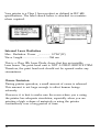
Your printer is a Class 1 laser product as defined in IEC 825
specifications. The label shown below is attached in countries
where required.
Internal Laser Radiation
Max. Radiation Power _................ 5.7 10 (W)
Wave Length ....................................... 780 nm
x
-4
This is a Class IIIb Laser Diode Assay that has an invisible
laser beam. The print head unit is NOT A FIELD SERVICE ITEM.
Therefore, the print head unit should not be opened under any
circumstance.
Ozone Emission
During printer operation, a small amount of ozone is released.
This amount is not large enough to affect human beings
adversely.
However, it is best to make sure the room where you a using
the printer has adequate circulation, especially when you are
printing a high volume of materials or using the printer
continuously over a long period of time.
vi
Contents
Introduction
Chapter 1 Setting Up
Finding a Place for the Printer.. ............................................
Unpacking ................................................................................
Assembling ..............................................................................
Turning On the Printer ..........................................................
1-2
1-5
1-8
1-21
Chapter 2 Testing and Connecting Your Printer
The Control Panel ...........................................................
Testing the Printer .....................................................................
Enhancing Print Quality
.............................................................
Connecting the Printer to Your Computer ............................
Selecting the Printer Mode . . . . . . . . . . . . . . . . . . . . . . . . . . . . . . . . . . . . . . . . .
Sharing the Printer . . . . . . . . . . . . . . . . . . . . . . . . . . . . . . . . . . . . . . . . . . .
Switching the Printer Mode ...........................................
2-2
2-6
2-11
2-16
2-23
2-25
2-26
Chapter 3 SelecType
SelecType Overview ....................................................
Using SelecType.. ....................................................................
Level 1 Options.. .....................................................................
Level 2 Options.. .....................................................................
3-2
3-6
3-13
3-22
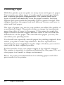
Chapter 4 Paper Handling
Choosing Paper .......................................................................
Choosing a Paper Size.. ..........................................................
Paper Feeding and Paper Delivery .......................................
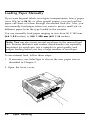
Loading Paper Manually.. ......................................................
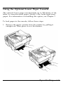
Using the Optional Lower Paper Cassette.. .........................
Using the Optional Output Tray.. ........................................
Contents
4-2
4-5
4-6
4-8
4-11
4-15
vii
Chapter 5 Maintenance and Transportation
Replacing Consumable Parts .................................................
Cleaning the Printer ...............................................................
Transporting Your Printer .....................................................
5-2
5-14
5-22
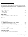
Chapter 6 Troubleshooting
Status and Error Messages.. ...................................................
Troubleshooting Directory.. ...................................................
Paper Jam Problems ................................................................
Power Supply ..........................................................................
Test Prints ................................................................................
Printing Problems ...................................................................
Problems with Graphics.. .......................................................
SelecType Problems ................................................................
Paper Handling .......................................................................
Decline in Print Quality ........................................................
Options ....................................................................................
Data Dump Mode.. .................................................................
6-2
6-9
6-11
6-21
6-22
6-23
6-27
6-29
6-31
6-34
6-38
6-41
Chapter 7 Options
Identity Cards.. ........................................................................
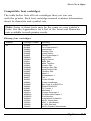
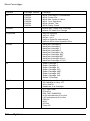
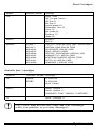
Font Cartridges.. ......................................................................
The Lower Paper Cassette Unit ............................................
The Face-Up Output Tray.. ...................................................
Optional Interface Cards.. ......................................................
Memory Options ....................................................................
Viii
Contents
7-2
7-6
7-13
7-16
7-18
7-22
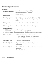
Appendix A Technical Specifications
Printer Specifications .............................................................
Interface Specifications.. ........................................................
Initialization.. ..........................................................................
Option Specifications ............................................................
Shared Printer Language .......................................................
A-2
A-8
A-15
A-16
A-18
Appendix B HP Emulation Mode
Introduction ............................................................................
SelecType Options .................................................................
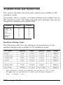
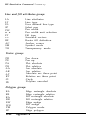
Available Fonts and Symbol Sets ........................................
Default Settings .....................................................................
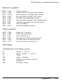
HP Emulation Command Summary ....................................
B-2
B-9
B-12
B-30
B-32
Appendix C LQ and FX Emulation Mode
Introduction ............................................................................
SelecType Options .................................................................
Available Fonts and Symbol Sets ........................................
Default Settings .....................................................................
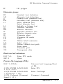
LQ and FX Emulation Command Summary ......................
C-2
C-4
Glossary
GL-1
-Index -
IN-1
C-12
C-15
C-16
Contents ix
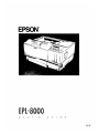
Introduction
The EPL-8000 is the latest in Epson’s advanced line of laser
printers, combining high performance and reliability with a wide
range of features. The printer combines a semiconductor laser with
the electrophotographic technology used in office copiers to give
you high-quality printing that is both fast and quiet.
The imaging system used by the printer is driven by a powerful
processor that allows the printer to compose an entire page in
internal memory before printing. The printer can manipulate the
page it holds in memory to provide you with many features not
found on other types of printers, including the ability to mix text
and graphics, create pre-defined forms, and print with a range of
fonts normally associated with typeset material.
Features
In addition to the high-quality printing and ease of operation you
expect from an Epson printer, these features make using your new
printer even easier:
High-quality, 300 dots-per-inch (dpi) printing at a speed of up
to ten pages per minute. You’ll appreciate the crisp,
professional print quality produced by the EPL-8000 and its
leading edge processing speed.
HP LaserJet III emulation for easy access to the great variety
of application software written for Hewlett-Packard@ LaserJet
printers.
Resident outline fonts to enable you to print character fonts in
a wide range of sizes. (These fonts provide the same character
widths used in Adobe PostScript™.)
Epson’s new Resolution Improvement Technology (RITech) to
enhance your graphical output and make jagged edges more
smooth.
A standard paper cassette that holds up to 250 sheets of paper.
Add the optional lower paper cassette for continuous printing
of up to 500 pages.
Introduction 1
introduction
Two Epson ESC/P® emulation modes for the compatibility with
the range of applications written for Epson 9-pin and 24-pin
printers.
1 megabyte (MB) of standard random access memory (RAM)
built-in, expandable up to 7.5MB for graphics printing and for
using three interfaces at the same time when you add an
optional interface.
Two built-in interfaces: Centronics® parallel and RS-232C or
RS-422 serial. You can also install an optional interface and use
it as a third channel for data input.
Three independent interface channels (parallel, serial, and
optional). You can connect up to three computers to your
printer and share it by using the autosense feature, which
automatically switches the printer to the channel receiving data,
or by dividing the RAM to produce a separate area for each
channel.
An intelligent emulation switching feature allows the printer to
switch automatically between PostScript emulation and another
mode based on the data received. Also, a shared printer
language feature using printer commands.
Two paper delivery methods: standard face-down delivery and
face-up delivery (with the optional face-up tray) for printing
on media requiring a straight-through paper path and for
immediate viewing of printed output.
Manual feeding directly selectable from the control panel. It is
possible to feed and print on envelopes using the manual feed
tray.
A large selection of international symbol sets to print with the
letters, characters, and symbols of various languages.
Two IC card slots for adding optional identity and font cards,
including a PostScript emulation card.
A combined photoconductive, developing, and toner unit in a
single disposable imaging cartridge for easy maintenance.
2
Introduction
Introduction
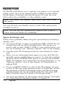
Options
Many printer options are available for your printer. For detailed
information on the installation and use of these options, see
Chapter 7. The last figure in option part numbers, represented by
an asterisk (*), varies by country. Contact your local dealer for the
part number in your country.
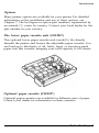
The lower paper cassette unit (C81228*)
This optional lower paper cassette unit (model L) fits directly
beneath the printer and houses the adjustable paper cassette. You
can load up to 250 sheets of A4, letter, legal, or executive-sized
paper into this cassette, bringing your total capacity to 500 sheets.
Optional paper cassette (C81223*)
Optional paper cassettes are available for different sizes of paper.
Contact your dealer for information on these cassettes.
Introduction 3
Introduction
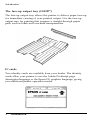
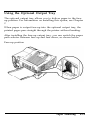
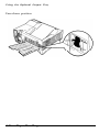
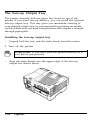
The face-up output tray (C81227*)
The face-up output tray allows the printer to deliver paper face-up
for immediate viewing of your printed output. Use the face-up
output tray for printing that requires a straight-through paper
path, such as labels and overhead transparencies.
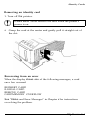
IC cards
Two identity cards are available from your dealer. The identity
cards allow your printer to use the Adobe PostScript page
description language or the Epson GL graphics language, giving
you additional printer operation modes.
4
Introduction
Introduction
Interface cards
Optional interface cards are available to supplement the printer’s
built-in parallel and serial interfaces. A complete list of available
interfaces, guidelines for choosing the right interface and other
instructions are given in Chapter 7.
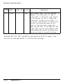
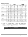
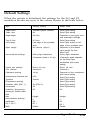
Interface cable
Epson supplies several types of interface cables. You can use any
interface cable that meets the specifications listed below. See your
computer manual for any additional requirements.
Cable
Interface
Printer side
connector
Computer side
connector
Length
C836021
C836022
Parallel
Amphenol 57
D-SUB, 25 pin
2m
C836031
C836041
Serial
D-sub, 25 pin
D-SUB, 25 pin
2m
C836051
C836061
Serial
D-sub, 25 pin
D-sub, 9 pin
2m
Introduction 5
Introduction
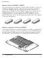
Memory chip set (C82904*, C82905*)
You can increase your printer’s current 1MB of RAM to a total of
7.5MB by installing memory chip sets and a memory expansion
board. The C82904* chip set increases the printer memory by
increments of 0.5MB, and the C82905* chip set can increase it by
2.0MB increments. You can install the 0.5MB chip sets on the
controller board or the 0K expansion board (C82206*); you can
install 2MB chip sets on the 0K expansion board only. See Chapter
7 for more information.
Memory expansion boards (C82206*)
A OK optional memory expansion board is available to supplement
your printer’s memory. You can install up to four 0.5MB chip sets
or up to three 2.0 MB chip sets on this memory expansion board.
See Chapter 7 for information on configuring optional memory.
6
Introduction
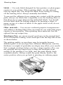
Laser Printer Precautions
This printer uses laser technology. The following list of precautions
applies whenever you open the printer cover. Even if you are
familiar with other types of printers, be sure to follow these
precautions carefully to ensure safe, efficient operation.
Be careful not to touch the fuser, which is marked by a
CAUTION HOT SURFACE label. If you have been using the
printer, the fuser can be very hot.
Avoid touching the components inside the printer unless
instructed to do so in this guide.
Protect the light-sensitive drum from exposure to light.
Avoid exposing the imaging cartridge to room light any longer
than necessary. Do not open the drum’s protective cover.
Overexposing the drum may cause abnormally dark or light
areas to appear on the printed page and reduce the service life
of the drum.
If you must expose the drum either by taking the imaging
cartridge out of the printer or by leaving the printer cover
open, cover the drum with a soft cloth or sheet of paper.
Be sure not to scratch the surface of the drum. When you
remove the imaging cartridge from the printer, always set the
cartridge on a clean, smooth surface. Also, avoid touching the
drum, since oils from your skin can permanently damage its
surface and may affect print quality.
Avoid pressing on the top of the toner cartridge. Pressing
directly on the cartridge may cause toner to spill into the
printer. If there is a spill, see Chapter 5 for cleaning
instructions.
Never force the printer’s components into place. Although the
printer is designed to be sturdy, rough handling can damage it.
Laser Printer Precautions
7
Finding Your Way Around
Chapter 1 contains information on unpacking and setting up your
printer. Be sure to read and follow these instructions first.
Chapter 2 contains information on using the control panel, testing
and connecting the printer, and sharing the printer. It also
describes how to set the printer mode and use printer selection
menus.
For detailed information on the SelecType options, see Chapter 3.
Chapter 4 contains the information on paper handling. Make sure
you read this chapter before purchasing your paper supply.
Chapter 5 gives you information on maintaining your printer.
If the printer does not operate properly or the printed results are
not what you expect, see Chapter 6 for troubleshooting tips.
Chapter 7 describes how to install the various options available for
your printer.
The appendixes contain information on technical specifications and
printer modes, including a list of available symbol sets and
character samples available for each printer mode. You will also
find a glossary of printer terms and an index.
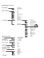
At the back of this guide is a Quick Reference card showing all
SelecType options and submenus. The SelecType menu maps
found on this card can be used as guides whenever you enter the
SelecType mode.
On the back cover foldout are illustrations identifying the different
parts of your printer. You can look at these as you set it up.
8
Finding Your Way Around
Finding Your Way Around
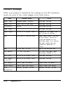
Warnings, Cautions, and Notes
WARNING S: must be followed carefully to avoid bodily
injury.
CAUTION S: must be observed to avoid damage to your
equipment.
Notes: contain important information and useful tips on the
operation of your printer.
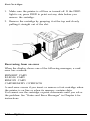
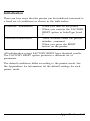
Where to Get Help for United States Users
Epson America provides local customer support and service
through a nationwide network of authorized Epson dealers and
Service Centers.
Epson also provides the following support services through the
Epson Consumer Resource Center at (800) 92243911:
Assistance in locating your nearest Authorized Epson Reseller
or Service Center
Technical assistance with the installation, configuration, and
operation of Epson products
Epson technical information library fax service
Product literature with technical specifications on our current
and new products
Sales of ribbons, supplies, parts, documentation, and accessories
for your Epson product
Customer Relations.
Finding Your Way Around
9
Chapter 1
Setting Up
Finding a Place for the Printer ................................................ 1-2
Unpacking ..................................................................................... 1-5
Assembling ..............................................................................
Installing the cleaning pad.. ...............................................
The imaging cartridge.. .......................................................
Attaching the power cord.. ................................................
Loading paper in the cassette.. ..........................................
Turning O n the Printer
1-8
1-8
1-12
1-18
1-19
............................................................. 1-21
Setting Up 1-1
Finding a Place for the Printer
Before unpacking the printer, find a suitable place to use it. Follow
the guidelines below when selecting a location.
Place the printer on a flat, stable surface.
Place it close enough to the computer or workstation for its
cable to reach.
Use a grounded outlet, one that has three holes to match the
power plug on the printer. Do not use an adapter plug.
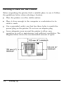
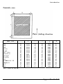
Leave adequate room around the printer to allow easy
operation as well as maintenance and sufficient ventilation. The
diagram below shows the recommended amount of space.
1-2
Setting Up
Finding a Place for the Printer
l
l
If you install the optional face-up tray, you need at least
350 mm (14 inches) of space behind the printer.
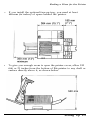
To give you enough room to open the printer cover, allow 530
mm or 21 inches from the bottom of the printer to any shelf or
surface directly above it, as shown below.
Setting Up 1-3
Finding a Place for the Printer
If you install the optional lower paper cassette, you need an
additional 70 mm (3 inches) above the printer.
CAUTIONS:
l
l
l
l
1-4
Avoid locations that are subject to direct sunlight,
excessive heat, moisture, or dust.
Avoid using an electrical outlet that is controlled by
wall switches or automatic timers. Accidental
disruption of power can wipe out valuable
information in your computer’s and printer’s memory.
Avoid using outlets on the same circuit with large
motors or other appliances that might disturb the
power supply.
Keep the entire computer and printer system away
from potential sources of interference, such as
loudspeakers or the base units of cordless telephones.
Setting Up
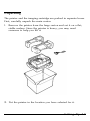
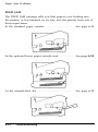
Unpacking
The printer and the imaging cartridge are packed in separate boxes.
First, carefully unpack the main carton.
1. Remove the printer from the large carton and set it on a flat,
stable surface. Since the printer is heavy, you may need
someone to help you lift it.
2. Put the printer in the location you have selected for it.
Setting Up 1-5
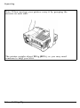
Unpacking
Note: When moving your printer, carry it by grasping the
recesses on each side.
The printer weighs about 18 kg (40 lb), so you may need
someone to help you lift it.
1-6
Setting Up
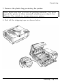
Unpacking
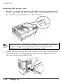
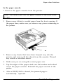
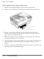
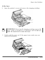
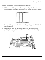
3. Remove the plastic bag protecting the printer.
Note: Make sure that you save all packing materials. You must
repack the printer in these materials whenever you ship it. See
Chapter 5 for details on transporting your printer.
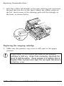
4. Peel off the shipping tape as shown below.
Setting Up 1-7
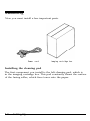
Assembling
Now you must install a few important parts.
Power cord
Imaging cartridge box
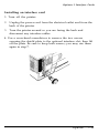
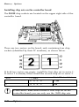
Installing the cleaning pad
The first component you install is the felt cleaning pad, which is
in the imaging cartridge box. This pad constantly cleans the surface
of the fusing roller, which fixes toner onto the paper.
1-8
Setting Up
Assembling
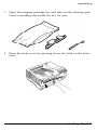
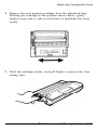
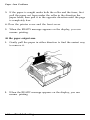
1. Open the imaging cartridge box and take out the cleaning pad.
Leave everything else inside the box for now.
2.
Open the front cover by pressing down the latch on the front
cover.
Setting Up 1-9
Assembling
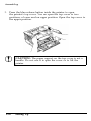
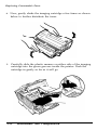
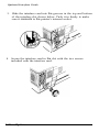
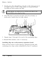
3. Press the blue release button inside the printer to open
the printer’s top cover. You can open the top cover to two
positions, a lower and an upper position. Open the top cover to
the upper position.
CAUTION: The paper support on the top cover is not a
handle. Do not use it to open the cover or to lift the
printer.
1-10
Setting Up
Assembling
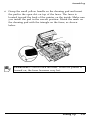
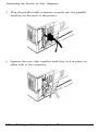
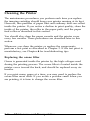
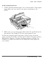
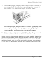
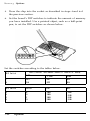
4.
Grasp the small yellow handle on the cleaning pad and insert
the pad in the open slot on top of the fuser. The fuser is
located toward the back of the printer on the inside. Make sure
you install the pad in the correct position. Match the mark on
the cleaning pad with the triangle on the fuser, as shown
below.
WARNING: Never touch the fuser. When the printer is
turned on, the fuser becomes very hot.
Setting Up
1-11
Assembling
The imaging cartridge
The imaging cartridge is the part of the printer mechanism that
forms the image and transfers it onto the paper.
CAUTION: Do not expose the drum to light any longer
than necessary. Because the drum is light-sensitive, never
expose it to lighting brighter than normal room light.
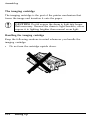
Handling the imaging cartridge
Keep the following cautions in mind whenever you handle the
imaging cartridge:
l
Do not turn the cartridge upside down.
1-12
Setting Up
Assembling
l
l
•
l
l
Do not open the drum’s protective cover, and do not scratch or
mar the surface of the drum. Also avoid touching the drum,
since oils from your skin can permanently mar its surface and
reduce print quality.
Do not expose the cartridge to direct sunlight. If you must
leave it outside the printer, first cover it with the aluminum
packing bag provided or a soft cloth.
When handling the imaging cartridge, always set it on a clean,
smooth surface.
Do not attempt to modify or take apart the cartridge. It cannot
be refilled.
Do not use a cartridge for at least one hour after moving it
from a cool to a warm environment.
Setting Up
1-13
Assembling
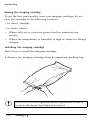
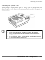
Storing the imaging cartridge
To get the best print quality from your imaging cartridge, do not
store the cartridge in the following locations:
l
In direct sunlight
l
In dusty places
•
Where salty air or corrosive gasses (such as ammonia) are
present
•
Where the temperature or humidity is high or subject to abrupt
changes.
Installing the imaging cartridge
Here’s how to install the imaging cartridge:
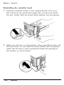
1. Remove the imaging cartridge from its aluminum packing bag.
CAUTION: Do not open the drum’s protective cover; it
protects the drum from light and contact.
1-14
Setting Up
Assembling
2. Hold the imaging cartridge upright, as shown below, and shake
the cartridge from side to side a few times to distribute the
toner.
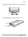
3. Hold the imaging cartridge steady and pull firmly on the
yellow tab. Remove the clear seal completely.
Setting Up
1-15
Assembling
4. After you remove the seal, gently shake the imaging cartridge
again four or five times.
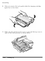
5. Make sure the printer’s front cover is open and the top cover is
open to the lower position, as shown below.
1-16
Setting Up
Assembling
6. Hold the imaging cartridge as shown below and carefully place
the plastic runners on either side of the cartridge into the green
grooves inside the printer. Then slide the cartridge forward as
far as it will go.
7. Gently press down on the printer’s top cover until it clicks into
the closed position. Then close the front cover.
CAUTION: Never transport the printer with the imaging
cartridge installed. See Chapter 5 for details on moving
the printer.
Setting Up
1-17
Assembling
Attaching the power cord
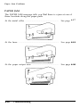
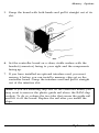
1. Before you attach the power cord, make sure the power switch
on the top of the printer is turned off. It is off when the O on
the switch is pressed down, as shown below.
WARNING: If the rated voltage of the printer and your
outlet voltage do not match, contact your dealer for
assistance. Do not plug in the power cable.
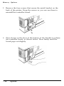
2. Insert the power cord into the socket at the back of the printer,
as shown below. Then plug the other end of the power cord
into a properly grounded outlet.
1-18
Setting Up
Assembling
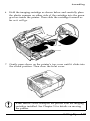
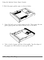
Loading paper in the cassette
The standard paper cassette holds up to 250 sheets of paper for
automatic feeding. See Chapter 4 if you need more information on
paper handling. To load paper into the cassette, follow these steps:
1. Remove the paper cassette by pulling it straight out.
2.
Take a stack of paper and fan it thoroughly. Tap the edges of
the paper on a flat surface to even up the stack.
Setting Up
1-19
Assembling
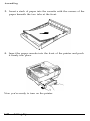
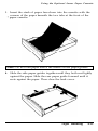
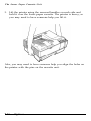
3. Insert a stack of paper into the cassette with the corners of the
paper beneath the two tabs at the front.
4. Insert the paper cassette into the front of the printer and push
it firmly into place.
Now you’re ready to turn on the printer.
1-20
Setting Up
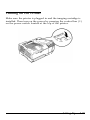
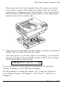
Turning on the Printer
Make sure the printer is plugged in and the imaging cartridge is
installed. Then turn on the power by pressing the vertical bar ( I )
on the power switch located at the top of the printer.
Setting Up
1-21
Turning On the Printer
The indicator lights on the control panel light briefly when you
turn on the printer. The following messages appear as the printer
performs a series of internal tests and warms up:
CAUTION:
• Do not open the printer’s covers while the printer is
warming up or printing.
l After you turn off the printer, always wait at least five
seconds before turning it back on.
It takes approximately 70 seconds for the printer to complete its
power-on routine. When the READY message appears, you can
use the printer. If the display remains blank, see Chapter 6 for
troubleshooting information.
Chapter 2 tells you how to test your printer, connect it to a
computer or computers, and begin using it with software.
1-22
Setting Up
Chapter 2
Testing and Connecting Your Printer
The Control Panel ...................................................................
Display .................................................................................
Indicator lights ....................................................................
Buttons .................................................................................
2-2
2-2
2-3
2-4
Testing the Printer ..................................................................
Running a test print ...........................................................
Printing a status sheet ........................................................
Printing a font sample ........................................................
2-6
2-6
2-8
2-10
Enhancing Print Quality ........................................................
Adjusting the print density ...............................................
Resolution Improvement Technology ...............................
2-11
2-11
2-13
Connecting the Printer to Your Computer ..........................
Choosing an interface .........................................................
Connecting the parallel interface ......................................
Connecting the serial interface.. ........................................
Testing the computer-to-printer connection ...................
2-16
Selecting the Printer Mode.. ..................................................
Using printer selection menus ...........................................
2-23
2-23
Sharing the Printer ,................................................................
2-25
Switching the Printer Mode ..................................................
Intelligent Emulation Switch (IES). ...................................
Shared Printer Language ....................................................
2-26
2-26
2-26
Testing and Connecting Your Printer
2-1
2-16
2-17
2-19
2-22
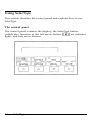
The Control Panel
The printer control panel gives you easy control over most
common printer operations. The panel is made up of three
elements: a liquid crystal display, indicator lights, and buttons. The
display and indicator lights tell you the current status of the
printer, and you use the buttons to select printer settings and
functions.
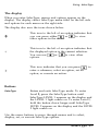
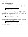
Display
The display shows the followings:
l
l
l
Status messages, such as WARMING UP, indicate the printer’s
current status.
Error messages, such as PAPER OUT, identify maintenance
procedures you must perform or of error conditions you need
to correct.
SelecType options, such as MODE ASSIGN, allow you to
control the printer mode, font selection, paper handling, and
many other printer functions.
For a complete list of status and error messages, see Chapter 6.
For information on SelecType, see Chapter 3.
2-2
Testing and Connecting Your Printer
The Control Panel
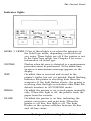
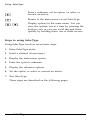
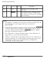
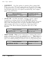
Indicator lights
LEVEL 1, LEVEL 2 One of these lights is on when the printer is in
the SelecType mode, depending on which level
you enter. These lights are off if the printer is not
in the SelecType mode. See Chapter 3 for more
information on SelecType.
CONTINUE
Flashes when an error is detected or a maintenance
procedure must be performed. At the same time,
an error or maintenance message appears on the
display.
FEED
On when data is received and stored in the
printer’s buffer but not yet printed. Rapid flashing
indicates the printer is receiving data from the
computer. If the light flashes slowly, the printer is
receiving data through an interface other than the
default interface in AUTOSENSE mode.
MANUAL
On when the printer is set to feed paper manually
only. When this light is off, the printer feeds the
paper from the cassette.
ON LINE
On when the printer is on line, indicating the
printer can receive and print data. When the
printer is off line, this light is off. The light
flashes as the system switches between on-line
and off-line status.
Testing and Connecting Your Printer
2-3
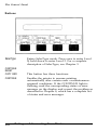
The Control Panel
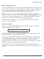
Buttons
SelecType
CONTINUE
RESET
COPY END
CONTINUE
2-4
Enters SelecType mode. Press once to enter Level
1; hold down to enter Level 2. For a complete
description of SelecType, see Chapter 3.
This button has three functions:
Enables the printer to resume printing
automatically after certain error or maintenancerequired conditions. If the CONTINUE light is
flashing, read the corresponding status or error
message on the display and correct the problem as
described in Chapter 6, which has a complete list
of status and error messages.
Testing and Connecting Your Printer
The Control Panel
RESET
Cancels some settings made with SelecType or
software commands. When you hold down this
button for several seconds, RESET appears on the
display and all settings return to their previouslysaved values. The printer finishes printing the
page in progress at the moment this button is
pressed, but it erases all remaining data. If you
press
or
, the printer returns to its
previous status without printing data. If you
continue to hold down this button after RESET
appears, INITIALIZE appears on the display and
the printer settings return to the settings in effect
at power on. See Chapter 3, SelecType.
COPY END
Cancels the remaining copies during multi-copy
printing. This button is effective only when the
printer is off line.
FEED
MANUAL
If the FEED light is lit, press ON LINE to take the
printer off line. Then press FEED to print out data
in the printer’s memory. If you are using more
than one channel, you can print data received by
each channel.
To select manual paper feeding. Press this button
when the FEED light is off or flashing slowly and
the printer is on line.
ON LINE
Switches the printer between-on line and off-line
status. This switch is disabled when the printer is
in SelecType mode.
Testing and Connecting Your Printer
2-5
Testing the Printer
The printer has four built-in print tests: two test prints, a status
sheet, and a font sample. These tests let you check the operation
of your printer and obtain information on printer settings.
Before running a test, make sure you have removed all packing
materials from the printer and installed all printer parts, as
described in Chapter 1. You do not need to connect the printer to
a computer to run these tests.
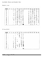
Running a test print
The test print option allows you to print two patterns: pattern 1
consists of vertical lines and pattern 2 consists of horizontal lines.
Follow these steps to run the test print.
1.
Turn on the printer as described in Chapter 1.
2. Hold down the SelecType button until the LEVEL 2 indicator
light comes on.
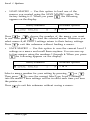
3. Next, TEST PRINT should appear on the display. If it does not,
press
or
until it does.
If you cannot find the TEST PRINT option, you probably did
not hold down the button long enough to enter Level 2. If the
LEVEL 1 indicator is on, press the SelecType button once to
exit SelecType and repeat step 2.
2-6
Testing and Connecting Your Printer
Testing the Printer
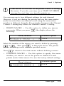
4. Press
once. The display reads as follows:
5. To run the test, press
once more. The printer prints a test
pattern of vertical lines and outputs the page face-down in the
top exit tray.
CAUTION: Never open the printer’s covers during
printing.
Part of a typical pattern 1 test print is shown below:
Testing and Connecting Your Printer
2-7
Testing the Printer
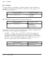
After printing the page, the printer displays TEST PRINT. To print
the second test print pattern, follow these steps:
1. Press
once.
2. Change the test pattern number by pressing
once.
3. Press
or
to print second pattern.
After you print the test pattern, press the SelecType button twice
to exit SelecType.
If the test does not print properly, see Chapter 6 for
troubleshooting information.
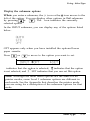
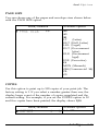
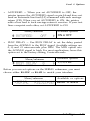
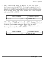
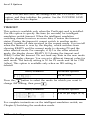
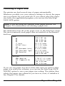
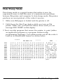
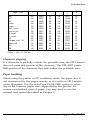
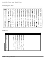
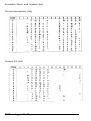
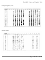
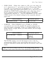
Printing a status sheet
In addition to the test print patterns, you can print a status sheet
that lists the current printer settings.
lists the printer’s current settings. If you
change the macro number setting for the LOAD MACRO option
in the SYSTEM CONFIG submenu, the status sheet prints out
the new macro settings. MACRO 0 is the factory default setting.
Note: The status sheet
2-8
Testing and Connecting Your Printer
Testing the Printer
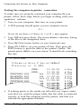
Follow these steps to print the status sheet:
1. Press SelecType once to enter SelecType Level 1.
Note: If you have already chosen the INDIVIDUAL mode in
SelecType and have set up more than one channel, the following
option appears on the display (The display shows available
channels only):
Press any arrow button to choose your channel; then go on to
step 2.
2. Press
until STATUS SHEET appears on the display.
3. Press
twice to print the status sheet.
4. Press the SelecType button twice to exit SelecType.
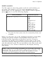
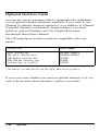
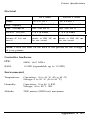
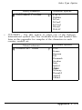
A portion of the status sheet printout is shown below.
STATUS SHEET
EPSON
Printer Configuration
Installed Memory : 4.5Mbytes
Memory Share
: AUTOSENSE
Auto Continue
: OFF
standby
: DISABLE
Form Length
: 64
System Configuration
Top Offset
: 0
Full Print
: 0
Load Macro
: 0
Symbol set
Controller Version : 21.04
CH Time out
: 60
Total Printed Count: 552216
:ON
: Roman-8
Left Offset
: 0
Memory Left
: 4110Kbytes
Power On Macro : 0
Testing and Connecting Your Printer
2-9
Testing the Printer
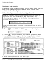
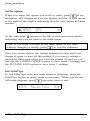
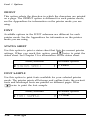
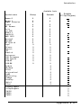
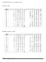
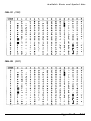
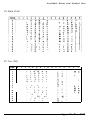
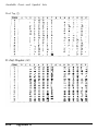
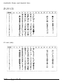
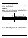
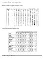
Printing a font sample
In addition to the test print patterns and the status sheet, you can
print a font sample that shows samples of the various fonts
available in the selected printer mode.
1. Press SelecType once to enter SelecType Level 1.
Note: If you have already chosen the INDIVIDUAL mode in
SelecType, and have set up more than one channel, the
following option appears on the display (the display shows
available channels only):
Press any arrow button to choose your channel; then go on to
step 2.
2. Press
until FONT SAMPLE appears on the display.
Press
twice to print the font sample. The printer takes
several seconds to compose the font sample before it starts
printing. A portion of the printout is shown below.
4. Press SelecType twice to exit SelecType.
2-10
Testing and Connecting Your Printer
Enhancing Print Quality
When your print quality is not satisfactory, be sure that you are
using smooth, high-quality paper. For information on choosing
paper, see Chapter 4.
If you still want to improve print quality, try adjusting the print
density or changing the Resolution Improvement Technology
setting.
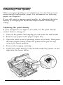
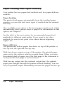
Adjusting the print density
If your test print is too light or too dark, use the print density
control knob to change it.
1.
Turn off the printer and unplug its cord from the wall outlet.
2.
Remove any paper in the paper output tray.
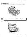
3.
Open the front cover by pressing down on its latch. Then press
the blue release button inside the printer and open the top
cover to its lower position.
4.
Remove the imaging cartridge.
5.
Locate the green density control knob inside the printer on the
right side, as shown below.
Testing and Connecting Your Printer
2-11
Enhancing Print Quality
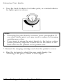
6.
Turn the knob clockwise for darker print, or counterclockwise
for lighter print as shown.
Notes:
Increasing the print density increases toner consumption. If
you select darker print, you may need to replace the imaging
cartridge more often.
If you want to return the print density to the factory setting
(center position), align the vertical line on the center of the
knob with the dot printed on the printer case.
l
l
7. Reinsert the imaging cartridge and close the printer’s covers.
8.
Run the test print to check the new print density. See
“Running a test print,” earlier in this chapter.
2-12
Testing and Connecting Your Printer
Enhancing Print Quality
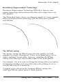
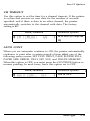
Resolution Improvement Technology
Resolution Improvement Technology (RITech) is Epson’s new
printer technology that produces smoother and crisper lines, text,
and graphics.
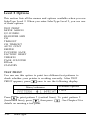
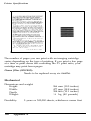
The illustration below shows an enlarged sample of a curve printed
with conventional laser technology and the same curve printed
with RITech.
The RITech setting
The factory setting for RITech gives the best quality text and
graphics for nearly all purposes. It does not require you to set or
adjust anything. Occasionally, however, adjusting the RITech
setting with SelecType may further improve the print quality.
For example, you may want to change the setting after you replace
an imaging cartridge or if you notice that your printing is not as
smooth and crisp as it should be.
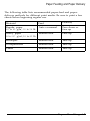
To guide you in choosing the optimum RITech setting, the
SelecType RITech option prints a check pattern.
Testing and Connecting Your Printer
2-13
Enhancing Print Quality
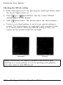
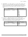
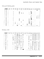
Checking the RITech setting
1. Enter SelecType Level 2 by pressing the SelecType button until
the Level 2 light comes on.
2.
Press
or
until RITech and the current RITech
setting appear on the display.
3.
Press
4.
Look at your check pattern to see if your current setting is
correct. The check pattern is a rectangle with a pattern inside
it, as shown below. When the RITech setting is best, you
cannot see the pattern inside the rectangle.
three times. The printer prints the check pattern.
Incorrect
Correct
Note: RITech may not improve graphics that include gray
shading or a screen pattern. If you are printing such graphics,
you may want to turn RITech off.
2-14
Testing and Connecting Your Printer
Enhancing Print Quality
Changing the RITech setting
To change the RITech setting, use SelecType Level 2. You can
select LIGHT, MEDIUM (the factory setting), HEAVY, or OFF. (If
necessary, see Chapter 3 for full instructions on using SelecType.)
If your check pattern is too heavy, change the setting to LIGHT; if
it is too light, change the setting to HEAVY; if you are printing
gray shading or screen patterns, change the setting to OFF.
To change your RITech setting, follow these steps:
1.
Enter SelecType Level 2 by pressing the SelecType button until
the Level 2 light comes on.
2.
Press
3.
Press
once and then press
or
until your
desired setting (LIGHT, MEDIUM, HEAVY, or OFF) appears
on the display.
4.
Press
twice to set the new setting and print a new check
pattern using the new RITech setting.
5.
Look at the new check pattern to see if it is improved. If you
wish, save the new setting by pressing
once to return to
the main menu, then pressing
or
until P CONFIG
SAVE appears on the display, then pressing
twice.
or
until RITech appears on the display.
If the pattern still needs to be improved, you probably need to
change the print density setting. For a darker (HEAVY) RITech
setting, make the print density lighter and vice versa. See
“Adjusting the print density” earlier in this chapter for
instructions.
Note: Do not change the print density unless it is necessary.
Changing the print density affects all text and graphics, so check
the new setting by printing several pages.
Testing and Connecting Your Printer
2-15
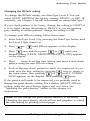
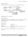
Connecting the Printer to Your Computer
For the printer to receive information from your computer, they
must be set up so they can communicate properly. This requires
the correct interface cable and communication settings. Your
printer comes with the following built-in interfaces:
l
Centronics-compatible parallel
l
RS-232C/RS-422 serial
The interfaces are located as shown below.
Parallel
interface
Serial interface
Several optional interface cards are also available for use with the
printer. See Chapter 7 for details on using these options.
Choosing an interface
To connect the printer to your computer, first determine whether
you require a parallel or serial connection. If your computer
provides both types of connection, use the parallel interface for the
printer and leave the serial port on your computer free for devices
such as modems. If you are in doubt about which type of
connection to use, consult your dealer.
2-16
Testing and Connecting Your Printer
Connecting the Printer to Your Computer
Your printer is initially set up for parallel communication.
If you are using a parallel interface, you should be able to connect
your computer to the printer with a properly shielded twisted-pair
cable and not change any factory settings.
If you decide to use a serial interface, you may need to use
SelecType to change some of the printer’s serial settings, such as
baud rate or parity, to match the computer’s settings. See Chapter
3 for details on using SelecType to set up the printer’s serial
interface settings.
If you plan to use an optional interface, see Chapter 7 for details.
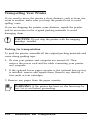
Connecting the parallel interface
If you want to use the printer’s standard parallel interface, make
sure you have a shielded twisted-pair cable suitable for a
Centronics-compatible interface.
Follow these steps to connect the parallel interface:
1.
Turn off both your printer and computer. Then unplug the
printer’s power cord from the electrical outlet.
Testing and Connecting Your Printer
2-17
Connecting the Printer to Your Computer
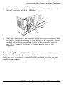
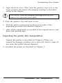
2. Plug the parallel cable connector securely into the parallel
interface on the back of the printer.
3.
Squeeze the wire clips together until they lock in place on
either side of the connector.
2-18
Testing and Connecting Your Printer
Connecting the Printer to Your Computer
4. If your cable has a grounding wire, connect it to the printer’s
ground connector as shown below.
5.
Plug the other end of the parallel cable into your computer and
fasten the connector screws to the interface, if necessary. Some
parallel cables have grounding wires at the computer end as
well. If so, connect this wire to the ground screw on the
computer.
Connecting the serial interface
If you want to use the printer’s standard serial interface, make sure
that you have a properly shielded cable and that it is the correct
one for your printer.
Testing and Connecting Your Printer
2-19
Connecting the Printer to Your Computer
Follow these steps to connect the serial interface:
1.
Turn off both the printer and computer. Then unplug the
printer’s power cord from the electrical outlet.
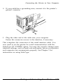
2. Plug the serial cable connector securely into the serial interface
on the back of the printer.
3. Use a screwdriver to fasten the screws of the connector, if
required.
2-20
Testing and Connecting Your Printer
Connecting the Printer to Your Computer
4. If your cable has a grounding wire, connect it to the printer’s
ground connector.
5. Plug the other end of the cable into your computer.
Fasten the connector screws to the interface, if necessary.
This completes the connection of the serial interface cable. You
now need to set the printer for serial communication with the
SelecType I/F CONFIG option. You may also need to change some
interface settings, such as baud rate and parity, before your printer
and computer can communicate properly. See Chapter 3 for
instructions on using SelecType.
Testing and Connecting Your Printer
2-21
Connecting the Printer to Your Computer
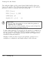
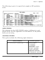
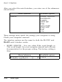
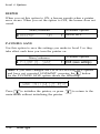
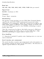
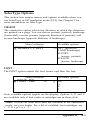
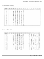
Testing the computer-to-printer connection
To make sure you properly connected your computer to your
printer, follow these steps before you begin working with your
application software:
1. Turn on your computer; then turn on your printer.
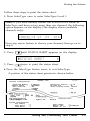
2. A DOS prompt should apear on your computer screen.
C:>
If you do not have a C drive, A: > or B: > may appear.
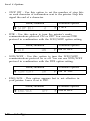
3. Type DIR and press Enter. The screen shows a directory listing
of the files in the designated drive.
4. Press the Print Screen button on your keyboard once.
5. Press ON LINE to set your printer off line. Then press the
FEED button to print the data in the printer’s buffer. The
printer prints what is on your screen. It should look something
like this:
C:\EPL>dir
Volume in drive C has no l a b e l
D i r e c t o r y o f C : \EPL
•
.
.
PRNTWIN3
REABWIN3
READWIN2
PRNTWIN2
BAT
BAT
BAT
BAT
<DIR>
<DIR>
11-20-90
11-20-90
11-20-90
166
11-20-90
104
104 11-20-90
11-20-90
166
6:26p
6:26p
2:09p
2:07p
2:52p
2:53p
6. If nothing prints or the results are not what you expect, make
sure that you used the proper cable, that the cable is connected
securely to both the computer and the printer, and that you
selected the appropriate interface.
2-22
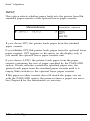
Testing and Connecting Your Printer
Selecting the Printer Mode
Your printer comes with the following resident printer modes:
l
l
l
HP LaserJet series III
Epson LQ-2500
Epson FX-800/1000 (FX-86e/286e)
Other printer modes are available with the optional identity cards
described in Chapter 7.
You use the SelecType MODE ASSIGN option to select the printer
mode. The default is HP LaserJet series III.
If you plan to use more than one channel with your printer, you
can assign the same or a different printer mode to each channel,
using the SelecType MODE ASSIGN option. See Chapter 3 for
details on using SelecType to set the printer mode for each
channel.
The printer mode you select affects the following selections
you make when using your printer. See the Appendixes for
information on each mode.
l
l
l
l
The printer you select from your application software’s printer
selection menu. See the next section, “Using printer selection
menus,” for selection priority.
Available symbol sets and fonts, including the optional cards
and cartridges.
Some features concerning paper handling, such as bin selection
or printable area.
Other methods besides SelecType are available for selecting
and changing the printer mode. See “Switching the Printer
Mode” later in this chapter.
Using printer selection menus
Once you’ve set up the printer, you start using it with your
application software program by choosing a printer name from the
program’s printer selection menu.
Testing and Connecting Your Printer
2-23
Selecting the Printer Mode
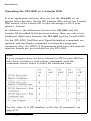
HP LaserJet III emulation mode
When your printer is in HP LaserJet III (LJ-3) mode, the factory
setting, select one of the following drivers from your program’s
printer selection menu:
HP
HP
HP
HP
HP
HP
HP
HP
LaserJet IIISi™*
LaserJet IIIP™
LaserJet series III™
LaserJet IIP™
LaserJet series II™
LaserJet Plus™
LaserJet 500™
LaserJet™
*
See Appendix B for information on the difference between the
EPL-8000 and the IIISi.
If none of the above printers is listed among your program’s
options, select any printer model that uses the HP Printer
Command Language (PCL).
Epson LQ and FX emulation modes
When your printer is in the Epson LQ or FX printer mode, select
one of the following drivers from your program’s printer selection
menu:
LQ-2500
LQ-1050/850
FX-1000/800 (286e/86e)
FX-85
LQ-1000/800 (expanded ESC/P) FX-80
LQ-500
LQ-1500 (with version 2 ROM)
LQ printer
If none of the printers listed are available from your program,
choose the first available of the following: RX, Epson printer,
Standard printer, or Draft printer.
2-24
Testing and Connecting Your Printer
Sharing the Printer
You can connect your printer to as many as three different
computers at the same time using any combination of the parallel,
serial, and optional interfaces. Simply connect interface cables from
the computers to the interfaces.
If you use the default printer mode LJ-3 for all the interfaces,
that’s all you need to do unless you need to change serial interface
settings. If you wish, however, you can choose different
printer modes for each interface, and you can allocate a separate
part of the printer’s memory for each interface.
Your printer receives data from the computers through the
following channels:
Channel P is the parallel interface.
Channel S is the serial interface.
Channel O is the optional interface.
See Chapter 7 for information on the optional interfaces.
If you are sharing your printer, see the section on the CH setting
on Page 3-32 for full information on the possible settings.
Testing and Connecting Your Printer
2-25
Switching the Printer Mode
Your printer comes with the following printer modes:
l
l
l
HP LaserJet III (LJ-3)
Epson LQ (LQ)
Epson FX (FX)
Also, the following modes are available on optional identity cards.
You can use only one of them at a time because your printer has
only one identity card slot (Slot A.)
• PostScript (PS)
• HP GL (EPSON GL)
If you use different printer modes with different application
programs, you have three different ways to switch from one
printer mode to another. (Remember that PostScript and Epson GL
require optional identity cards.)
l
l
l
Intelligent Emulation Switching (IES)—switches between
PostScript and one other mode
SelecType
Shared printer language (SPL)—uses printer commands to
switch from any mode to any other, except out of Epson GL.
Intelligent Emulation Switch (IES)
SelecType Level 2 has three Intelligent Emulation Switching modes:
PostScript/LaserJet III, PostScrip/LQ, and PostScript/FX. When
you install the optional PostScript card and select one of the IES
settings with MODE ASSIGN, the printer switches automatically
between the two modes, depending on the data it receives. See
MODE ASSIGN in Chapter 3 for more information.
Shared Printer Language
Shared printer language is designed for experienced users and
programmers. You can find full information on this function at the
end of Appendix A.
2-26
Testing and Connecting Your Printer
Chapter 3
SelecType
SelecType Overview.. .........................................................................
Level 1 functions ............................................................................
Level 2 functions ............................................................................
3-2
3-3
3-4
Using SelecType.. ................................................................................
The control panel.. ..........................................................................
The display.. ....................................................................................
Buttons.. ...........................................................................................
Steps to using SelecType ...............................................................
3-6
3-6
3-7
3-7
3-8
Level 1 Options ................................................................................
INPUT.. ..........................................................................................
PAGE SIZE ....................................................................................
COPIES ..........................................................................................
ORIENT.. .......................................................................................
FONT.. ...........................................................................................
STATUS SHEET ...........................................................................
FONT SAMPLE ............................................................................
SUB CONFIG.. ..............................................................................
SYSTEM CONFIG.. ......................................................................
3-13
3-14
3-15
3-15
3-16
3-16
3-16
3-16
3-17
3-17
Level 2 Options ................................................................................
TEST PRINT .................................................................................
MODE ASSIGN.. ..........................................................................
I/F CONFIG.. ................................................................................
RX-BUFFER SIZE .........................................................................
CH ..................................................................................................
TIMEOUT.. ....................................................................................
CH TIMEOUT ..............................................................................
AUTO CONT ...............................................................................
BEEPER.. ........................................................................................
P-CONFIG SAVE .........................................................................
FACTORY RESET.. ......................................................................
VERSION.. .....................................................................................
PAGE COUNTER.. .......................................................................
RITech.. ..........................................................................................
STANDBY.. ...................................................................................
3-22
3-22
3-23
3-24
3-30
3-32
3-34
3-35
3-35
3-36
3-36
3-37
3-37
3-38
3-38
3-38
SelecType 3-1
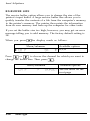
SelecType Overview
The SelecType function on the printer control panel allows you to
control most of the printer’s functions, such as printing test pages,
selecting paper size, and changing the printer’s configuration.
SelecType is divided into two levels: Level 1 and Level 2. Level 1
contains everyday printing and font selection functions, and Level
2 contains functions that you are less likely to change frequently,
such as printer mode and printer configuration.
Your application program may send printer commands that
override the SelecType settings. If you are not getting the results
you expect, check your application software settings.
Note: New SelecType settings are in effect only until you turn
off the printer unless you save them with the Level 1 SYSTEM
CONFIG option or the Level 2 P-CONFIG SAVE option
described later in this chapter.
To view the current SelecType settings, print the status sheet as
described in Chapter 2.
At the back of this guide, you’ll find a Quick Reference Card that
includes a map of all the SelecType menus and options.
3-2
SelecType
SelecType Overview
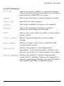
Level 1 functions
Selects the serial, parallel, or optional channel
when you have set up more than two interfaces
and used the INDIVIDUAL mode.
Selects the standard or optional paper cassette.
Specifies the size of paper.
Selects the number of copies to be printed.
Selects the printing orientation: portrait
(vertical) or landscape (horizontal).
Selects one of the fonts available in the current
printer mode.
Prints a report listing the current printer
settings.
Prints a sample of the fonts available in the
current printer mode.
Defines the printer’s subconfiguration;
depending on the printer mode, controls such
features as symbol set and number of text lines.
Defines the printer’s system configuration;
saves Level 1 settings, displays the amount of
memory remaining, changes top and left offsets,
and enables printing of complex pages.
SelecType 3-3
SelecType Overview
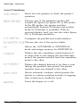
Level 2 functions
Prints two test patterns to check the printer’s
operation.
Chooses one of the emulation modes: HP
LaserJet III, Epson LQ, Epson FX, or IES modes.
In the IES modes, the printer switches
automatically between PostScript and another
mode (if PostScript is available). With an
optional identity card, you can also select Epson
GL or PostScript emulation.
Configures the parallel and serial interfaces.
: Chooses the size of the receive buffer.
Selects the AUTOSENSE or INDIVIDUAL
mode and assigns memory for INDIVIDUAL.
Defines the auto emulation switch timeout; if
no more data is sent during the specified time
period, the printer switches from one emulation
mode to the other.
Defines the channel timeout; if no data is sent
during the specified time period, the printer
switches from one channel to the other.
Selects automatic continue, which permits the
printer to continue printing instead of stopping
after certain error conditions occur.
Turns the beeper on or off.
3-4
SelecType
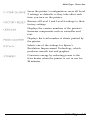
SelecType Overview
Saves the printer’s configuration; saves all Level
2 settings as defaults so they take effect each
time you turn on the printer.
Returns all Level 1 and Level 2 settings to their
factory settings.
Displays the version numbers of the printer’s
firmware components such as controller and
font.
Displays the total number of sheets printed by
the printer.
Selects one of the settings for Epson’s
Resolution Improvement Technology, which
produces smooth text and graphics.
Conserves energy by reducing power to the
fixer heater when the printer is not in use for
30 minutes.
SelecType 3-5
Using SelecType
This section describes the control panel and explains how to use
SelecType.
The control panel
The control panel contains the display, the SelecType button
(which also functions as the left arrow button,
six indicator
lights, and four arrow buttons.
3-6
SelecType
Using SelecType
The display
When you enter SelecType, menus and options appear on the
display. The display shows SelecType menu titles on the left side
and options for each menu on the right side.
The display also uses the icons shown below:
This icon to the left of an option indicates that
you can press either
or
to view
other options in the menu.
This icon to the left of an option indicates that
the displayed option is the current selection.
You can use
or
to view other
options.
This icon indicates that you can press
enter a submenu, select an option, set an
option, or execute an action.
to
Buttons
SelecType
Enters and exits SelecType mode. To enter
Level 1, press the SelecType button until
SelecType LEVEL 1 appears on the display and
the LEVEL 1 light comes on. To enter Level 2,
hold the button down longer until SelecType
LEVEL 2 appears on the display and the LEVEL
2 light comes on.
Use the arrow buttons to move through menus and to select,
display, set, or execute SelecType options.
SelecType 3-7
Using SelecType
Enter a submenu, set an option, or select or
execute an action.
Return to the main menu or exit SelecType.
Display options in the same menu. You can
view the options one at a time by pressing the
buttons once or you can scroll through them
quickly by holding down one of these arrows.
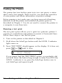
Steps to using SelecType
Using SelecType involves seven basic steps:
1.
Enter SelecType mode.
2.
Select a channel (if necessary).
3.
Display the main menu option.
4.
Enter the option’s submenu.
5.
Display the submenu options.
6.
Set the option or select or execute an action.
7.
Exit SelecType.
These steps are described on the following pages.
3-8
SelecType
Using SelecType
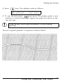
Enter SelecType mode
To enter SelecType, just press the SelecType button. SelecType has
two levels; the level you enter depends on how long you press the
button. Press and release the SelecType button to enter Level 1, or
press and hold the SelecType button to enter Level 2.
When you enter Level 1, the display shows SelecType LEVEL1
briefly. Then one of the Level 1 main menu options appears. When
you enter Level 2, the display shows SelecType LEVEL2 briefly.
Then, one of the Level 2 main menu options appears.
The following discussion uses the INPUT option in SelecType
Level 1 as an example.
Select a channel
If you are using INDIVIDUAL mode, SelecType Level 1 begins
with the display shown below.
The display shows the available channels only. See Chapter 2 for
more information on sharing the printer.
If you are using AUTOSENSE mode, remember the channel (S, P,
or O) displayed before you enter SelecType. All Level 1 settings
are stored in that channel. If you want to save the settings
permanently, store them in a macro and choose that macro as the
poweron macro. See pages 3-20 and 3-21.
The printer stores the settings for each channel separately. The
settings you choose in one channel do not affect the settings in the
other.
SelecType 3-9
Using SelecType
Display the main menu option
When you are in the SelecType main menu, an
icon precedes
the names of each of the main menu options on the display. In
many cases, the display also shows the current setting, as shown
below.
The
icon indicates that you can use
or
to display the
other options on the main menu. The
icon at the right of the
display indicates that you can enter the submenu by pressing
Options with many submenus, such as SUB CONFIG, may
display only the main option.
Enter the options submenu
Most main menu options have at least one submenu. To enter an
option’s submenu, just press
indicates the option is selected, and in some cases a message
(SET, EXEC, or PRINT) appears to the right of the option shown.
3-10
SelecType
Using SelecType
Display the submenu options
When you enter a submenu, the
icon or the icon moves to the
left of the option. You can display other options in that submenu
by pressing
or
. The icon indicates the currently
selected option.
In the INPUT submenu, you can display any of the options listed
below.
OPT appears only when you have installed the optional lower
paper cassette.
Press
or
to move to the option you want to set.
indicates that the option is selected,
indicates that the option
is not selected, and
SET indicates that you can set the option.
Note: Although the main menu options are the same for all
printer modes, some Level 1 submenu options are different in
each mode. See the Appendix that describes the printer mode
you are using for a description of the submenu options for that
mode.
SelecType
3-11
Using SelecType
Set the option
When you reach the option you want to select, press
to set
the option. SET disappears from the display and the
icon moves
to the right of the display indicating that the new option has been
selected.
At the same time,
moves to the left of the main menu option,
indicating that you are back in the main menu.
Note: If you want to return to the main menu at any time
without changing a setting, press
to exit the submenu.
Once you set an option, the setting remains in effect until you
change it again or turn off the printer. If you want a setting to
remain in effect even when you turn the printer off and on, you
can use the SYSTEM CONFIG option to save Level 1 settings and
the PCONFIG SAVE option to save Level 2 settings.
Exit SelecType
To exit SelecType from any main menu or submenu, press the
SelecType button as many times as necessary. When you see the
following message, press
one more time to exit:
3-12
SelecType
Level 1 Options
This section lists all the menus and options available when you use
SelecType Level 1. Most menus and options are the same in the
different printer modes. However, some have a different function
for each mode. These menus are listed in the Appendix that
describes the printer mode. See the Quick Reference Card at the
back of this manual for a map of all SelecType menus and options.
When you enter SelecType Level 1, you see one of these options:
Note: If you have set the CH option in Level 2 to INDIVIDUAL,
the SelecType display shows CANCEL: S: I’: 0: whenever you
enter Level 1. To select a channel, press the arrow that
corresponds to the channel you plan to use. After you select the
channel, one of the main menu options listed above appears on
the display.
If you are using AUTOSENSE mode, remember the channel (S, P,
or O) displayed before you enter SelecType. All Level 1 settings
are stored in that channel. If you want to save the settings
permanently, store them in a macro and choose that macro as the
poweron macro. See pages 3-20 and 3-21.
SelecType
3-13
Level 1 Options
INPUT
This option selects whether paper feeds into the printer from the
standard paper cassette or the optional lower paper cassette.
Menu/submenu
Available options
STD
OPT
AUTO
If you choose STD, the printer loads paper from the standard
paper cassette.
If you choose OPT, the printer loads paper from the optional lower
paper cassette. OPT appears as an option on the display only if
you install the optional lower paper cassette unit.
If you choose AUTO, the printer loads paper from the paper
cassette containing the size of paper specified by the PAGE SIZE
option. If both cassettes contain the specified paper size, the
printer loads paper from the standard paper cassette until it is
empty, then switches to the optional lower paper cassette.
If the paper in either cassette does not match the paper size set
with the PAGE SIZE option, the printer returns a paper size error.
See Chapter 6 for the information on recovery.
3-14
SelecType
Level 1 Options
PAGE SIZE
You can choose any of the paper and envelope sizes shown below
with the PAGE SIZE option.
Menu/submenu
Available options
A4
A5
B5
(Letter)
LT
HLT (Half Letter)
LGL (Legal)
GLT (Government
letter)
GLG (Government
legal)
EXE (Executive)
F4
MON (Monarch)
C10 (Commercial 10)
DL
C5
COPIES
Use this option to print up to 999 copies of your print job. The
factory setting is 1. If you select a number greater than one, the
display keeps count of the number of copies completed and the
current setting. For example, if you set the COPIES option to 10
and five copies have been printed, the display shows 5/10.
Menu/submenu
Available options
1 to 999
SelecType
3-15
Level 1 Options
ORIENT
This option selects the direction in which the characters are printed
on a page. The ORIENT option is different for each printer mode;
see the Appendixes for information on the printer mode you are
using.
FONT
Available options in the FONT submenu are different for each
printer mode. See the Appendixes for information on the printer
mode you are using.
STATUS SHEET
Use this option to print a status sheet that lists the current printer
settings. When you reach this option, press
twice to print the
status sheet. See Chapter 2 for information on the status sheet.
Menu/submenu
Available options
> PRINT
FONT SAMPLE
Use this option to print fonts available for your selected printer
mode. The printer prints all bit-map and outline fonts; the portrait
fonts and landscape fonts are printed on different pages. Press
twice to print the font sample.
Menu/submenu
Available options
> PRINT
3-16
SelecType
Level 1 Options
The following is part of a typical font sample in HP emulation
mode.
SUB CONFIG
The submenu for the SUB CONFIG option is different in each
printer mode. See the Appendixes for information on the printer
mode you are using.
SYSTEM CONFIG
This option includes the following eight submenus:
Menu/submenu
Available options
FULL PRINT
T-OFFSET
L-OFFSET
MEMORY LEFT
LOAD MACRO
SAVE MACRO
DELETE MACRO
POWERON MACRO
SelecType
3-17
Level 1 Options
Each submenu is explained below.
l
FULL PRINT — The default setting of 0 is sufficient for most
uses of the printer. If you are printing complex pages, you may
need to increase the setting. If the printer displays the message
SET FULL PRINT, increase this setting. The setting (any
number from 0 through 62) times 20 is the number of kilobytes
(KB) reserved in RAM for page composition. For example, a
setting of 5 reserves 100KB.
Available options
Menu/submenu
0 to 62
I
The following table shows the maximum setting necessary for
each size of paper. The setting may be lower than the
maximum, but it will never need to be higher.
Paper Size
A4
A5
B5
LT
HLT
LG
GLT
Setting
Paper Size
Setting
51
35
GLG
EXE
F4
MON
C10
DL
C5
57
45
57
31
41
37
38
43
47
36
62
45
Since the amount of RAM you reserve with this option is not
available for any other purpose, it is best to leave the setting at
0 until you see a SET FULL PRINT message. Then, increase the
setting in small increments until the error does not occur.
If FULL PRINT is set to the maximum value, the printer does
not display the SET FULL PRINT error. If an INSUFF
MEMORY or PAGE BUFFER FULL message appears, you must
install optional memory. See Chapter 7 for information on
installing additional memory.
3-18
SelecType
Level 1 Options
l
T-OFFSET — You can use the T-OFFSET (top offset)
option to make fine adjustments in the position of the printing
on the page. The setting is in dots; each dot is 1/300th of an
inch (0.0846 mm), so you can use this option to raise or lower
the printing on the page approximately 1/5th of an inch (5
mm). The factory setting is 0.
Menu/submenu
Available options
-64 t o + 6 3
l
L-OFFSET — You can use the L-OFFSET (left offset) option
to make fine adjustments in the position of the printing on the
page. The setting is in dots; each dot is 1/300th of an inch
(0.0846 mm). With this option, you can move the printing on
the page approximately 1/5th of an inch to the left (settings
from -1 to -64) or to the right (settings from 1 to i-63). The
factory setting is 0.
Menu/submenu
Available options
-64 t o + 6 3
l
MEMORY LEFT — Use this option to display the amount of
memory available. You can use this information to see whether
a newly-installed memory option is working correctly or to see
how much memory is available for fonts or complex graphics.
SelecType
3-19
Level 1 Options
l
LOAD MACRO — Use this option to load one of the
macros you created using the SAVE MACRO option. The
factory setting is 0. When you press
the following
appears on the display:
Menu/submenu
Available options
0 to 4
Press
or
to choose the number of the macro you want
to use. Then press
to load the selected macro. Whenever you
select macro 0, all Level 1 settings return to their factory settings.
Press
to exit this submenu without loading a macro.
l
SAVE MACRO — Use this option to save the current Level 1
settings as a macro and recall them anytime. You can save up
to four macros using the numbers 1 through 4. When you press
the following appears on the display:
Menu/submenu
Available options
1 to 4
Select a macro number for your setting by pressing
or
.
Then press
to save the current SelecType Level 1 settings
into the macro. These settings will be in effect each time you turn
the printer on.
Press
3-20
to exit this submenu without saving a macro.
SelecType
Level 1 Options
CAUTION: Do not turn off the printer while it is saving
the macro. If you do, you may see a START UP ERROR
message the next time you turn the printer on.
You can save up to four different settings for each channel.
However, if you are sharing the printer and use the same printer
mode for more than one channel, avoid using the same macro
number in different channels. For example, changes in the Channel
P macro 1 setting may affect the Channel S macro 1 setting.
l
DELETE MACRO — Use this option to delete any macros
you create. When you press
, the display shows the
following:
Menu/submenu
Available options
1 to 4
Select the number of the macro you want to delete by pressing
or
. Then press
to delete the macro. The printer
deletes all settings saved with the specified macro.
Press
l
to return to the main menu without deleting a macro.
POWERON MACRO — Use this option to specify the macro
number you want to use as the power-on default for each
printer mode. Select macro 0 to use the factory default settings.
Menu/submenu
Available options
0 to 4
SelecType
3-21
Level 2 Options
This section lists all the menus and options available when you use
SelecType Level 2. When you enter SelecType Level 2, you see one
of these options:
TEST PRINT
MODE ASSIGN
I/F CONFIG
RX-BUFFER SIZE
CH
TIMEOUT
CH TIMEOUT
AUTO CONT
BEEPER
P-CONFIG SAVE
FACTORY RESET
VERSION
PAGE COUNTER
RITech
STANDBY
TEST PRINT
You can use this option to print two different test patterns to
check whether your printer is working correctly. After TEST
PRINT appears, press
once to see the following display:
Menu/submenu
Available options
1 to 2
Press
to print pattern 1 (vertical lines). To print pattern 2
(horizontal lines), press
then press
. See Chapter 2 for
details on running a test print.
3-22
SelecType
Level 2 Options
MODE ASSIGN
Use this option to select the printer mode for each interface you
are using. The default is LJ-3. For more information on each
printer mode, see the appendixes. After MODE ASSIGN appears,
press
once to see the following display:
Menu/submenu
Available options
LJ-3
LQ
FX
EPSON GL *
PS *
PS & LJ-3 *
(IES setting)
PS & LQ *
(IES setting)
PS & FX *
(IES setting)
The printer lists these options when the corresponding identity card
is installed.
When you select the one of the intelligent emulation switch (IES)
settings, the printer switches automatically between the two
indicated modes, depending on the data it receives. However,
sometimes the display shows READY and the name of the mode
used most recently. During this timeout period the printer can use
only the indicated mode. Do not send data in the other mode until
the timeout is over, which is indicated by the display showing
both modes.
Note: When you are using a program you developed that sends
PostScript files, be sure that data is followed by a Ctrl-D ( ^ D).
Otherwise, the printer does not switch the emulation mode
properly with the Intelligent Emulation Switch Feature.
SelecType
3-23
Level 2 Options
I/F CONFIG
Use this option to configure a printer interface. The settings are
parallel for channel P and serial for channel S. This option is not
available for channel O.
Menu/submenu
Available options
P (Parallel)
S (Serial)
The PARALLEL option has these three submenus:
Menu/submenu
Available options
SLCTIN
AUTOFEED
BUSY DELAY
Normally, you do not need to change these settings. Change them
only when you have special requirements.
l
SLCTIN — When you set SLCTIN to OFF, the printer is
continuously selected and ignores device control codes DC1
and DC3. In almost all cases, leave SLCTIN set to OFF. When
SLCTIN is ON, the SLCTIN signal goes HIGH at power-on
and the control codes DC1 and DC3 are valid.
Menu/submenu
Available options
ON or OFF
3-24
SelecType
Level 2 Options
l
AUTOFEED — When you set AUTOFEED to OFF, the
printer ignores the AUTOFEED signal on pin 14 and does not
send an automatic line feed (LF) command with each carriage
return (CR). When you set AUTOFEED to ON, the printer
adds a line feed to each carriage return it receives. If your text
lines overprint each other, set AUTOFEED to ON.
Menu/submenu
Available options
ON or OFF
l
BUSY DELAY — Use BUSY DELAY to set the delay period
from the ACKNLG to the BUSY signal. Available settings are
0, -5, and +5 microseconds plus MIN. The MIN option sets
the ACKNLG signal to high. For most applications, leave this
option set to the factory setting, 0 microseconds.
Menu/submenu
Available options
-5, 0, +5, or MIN
Before you can set options on the SERIAL submenus, you must
choose either RS-232C or RS-422 to match your interface.
Menu/submenu
Available or options
I
RS232C or RS422
SelecType
3-25
Level 2 Options
After you select the serial interface, you enter one of the submenus
shown below.
Menu/submenu
Available options
WORD LENGTH
BAUDRATE
PARITY
STOP BIT
DTR
XON/XOFF
ENQ/ACK
DSR
CTS
SERIAL
These settings must match the settings your computer is using.
Check your computer’s manual.
The interface options are the same for both the RS-232C and
RS-422 serial interface modes.
l
WORD LENGTH - You can select B-bit word length or
7-bit word length. See your computer manual and software
documentation for the proper setting. The factory setting is
B-bit.
Menu/submenu
Available options
7 or 8
3-26
SelecType
Level 2 Options
BAUDRATE - Use this option to set the data transfer rate
(baud) for the serial interface. The baud rate is measured in
bits per second (bps). See your computer manual and software
documentation for the proper setting. The factory setting is
9600.
Menu/submenu
Available options
300
600
1200
2400
4800
9600
19200
38400
P A R I T Y - When this option is set to NONE, parity
checking is disabled. The parity bit, if used, provides a basic
form of error detection. See your computer manual and
software documentation for the proper setting.
I
Menu/submenu
Available options
NONE
EVEN
ODD
SelecType
3-27
Level 2 Options
l
STOP BIT - Use this option to set the number of stop bits
on each character of information sent to the printer. Stop bits
signal the end of a character.
Menu/submenu
Available options
1 or 2
l
DTR - Use this option to turn the printer’s ready
communications protocol ON or OFF. You can use DTR
protocol in combination with the XON/XOFF option setting.
Menu/submenu
Available options
ON or OFF
l
XON/XOFF - Use this option to turn the XON/XOFF
communications protocol on or off. You can use XON/XOFF
protocol in combination with the DTR option setting.
Menu/submenu
Available options
ON or OFF
l
ENQ/ACK - This option appears but is not effective in
your printer. Leave it set to OFF.
Menu/submenu
Available options
ON or OFF
3-28
SelecType
Level 2 Options
l
DSR - When DSR (Data Set Ready) is OFF, the signal
level is permanently set HIGH, allowing the printer to send
data to the computer. The factory setting is OFF (signal level
HIGH). For most communications purposes, this option should
be set to OFF. When DSR is ON, data is sent to the computer
only when DSR is HIGH.
Menu/submenu
Available options
ON or OFF
l
CTS - When CTS (Clear To Send) is OFF, the signal level is
permanently set HIGH. The factory setting is OFF (signal level
is HIGH). This setting should be set to OFF for most
communications purposes. When CTS is ON, data is sent to
the computer only when CTS is HIGH.
Menu/submenu
Available options
ON or OFF
SelecType
3-29
Level 2 Options
RX-BUFFER SIZE
The receive buffer option allows you to change the size of the
printer’s input buffer. A large receive buffer size allows you to
quickly transfer the contents of a file from the computer’s memory
to the printer’s memory. The printer then prints the information
from its own memory and frees up the computer for other tasks.
If you set the buffer size too high, however, you may get an error
message telling you to add memory. The factory default setting is
5K.
When you press
the display reads as follows.
Menu/submenu
Available options
S,P,O
Press
or
to choose the channel for which you want to
change the buffer size. Then press
Menu/submenu
Available options
See the table on the
next page
3-30
SelecType
Level 2 Options
The setting you can select for the RX-BUFFER SIZE varies
depending on the amount of total RAM size in your printer. The
table below shows the available settings for the buffer sizes. X is
the amount of RAM that the printer has.
If you have not installed any additional memory in your printer,
the factory setting is 5KB.
Press
to increase the buffer size or
to decrease it. Press
the buffer briefly to change the value 1K at a time or hold the
button down to change the value rapidly.
After changing the buffer size, you need to execute SAVE&INIT
for the new setting to take effect. Press
to execute or
to
cancel the save and initialize operation.
Menu/submenu
Available options
< or >
Note: You can also save the settings with the P-CONFIG SAVE
option, and then initialize the printer. See the P-CONFIG SAVE
option later in this chapter.
SelecType
3-31
Level 2 Options
CH
You do not need to change this setting if you are using only one
computer. If you are using two or three computers with your
printer, read this section carefully before deciding what settings to
use.
The CH option gives you the choice of two settings to specify how
the printer’s memory is used. With AUTOSENSE the printer
automatically detects which channel (parallel, serial, or optional) is
receiving data and allocates all of the printer’s available memory to
that channel. The INDIVIDUAL mode, on the other hand, uses a
separate area of memory for each channel.
Your printer has l.oMB of memory. If you use more than two
channels with the INDIVIDUAL setting or if you use one of the
optional identity cards with either mode, you have to add more
memory. See Chapter 7.
AUTOSENSE is less complicated and requires less total memory,
but there is a small chance that files sent from two different
computers at the same time will interfere with each other; the
INDIVIDUAL setting eliminates this possibility.
CAUTION: New CH settings take effect only when you
execute SAVE&INIT, as described below.
Menu/submenu
Available options
AUTOSENSE S,
P, or O
INDIVIDUAL
S, P, or O selects the first channel used when the printer is turned
on or initialized.
In AUTOSENSE mode all Level 1 settings are saved in the channel
displayed just before you enter SelecType.
3-32
SelecType
Level 2 Options
If you select INDIVIDUAL, the next step is assigning memory to
each channel. Any channel using the LJ-3, LQ, or FX printer mode
requires at least 0.5MB of memory, and any channel using
PostScript or Epson GL (available on optional identity cards)
requires at least 1.5MB. (Add the requirements of all three
channels together to determine the minimum total memory
required.)
You assign the memory using a value from 0 to 9 for each channel.
The factory setting is S:o P:1 O:o. If you want to change the ratio,
assign an appropriate number to each channel. For example, if you
are using PostScript in the S channel and HP LJ-3 in the I’ channel
and nothing in the O channel, you could use S:3 P:l O:o because
PostScript requires approximately three times as much memory as
HP LJ-3.
After choosing INDIVIDUAL, press
display:
to move to the following
The number on the left is the total number of megabytes available,
and the number to the right of each channel is the proportion of
memory allocated to that channel. Use the arrow buttons to choose
the new values for each channel. After you finish the memory
allocation, press
The display shows the following:
Menu/submenu
Available options
< (cancel) or >
(execute)
Press
to save the settings and restart the printer or press
to cancel the settings.
SelecType
3-33
Level 2 Options
Note: You can also save the settings with the P-CONFIG SAVE
option, and then initialize the printer. See the P-CONFIG SAVE
option later in this chapter.
TIMEOUT
This option is available only when the PostScript card is installed.
Use this option to specify the time (in seconds) for intelligent
emulation switch timeout. When the intelligent emulation
switching channel receives no more data, it enters the timeout
status. During the timeout it cannot switch to another mode;
instead, it prints all data received in the current mode. You can tell
when the timeout is over by the display, which switches from
showing READY and the current mode to showing PS and the
other selected mode. For example, if LJ-3 is the other selected
mode, the display shows READY LJ-3 during the timeout and
PS&LJ-3 after the timeout. Do not send any data in the new mode
until the display changes. You can set a different timeout value for
each mode. The factory setting is 30 for PS mode and 10 for OTR
(other). This option is available only when an IES setting is
selected.
Menu/submenu
Available options
PS or OTR
Press the
button to select the mode for which you want to
change the setting; then press
Menu/submenu
Available options
5 to 95 (in steps of 5 )
For complete instructions on the intelligent emulation switch, see
Chapter 2, Switching the emulation mode.
3-34
SelecType
Level
2 Options
CH TIMEOUT
Use this option to set the time for a channel timeout. If the printer
is on line and receives no new data for the number of seconds
specified, and if there is data in an other channel, the printer
automatically switches to the channel with data. The factory
setting is 60.
Menu/submenu
Available options
10 to 600 (in steps of
10)
AUTO CONT
When you set automatic continue to ON, the printer automatically
continues to print after a certain period of time when one of the
following errors occurs: SET FULL PRINT, PAGE BUFFER FULL,
PAPER SIZE ERROR, TRAY SET XXX, and INSUFF MEMORY.
When this option is OFF, you must press the CONTINUE button to
resume printing. In most cases, leave this option set to OFF.
Menu/submenu
Available options
I
ON or OFF
SelecType
3-35
Level 2 Options
BEEPER
When you set this option to ON, a buzzer sounds when a printer
error occurs. When you set the option to OFF, the buzzer does not
sound.
Menu/submenu
Available options
ON or OFF
P-CONFIG SAVE
Use this option to save the settings you make in Level 2 so they
take effect each time you turn the printer on.
Menu/submenu
Available options
EXE (save settings)
Note: If you have changed the CH or RX-BUFFER SIZE options
and have not executed SAVE&INIT, pressing the
button
for the P-CONFIG SAVE option shows the following:
Press
to initialize the printer, or press
main menu without initializing the printer.
3-36
SelecType
to return to the
Level 2 Options
FACTORY RESET
Use this option to return all Level 1 and Level 2 settings to their
factory settings. When you select the FACTORY RESET option,
the display shows the following:
Menu/submenu
Available options
EXE (execute reset)
Press
to execute the reset, or press
main menu without resetting the printer.
to return to the
CAUTION: When you press
to execute the reset,
the display flashes until the reset procedure is complete.
Do not turn off the printer until the READY message
appears on the display; if you turn off the printer too
soon, you may see a START UP ERROR message the
next time you turn the printer on.
VERSION
Use this option to display the version number of the printer’s
controller and font. Press
to see the C-ROM version number,
and then press
or
to see the FONT version number.
Menu/submenu
Available options
C-ROM
FONT
SelecType
3-37
Level 2 Options
PAGE COUNTER
Use this option to display the number of sheets printed since the
printer was installed.
RITech
RITech (Resolution Improvement Technology) produces smoother
and crisper lines, text, and graphics. You will probably not have to
change the factory setting, which is MEDIUM. See Chapter 2 for
full information on RITech.
Menu/submenu
Available options
LIGHT
MEDIUM
HEAVY
OFF
STANDBY
The standby mode saves power by reducing the power to the
fixing heater whenever no data is sent to the printer for 30
minutes. In this mode, the printer begins warming up as soon as
you press the ON LINE button or send any data; it becomes ready
to print within 70 seconds. The default is DISABLE, which keeps
the printer warmed up and ready to print at all times.
Menu/submenu
Available options
ENABLE
DISABLE
3-38
SelecType
Chapter 4
Paper Handling
Choosing Paper ..,....................................................................
4-2
Choosing a Paper Size . . . . . . . . . . . . . . . . . . . . . . . . . . . . . . . . . . . . . . . . . . . . . 4-5
Paper Feeding and Paper Delivery .......................................
Paper feeding .......................................................................
Paper d e l i v e r y ....................................................................
4-6
4-6
4-6
Loading Paper Manually . . . . . . . . . . . . . . . . . . . . . . . . . . . . . . . . . .. . . . . . . . 4-8
Using the Optional Lower Paper Cassette ,.......................... 4-11
Using the Optional Output Tray . . . . . . . . . . . . . . . . . . . . . . . . . . . . . 4-15
Paper Handling 4-1
Choosing Paper
With this printer you can print on many sizes and types of paper.
You can also use other types of media, such as envelopes, labels,
and overhead projector transparencies. The printer feeds most
types of media automatically from the paper cassette, but does
require that some media be manually fed for greater control. This
chapter describes the paper feed and delivery choices and how to
select and load paper.
The type of paper you use in your printer can affect the quality of
your printed output. The printer forms an image by transferring
many tiny dots of toner to the paper. If the paper is rough, the
edges of letters become ragged because some of the dots fall into
indentations on the paper. The smoother the paper you use, the
smoother your printing looks.
You should use especially smooth paper for printing originals from
which you plan to make reproductions. Because reproduction
introduces its own raggedness to the edges of letters, you want to
start with the best original possible.
For best results, store your paper supply in its original wrapper.
The printer is sensitive to moisture absorbed by the paper. Do not
store paper in a humid or damp environment.
Below are some recommendations for selecting paper and other
print media for the printer.
4-2
Paper Handling
Choosing Paper
Note: Since the quality of any particular brand or type of paper
may be changed by the manufacturer at any time, Epson cannot
guarantee any particular brand or type of paper. Always test
samples of paper stock before purchasing large quantities or
printing large jobs.
Standard office paper-You can use the printer’s paper cassette
to automatically feed most types of 60 to 90 g/m 2 (16 to 24 lb)
paper. This typically includes such paper as copier paper, memo
sheets, cotton bond, and letterhead. If you feed paper or other
media manually from the manual feed tray, you can use 60 to
157g/m (16 to 42 lb) paper.
2
For best results, use paper made especially for laser printers. Paper
made for plain-paper copiers is also a good choice.
If you want to use less expensive paper, test it thoroughly before
regular use. Paper should be of good quality and relatively smooth.
Also keep in mind that if the paper is textured or too rough, the
printed output may not be clear.
Some letterheads use inks or dyes that may smear or come off
when subjected to the high temperature of the fuser. Try a few
sheets before you print on letterhead or other special paper.
Be sure to load letterhead and forms face-down in the paper
cassette with the top edge toward the front of the printer.
Special paper-You can use colored paper as long as it meets the
weight limits given above for standard office paper. Do not,
however, use coated paper (paper to which a clear or colored
coating has been added).
Paper Handling 4-3
Choosing Paper
Labels — Use only labels designed for laser printers or plain-paper
copiers in your printer. When printing labels, use the optional
face-up output tray; this keeps the labels from curling or coming
off the backing sheet. Always manually feed labels.
To prevent the adhesive from coming into contact with the printer
parts, always use labels that completely cover the backing sheet so
that there are no gaps between the individual labels. You should
test the label sheet for leaking adhesive by pressing a sheet of
paper on top of a sheet of labels. If the paper sticks at all, do not
use the labels.
Other materials — You can use overhead projector transparencies
and adhesive drafting film if they are made for use with plain-paper
copiers or laser printers. When printing these materials, use the
optional face-up output tray.
Envelopes-You can insert several envelopes in the manual-feed
slot for automatic loading. Load envelopes with the flap-side down
as shown below.
The printing quality on envelopes may be irregular because
different parts of an envelope have different thicknesses, and the
thickness or weight of particular envelopes may affect your results.
Test a sample envelope before you buy a large number. Also, use
the optional face-up output tray to keep the envelopes from
curling. If the printing is too light, turn the print density knob
counterclockwise. Always return the print density knob to the
center position when you go back to printing on ordinary paper.
4-4
Paper Handling
Choosing a Paper Size
The printer can feed several sizes of paper automatically.
Whenever possible, use your software settings to choose the paper
size you require for your print job. If you cannot select the paper
size with your application program, you can use the SelecType
PAGE SIZE option.
Note: If you are using the optional lower paper cassette, see
Chapter 3 for instructions on selecting a paper size.
The table below lists all of the paper sizes on the SelecType menu.
The most commonly used paper sizes are marked on the manualfeed tray.
Paper:
A4
A5
B5
LT (Letter)
HLT (Half letter)
LGL
GLT (Government letter)
GLG (Government legal)
EXE (Executive)
F4
210 X 297 mm
148 X 210 mm
182 X 257 mm
8.5 X 11 inches
5.5 X 8.5 inches
8.5 X 14 inches
8 X 10.5 inches
8.5 X 13 inches
7.25 X 10.5 inches
210 X 330 mm
Envelopes:
MON (Monarch)
Cl0 (Commercial-10)
DL
C5
3 718 X 7 l/2 inches
4 l/8 X 9 l/2 inches
110 X 220 mm
162 X 229 mm
If you use one paper size most of the time and you cannot select
paper size with your software, you can use the SelecType SAVE
MACRO option to save your paper size setting. The printer then
selects this paper size whenever you turn on, reset, or initialize it.
See Chapter 3 for details.
Paper Handling 4-5
Paper Feeding and Paper Delivery
Your printer has two paper-feed methods and two paper-delivery
methods.
Paper feeding
The printer feeds paper automatically from the standard paper
cassette; you can also feed most types of media from the manualfeed tray.
Also available as an option is the lower paper cassette unit, which
automatically feeds various sizes of paper. For information on this
option, see Chapter 7.
See the table in the next section for recommended paper-feed
methods for different print media. If you want to try other
methods, be sure to test print a few sheets before beginning
regular use.
Paper delivery
The printer can deliver paper face down on top of the printer or
face up into the optional face-up tray.
With face-down output on top of the printer, the printed pages
come out in the order in which you print them. When you turn
the printed stack of pages over, the first page of the document is
on top and the last page is on the bottom.
With face-up output into the optional output tray, the printed
pages pass straight through the printer without bending. You can
see your printed output immediately because the pages are face up.
4-6
Paper Handling
Paper Feeding and Paper Delivery
The following table lists recommended paper-feed and paperdelivery methods for different print media. Be sure to print a few
sheets before beginning regular use.
Material
Feed
Delivery
Regular paper
60 to 90 g/m2, 16 to 24 lb
Auto or manual
Face down or
face up
Heavy paper
90to157 g/m2, 24 to 42 lb
Manual feed
Face up
Envelopes
Manual feed
Face up
Transparencies
Manual feed
Face up
Labels
Manual feed
Face up
Paper Handling 4-7
Loading Paper Manually
If you want to print labels, envelopes, transparencies, heavy paper
(over 90g/m2 or 24 lb), or other special papers, you can load the
paper one sheet at a time through the manual feed slot. Also, you
can manually feed paper when you want to print a small job on
different paper from the type loaded in the cassette.
You can manually feed paper ranging in size from 86 X 140 mm
(3.4 X 5.5 inches) to 216 X 356 mm (8.5 X 14 inches).
Note: You can also insert several envelopes in the manual-feed
slot. Because thickness and surface characteristics are especially
important for envelopes, test a sample for print quality and
proper feeding before you buy a large number of envelopes.
To use manual feed, follow these steps:
1. If necessary, use SelecType to choose the new paper size as
described in Chapter 3.
2. Open the front cover.
4-8
Paper Handling
Loading Paper Manually
3. Open the manual-feed paper guides, as shown below. If you
are using legal-sized paper, open the paper support on the
inside of the front cover and raise the other paper support on
the top cover.
4.
Adjust the manual-feed paper guides to match the size of paper
you are using. Insert a sheet of paper face up into the manualfeed slot as far as it will go.
Paper Handling 4-9
Loading Paper Manually
5. For printing on labels, envelopes, transparencies, and heavy
paper, install the optional face-up output tray. Set the paper
path selector on the back of the printer to the face-up position.
6.
Press the MANUAL button. An M appears on the right side of
the display, as shown below.
7.
Make sure the ON LINE light is on; you can then send data to
the printer from your computer.
8.
To return to automatic loading, press the MANUAL button
again.
Note: The manual feed selection is an attribute of the channel
you are using. This means you can use the panel to select
manual feed for each channel separately; the setting remains,
even if the printer mode for that channel is switched. Also, this
selection can not be canceled by printer command but only by
the panel.
4-10
Paper Handling
Using the Optional Lower Paper Cassette
The optional lower paper cassette holds up to 250 sheets of A4,
letter, or executive-sized paper. Model L also holds legal-sized
paper. For information on installing this option, see Chapter 7.
To load paper in the cassette, follow these steps:
1. Remove the paper cassette from the printer by pulling it
straight out. Then place it on a flat surface.
Paper Handling
4-11
Using the Optional Lower Paper Cassette
2. Slide the paper guides open, as shown below.
3. Open the back cover on the paper cassette. Then grasp the rear
green paper guide and slide it all the way to the back.
4. Take a stack of paper and fan it thoroughly. Tap the edges of
the paper on a flat surface to even up the stack.
4-12
Paper Handling
Using the Optional Lower Paper Cassette
5. Insert the stack of paper face-down into the cassette with the
corners of the paper beneath the two tabs at the front of the
* paper cassette.
Note: Do not load paper above the marks on the paper guides.
6. Slide the side paper guides together until they both rest lightly
against the paper. Slide the rear paper guide forward until it
rests against the paper. Then close the back cover.
Paper Handling
4-13
Using the Optional Lower Paper Cassette
7. Insert the paper cassette straight into the front of the printer in
the lower position and push it firmly into place.
Note: Insert the adjustable paper cassette in the lower position
only. It does not fit in the standard paper cassette slot.
To feed paper from the optional lower paper cassette, you need to
change the input setting in your software or change the SelecType
INPUT option. See Chapter 3 for information.
With the optional unit installed, the right side of the display
shows the size of paper in each cassette. For example, -- A4
indicates the standard cassette is empty, and A4 paper is in the
optional cassette.
4-14
Paper Handling
Using the Optional Output Tray
The optional output tray allows you to deliver paper in the faceup position. For information on installing this option, see Chapter
7.
When paper is output face-up into the optional output tray, the
printed pages pass straight through the printer without bending.
After installing the face-up output tray, you can switch the paper
path selector between face up and face down, as shown below.
Face-up position
Paper Handling
4-15
Using the Optional Output Tray
Face-down position
4-16
Paper Handling
Chapter 5
Maintenance and Transportation
Replacing Consumable Parts .................................................
Removing the imaging cartridge .......................................
Cleaning the transfer charger wire ...................................
Cleaning the glass lens.. .....................................................
Replacing the cleaning pad.. ..............................................
Replacing the imaging cartridge.. ......................................
5-2
5-3
5-5
5-7
5-8
5-10
5-14
Cleaning the Printer ...............................................................
5-14
filter..
................................................
Replacing the ozone
Cleaning inside the printer ................................................ 5-17
Cleaning the roller in the paper path.. ............................. 5-18
5-20
Removing spilled toner ......................................................
Cleaning the printer case ................................................... 5-21
5-22
Transporting Your Printer .....................................................
Packing for transportation ................................................. 5-22
Unpacking the printer after transportation.. .................... 5-23
Maintenance and Transportation
5-1
Replacing Consumable Parts
The printer’s imaging cartridge can print up to 8,000 pages,
depending upon the complexity of your print jobs.
You see the following messages when your printer starts to run
out of toner:
TONER LOW
Little toner is left; you must replace the imaging cartridge soon.
When the TONER LOW message appears, you may print
approximately 25 additional pages.
TONER OUT
No toner is left; replace the imaging cartridge and the cleaning pad,
and clean the transfer charger wire and the glass lens. When the
TONER OUT message appears, you cannot print additional pages
without replacing the imaging cartridge.
Whenever you see the TONER OUT message, perform these steps,
described in the following sections:
1. Remove the imaging cartridge.
2. Clean the transfer charger wire.
3. Clean the glass lens.
4. Replace the cleaning pad.
5. Replace the imaging cartridge.
5-2
Maintenance and Transportation
Replacing Consumable Parts
Removing the imaging cartridge
Follow these steps to remove the imaging cartridge:
1. Make sure the printer is turned off. Then unplug the power
cord from the wall outlet.
2. Remove any paper in the paper output tray.
3. Open the front cover.
4. Press the blue release button while lifting up on the printer’s
top cover. Open the cover to the upper position, as shown
below.
Maintenance and Transportation
5-3
Replacing Consumable Parts
5. Grasp the imaging cartridge as shown below and gently pull it
toward you to remove it.
6. Discard the imaging cartridge.
The imaging cartridge is made of non-hazardous materials.
However, always follow local regulations regarding waste disposal
when you discard a used imaging cartridge.
5-4
Maintenance and Transportation
Replacing Consumable Parts
Cleaning the transfer charger wire
Clean the transfer charger wire each time you replace the imaging
cartridge.
You should also clean the transfer charger wire if the print quality
declines. See Chapter 6 for a discussion of print quality problems
you can solve by cleaning the wire.
Follow these steps to clean the transfer charger wire:
1.
Locate the cotton swab provided in the imaging cartridge box,
or use a commercially available cotton swab.
2.
Make sure the printer’s top cover is still open to the upper
position.
3.
Locate the transfer charger wire inside the printer as shown
below.
Maintenance and Transportation
5-5
Replacing Consumable Parts
CAUTION: When cleaning the transfer charger wire, do
not press too hard on the wire. It is delicate and can
break if you apply too much pressure. Also, never touch
the wire with your fingers; the oil on your fingers may
damage it.
4.
Clean the transfer charger wire by gently rubbing the cotton
swab along its length as shown below. Only wipe from left to
right. Do not moisten the cotton swab.
If this does not improve your printing, contact your dealer for the
availability of a special cleaning tool.
5-6
Maintenance and Transportation
Replacing Consumable Parts
Cleaning the glass lens
1. Locate the glass lens on the inside of the printer’s top cover. It
is under a black plastic protector.
2. Reach under the protector, as shown in the illustration below,
and gently wipe the glass lens with a dry, soft cloth.
Maintenance and Transportation
5-7
Replacing Consumable Parts
Replacing the cleaning pad
After you clean the transfer charger wire and glass lens, you can
replace the cleaning pad and install a new imaging cartridge.
1. Make sure the printer is still open to the upper position.
2. Locate the cleaning pad inside the printer. It is the long black
pad with a yellow felt handle near the back of the printer.
WARNING: If the printer has been on, the fuser may be
hot. Let it cool before you replace the cleaning pad.
5-8
Maintenance and Transportation
Replacing Consumable Parts
3. Carefully grasp the yellow felt handle and lift out the used
cleaning pad, as shown below. Be careful not to let dirt from
the pad drop into the printer. Discard the cleaning pad.
4. Locate the new cleaning pad packed with your replacement
imaging cartridge.
Maintenance and Transportation
5-9
Replacing Consumable Parts
5. Hold the yellow felt handle on the new cleaning pad and insert
the pad into the slot on the fuser. Match the yellow mark on
the left, front corner of the cleaning pad with the triangle on
the fuser, as shown below.
Replacing the imaging cartridge
1.
Make sure the printer’s top cover is still open to the upper
position.
CAUTION: Do not expose the drum on the imaging
cartridge to light any longer than necessary. Because the
drum is light-sensitive, never expose it to lighting that is
brighter than normal room light. Do not open the drum's
protective cover.
5-10
Maintenance and Transportation
Replacing Consumable Parts
2. Remove the new imaging cartridge from the aluminum bag.
Holding the cartridge in the position shown below, gently
shake it from side to side several times to distribute the toner
evenly.
3. Hold the cartridge steady, and pull firmly to remove the clear
sealing tape.
Maintenance and Transportation
5-11
Replacing Consumable Parts
4.
Now, gently shake the imaging cartridge a few times as shown
below to further distribute the toner.
5.
Carefully slide the plastic runners on either side of the imaging
cartridge into the green grooves inside the printer. Push the
cartridge in gently as far as it will go.
5-12
Maintenance and Transportation
Replacing Consumable Parts
6. Close the printer’s top cover by pressing down gently on
top of the case until the cover snaps closed. Then close the
front cover.
7. Turn the printer back on.
Maintenance and Transportation
5-13
Cleaning the Printer
The maintenance procedures you perform each time you replace
the imaging cartridge should keep your printer running at its best.
However, fine particles of paper dust and ordinary dust can collect
inside the printer. If you notice a decline in print quality, clean the
inside of the printer, the roller in the paper path, and the paper
feed roller as described in this section.
You should also clean the paper cassette and the printer cover
every few months. These procedures are described later in this
section.
Whenever you clean the printer or replace the components,
perform a test print as described in Chapter 2. If the test print is
unsatisfactory, see Chapter 6 for troubleshooting tips.
Replacing the ozone filter
Ozone is generated inside the printer by the high voltages used
during the printing process. The ozone filter is located inside the
printer cover toward the back, and should be replaced every six
months.
If you print many pages at a time, you may need to replace the
ozone filter more often. If you notice a peculiar smell when you
are printing, it is time to change the ozone filter.
5-14
Maintenance and Transportation
Cleaning the Printer
Here’s how to replace the ozone filter:
1. Make sure the printer is turned off.
2. Open the front cover.
3. Open the printer’s top cover to its upper position.
4. Locate the ozone filter on the inside of the printer’s top cover.
Maintenance and Transportation
5-15
Cleaning the Printer
5. Firmly grasp the plastic tab on the ozone filter and pull up to
release the filter. Then lift the filter out of the printer and
discard it.
6.
Insert a new ozone filter, making sure it snaps into place.
7. Close the printer’s top and front covers.
8.
Turn the printer back on.
5-16
Maintenance and Transportation
Cleaning the Printer
Cleaning inside the printer
Fine particles of paper dust and ordinary dust can collect inside the
printer. Follow the steps below to clean the inside of the printer:
1. Make sure the printer is turned off.
2. Open the front cover.
3.
Raise the printer’s top cover to the upper position, as shown
below.
WARNING: Opening the printer exposes the fuser,
which is marked by a caution label. If the printer has
been on, the fuser may be hot; be careful not to touch it.
Let the printer cool before you clean the inside.
4.
Remove the imaging cartridge from the printer.
Maintenance and Transportation
5-17
Cleaning the Printer
5. Remove any dirt from the paper path with a soft cloth.
Cleaning the roller in the paper path
1. Locate the metal roller and its black gear on the left end of the
roller.
5-18
Maintenance and Transportation
Cleaning the Printer
2.
Wipe the dirt off the surface of the roller with a soft cloth, as
shown below.
3. Replace the imaging cartridge.
4. Close the printer’s top and front covers.
Maintenance and Transportation
5-19
Cleaning the Printer
Removing spilled toner
If toner spills inside the printer, do not use the printer until you
remove all the spilled toner. Follow these steps:
1. If only a small amount of toner is present, carefully wipe out
the inside of the printer with a damp cloth.
2. If a large amount of toner is present, use a small vacuum
cleaner (available from computer supply stores) to remove it.
CAUTIONS:
l
l
Toner or any other fine powder can damage some
vacuum cleaners. Be sure to read the instructions for
your vacuum cleaner before you use it on spilled
toner.
When you clean the paper input path, be careful not
to touch the transfer charger wire with the vacuum
cleaner.
Note: If you spill toner on your clothing, rinse it off with cold
water. Do not use hot water; it may cause the toner to leave a
permanent stain.
5-20
Maintenance and Transportation
Cleaning the Printer
Cleaning the printer case
If the printer’s outer case is dirty or dusty, turn off the printer and
clean it with a soft, clean cloth dampened with a mild detergent, as
shown below.
CAUTIONS:
l
l
Never use alcohol or thinner to clean the printer
cover; these chemicals can damage the components
and the case.
Be careful not to get water on the printer mechanism
or any electronic components.
Maintenance and Transportation
5-21
Transporting Your Printer
If you need to move the printer a short distance, such as from one
room to another, make sure you keep the printer level to avoid
spilling toner.
If you are shipping the printer some distance, repack the printer
and its accessories in the original packing materials to avoid
damaging them.
CAUTION: Do not ship the printer with the imaging
cartridge installed.
Packing for transportation
To pack the printer, assemble all the original packing materials and
some strong packing tape.
1.
Be sure your printer and computer are turned off. Then,
remove the power cord and the cable connecting your printer
and computer.
2. If the optional lower paper cassette or the optional face-up tray
is installed, remove and repack them. Remove any identity or
font cards or font cartridges.
3. Remove any paper from the paper cassette.
WARNING: If the printer has been on, the fuser may be
hot. Let it cool before proceeding.
5-22
Maintenance and Transportation
Transporting Your Printer
4. Open the front cover. Then open the printer’s top cover to the
lower position and remove the imaging cartridge as described
earlier in this chapter.
CAUTION: Hold the imaging cartridge level as you
remove it to prevent toner spills.
5. Close the printer’s top and front covers.
6. Pack the printer components in the reverse order of the
unpacking procedure described in Chapter 1.
7. After all the components are packed in the original cartons, seal
them with packing tape.
Unpacking the printer after transportation
1. Unpack the printer as described in Chapter 1. When you
unpack the imaging cartridge, use a clean soft cloth to wipe off
any toner that spilled during shipment.
2. Assemble the printer as described in Chapter 1.
Maintenance and Transportation
5-23
Transporting Your Printer
5-24
Maintenance and Transportation
Chapter 6
Troubleshooting
Status and Error Messages . . . . . . . . . . . . . . . . . . . . . . . . . . . . . . . . . . . . . . . . . . . . . . . . . . . . . 6-2
Troubleshooting Directory . . . . . . . . . . . . . . . . . . . . . . . . . . . . . . . . . . . . . . . . . . . . . . . . . . . . . 6-9
Paper Jam Problems.. ..............................................................
FEED JAM.. ......................................................................
PAPER JAM.. ...................................................................
6-11
6-12
6-16
Power Supply . . . . . . . . . . . . . . . . . . . . . . . . . . . . . . . . . . . . . . . . . . . . . . . . . . . . . . . . . . . . . . . . . . . . . . . . . . 6-21
Test Prints . . . . . . . . .._.._.................................................................. 6-22
Printing Problems . . . . . . . . . . . . . . . . . . . . . . . . . . . . . . . . . . . . . . . . . . . . . . . . . . . . . . . . . . . . . . . . . . . 6-23
Problems with Graphics . . . . . . . . . . . . . . . . . . . . . . . . . . . . . . . . . . . . . . . . . . . . . . . .._....... 6-27
SelecType Problems . . . . . . . . . . . . . . . . . . . . . . . . . . . . . . . . . . . . . . . . . . . . . . . . . . . . . . . . . . . . . . . .
6-29
Paper Handling . . . . . . . . . . . . . . . . . . . . . . . . . . . . . . . . . . . . . . . . . . . . . . . . . . . . . . . . . . . . . . . . . . . . . . . 6-31
Decline in Print Quality . . . . . . . . . . . . . . . . . . . . . . . . . . . . . . . . . . . . . . . . . . . . . . . . . . . . . . . . 6-34
Options . . . . . . . . . . . . . . . . . . . . . . . . . . . . . . . . . . . . . . . . . . . . . . . . . . . . . . . . . . . . . . . . . . . . . . . . . . . . . . . . . . . .
6-38
Data Dump Mode.. .................................................................
6-41
Converting hexadecimal numbers to decimals.. .......... 6-43
Troubleshooting 6-1
Status and Error Messages
This section contains an alphabetical list of status and error
messages that you may encounter and includes likely solutions to
problems.
If an error occurs, the control panel displays an error message that
tells you what is wrong and, in some cases, offers a solution.
Status messages also appear on the display during normal
operation; they indicate the printer’s current status.
Note: In some cases, the red CONTINUE light flashes when an
error is detected. This requires you to correct the problem and
then press the CONTINUE button to clear the error. However, if
the AUTO CONT option in SelecType is set to ON, some errors
may clear automatically even though the problem remains. See
Chapter 3 for details on AUTO CONT.
In this section, status messages are preceded by [S], warning
messages are preceded by [W], and error messages are preceded by
[E]. In some cases the message you see on your display also shows
the printer mode.
[E] ADD MEMORY FOR CH X
The printer has insufficient memory available in the channel
displayed. You may have changed the printer mode, increased
the RX-BUFFER SIZE setting, or changed the CH
INDIVIDUAL setting. To correct the error, decrease the RXBUFFER SIZE setting or change the CH INDIVIDUAL setting
in SelecType. Changing the CH setting from INDIVIDUAL to
AUTOSENSE may solve this problem. If necessary, add
memory to your printer,
6-2
Troubleshooting
Status and Error Messages
CANCEL MANUAL FEED
There is no paper in the manual-feed tray when you have
selected manual feed. See Chapter 4 for instructions on
loading paper in the manual-feed tray. To cancel manual feed,
press the MANUAL button to feed paper from the cassette.
This message alternates with the SET MANUAL message.
[E] CARD MEMORY OVERFLOW
This message indicates that the combined memory of the
cards in slots A or B exceeds 4MB. Remove one or both of
the cards and press the CONTINUE button.
[S] CHAR CREATING
The printer is creating characters.
[S] COPY END X/X
Multiple-copy printing is canceled (you pressed the COPY
END button with the printer off line).
[E] COVER OPEN
The printer’s cover is open. Close the printer cover to
continue printing.
[S]
DATA
The printer has received data but is not yet printing, or is off
line. To resume printing, press ON LINE if the printer is off
line, or press FEED.
[E] FEED JAM
Paper is not feeding into the printer from the specified
cassette or has jammed on its way into the printer. If the
paper is jammed at the paper cassette, open the printer case,
remove the jammed paper from the standard paper cassette or
optional paper cassette and then close the printer’s covers. See
the FEED JAM section in this chapter for more information.
[S] FONT CREATING
The printer is creating a font.
[S] GRAPHIC DRAWING
The printer is composing a graphic.
Troubleshooting
6-3
Status and Error Messages
[E] ILLEGAL CARD
The printer cannot read the card inserted in the slot indicated
on the display. To correct the error, press CONTINUE. If the
error message remains, make sure the printer is off line and
remove the card. If the red CONTINUE light still flashes,
press CONTINUE.
/
[S] INITIALLIZE
The printer is being initialized to the factory settings.
[E]
[E]
[E]
INSERT IMAGING CRTG
The imaging cartridge is not installed. Install it as described in
Chapter 5.
INSERT TRAY
The standard paper cassette is not installed. Install it as
described in Chapter 1.
The printer has insufficient memory available for the current
task. To correct the error, press CONTINUE. If the message
remains, press RESET or initialize the printer as described in
Chapter 3.
You can also clear this error by turning the printer off and
back on again. However, it may be necessary to simplify the
page you are trying to print or add more memory to the
printer. See Chapter 7 for more information on memory
options.
[E] INVALID ASSIGN
If you assign PostScript to more than one channel, this
message appears when you attempt to exit from SelecType.
Press
to return to MODE ASSIGN and change the
assignments.
[E] PAGE BUFFER FULL
Text or graphics data has filled the printer’s buffer and the
printer has ejected an incomplete page. Press CONTINUE to
clear the error. You may need to add more memory to your
printer. See Chapter 7 for information on memory options.
6-4
Troubleshooting
Status and Error Messages
[S] PAPER FEEDING
The printer is feeding paper.
[E] PAPER JAM
Paper is not being fed into the printer or paper is jammed in
the paper path. Open the printer and clear the jammed paper
as described later in this chapter.
[P] PAPER OUT
There is no paper in the standard paper cassette or the
optional lower paper cassette (if installed). Load more paper
into the selected paper cassette. See Chapter 4 for instructions
on loading paper.
[E] PAPER OUT AUTO XXX
There is no paper in the standard cassette or the optional
lower paper cassette (if installed). The display prompts you to
load paper into the specified cassette.
[E] PAPER OUT OPT XXX
There is no paper in the optional lower paper cassette.
The display prompts you to load the correct paper size into
the lower paper cassette.
[E] PAPER OUT STD XXX
There is no paper in the standard paper cassette. The display
prompts you to load the correct paper size into the cassette.
[S] PRINTING
The printer has received data and is printing.
[S] PRINT STOP X/X
The printer stops printing during the multi-copy print
operation.
[S] PS&XXX
The printer is using the intelligent emulation switch and is
not in a timeout status. It can use either one of the modes
shown on the display.
Troubleshooting 6-5
Status and Error Messages
[S] RAM Check X.X MB
The printer is checking the available RAM (X.X = capacity).
[S] READY
The printer is ready to print.
[E] REINSERT CARD
You may have removed an option card while the FEED light
was still lit or while the printer was on line. To correct the
error, make sure the printer is off line. Next, reinsert the card
into the correct slot and press CONTINUE. See Chapter 7 for
more
information on optional cards.
[E] REMOVE CARD
You may have inserted an option card while the printer was
on line or while the FEED light was on. Data still remains in
the printer’s buffer. To correct this error, take the printer off
line. Then remove the card and press CONTINUE. Before you
reinsert the card, make sure that all data in the buffer has
been printed and that the printer is off line. If the FEED light
is on, press FEED to print any remaining data. See Chapter 7
for more information on optional cards.
[E] RESELECT TRAY
The optional lower paper cassette unit is not installed and the
INPUT option is set to OPT or AUTO. Turn off the printer
and install the optional lower paper cassette unit. If you
decide not to use the optional paper cassette unit, press
CONTINUE to select paper automatically from the standard
paper cassette. After printing, change the INPUT option to
STD.
[S] RESET
The printer has been reset to the macro specified with the
SelecType LOAD MACRO option.
[S]
6-6
ROM Check
The printer is checking ROM.
Troubleshooting
Status and Error Messages
[E]
SAVE MEMORY OVERLOW
This message may appear when you are trying to save a
macro with the SAVE MACRO option. The printer does not
have enough memory to save the macro. To correct this error,
delete unused macros using the DELETE MACRO option.
[E] SERVICE REQ. CXXXX
A controller error has been detected. Write down the error
number listed on the display and turn off the printer. Wait at
least five seconds and then turn it back on. If the error
message still appears, turn off the printer, unplug the power
cord, and contact a qualified service person.
[E] SERVICE REQ. E00XX
A print engine error has been detected. Write down the error
number listed on the display and turn off the printer. Wait at
least five seconds and then turn it back on. If the error
message still appears, turn off the printer, unplug the power
cord, and contact a qualified service person.
[E] SET FULL PRINT
This message may appear when you are trying to print
graphics or a mix of text and graphics. Press CONTINUE and
then change the SelecType FULL PRINT setting as described
in Chapter 3.
[W]
SET MANUAL
There is no paper in the manual feed tray and you have
selected manual feed. Load a sheet of paper in the manual
feed tray. To cancel manual feed, press the MANUAL button
to feed paper from the paper cassette. This message alternates
with CANCEL MANUAL FEED.
[S] STANDBY MODE
If all of the channels receive no data for about thirty minutes
and the STANDBY mode is enabled in SelecType, the printer
enters standby mode. Press any panel button or send data to
warm up the printer,
Troubleshooting 6-7
Status and Error Messages
[E]
START UP ERROR
If this message appears when you turn on the printer, the
power may have been turned off while the printer was
performing a save operation. To clear this error, press
to return the printer’s default settings to LT or A4
paper, respectively.
or
[W] TONER LOW
The printer is almost out of toner. When you see this
message, you can still print up to 25 more pages. You must
replace the imaging cartridge soon.
[E] TONER OUT
You must replace the imaging cartridge. Replace it as
described in Chapter 5.
[E] TRAY SET AUTO XXX
The paper size setting does not match the paper loaded in the
specified paper cassette. The display indicates the expected
paper size and the currently selected cassette. You can either
change the paper size setting or load the correct paper size.
After you correct the paper mismatch, press CONTINUE.
[E]
[E]
[S]
6-8
TRAY SET OPT XXX
The specified paper size does not match the paper loaded in
the optional lower paper cassette. The display indicates the
expected paper size. After you correct the paper mismatch,
press CONTINUE.
TRAY SET STD XXX
The specified paper size does not match the paper loaded in
the standard paper cassette. The display indicates the expected
paper size. After you correct the paper mismatch, press
CONTINUE.
WARMING UP
Printer is warming up.
Troubleshooting
Troubleshooting Directory
Use the directory below to help you locate the printing problem
you are experiencing; then work through the suggested solutions to
the problem. If the exact problem is not listed, look for one of a
similar type. Most printing problems can be corrected easily.
Paper jam problems
Page
. FEED JAM
6-12
. PAPER JAM
6-16
Power supply
l
Power is not being supplied to the printer.
6-21
Test print
l
The test prints do not print.
6-22
Printing problems
l
The printer does not print or stops printing.
6-23
l
The printout is not what you expect.
6-24
l
The position of the printout is not what you expect.
6-26
Problems with graphics
l
Graphic images do not print.
6-27
SelecType problems
l
SelecType does not function as expected.
6-29
Troubleshooting 6-9
Troubleshooting Directory
Paper handling
l
Paper does not feed properly.
6-31
l
Paper feeds crookedly or jams.
6-31
l
The printer prints a page and then stops.
6-33
Decline in print quality
l
The print quality is not what you expect.
6-34
Options
l
l
l
l
Using optional font cartridges, the printer does not
operate as expected.
6-38
Using the optional lower paper cassette unit,
the printer does not operate properly.
6-38
Using the optional face-up tray, the printer
does not operate properly.
6-39
After you install additional memory (a memory
chip set or the memory expansion board), the
printer does not function as expected.
6-40
6-10
Troubleshooting
Paper Jam Problems
This section gives you detailed instructions for correcting FEED
JAM and PAPER JAM errors. When one of these messages appears
on the display, work through the steps in the appropriate section
to clear it.
Many paper jams are caused by using the wrong paper for your
printer. Make sure you are using paper that meets the
specifications. See Chapter 4 for tips on choosing paper.
Note:
l
Because the toner on the paper inside the printer may not be
fixed on the page, it may come off on your hands while you
remove the paper. If you spill toner on your clothing, rinse it
off with cold water. Do not use hot water or the toner may
leave a permanent stain.
l
If toner spills inside the printer, do not use the printer until
you remove all of the spilled toner. When you resume
normal printing, the first few pages that pass through the
printer may be slightly smeared with excess toner.
Troubleshooting
6-11
Paper Jam Problems
FEED JAM
The FEED JAM message tells you that paper is not feeding into
the printer, or has jammed on its way into the printer from one of
these input areas:
In the standard paper cassette . . . . . . . . . . . . . . . . . . . . . . . . . . . . . . . . . . . . . . See page 6-13
In the optional lower paper cassette unit . . . . . . . . . . . . . . . . . . . See page 6-14
At the manual-feed slot . . . . . . . . . . . . . . . . . . . . . . . . . . . . . . . . . . . . . . . . . . . . . . . . See page 6-15
6-12
Troubleshooting
Paper Jam Problems
In the paper cassette
1. Remove the paper cassette from the printer.
Note: You cannot pull out the paper cassette if the front cover
c is open.
2.
Remove any folded or curled paper from the front opening. If
the paper tears, make sure you remove any pieces remaining in
the printer.
3. Remove any sheets that have been fed part way into the
printer, and remove all the sheets from the cassette. Discard
any curled or wrinkled sheets.
4. Make sure you are using the correct paper size.
5. Tap the edges of the paper stack on a flat surface and reload
it into the paper cassette. Reinstall the paper cassette in the
printer.
6. After a FEED JAM is cleared, the jammed page is
automatically reprinted.
Troubleshooting
6-13
Paper Jam Problems
In the optional lower paper cassette unit
1.
Remove the optional paper cassette from the printer.
2. Remove any folded or curled paper from the front opening.
3. Remove any sheets that have been fed part way into the
printer, and remove all the sheets from the cassette. Discard
any curled or wrinkled sheets.
4. Make sure that you are using the correct paper size and that
the paper guides are set correctly.
5. Tap the edges of the paper stack on a flat surface and reload it
into the paper cassette. Reinstall the paper cassette in the
printer.
6. After you clear the FEED JAM, printing resumes automatically
begining with the jammed page.
6-14
Troubleshooting
Paper Jam Problems
At the manual feed slot
1. Gently pull the jammed paper out as shown below. If the paper
tears, make sure you remove any pieces remaining in the
printer.
2. Make sure you are using paper that meets the specifications for
this printer. See Chapter 2 for the correct paper to use.
If there are frequent paper feed jams of these types, clean the
paper cassette, feed roller, and the metal roller in the paper path as
described in Chapter 5. If paper feeding problems continue, see
Chapter 4 to make sure that you are using the correct paper for
your printer.
Troubleshooting
6-15
Paper Jam Problems
PAPER JAM
The PAPER JAM message tells you that there is a jam at one of
these locations along the paper path:
At the metal roller . . . . . . . . . . . . . . . . . . . . . . . . . . . . . . . . . . . . . . . . . . . . . . . . . . . . . . . . . See page 6-17
At the fuser . . . . . . . . . . . . . . . . . . . . . . . . . . . . . . . . . . . . . . . . . . . . . . . . . . . . . . . . . . . . . . . . . . . . .
See page 6-19
At the paper output area . . . . . . . . . . . . . . . . . . . . . . . . . . . . . . . . . . . . . . . . . . . . . . . See page 6-20
6-16
Troubleshooting
Paper Jam Problems
At the metal roller
1.
Open the printer’s covers and remove the imaging cartridge
WARNING: Removing the imaging cartridge exposes the
fuser, which is marked by a CAUTION: HOT SURFACE
label. Be careful not to touch the fuser.
2. Locate the roller protector.
Troubleshooting
6-17
Paper Jam Problems
3. Raise the roller protector and gently pull the paper out. If it
tears, make sure you remove any pieces remaining in the
printer.
4. Lower the roller protector. Then reinstall the imaging cartridge.
5. Close both printer covers.
6. After the READY message appears on the display, you can
resume printing.
6-18
Troubleshooting
Paper Jam Problems
At the fuser
1.
Open the printer’s covers and remove the imaging cartridge.
WARNING: Removing the imaging cartridge exposes the
fuser, which is marked by a CAUTION: HOT SURFACE
label. Be careful not to touch the fuser.
2. Gently pull the paper out. If the paper tears, make sure you
remove all the pieces.
Troubleshooting
6-19
Paper Jam Problems
3.
If the paper is caught under both the roller and the fuser, first
pull the paper out from under the roller in the direction the
paper feeds; then pull it in the opposite direction until the page
is completely free.
4. Close the printer cover and the front cover.
5.
When the READY message appears on the display, you can
resume printing.
At the paper output area
1.
Gently pull the paper in either direction to find the easiest way
to remove it.
2.
When the READY message appears on the display, you can
resume printing.
6-20
Troubleshooting
Power Supply
Power is not being supplied to the printer.
After you turn on the printer, the display panel remains blank.
l
l
The power cable may be disconnected or may not be
completely plugged into the electrical outlet. Turn off the
printer and check the power cable connections between the
printer and the electrical outlet; then turn the printer back on.
The problem may be with the electrical outlet itself. If the
outlet is controlled by an outside source such as a wall switch,
make sure it is on. If the printer still does not operate, plug
another electrical device into the outlet to check whether the
outlet is operating properly.
The printer turns on briefly, but then the display goes blank and
the printer motor and fan stop running.
l
The voltage may not be correct for your printer. Turn off the
printer and make sure the voltage of your electrical outlet
matches the rating indicated on the label at the back of the
printer. If the voltages match, try turning on the printer again.
If the voltages do not match, disconnect the power cable and
contact your dealer immediately.
Troubleshooting
6-21
Test Prints
The test prints do not print.
The paper does not feed at all.
l
l
You may not have set the correct INPUT paper path with
SelecType. See Chapter 3.
After entering the TEST PRINT option in SelecType Level 2,
you may not have pressed
long enough to initiate the
TEST PRINT. Try running the test again. This time, however,
hold down
until the display begins to flash.
The paper feeds but nothing is printed.
l
l
The imaging cartridge may need to be replaced. Replace it as
described in Chapter 5.
If the test print still does not print, contact your dealer for
assistance.
6-22
Troubleshooting
Printing Problems
The printer does not print or stops printing.
The ON LINE light is on but nothing is printed.
The interface cable may not be plugged in securely. Check
both ends of the cable between the printer and the computer.
If you are using a parallel interface, secure the connector using
the wire retaining clips.
You may not be using the correct interface cable. Make sure
that your interface cable meets the specifications for the printer
and computer.
You may not have selected the correct interface settings with
SelecType. Select the appropriate interface (serial or parallel). If
you are using a serial interface, also set the protocol, baud rate,
data bits, and related settings. See your computer manual for
the correct settings and interface requirements.
The software may not be installed properly for your printer.
Use the program’s setup (or install) procedure to check the
printer settings then reset the values correctly. Make sure the
SelecType printer mode matches your program’s printer driver.
See Chapter 2.
The ON LINE light is off.
l
The printer is off line. Press the ON LINE button once to set
the printer on line (the ON LINE light comes on).
The printer stops printing and the display reads PAPER OUT or
TONER OUT.
l
Replace the component specified. See Chapter 2 for paper
loading instructions. See Chapter 5 for imaging cartridge
replacement instructions.
Troubleshooting
6-23
Printing Problems
The printout is not what you expect.
The font you selected with software commands cannot be printed.
.
The correct orientation (portrait or landscape) may not be
selected. Make sure that the orientation (portrait or landscape)
matches the selected font. The correct font is not selected if the
font does not contain the selected orientation.
.
The font you selected with your software may not be available.
Be sure you have installed the correct font cartridge.
Characters not belonging to the selected symbol set are printed.
l
The expected symbol set may not be selected. Specify the
desired symbol set (containing international characters or
symbols) with your software or with SelecType. Available
symbol sets in SelecType vary depending on the selected
printer mode. See Chapter 3 or the Appendixes for each mode
for more information.
All the text is printed on the same line.
l
l
A line feed command is not being sent at the end of each line
of text. If the SelecType Level 1 SUB CONFIG has an AUTO
LF option in your mode, turn it to ON.
If you are using the parallel interface, you may also be able to
correct this problem by setting the SelecType Level 2
AUTOFEED option to ON. See Chapter 3.
Text is printed with an extra blank line in between printed lines.
l
An extra line feed signal is probably being sent. If the
SelecType Level l SUB CONFIG option has an AUTO LF
option in your mode, turn it to OFF.
6-24
Troubleshooting
Printing Problems
Text is printed with an extra blank line even after you set AUTO
LF to OFF.
l
Your interface cable may be sending the extra line feed
command. Disable the AUTO FEED signal of your interface.
See the interface specifications in Appendix A.
Every other line of text is printed backwards.
l
This may happen if you use a word processing program
originally set up for use with a daisy-wheel printer. The
program is sending every other line backwards to compensate
for the reverse movement of the daisy-wheel print mechanism.
See your software manual for information on how to adjust the
program.
Some or all of the output is garbled or printed as asterisks.
The interface cable may not be plugged in completely.
Make sure that both ends of the cable are plugged in securely.
The interface may not be configured correctly. If you are using
a serial interface, make sure that both the computer and printer
are set to use the same number of data bits per word and that
they both use the same parity, baud rate, and number of stop
bits.
You can also use the data dump mode to check the data being
sent from the computer as described later in this chapter.
If the printer still does not print correctly, contact your dealer.
Troubleshooting
6-25
Printing Problems
The position of the printout is not what you expect.
The printed page length differs from the actual length of the
paper.
l
The page length setting in your application program may be
incorrect. Make sure that you have set it for the type of paper
you are using. You can also change the page length with the
SelecType SUB CONFIG option as described in Chapter 3, but
keep in mind that your software overrides SelecType settings in
most cases.
The right or left margin setting does not match the actual width of
the paper.
l
The margin settings of your software program may not be
correct. Change the settings of your application program.
If this does not correct the problem, you can change the right
and left margins with SelecType. The procedure for changing
margin settings varies depending on the selected operating
mode. See Chapter 3.
Even after changing the page length or margin positions, you find
that the printed position is not correct.
l
You may need to set the absolute printing position with the
T-OFFSET or L-OFFSET option in the SYSTEM CONFIG
menu of SelecType Level 1. This feature allows you to adjust
the position of the printable area on the page. See Chapter 3
for more information on using this feature.
6-26
Troubleshooting
Problems with Graphics
Graphic images do not print.
After changing the printer mode, you are unable to print graphics.
l
You may not have the correct printer driver installed. If you
try to print with a software package set for another printer,
nothing will be printed. Make sure that the driver matches the
currently selected operating mode.
You cannot print graphics using the serial interface (RS-232C or
RS422).
l
The WORD LENGTH option in SelecType Level 2 may not be
set correctly. When printing graphics, make sure that you set
an 8-bit data word and not a 7-bit word.
When printing a mix of text and graphics, the page does not print
or is only partially printed. The display may also show SET FULL
PRINT.
l
The full print buffer setting needs to be changed. To correct
this error, change the FULL PRINT setting in the SelecType
LEVEL l SYSTEM CONFIG submenu.
Graphics cannot be printed and the display shows PAGE BUFFER
FULL.
l
l
The full print buffer or the receive buffer setting needs to be
changed. to correct this error, change the FULL PRINT or
RX-BUFFER setting in SelecType Level 1 as described in
Chapter 3.
Your printer may not have enough memory installed. You need
to simplify the page or install additional memory. Press the
CONTINUE button to clear the error. For information on
memory options, see Chapter 7.
Troubleshooting
6-27
Problem with Graphics
The INSUFF MEMORY message appears and graphics cannot be
printed.
•
The full print buffer or the receive buffer setting needs to be
changed. To correct this error, change the FULL PRINT or
RX-BUFFER SIZE setting in SelecType Level 1 as described in
Chapter 3.
•
The printer does not have sufficient memory available for the
task you have given it. It may be necessary to simplify the
page you are trying to print or add more memory to the
printer. Press CONTINUE or RESET to clear the error. See
Chapter 7 for information on memory options.
6-28
Troubleshooting
SelecType Problems
SelecType does not function as expected.
Settings made with SelecType are ignored.
The software may either be overriding the SelecType settings
or initializing the printer. The best solution for this problem is
to use your software settings instead of SelecType settings.
Otherwise, you may need to change the initialization sequence
sent by your software. See your software manual for more
information.
You may be trying to set certain combinations of settings with
SelecType that cannot be acted on by the printer.Usually,
SelecType does not allow you to make incompatible
combinations. However, certain combinations are not checked.
You may not have saved your settings before turning off or
resetting the printer. Make sure you save your Level 1 settings
with SAVE MACRO or your Level 2 settings with P’-CONFIG
SAVE. Once you save level 1 settings in a macro, you also
select a correct macro ID with the POWERON MACRO
option. Otherwise, SelecType settings return to their previously
saved default settings after you turn off or reset the printer.
Desired SelecType settings are not displayed.
l
l
You may be trying to select a setting that is not available in
the currently selected printer mode. Not all settings are
available in all printer modes. For example, some fonts that can
be selected in LJ-3 mode are not available in LQ or FX mode.
To check the options available in your current printer mode,
see the Appendixes.
You may have entered the wrong level of SelecType. Make
sure the SelecType light for your selected level is on.
You may find it useful to refer to Chapter 3 or the SelecType
map on the Quick Reference card.
Troubleshooting
6-29
SelecType Problems
After turning on the printer, the message START UP ERROR is
displayed and your previously selected settings have changed.
•
This message may appear if you turned off the printer while it
was in the process of saving settings made with the FACTORY
RESET option in SelecType Level 2. If this occurs, the settings
may not have been saved. Run the status sheet to check
SelecType settings and reset them if necessary as described in
Chapter 3.
After changing printer modes, you find that your previous
SelecType Level 2 settings for that mode have changed.
•
You may be trying to set up different SelecType Level 2
configurations for a number of printer modes. This is not
possible because SelecType Level 2 settings are not specific to a
particular printer mode. For example, if you change the I/F
CONFIG setting from PARALLEL to SERIAL in one mode and
save it with P-CONFIG SAVE, the change is reflected in all
printer modes. However, you can save up to four separate
configurations for SelecType Level 1 as macros.
6-30
Troubleshooting
Paper Handling
Paper does not feed properly.
Paper does not feed at all.
l
The correct paper cassette may not be selected. If you are using
the optional lower paper cassette, make sure the INPUT menu
is set to OPT or AUTO, When you select AUTO, the page size
setting in the PAGE SIZE menu determines whether paper
feeds from the standard paper cassette. (The size of the paper
in the optional cassette is checked first.) See Chapter 3 to
change the INPUT setting.
The ON LINE light is off.
l
The printer is off line. Press ON LINE to set the printer on
line.
Paper feeds crookedly or jams.
Paper feeds crookedly into the printer.
l
The paper guides on the optional paper cassette or on the
manual feed tray may not be set correctly. Adjust the position
of the guides so that the paper can slide in and out freely. If
the paper guides are too tight, they can cause the paper to
bind; if they are too loose, the paper may feed crookedly into
the printer.
The paper stops feeding and the FEED JAM or PAPER JAM
message appears on the display.
l
The paper has jammed in the printer. Clear the paper jam
following the instructions earlier in this chapter.
Troubleshooting
6-31
Paper Handling
Multiple pages feed into the printer.
l
l
You may not have tapped the paper edges sufficiently to
ensure smooth paper feeding. If the paper has also jammed,
remove it as described earlier in this chapter. Tap the edges of
the stack of paper firmly on a flat surface to even up the stack;
then reinsert the paper. Try printing again.
Poor quality paper can cause paper feeding errors. Make sure
your paper supply is not too thin or rough. See Chapter 4 for
more information on choosing the right paper for your printer.
The paper feeds but then jams at the paper eject area.
l
There may be too much paper in the output tray. Never let
more than 150 sheets accumulate in the face-down output tray
on top of the printer. If you install the optional face-up output
tray, never let more than 50 sheets accumulate in the face-up
tray.
Printed pages curl too much and are not placed in the output tray
properly.
Your paper may be moist or damp. The printer is sensitive to
moisture absorbed by the paper. Do not store your paper in a
humid or damp environment.
You may not be using the correct type of paper for your
printer. Use smooth, high-quality copier paper for best results.
See Chapter 4 for more information on choosing paper.
Most paper has a natural curl that may be emphasized when it
is run through a laser printer. Turn the stack of paper over in
your paper cassette and try printing on the other side.
Use the optional face-up tray. This tray provides a straightthrough paper path that prevents excessive curling.
6-32
Troubleshooting
Paper Handling
The printer prints a page and then stops.
The display reads PAPER SIZE ERROR and the red CONTINUE
light flashes.
l
l
l
You may be trying to use a paper size that is not on the PAGE
SIZE menu in SelecType. You may be able to feed this paper
manually as described in Chapter 4. Use only paper sizes that
are within the specified range listed in Appendix A.
The paper size set with the PAGE SIZE option may not match
your paper size. If the FEED light is out, press CONTINUE.
Then make sure that correct paper cassette is selected and the
paper size you want to use matches the PAGE SIZE setting. If
not, change the PAGE SIZE setting and save it with the SAVE
MACRO option.
If the orange FEED light is on, indicating that data remains in
the printer, you cannot change SelecType settings. However,
you can still enter SelecType Level 1 and check the INPUT and
PAGE SIZE settings. If you have inserted an incorrect paper
size in the paper cassette, simply replace it with the size
indicated in PAGE SIZE and continue printing. If the SelecType
settings are incorrect, press RESET to clear the data in the
printer. Next, change the paper size setting to match the size of
the paper you are using. Save the new setting with the SAVE
MACRO option and continue with your printing. For more
information on using SelecType, see Chapter 3.
CAUTION:
l
When you press the RESET button, any data
remaining in the printer is lost.
l
If you continue to print using paper that is smaller
than the SelecType setting, toner may accumulate on
the drum and damage the imaging cartridge. Make
sure you set the PAGE SIZE option to match the
paper you are using.
Troubleshooting
6-33
Decline in Print Quality
If the print quality declines, read through the following section and
try to match your problem with the descriptions below. The
descriptions may not always match your problem exactly, so try to
find one of a similar type.
For minor print quality adjustments, see the sections on adjusting
the print density knob and using RITech in Chapter 2.
Note: If the print quality problem remains after you work
through the suggestions in this section, list the corrective steps
you have taken and contact your dealer or qualified service
person for assistance.
The print quality is not what you expect.
Printed pages have a dark or dirty background.
•
l
•
The print density may be set for darker print. Turn the print
density knob counterclockwise for lighter print.
Printer components may be dirty. Clean inside the printer as
described in Chapter 5.
There may be a problem with the imaging cartridge.
Replace the cartridge as described in Chapter 5.
Vertical black or white bands or lines appear on printed pages.
•
l
l
l
The glass lens on the inside of the printer’s top cover may be
dirty. Clean the lens as described in Chapter 5.
The transfer charger wire may be dirty. Clean the wire as
described in Chapter 5.
The main charger wire may be dirty. The charger wire is a very
thin wire in a long slot in the top of the imaging cartridge.
Carefully clean the wire with a cotton swab.
If the print quality problem persists, replace the imaging
cartridge as described in Chapter 5.
6-34
Troubleshooting
Decline in Print Quality
Horizontal black or white bands appear on printed pages.
l
l
The transfer charger wire may be dirty. Clean the wire as
described in Chapter 5.
There may be a problem with the imaging cartridge.
Replace it as described in Chapter 5.
Periodic dirty marks appear in the printout.
l
There may be a scratch on the drum of the imaging cartridge.
Replace the imaging cartridge as described in Chapter 5.
Toner smudges across the printed pages.
l
l
The bottom of the imaging cartridge may be dirty. Remove it
and wipe the bottom of the cartridge with a clean, dry cloth.
Then reinstall it as described in Chapter 5.
There may be a problem with the imaging cartridge.
Replace it as described in Chapter 5.
Ghost images appear on printed pages.
l
l
l
The cleaning pad may need to be replaced. Replace it as
described in Chapter 5.
The inside of the printer may be dirty. Clean inside the printer
as described in Chapter 5.
There may be a problem with the imaging cartridge.
Replace it as described in Chapter 5.
Troubleshooting
6-35
Decline in Print Quality
The darkness of the printout is uneven.
•
l
The transfer charger wire may be dirty. Clean it as described in
Chapter 5.
If this does not correct the problem, replace the imaging
cartridge as described in Chapter 5.
Irregular areas of missing image appear on the printed page.
l
l
l
Your paper may be moist or damp. The higher the moisture
content in the paper, the lighter the printed output. Do not
store your paper in a humid or damp environment.
You may not be using the correct type of paper for your
printer. If the surface of your paper is too rough, printed
characters appear distorted or broken. Smooth, high-quality
copier paper is recommended for best results. See Chapter 4 for
information on choosing paper.
The transfer charger wire may be dirty. Clean it as described in
Chapter 5.
Completely blank pages are output.
If the TONER LOW warning appears on the display, replace
the imaging cartridge as described in Chapter 5.
The problem may be with your software program or interface
cable. Run a test print or print out a status sheet. If blank
pages continue to print, the problem may be with the printer.
Contact your dealer or a qualified service person.
If the test print does not print properly, the transfer charger
wire may be broken. Turn off the printer and check the wire.
If it is broken, contact your dealer or a qualified service person.
6-36
Troubleshooting
Decline in Print Quality
A black page is printed.
l
The imaging cartridge may need to be replaced. Replace it as
described in Chapter 5.
The printed image is light or faint.
The print density knob may not be set correctly. Adjust the
knob by turning it clockwise.
If the TONER LOW warning appears, replace the imaging
cartridge as described in Chapter 5.
The transfer charger wire may be dirty. Clean the wire as
described in Chapter 5.
Your paper may be moist or damp. The higher the moisture
content in the paper, the lighter the printed output. Do not
store your paper in a humid or damp environment.
If the problem persists, replace the imaging cartridge as
described in Chapter 5.
The printed image is too dark.
l
l
The print density knob may not be set correctly. Adjust the
knob by turning it counterclockwise.
If the problem persists, replace the imaging cartridge as
described in Chapter 5.
The non-printed side of the page is dirty.
l
Toner may have spilled in the paper feed path. Clean the inside
of the printer as described in Chapter 5.
Troubleshooting
6-37
Options
Using font cards or cartridges, the printer does not operate
as expected.
The desired font cannot be selected.
•
You may not have inserted the card or cartridge correctly.
Reinsert it as described in Chapter 7.
•
The SelecType FONT option may not be set correctly. After
you install the font card or cartridge, change the FONT setting
as described in Chapter 3.
l
SelecType may be set to an orientation that does not support
your font card or cartridge.
Fonts cannot be selected from the card or cartridge and the
message CARD ERROR appears on the display.
l
You may not have inserted the card or cartridge correctly. See
the instructions for inserting font cartridge.
Using the optional lower paper cassette unit, the printer
does not operate properly.
Paper does not feed from the lower paper cassette.
The INPUT menu in Level 1 may be set to STD. To use the
lower paper cassette, the INPUT option must be set to OPT or
AUTO. Change this setting as described in Chapter 3.
There may be no paper in the lower paper cassette tray.
Load paper into the lower paper cassette tray.
The paper tray in the lower paper cassette may not be installed
properly. See Chapter 7 for instructions on using the lower
cassette.
You may have loaded too much paper into the lower paper
cassette tray. The tray holds a maximum of 250 sheets of
paper.
6-38
Troubleshooting
Options
Several sheets feed into the printer at one time and cause a jam.
(The FEED JAM or PAPER JAM message appears on the display.)
You may not be tapping the stack of paper sufficiently before
you load it. Remove the jammed paper as described earlier in
this chapter. Before reloading paper, be sure to tap the paper
firmly to even up the edges of the stack. Do not load pages
that are creased or folded.
You may not be using the correct paper for your printer.
If the finish of the paper is too smooth or too rough, paper
feeding may be difficult. Try feeding each sheet manually from
the standard paper cassette. Make sure your paper matches the
specifications listed in Appendix A.
The thickness of the paper also affects paper feeding.
Always test your paper before purchasing it in large quantities.
The feed roller may be dirty. Clean the roller as described in
the maintenance section for the optional lower cassette in
Chapter 5.
Using the optional face-up output tray, the printer does
not operate properly.
The paper does not feed onto the face-up tray.
l
l
The face-up tray may not be installed properly. See Chapter 7
for information on installing the face-up output tray.
You may not have set the paper path correctly. Make sure that
the paper path selector is set in the FACE UP position as
described in Chapter 4.
The paper feeds but then jams at the output area.
l
There may be too much paper in the output tray. Never let
more than 100 sheets accumulate in the face-up output tray.
Troubleshooting
6-39
Options
After installing additional memory (memory chip set or a
memory expansion board), the printer does not function as
expected
After you turn on the power, the RAM Check message does not
display the expected amount of memory.
•
The RAM chips or the optional memory board may not be
installed correctly. Turn off the printer and check the
installation. Make sure that the chips are installed in the
correct sector of the main board and that each chip is firmly
seated in its socket. Also make sure that the notches on the
chips are all pointing in the correct direction. See Chapter 7 for
detailed instructions.
•
If you are using the memory board (C82206*), you may not
have set the DIP switches correctly. See Chapter 7 for
instructions on installing the memory board.
Complex pages still cannot be printed and the INSUFF MEMORY
message appears on the display.
l
l
The SelecType FULL PRINT, RX-BUFFER SIZE, or
INDIVIDUAL setting may need to be changed. See Chapter 3
for more information.
You may not have installed enough memory. You can add up
to 6.5 MB of memory for a total of 7.5 MB. See Chapter 7 for
instructions on increasing the printer’s memory. If you have
added all of the extra memory possible and the error message
continues to appear, you may have to simplify the document
you are trying to print.
6-40
Troubleshooting
Data Dump Mode
Data dump mode is a special feature that makes it easy for
experienced users to find the cause of communication problems
between the printer and computer. In data dump mode, the printer
produces an exact printout of the codes it receives.
1.
Make sure that paper is loaded and the printer is off.
2. Hold down the SelecType button while you turn on the
printer. Make sure you hold the button down until you see
message HEX DUMP on the display.
3. Next, run any program that causes the printer to print (either
an application program or a program written in any
programming language). Your printer prints out all the codes it
receives in hexadecimal format, as shown below.
********
0000
0001
0002
0003
0004
0005
0006
0007
0008
0009
000A
0006
000C
000D
16
74
74
63
73
61
20
6C
61
20
65
20
79
20
52
01
69
68
20
79
74
75
6E
79
20
OD
20
70
10
1B
6E
61
70
20
68
74
20
6F
6F
OA
6F
61
16
32
67
70
72
65
65
69
65
75
66
69
6E
6E
43
54
20
74
6F
6E
69
6F
72
72
20
73
20
65
********
HEX DUMP LIST
45
72
20
65
62
63
72
6E
72
20
69
20
74
6C
18
6F
20
72
6C
6F
20
73
6F
62
6E
74
68
2E
68
75
20
20
65
75
6C
2E
72
65
66
68
65
20
00
62
20
64
6D
6E
69
20
20
73
6F
65
20
OD
16
6C
OD
69
73
74
6B
OD
6F
74
72
20
63
OA
70
65
OA
73
20
65
65
OA
63
20
6D
64
SF
00
20
54
63
79
72
6C
0D
63
73
61
69
6E
16
73
68
75
6F
20
79
OA
75
6F
74
73
74
63
68
69
73
75
61
20
49
72
75
69
70
72
OC
6F
73
73
20
6E
73
66
73
72
6F
6C
6F
PAGE
1B
6F
20
65
6D
64
6F
20
2C
63
6E
61
6C
1
.R..CE.k..p..c..
t..ZTrouble shoo
ting
..This
chapter discusse
s problems you m
ay encounter and
their likely so
lutions. . . ..If
an error occurs,
your best sourc
e of information
. . is the displa
y on the control
panel. . .
Troubleshooting
6-41
Data Dump Mode
4. To turn off the data dump mode and stop printing, press ON
LINE to set the printer off line. (If you press ON LINE while a
page is being printed, the green ON LINE light flashes until the
page is ejected and the printer goes off line.) To exit the data
dump mode, turn off the printer.
Look at the sample data dump printout. By reading the characters
printed in the text field on the right side of the data dump
printout or the printout of hexadecimal codes, you can check what
codes are being sent to the printer. In the text field, printable
characters appear as their true ASCII characters. Non-printable
codes, such as control codes, are represented by dots.
To interpret a data dump printout, look at the first two
hexadecimal codes on line 0004 of the printout sample (73 20).
Code 73 represents the letter s; code 20 represents a space.
Check the fifth line of the text field on the right side of the
printout and you will find the letter s followed by a space.
6-42
Troubleshooting
Data Dump Mode
Converting hexadecimal numbers to decimals
If you prefer to use decimal numbers instead of hexadecimal
numbers, you can convert them with the chart below.
Just read down the column for the first digit of the hexadecimal
value and across in the row for the second digit. The decimal value
that corresponds to your hexadecimal number is at the intersection
of the column beginning with the hexadecimal number’s first digit
and the row beginning with the hexadecimal number’s second
digit.
For example, to find the decimal equivalent of the hexadecimal
number 5A, find where column 5 intersects row A. There you will
find the hexadecimal’s equivalent, decimal 90.
Hex- to-decimal con version chart
CODE
0
0
1
2
3
4
5
6
7
8
9
A
B
C
D
E
F
0 l6 32 48 64 80 96 112 128 144 l60 176 192 208 224 240
1
1 17 33 49 65 81 97 113 129 145 l61 177 193 209 225 241
2
2 18 34 50 66 82 98 114 130 146 162 178 194 210 226 242
3
3 19 35 51 67 83 99 115 131 147 163 179 195 211 227 243
4
4 20 36 52 68 84 100 116 132 148 164 180 196 212 228 244
5
5 21 37 53 69 85 101 117 133 149 165 181 197 213 229 245
6
6 22 38 54 70 86 102 118 134 150 166 182 198 214 230 246
7
7 23 39 55 71 87 103 119 135 151 167 183 199 215 231 247
8
8 24 40 56 72 88 104 120 136 152 168 184 200 216 232 248
9
9 25 41 57 73 89 105 121 137 153 169 185 201 217 233 249
A
10 26 42 58 74 90 106 122 138 154 170 186 202 218 234 250
B
11 27 43 59 75 91 107 123 139 155 171 187 203 219 235 251
C
12 28 44 60 76 92 108 124 140 156 172 188 204 220 236 252
D
13 29 45 61 77 93 109 125 141 157 173 189 205 221 237 253
E
14 30 46 62 78 94 110 126 142 158 174 190 206 222 238 254
F
15 31 47 63 79 95 111 127 143 159 175 191 207 223 239 255
Troubleshooting
6-43
Data Dump Mode
6-44
Troubleshooting
Chapter 7
Options
Identity Cards ..........................................................................
Epson PostScript card.. .......................................................
Epson GL identity card ......................................................
Caring for identity cards.. ..................................................
Inserting an identity card.. .................................................
Removing an identity card ................................................
Recovering from an error.. .................................................
7-2
7-2
7-3
7-3
7-4
7-5
7-5
Font Cartridges ........................................................................
Compatible font cartridges ................................................
Inserting a font cartridge ....................................................
Selecting fonts .....................................................................
Removing a font cartridge .................................................
Recovering from an error ...................................................
7-6
7-7
7-10
7-11
7-11
7-12
The Lower Paper Cassette Unit ............................................ 7-13
Installing the lower paper cassette unit ........................... 7-13
The Face-up Output Tray .....................................................
Installing the face-up output tray ....................................
7-16
7-16
Optional Interface Cards ........................................................
Installing an interface card ................................................
7-18
7-19
Memory Options ....................................................................
When to increase the printer memory .............................
Selecting a memory option ................................................
Installing additional memory .............................................
Checking the printer’s memory.. .......................................
7-22
7-23
7-23
7-25
7-36
Options 7-1
Identity Cards
An identity card allows you to operate your printer in an optional
printer mode. Two of the identity cards available for this printer
are the Epson PostScript card and the Epson GL card. See your
dealer about the availability of other identity cards.
Note: You cannot use identity cards #5690 and #5691 with
this printer.
You can use only one identity card at a time. The card must be
installed in slot A.
Note: You can also use optional font cards in slots A and B.
Check with your dealer for availability.
Epson PostScript card
Follow these guidelines when using the optional Epson PostScript
identity card.
You must allocate at least 1.5 megabytes (MB) of RAM for the
channel that will use the PostScript mode. This means you
need to add at least 0.5MB of RAM to your printer before you
can use PostScript. See “Memory Options” later in this chapter.
You can select the PostScript mode for one channel at a time
only.
When you are using legal-sized paper, you may find that the
printable area is smaller than you expect. To clear this problem,
decrease the RX-BUFFER SIZE option or increase the available
RAM. See Chapter 3 for instructions on using SelecType, or see
“Memory Options” later in this chapter for information on
adding RAM.
If you set MODE ASSIGN to one of the IES settings, be sure
to turn off the start page printing feature in PostScript. If both
the automatic emulation switching feature and the start page
printing feature are on, the printer prints the start page each
time it switches from LJ-3 mode to PostScript mode.
For more information on the features the PostScript card offers,
see “Switching the Emulation Mode” in Chapter 2.
7-2
Options
Identity Cards
Epson GL identity card
Follow these guidelines when using the Epson GL card.
l
You must allocate at least 1.5 MByte of RAM for the channel
that will use Epson GL mode. This means you need to add at
least 0.5 MB of RAM to your printer before you can use GL
mode. See “Memory Options” later in this chapter.
l
The printer ignores device control commands from optional
interfaces even if the interface is serial. Use the printer’s serial
interface to enable the additional device control commands.
l
The following restrictions apply when you are running the
Epson GL mode using Channel S with the AUTOSENSE setting:
-The power-on default channel becomes Channel S
-Channel S cannot receive any data when another channel is
receiving data
-You can select Channel S only when the FEED light is off.
l
The maximum number of copies you can choose SelecType is
99.
Caring for identity cards
When you use the cards, follow these precautions:
Do not drop, crush, or bend the cards. Their curvature does not
affect their operation; do not try to straighten them.
Avoid touching the small gold connectors (contacts) along the
card’s edge.
If the card becomes dirty, clean the connectors by wiping the
edge with a clean tissue. Do not use water, alcohol, or other
solvents to clean it.
Keep the cards in their slip cases and blue antistatic bags when
you are not using them.
Do not store cards in direct sunlight or near heat sources. They
can withstand temperatures from -30°C to 65°C (-29°F to
150°F) and up to 90% humidity.
Options 7 - 3
Identity Cards
l
l
Be careful when you insert and remove a card. You can damage
it by attempting to insert it in the wrong way or by using too
much force.
Always turn the printer off before you insert or remove a card.
Inserting an identity card
You can insert an identity card into slot A only.
1. If the printer’s power is on, turn it off.
2. Hold the card so its arrow faces the side of the slot marked
with an arrow.
3.
Gently slide the card into the slot until it is flush with the
front of the printer.
4. Turn on the printer.
CAUTION: If the message ILLEGAL CARD appears on
the display, repeat steps 1 through 4.
Now you can select the mode that the card offers. See the
card’s manual for more information.
7-4
Options
Identity Cards
Removing an identity card
1. Turn off the printer.
CAUTION: Never remove the card when the printer’s
power is on.
2.
Grasp the card at the center and gently pull it straight out of
the slot.
Recovering from an error
When the display shows one of the following messages, a card
error has occurred:
REINSERT CARD
ILLEGAL CARD
REMOVE CARD
CARDMEMORY OVERFLOW
See “Status and Error Messages” in Chapter 6 for instructions
on solving the problem.
Options
7-5
Font Cartridges
Optional fonts are available with optional font cartridges.
Font cartridges provide many different typestyles in addition to
your printer’s internal fonts. The printer has one slot for a font
cartridge, a variety of which are available from your dealer.
Note:
. For slots A and B on the right side of the printer, optional
font cards may also be available from your dealer. Available
fonts vary by a printer mode; see the Appendixes for more
information on the available fonts.
For instructions on caring for cards, see the previous section
on identity cards. For details on inserting and removing
cards, follow the instructions in this section, except that you
use Slot A or Slot B instead of Slot C.
• You can use font cartridges only in HP emulation mode
(LJ-3). To change the printer mode, use the SelecType
MODE ASSIGN option described in Chapter 3.
7-6
Options
Font Cartridges
Compatible font cartridges
The table below lists all font cartridges that you can use
with the printer. Each font cartridge manual contains information
about its character and symbol sets.
Note: Some of these fonts may be the same as your printer’s
fonts. See the Appendixes for a list of the fonts and character
sets available in each printer mode.
Bitmap font cartridges
Supplier
Cartridge number
Cartridge
HP
92286A
922868
92286C
92286D
92286E
92286F
922866
92286H
92286J
92286K
92286L
92286M
92286N
92286P
922860
92286R
92286T
92286U
92286V
92286W
92286X
92286Y
922862
92290s 1
9229032
92286PC
92286lC
C2055A
C2053A
C2053A
C2053A
Courier 1
Tms Proportional 1
International 1
Prestige Elite
Letter Gothic
Tms Proportional 2
Legal Elite
Legal Courier
Math Elite
Math TmsRmn
Courier P&L
Prestige Elite P&L
Letter Gothic P&L
TmsRmn P&L
Memo 1
Presentattons 1
Tax 1
Forms Portrait
Forms Landscape
Bar Code 3-of-9/OCR A
EAN/UPC/OCR-B
PC Courier 1
Microsoft 1
Courier Document 1
TmsRmn/Helv Report 1
ProCollection
International Collection
#CO1 Great Start
#CO 1 WordPerfect
# CO2 Microsoft
#CO3 Polished Worksheets
Options 7-7
Font Cartridges
Supplier
Cartridge number
Cartridge
HP
C2053A
C2053A
C2053A
C2053A
C2053A
C2053A
#C04
#C05
#C06
#C07
#C08
#C09
Persuasive Presentations
Forms Etc.
Bar Codes & More
Text Equations
Global Text
Pretty Faces
Anacom
AlfaJet MX-1 Maxi-One Cartridge
AlfaJet PC Maxi-Pro Cartrige
Peripherals
JetFont
JetFont
JetFont
JetFont
JetFont
Everex
HardFont Cartridge B
HardFont Cartridge F
HardFont Cartridge T
HardFont Cartridge Z
HardFont Cartridge LGL
HardFont Cartridge SST
HardFont Cartridge BST
HardFont Cartridge All-in-1
HardFont Cartridge A-TO-Z
IQ
Super Cartridge 1
Super Cartridge 2
Super Cartridge 2L
Super Cartridge 2LC
Super Cartridge 2WP
Super Cartridge 2XP
Super Cartridge 2LS
Series II Package
Pacific
25 Cartridge in One Original Verslon
25 Cartridge in One 172
25 in One! Ill
Headlrnes in a Cartridge
UDP
DT1-TMS RMN
DT2-HELV
DP4-TMS RMNIHELV
H-65 International 65.in-One
l-65 International 65-in-One
PRO 65
86-IC
25 Plus
Turbo 25
7-8
Options
Superset
12/30
4-in-1
SuperSet International
425-in-One SuperSet Plus
Font Cartridges
Supplier
Cartridge number
Cartridge
UDP
Super Times
T&F Tax and Finance
WP Plus C1
MS Plus C1
Spread sheets C3
Presentation Plus C4
Forms C5
Bar Codes C6
Equations C7
Global C8
lntercon
PHONT+
PRO IIP
Bitstream
CTG-A00 1
MOD-A00 1
MOD-A002
MOD-A003
MOD-A004
MOD-A005
MOD-A006
MOD-A007
MOD-A008
TYPE CITY STARTER PACK, DELI ADD-ON CARD
CENTRAL PARK ADD-ON CARD
SKYSCRAPER ADD-ON CARD
SOHO ADD-ON CARDD
CENTURY SCHOOLBOOK ADD-ON CARD
HUMANIST 521 ADD-ON CARD
BITSTREAM CHARTER ADD-ON CARD
DUTCH 901 ADD-ON CARD
HEADLINES II ADD-ON CARD
Scalable font cartridges
Supplier
Cartridge number Cartridge
HP
C205OB
# C8O/C90
C205OC
# C8O/C90
W ord Perfect
Pacific
Pacific Outlines I
Pacific Outlines II
COMPLETE FONT LIBRARY CARTRIDGE
IQ
Super Cartridge 3
CAUTION: Do not use any other HP font cartridges
with your printer, or you may damage it.
Options 7 - 9
Font Cartridges
Inserting a font cartridge
You can insert a font cartridge into slot C located on the front of
the printer.
CAUTION: Do not touch the connectors on the cartridge
or on the printer’s cartridge slot; you could damage them.
1. Make sure the printer is off or off line.
2. Hold the cartridge so its label faces left, as shown below.
3. Insert the cartridge into the slot and press firmly until it snaps
into place.
7-10
Options
Font Cartridges
4. Turn on the printer or set it on line.
CAUTION: If the message REMOVE CARD appears on
the display, you inserted the cartridge when the printer
was on line or when its memory contained data. If you
see this message, remove the cartridge and press
CONTINUE: then repeat steps 1 through 4.
Selecting fonts
Once you have inserted a font cartridge, you can select the fonts
you want to print using SelecType or your application program.
The steps to select a font with SelecType vary by the printer mode
you are using. See the appendix for information on the FONT
option in that mode.
To select a font with an application program, see the Appendixes
(depending on which printer mode you are using) for more
information.
Removing a font cartridge
CAUTION: Never remove a font cartridge when the
printer is on line, in SelecType mode, or resetting itself.
If you do, a REINSERT or REMOVE CARD message
appears on the display. You will also see one of these
messages if you remove a cartridge when the FEED light
is on (even if the printer is off line).
Options
7-11
Font Cartridges
1. Make sure the printer is off line or turned off. If the FEED
light is on, press FEED to print out any data before you
remove the cartridge.
2. Remove the cartridge by grasping it at the top and slowly
pulling it straight out of the slot.
Recovering from an error
When the display shows one of the following messages, a card
error has occurred:
REINSERT CARD
ILLEGAL CARD
REMOVE CARD
CARDMEMORY OVERFLOW
A card error occurs if you insert or remove a font cartridge when
the printer is on line or when its memory contains data.
You cannot use the cartridge or print documents until you solve
the problem. See “Status and Error Messages” in Chapter 6 for
instructions.
7-12
Options
The Lower Paper Cassette Unit
The optional lower paper cassette unit is an automatic sheet feeder
that fits directly beneath the printer. It houses the adjustable paper
cassette, which holds up to 250 sheets of paper to supplement the
standard paper cassette’s 250-sheet capacity.
With the optional cassette installed, you can load two different
sizes of paper in your printer at once: one in the lower cassette and
the other in the standard cassette. You can also use the SelecType
INPUT AUTO setting to use both cassettes and print up to 500
sheets of the same size paper.
Installing the lower paper cassette unit
If you purchased your printer and lower paper cassette unit at the
same time, first set up your printer by following the instructions in
Chapter 1 and then run a print test (described in Chapter 2). Then,
when you are sure the printer is working properly, install the
optional cassette unit.
1. Turn off the printer.
2. Unplug the printer’s power cord from the electrical outlet and
from the printer. Also unplug the interface cable.
3. Remove the face-up tray, if it is installed, by lifting it up
slightly and pulling it out.
4.
Move the printer and place the lower paper cassette in the
location where you will operate your printer.
Options
7-13
The Lower Paper Cassette Unit
5. Lift the printer using the recessed handles on each side and
hold it over the lower paper cassette. The printer is heavy, so
you may need to have someone help you lift it.
Also, you may need to have someone help you align the holes on
the printer with the pins on the cassette unit.
7-14
Options
The Lower Paper Cassette Unit
6. Make sure the front of the printer faces the same way as the
front of the cassette. Then align the printer with the cassette
using the two alignment pins, shown below. These pins fit into
the two holes on the bottom of the printer. Lower the printer
until it rests on the cassette unit.
7. Plug the power cord back into the printer and into an electrical
outlet. Also re-attach the interface cable.
8. Turn the printer on. On the right of the display, you see both
the size of paper in the standard cassette and the size of paper
in the lower paper cassette unit.
READY:P LY-3 -- A4
If you use A4 size in the optional cassette and the standard
cassette is empty, you see the above display.
For information on using this option, see “Using the Optional
Lower Paper Cassette” in Chapter 4 and “Level 1 Options” in
Chapter 3.
Options
7-15
The Face-up Output Tray
The printer normally delivers paper face down on top of the
printer. If you want face-up delivery, you can install the optional
face-up output tray. This tray gives you immediate viewing of
your printed output and is recommended for printing on media
such as labels and overhead transparencies that require a straightthrough paper path.
Installing the face-up output tray
1. Unpack both the tray and the static brush from the carton.
2. Turn off the printer.
WARNING: If you have used the printer recently, let it
cool before you proceed.
3. Snap the static brush onto the upper edge of the face-up
output slot shown below.
7-16
Options
The Face-up Output Tray
4. Slide the tray into the bottom of the face-up output slot so the
notches on each side fit under the tabs on the side of the slot.
The printer is factory set for face-down output. To select face-up
delivery, set the paper path selector to the FACE UP position, as
shown below.
Options
7-17
Optional Interface Cards
You can use various interface cards to supplement the capabilities
of your printer’s built-in hardware interfaces. If you want to use
Channel 0 (optional interface) instead of or in addition to Channel
P (parallel interface) or Channel S (serial interface), you must
install an optional interface card. See Chapter 2 for more
information about these channels.
The following Epson interface cards are compatible with your
printer:
Interface Card
Model Number
Serial Interface Card
32KB Serial Interface Card
32KB Parallel Interface Card
32KB IEEE-488 Interface Card
Interface Card for LocalTalk™
C823051/C823061
C823071lC823081
C82310*
C82313*
C82312*
* The asterisk is a substitute for the last digit, which varies by country.
If you’re not sure whether you need an optional interface or if you
want to know more about interfaces, contact your dealer.
7-18
Options
Optiona I Interface Cards
Installing an interface card
1. Turn off the printer.
2. Unplug the power cord from the electrical outlet and from the
back of the printer.
3. Turn the printer around so you are facing the back and
disconnect any interface cables.
4. Use a cross-head screwdriver to remove the two screws
securing the shield plate to the optional interface slot; then lift
off the plate. Be sure to keep both screws; you may use them
again in step 7.
Options
7-19
Optional Interface Cards
5. Slide the interface card into the grooves in the top and bottom
of the interface slot shown below. Push it in firmly to make
sure it connects to the printer’s internal socket.
6. Secure the interface card in the slot with the two screws
included with the interface card.
7-20
Options
Optional Interface Cards
7. Connect the proper interface cable to the interface card and to
your computer. If the cable has a grounding wire, connect it
with a screw you removed in step 4, as shown below.
Also, connect other interface cables, if you are using more than
one computer. Use the other screw you removed in step 4 to
connect the grounding wire. See “Connecting the Printer to
Your Computer” for which screw you should connect.
8. Make sure the printer is turned off. Then plug the power cord
into the printer and into an electrical outlet.
Before you use the optional interface, you may need to change the
setting for the printer mode and the interface option in SelecType.
If your optional interface is parallel and you want to use the HP
emulation mode with it, you do not have to change these settings.
If you need to change any settings, see Chapter 3 for instructions.
Options
7-21
Memory Options
The printer comes with 1MB of Random Access Memory (RAM).
If you regularly print complex pages using graphics or downloaded
fonts, you may need to increase your printer’s memory. You can
increase it up to 7.5MB.
You have two options for adding memory to your printer:
l
l
Increase the memory on the main controller board with .5MB
memory chip sets. You can install up to two chip sets for a
total of 1MB of additional RAM (2MB RAM total).
Add a OK memory expansion board and install up to four 2MB
chip sets and/or .5MB chip sets for a total of up to 6.5MB of
additional RAM (7.5 MB RAM total).
You can install memory on either the controller board or the OK
expansion board or both.
There are two types of chip sets you can buy:
.
l
.5MB chip sets each containing four 256Kbit X 4 Sons DRAM
20-pin DIP chips
2MB chip sets each containing four 1Mbit X 4 Sons DRAM
20-pin DIP chips
You can install 5MB chip sets on the controller board or the OK
expansion board; you can install 2MB chip sets only on the OK
expansion board.
Note: You can use the 0.5MB or 2.OMB expansion board
(C82201* or C82203*) in your printer with the following
conditions:
l
You must first increase the controller board’s memory to its
full 2OMB capacity.
l
You can use only 0.5MB chip sets to fill the expansion
board.
l
You do not need to change any DIP switches.
7-22
Options
Memory Options
When to increase the printer memory
The printer displays one of these status messages when you have
insufficient memory.
• INSUFF MEMORY
• PAGE BUFFER FULL
•
ADD MEMORY FOR CH X
These messages are described in more detail in Chapter 6.
If one of these messages appears, you can try to reclaim any
unused RAM by changing the settings for the SelecType FULL
PRINT and RX-BUFFER SIZE options. See Chapter 3 for
information on changing these options. If insufficient memory is
still a problem, you can install additional memory, as described in
this section.
Using an optional identity card requires at least 1.5MB of RAM.
Therefore, you must add at least 0.5MB of additional RAM to
your printer to use an identity card.
If you use the INDIVIDUAL setting in SelecType, each channel
requires at least 0.5MB of RAM. Therefore, if you plan to use
more than two interface channels, you must add RAM to your
printer.
Selecting a memory option
Before adding memory, you should determine the combination of
components you need to use to obtain the total amount of memory
you want. Keep in mind that your printer comes with 1MB of
internal memory.
If you need more than 2MB of RAM, you can install the OKB
expansion board and use either OSMB or 2MB chip sets.
The table below describes the chip sets you can install on the
controller board and/or the OKB expansion board.
Options
7-23
Memory Options
* If you install 6.5MB of memory on the OKB expansion board, you do not need to
install any additional chip sets on the controller board; your printer can access a
maximum of 7.5MB.
7-24
Options
Memory Options
Installing additional memory
To install a memory chip set or a memory expansion board you
need a cross-head screwdriver and a chip puller or a flat-head
screwdriver. If you have questions about installing the chip
set or the board, contact your dealer for assistance.
WARNING: High voltages are present inside the printer
when the power is on. Do not attempt to remove the
controller board unless the printer is turned off and the
power cord is unplugged. Also, try not to touch the
contacts on the printer’s circuit board because many of
the components can be destroyed by the static electricity
in your body.
The rest of this chapter describes the procedures for installing a
memory chip set and/or the OK expansion board.
Removing the controller board
1. Unplug the power cable from the electrical outlet and from the
back of the printer.
2. Disconnect all interface cables from the back of the printer.
Options
7-25
Memory Options
3. Remove the four screws that secure the metal bracket on the
back of the printer. Keep the screws so you can use them to
reinstall the controller board.
4. Press down on the lever at the bottom of the bracket to release
the controller board, as shown below. Press firmly until the
board pops out slightly.
7-26
Options
Memory Options
5. Grasp the board with both hands and pull it straight out of its
slot.
6. Set the controller board on a clean, stable surface with the
bracket (connector) facing to your right and the components
facing up.
7. If you have installed an optional interface card, you must
remove it before you can install a memory chip set on the
controller board. Grasp the interface card and pull it straight
out of the interface slot.
Note: If you are installing chip sets on the controller board, you
may want to remove the plastic guide rail above the RAM chip
sockets. To do so, release the two tabs that secure the guide rail
and lift it off the board. Replace the rail after you install the
chips.
Options
7-27
Memory Options
Installing chip sets on the controller board
The RAM chip sockets are located on the upper right side of the
controller board.
There are two sectors on the board, each containing four chip
sockets (identified by their IC numbers), as shown below.
If both two sectors are empty, install the first chip set in sector 1.
If sector 1 is already filled, install the second chip set in sector 2.
Sector
IC number
Total RAM when filled
1
10, 11, 12, 13
1.5MB
2
14, 15, 16, 17
2MB
CAUTION: You cannot install a 2MB chip set on the
controller board; you can only use the .5MB chip sets.
7-28
Options
I
Memory Options
Follow these steps to install a memory chip set:
1.
Make sure all the pins on the chip are aligned. They should
point inward at slightly less than a 90” angle, as shown below.
If any of the pins are bent incorrectly, gently push them back
into alignment.
2. Line up the pins on the RAM chip with the holes in the
socket. Be sure that the small notch on the end of the chip is
toward your right.
Options
7-29
Memory Options
3. Gently press the chip halfway into the socket. If it goes in at
an angle, remove it with a chip puller or a small flat-head
screwdriver; then reinsert the chip.
CAUTION: Be careful not to scratch the chip or the
board when removing the chip.
4. Once the chip is properly inserted, push down firmly on
both ends to make sure it is fully seated.
5. Repeat steps 1 through 4 for each of the remaining chips.
6. Reinstall the interface card, if necessary.
Installing chip sets on the memory expansion board
There are four sectors on the memory expansion board, each
containing four chip sockets (identified by their IC numbers).
7-30
Options
Memory Options
The four sectors must be filled in alphabetical order. For example,
if you are installing your first chip set, install it in sector A. Then
install your next chip set in sector B and so on. See the table under
“Selecting a memory option,” earlier in this chapter, for a list of
the RAM configurations possible.
Before you install the chips, check their pin alignment as described
in step 1 of the previous section. Then follow these steps:
1. Place the expansion board on your work surface with the
components facing up.
2. Align the chip’s pins with the holes in the socket. Be sure the
small notch on the end of the chip is facing in the direction
shown below.
Options
7-31
Memory Options
3.
Press the chip into the socket as described in steps 3 and 4 of
the previous section.
4.
Set the board’s DIP switches to indicate the amount of memory
you have installed. Use a pointed object, such as a ball-point
pen, to set the DIP switches as shown below.
Set the switches according to the tables below.
RAM (internal and amount added to controller board)
DIP Switch
1MB
1.5MB
2MB
1
2
OFF
ON
ON
OFF
ON
ON
DIP Switch
Sector
ON
OFF
3
4
5
6
A
B
C
D
2MB
2MB
2MB
2MB
.5MB
.5MB
.5MB
.5MB
7-32
Options
Memory Options
Installing the expansion board on the controller board
1.
2.
Locate connector CN3 on the controller board. Position the
memory expansion board as shown below, and carefully insert
its connector into connector CN3.
Secure the expansion board with the three screws that came
with it.
Options
7-33
Memory Options
Reinstalling the controller board
1. Hold the controller board so the component side faces your
left, and fit its top and bottom edges into. the grooves inside
the slot. Gently slide the board about halfway into the printer.
2. Make sure the lever on the bottom of the controller board is all
the way down. As you slide the board further into the printer,
make sure the lever’s tab is positioned inside the opening in
the bracket, as shown below.
7-34
Options
Memory Options
3.
Now slide the controller board into the printer. The
lever pivots outward. Firmly press up on the lever to lock the
board into place.
If the controller board does not fit smoothly into the printer,
do not force it. Remove it and make sure the edges fit properly
into the grooves in the slot.
4.
Gently press in on the board to make sure it is fully seated.
Then secure the board with the four screws you removed
previously.
5.
Replace the optional interface card, if you removed one.
6
Connect any interface cables you removed.
7.
Be sure the power is turned off and then plug the power cord
into the printer and into an electrical outlet.
Options
7-35
Memory Options
Checking the printer’s memory
Perform the following steps to verify that you installed the chip
sets properly and that the printer recognizes the memory:
1. Turn on the printer. You should then see the following:
l
All indicator lights on the panel light briefly
l
The ROM Check message appears.
2. When the RAM Check x.xMB message appears, make sure the
printer displays the total amount of RAM that you now have
installed (including the 1MB of internal memory).
If an incorrect amount appears, turn off the printer and remove
the controller board. Make sure you installed each chip set in
the correct sector and that each chip is fully seated. If the
RAM check message is still incorrect, contact your dealer for
assistance.
7-36
Options
Appendix A
Technical Specifications
Printer Specifications .............................................................
Printing ................................................................................
Paper and paper delivery ..................................................
Consumable products ........................................................
Mechanical ..........................................................................
Electrical ..............................................................................
Controller hardware ...........................................................
Environmental ....................................................................
A-2
A-2
A-3
A-5
A-6
A-7
A-7
A-7
Interface Specifications ..........................................................
Parallel interface.. ...............................................................
Serial interface ....................................................................
A-8
A-8
A-11
Initialization . . . . . . . . . . . . . . . . . . . . . . . . . . . . . . . . . . . . . . . . . . . . . . . . . . . . . . . . . . . . . . . . . . . . . . . . . . . . A-15
Option Specifications.. ..........................................................
Lower paper cassette unit .................................................
Face-up output tray ...........................................................
A-16
A-16
A-17
Shared Printer Language . . . . . . . . . . . . . . . . . . . . . . . . . . . . . . . . . . . . . . . . . . . . . . . . . . . . . . .
A-18
Appendix A A-1
Printer Specifications
Printing
Printing method:
Laser beam scanning and dry
electrophotographic process
Resolution:
300 X 300 dpi
Printing speed:
Up to 10 pages per minute (letter or A4)
(depending on the font and quantity of
data)
First print:
Less than 18 seconds with A4 or letter
Warm-up time:
70 seconds or less at normal temperature
Printer modes:
• HP LaserJet series III emulation
l
ESC/P 24-pin printer emulation (LQ-2500)
• ESC/P 9-pin printer emulation (FX-800/1000, FX-86e/286e)
IC card slots:
2 slots for identity or font cards
l
Slot A holds identity or font cards
l
Slot B holds font cards only
Cartridge slot:
1 slot for font cartridges
Resident fonts:
Depends on the printer mode; see the
appendixes
External fonts:
Optional fonts provided with font cards or
cartridges
Download fonts
A-2
Appendix A
Printer Specifications
Paper and paper delivery
Paper specifications
Types:
• Plain paper
• Special papers
l Labels
l Envelopes
l Transparencies
l Colored
paper
l Card stock
Epson does not recommend or guarantee any particular brand of
paper. Because paper characteristics are subject to change by
individual manufacturers, it is your responsibility to ensure the
quality of paper used with the printer.
Paper weight:
Plain paper: 60 to 90 g/m , 16 to 24 lb
Card stock: 90 to 157 g/m , 24 to 42 lb
2
2
Appendix A A-3
Printer Specifications
Paper sizes:
Paper:
Envelope:
Type
A4
A5
B5
Letter
Half-Letter
Legal
Government Letter
Government Legal
Executive
F4
Size
210 X 297 mm
148 X 210 mm
182 X 257 mm
8.5 X 11 inches
5.5 X 8.5 inches
8.5 X 14 inches
8.0 X 10.5 inches
8.5 X 13 inches
7.25 X 10.5 inches
210 X 330 mm
Monarch
Commercial 10
DL
C.5
3 7/8 X 7
4 l/8 X 9
110 X 220
162 X 229
l/2 inches
l/2 inches
mm
mm
Printable area:
Depends on the printer mode. See the Appendixes.
Range of paper width and length:
Width
Paper cassette
1 Manual feed
A-4
Appendix A
Length
Size of your
standard cassette
Size of your
standard cassette
86 to 216 mm
(3.4 to 8.5 inches)
140 to 356 mm
(5.5 to 14 inches)
Printer Specifications
Paper feed alignment and direction:
Center alignment for all sizes
Paper feed:
Automatic or manual feed
Input paper supply (75 g/m2 or 20 lb paper):
250 sheets
250 additional sheets with optional lower paper
cassette unit installed
Several envelopes
Paper eject:
Face-up or face-down
Paper eject capacity (75 g/m2 or 20 lb. paper):
Face-down 150 sheets
Face-up 50 sheets with optional face-up output
tray
Consumable products
Long life imaging cartridge (SO51009):
Storage temperature:
0 to 30°C (32 to 86°F)
Storage humidity:
30 to 85 % RH
Shelf life:
18 months after production
Life:
Up to 8000 pages under the following conditions:
Letter- or A4-size paper, continuous printing, and
5% print ratio. Examples of a 5% print ratio are
shown on the next page.
Appendix A A-5
Printer Specifications
The number of pages you can print with an imaging cartridge
varies depending on the type of printing. If you print a few page
at a time or print dense text exceeding the 5% print ratio, your
cartridge may print fewer pages.
Ozone filter (SOPlOO3):
Needs to be replaced every six months.
Mechanical
Dimensions and weight:
Height:
Width:
Depth:
Weight:
Durability:
A-6
266 mm (10.5 inches)
477 mm (18.8 inches)
384 mm (15.1 inches)
18 kg (40 pounds)
5 years or 300,000 sheets, whichever comes first
Appendix A
Printer Specifications
The number of pages you can print with an imaging cartridge
varies depending on the type of printing. If you print a few page
at a time or print dense text exceeding the 5% print ratio, your
cartridge may print fewer pages.
Ozone filter (6091003):
Needs to be replaced every six months.
Mechanical
Dimensions and weight:
Height:
Width:
Depth:
Weight:
Durability:
A-6
266
477
384
18
mm (10.5 inches)
mm (18.8 inches)
mm (15.1 inches)
kg (40 pounds)
5 years or 300,000 sheets, whichever comes first
Appendix A
Printer Specifications
Electrical
120 V model
108 V to 132 V
Voltage
220/240 V model
198 V to 264 V
Rated frequency
50 Hz to 60 Hz k 3 Hz
50 Hz to 60 Hz + 3 Hz
Power consumption
Less than 850 W
Less than 850 W
Insulation resistance
2 M 0 minimum
2 M R minimum
Dielectric strength
(between AC line and
chassis)
1000 VAC rms for one
minute or 1000 VAC rms
for one second
1500 VAC rms for one
minute or 1500 VAC rms
for one second
Note: Check the label on the back of the printer for the voltage
of your printer.
Controller hardware
CPU:
68000, 16.67
RAM:
1.0
MHz
MB (expandable up to 7.5 MB)
Environmental
Temperature:
Operation: 10 to 35 “C (50 to 95 OF)
Storage: 0 to 35° “C (32 to 95 “F)
Humidity:
Operation: 15 to 85 % RH
Storage: 30 to 85 % RH
Altitude:
2500 meters (8200 feet) maximum
Appendix A A-7
Interface Specifications
The printer has the following resident interfaces:
• Parallel
l RS-232C/RS-422 serial
Parallel interface
Your printer is equipped with an 8-bit parallel interface.
ParalIel interface pin assignments
The parallel interface connector pin assignments and a description
of the interface signals are shown in the table below.
Signal Return
Pin
Pin
Signal Direction
Description
1
19
STROBE
IN
The STROBE pulse to read data in. Pulse
width must be more than 0.5
microseconds at the receiving terminal.
2
3
4
5
6
7
8
9
20
21
22
23
24
25
26
27
DATA 1
DATA2
DATA3
DATA4
DATA5
DATA6
DATA7
DATA8
IN
IN
IN
IN
IN
IN
IN
IN
These signals represent parallel data bits
1 to 8, respectively. Each signal is at
HIGH level when data is logical 1 and at
LOW when it IS logical 0.
10
28
ACKNLG
A-8
Appendix A
OUT
About a IO-microsecond pulse. LOW
indicates that data has been received
and the printer is ready to accept more
data.
Interface Specifications
Appendix A A-9
Interface Specifications
Signal Return
Pin
Pin
Signal Direction
35
+5v
36
SLCTIN
Description
Pulled up to +5V through 3.3KR
resistance
IN
The DC1/DCS control codes are valid
only when this signal is HIGH (SLCTIN
set to OFF). This setting can be changed
with SelecType.
Notes:
l
l
l
•
A-10
All interface conditions are based on TTL level. Both the rise
and fall times of each signal must be less than 0.2
microseconds.
Data transfer must be carried out by observing the ACKNLG
or BUSY signal. (Data transfer to this printer can be carried
out only after the receipt of the ACKNLG signal or when
the level of the BUSY signal is LOW.
The “Direction” column heading refers to the direction of
signal flow as viewed from the printer.
“Return” denotes the twisted-pair return to be connected at
signal ground level. For the interface wiring, be sure to use a
twisted-pair cable for each signal and to complete the
connection on the return side.
Appendix A
Interface Specifications
Interface timing
The figure below shows the timing for the parallel interface.
Signal level: TTL compatible
Serial interface
The printer’s resident serial interface can be set for either RS-232C
or E-422 operation. These interfaces have the following
characteristics:
Data format
Word length:
Parity:
Stop bits:
Printer ready protocol:
7 or 8 bits
none, odd, or even
1 or 2
enabled (DTR and XON/XOFF protocol
set to ON.)
You can set the data format using options and menu items in
SelecType.
Appendix A
A-11
Interface Specifications
Baud rate
300, 600, 1200, 2400, 4800, 9600, 19200, 38400 bits per second
Signal level
RS-232C: Conforms to EIA
Connector
D-sub 25pin connector
Handshaking
The printer’s serial interface can use DTR (Data Terminal Ready)
signal levels and XON/XOFF communication protocols either
separately or in combination. When the vacant area for data in the
input buffer drops to 128 bytes, the printer outputs an XOFF code
or sets the DTR signal level to low (MARK), indicating it cannot
receive more data.
Once the vacant area for data in the buffer recovers to 256 bytes,
the printer outputs the XON code or sets the DTR flag to high
(SPACE), indicating it is again ready to receive data.
Error handling
A * character is printed if a parity error, framing error, or over run
error is detected.
Serial interface pin assignments
The serial interface connector pin assignments and a description of
the interface signals are shown in the table below. The direction of
signals is given relative to the printer.
A-12
Appendix A
Interface Specifications
Appendix A
A-13
Interface Specifications
Signal
RS-422 Direction
Pin RS-232C
20
DTR
OUT
Description
Data terminal ready. This pin indicates
whether or not the printer is ready to
receive data. If the printer ready protocol
is not selected, this pin is always high
(the printer is ready to receive data). If
the printer ready protocol is selected, the
printer can accept data when the pin
level is high and cannot accept data
when the pin level is low. When the DTR
signal goes low, the host computer must
stop sending data within 128 characters.
Can be set high or low with SelecType.
Although RTS, CTS, DTR, and DC0 are designated as RS-232C signals, they
can also be used when RS-422 is selected with SelecType.
A-14
Appendix A
Initialization
There are four ways that the printer can be initialized (returned to
a fixed set of conditions) as shown in the table below.
Hardware initialization
l
l
Software initialization
l
l
When you turn on the power
When you execute the FACTORY
RESET option in SelecType Level
2
When software sends the printerinitialize command
When you press the RESET
button on the printer
All initialization except FACTORY RESET have identical results.
The FACTORY RESET option produces a different set of
parameters.
The default conditions differ according to the printer mode. See
the Appendixes for information on the default settings for each
printer mode.
Appendix A
A-15
Option Specifications
Lower paper cassette unit
Electrical
AC power supply: DC 24 V supplied by the printer
Insulation resistance:
10 M ohm minimum
Dielectric strength (between AC line and chassis):
Can withstand 1000 VAC rms (120V model) or
1500 VAC rms (220/24OV model) for one minute
Power consumption:
12 W or less
Paper and paper delivery
Weight:
60 to 90 g / m (16 to 24 lb)
Paper feed:
Automatic feed delivery system; tray capacity up
to 250 sheets (75 g/m 2 or 20 lb paper)
A-16
2
Appendix A
Option Specifications
Feeding speed: For first sheet, 18 seconds or less (A4 or letter-size
paper)
For subsequent sheets, up to 10 pages per minute
(A4-size paper)
Types:
Plain paper, such as copier paper, memo sheets,
and letterheads
Mechanical
Dimensions and weigh ( (without the printer)
Height:
70 mm (2.8 inches)
Width:
480 mm (18.9 inches)
Depth:
370 mm (15 inches) including the standard cassette
Weight:
3.8 kg (8.4lb) including the standard cassette
Face-up output tray
Dimensions and weight (without the printer:
Height:
40 mm (1.6 inches)
Width:
235 mm (9.2 inches)
Depth:
285 mm (11.2 inches)
Weight:
0.3 kg (0.71b)
Paper eject capacity:
50 sheets (80g/m )
2
Appendix A
A-17
Shared Printer Language
Three emulation control command languages are available to
change the printer mode:
Epson Job Language (EJL)
Printer Job Language (PJL)
• Emulation Switch (ES)
l
l
Epson Job Language (EJL)
The Epson Job Language is an original Epson language. It can
perform the following operations for your printer:
l
•
l
Switching the printer mode
Transferring the printer’s system information to the computer
Entering the Printer Job Language (PJL) mode
EJL can switch the printer mode with a monodirectional interface,
but a bidirectional interface is required for the computer to receive
system information from the printer.
For more details on EJL commands, see the end of this chapter. For
information on the PJL mode, see below and Appendix B.
Printer Job Language (PJL)
The Printer Job Language mode uses PJL commands to change
printer modes. Because this mode emulates the HP LaserJet series
III printer PJL feature, you can use software written for that printer
when it is shared in a network environment.
You can also enter the EJL mode from the PJL mode. For
information on the PJL commands, see Appendix B.
A-18
Appendix A
Shared Printer
Language
Emulation Switch (ES)
This feature lets you use printer commands to switch directly
between the PostScript and LaserJet III modes.
To switch from LJ-3 to I’S mode, send the following:
<ESC> <DEL>
To switch from PS to LJ-3, send the following:
executive, <CR >, [ < LF >]
serverdict begin 0 exitserver, <CR >, [ < LF >]
executive, <CR >, [ < LF >]
statusdict begin, < CR >, [ < LF >]
5 setsoftware io mode
^D
The code in brackets [ ] is not absolutely necessary.
Epson Job Language command summary
The EJL mode enables your printer to switch to any mode
available. To operate in EJL mode, you need to follow the steps
below.
1.
Exit the current (or default) printer mode and enter EJL mode
with the universal exit command.
2. Send other EJL commands, such as the comment command, to
the printer, if you wish.
3. Send an EJL command to enter a new printer mode from the
EJL mode.
Appendix A
A-19
Shared Printer Language
Perform these steps by sending specific commands from your
computer to your printer. For step 1, always send the universal exit
command:
<ESC>, <SOH>
Next you must immediately send an EJL command. For example,
you can enter LQ mode by sending the following:
“@ EJL ENTER LANGUAGE = LQ”, < LF >
Therefore, you need to send the commands below to switch to the
LQ mode:
ESC, SOH, @EJL ENTER LANGUAGE = LQ, < LF >
The printer mode indicated on the display changes to the new one.
Overview of the EJL commands
EJL commands must be sent immediately after the printer
receives the universal exit command; otherwise, the printer
returns to its default printer mode.
Every EJL command starts with the following string: @EJL,
which must be in uppercase letters, although other commands
can be in both upper and lower case.
You must send the LF code at the end of an EJL command;
only an LF code terminates the EJL command. If the EJL
command is not followed by an LF code, the printer does not
recognize it as an EJL command; it is then printed as a
character string in the current printer mode.
If you are in EPSON GL mode, you cannot exit with the
universal exit command. You must switch modes with
SelecType.
A-20
Appendix A
Shared Printer Language
Command summary for using EJL
• Universal exit command
Universal exit language/Start of EJL
<ESC> <SOH>
Format:
ASCII code: ESC SOH
Decimal: 27 1
Hexadecimal: 1B 01
< description >
Exit current printer mode and enter EJL mode
<Note >
From EPSON GL mode, you cannot enter the EJL mode
with this command. You must change the printer mode
with SelecType.
l
EJL commands
@EJL ENTER LANGUAGE = < Language > < LF >
Format:
Enter printer mode
ASCII code: @ EJL ENTER LANGUAGE = < Language >
LF
Decimal:
64
69
74
76
32
69
78
84
Hexadecimal:
69
65
40
45
82
71
45
52
41
47
32
69
76
61
4A
4C
20
20
4C
41
45
3D (ASCII strings) OA
<Language>
PS
65
78
71
85
(ASCII strings) 10
45
4E
4E
47
54
55
FX
LJ-3
EPSON GL
LQ
PJL
<description >
Enter printer mode from EJL
Appendix A
A-21
Shared Printer Language
Comment
@EJL COMMENT < comment strings > < LF >
Format:
ASCII code: @EJL COMMENT
<LF>
Decimal:
64 69 74
69 78 84
Hexadecimal:
4D 45 4A
4D 45 4E
< comment strings >
32 67 79 77
<comment > 10
4C 20 43 4F
54 <comment >
77
4D
OA
Inquire printer name
@ EJL INQUIRE NAME < LF >
Format:
ASCII code: @ EJL INQUIRE NAME < LF>
Decimal:
Hexadecimal:
64
85
69
40
55
45
69
73
10
45
49
74
82
76
69
32
32
73
78
78
65
81
77
4A
52
4C
45
20
20
49
4E
4E
41
51
4D
OA
<Description >
Inquires printer name
<Note >
If you are using a bi-directional interface between the
computer and the printer, your printer outputs the
following answer strings:
@EJL ANSWER NAME = EPL-8000 < CR > < LF >
A-22
Appendix A
Appendix B
HP Emulation Mode
B-2
Introduction ............................................................................
HP LaserJet series III printer mode .................................. B - 2
Operating the EPL-8000 as a LaserJet IIISi. .................... B - 8
SelecType Options .................................................................
ORIENT ..............................................................................
F O N T ..................................................................................
SUB CONFIG .....................................................................
B -9
B-9
B-9
B-10
Available Fonts and Symbol Sets ........................................
Resident bitmap fonts .......................................................
Resident scalable fonts.. ....................................................
Symbol sets .........................................................................
B-12
Default Settings . . . . . . . . . . . . . . . . . . . . . . . . . . . . . . . . . . . . . . . . . . . . . . . . . . . . . . . . . . . . . . . . . . . . .
B-30
HP Emulation Command Summary ....................................
Printer commands arranged by topic ...............................
B-32
B-33
B-12
B-13
B-17
Appendix B B-1
Introduction
HP emulation allows you to use application software designed for
the HP LaserJet series III printer. This means you can use software
configured for an HP LaserJet series III printer without having to
modify it.
This section gives you information about using HP emulation. It
describes the unique features of your printer’s HP emulation as
well as the differences between your printer’s HP emulation and
printing with the HP LaserJet itself.
HP LaserJet series III printer mode
Operating the EPL-8000 in HP emulation mode differs slightly
from operating an HP LaserJet series III printer because the two
printers use different technologies. The differences in print features
are listed in the following table and described in the following
sections.
B-2
Appendix B
Introduction
Epson EPL-8000
HP LaserJet series Ill
250 sheets
500 sheets (with option)
200 sheets
150 sheets
50 sheets
100 sheets
20 sheets
Paper size
Letter
Legal
A4
Executive
Half-letter*
B5*
A5*
G-letter*
G-legal*
F4*
Monarch 7-314
Commercial 10
DL
C5
Letter
Legal
A4
Executive
Monarch 7-3/4
Commercial 10
DL
C5
Resident fonts
Bitmap 14
Scalable 13 **
Bitmap 10
Scalable 8
Input paper supply
Output paper supply
Face-down
Face-up (with option)
*
*
*
These paper sizes can be selected only with SelecType, not with
application software or printer commands. See Chapter 3 for information on
SelecType.
You can select only eight of the 13 scalable fonts with a LaserJet Ill printer
driver. Use a LaserJet IllSi driver or send printer commands to select any of
the other five fonts. See page B-8.
Printable area
The size of the printable area for the HP LaserJet series III and
this printer is the same. The maximum number of characters that
can be printed per line is also the same. However, the absolute
print position may not be exactly the same on this printer as on
an HP LaserJet series III printer.
Appendix B B-3
Introduction
In order to match your printing to the output produced on an
HP LaserJet series III printer, you can use the T-OFFSET and
L-OFFSET features of the SYSTEM CONFIG option to make fine
adjustments to the print start position. However, be careful not to
move the printing position to a point outside of the printable area
because some of the data may not be printed.
B-4
Appendix B
Introduction
Paper size
A4
A5
85
Letter
Legal
Half letter
Executive
G-Legal
G-Letter
F4
Commercial 10
Monarch
C5
DL
l
X
r
t
Y
b
50
50
50
50
50
50
50
50
50
50
50
50
50
50
2380
2050
1648
2450
2450
1550
2075
2450
2300
2380
1137
1062
1813
1199
50
50
50
50
50
50
50
50
50
50
50
50
50
50
50
50
50
50
50
50
50
50
50
50
50
50
50
50
3407
2380
2936
3200
4100
2450
3050
3050
3800
3798
2750
2150
2604
2498
50
50
50
50
50
50
50
50
50
50
50
50
50
50
(Units = dots at 300 dpl.)
Character clipping
If a character is partially outside the printable area, the HP LaserJet
does not print any portion of the character. The EPL-8000 prints
that portion of the character that falls within the printable area.
Paper handling
When using the printer in HP emulation mode, the paper size is
not determined by the paper cassette as it is with an HP LaserJet
series III printer. Use the SelecType PAGE SIZE option to select
any of the fourteen paper sizes supported by the printer. For
certain nonstandard sizes of paper, you may need to use the
manual feed option described in Chapter 4.
Appendix B B-5
Introduction
Resident fonts
The printer offers a variety of resident fonts in HP emulation
mode. Character samples of each font are included later in this
appendix. The following table lists the resident fonts available in
HP emulation mode. Five fonts marked with an asterisk (*) are
available only with a LaserJet IIISi driver or by using a printer
command. See page B-8 for more information.
EPL-8000
Software name
Courier
Courier bold
Courier italic
Courier
Line printer
Line printer
EPSON Roman T
EPSON Roman T Bold
EPSON Roman T Italic
EPSON Roman T Bold Italic
CG Times
EPSON Sans serif U
EPSON Sans serif U Italic
EPSON Sans serif U Bold
EPSON Sans serif U Bold Italic
EPSON Sans serif U Medium Condensed*
EPSON Sans serif U Bold Condensed*
EPSON Sans serif U Medium Condensed Italic*
EPSON Sans serif U Bold Condensed Italic’
Univers
ITC Zapf Dingbats*
ITC Zapf Dingbats
You can use your application program to select a resident font.
Select the font name in the right column from your software.
Symbol sets
Your printer can access a variety of symbol sets. Many of these
symbol sets differ only in the international characters specific to
each language. This appendix provides character tables for the
symbol sets available in HP emulation mode. The table shows both
the characters and their hexadecimal values.
B-6
Appendix B
Introduction
Available fonts
Symbol name
Scalable
Bitmap
Scalable
(ITC Zapf Dingbats)
Roman-8
Norway 1
Roman Extension
French
HP German
Italian
JIS ASCII
ECM94-1
Swedish2
ANSI ASCII
0
0
0
0
0
0
0
0
0
0
0
0
0
0
0
0
0
0
0
-
Norweg2
German
HP Spanish
Legal
Chinese
Spanish
IRV
Swedish
Portuguese
IBM Portuguese
IBM Spanish
IBM-US
IBM-DN
0
0
0
0
0
0
0
0
0
0
0
0
0
0
0
0
0
0
0
0
0
0
0
0
0
0
PsMath
Windows
PsText
Velnternational
VeUS
MsPublishing
VeMath
DeskTop
Math-8
PiFont
0
0
0
0
0
0
0
0
0
0
VeZapfDingbats
PsZapfDingbats
ZdlOO
Zd200
Zd300
Appendix B B-7
Introduction
Operating the EPL-8000 as a LaserJet IIISi
If your application software does not list the EPL-8000 on its
printer menu but does list the HP LaserJet IIISi, choose the LaserJet
IIISi instead of the LaserJet III to take advantage of all of your
printer’s features.
In addition to the differences between the EPL-8000 and the
LaserJet III described in the previous section, there are only a few
additional differences between the EPL-8000 and the LaserJet IIISi.
On the EPL-8000, JobOffset and PaperDestination commands are
ignored, and the Duplex command is treated as a page eject
command. Also, the HPGL/2 Proportional Stick Font and network
interface boards are not available for the EPL-8000.
Note:
If your program does not have a driver for HP LaserJet IIISi but
does have a feature to send printer commands, send the
commands shown below to select the additional fonts.
For the value of # (ID number) in the Esc (# command, see
page B-17.
B-8
Appendix B
SelecType Options
This section lists unique menus and options available when you
use SelecType in HP emulation mode (LJ-3). See Chapter 3 for
more information on SelecType.
ORIENT
The orientation option selects the direction in which the characters
are printed on a page. You can choose portrait (vertical), landscape
(horizontal), reverse portrait (opposite direction of portrait), and
reverse landscape (opposite direction of landscape).
Available options
Menu/submenu
ORIENT, PORT
PORT (portrait)
LAND (landscape)
R-PORT
(reverse portrait)
R-LAND
(reverse landscape)
FONT
The FONT option selects the font source and then the font.
Menu/submenu
FONT RD-
Available options
0
RD
A
B
C
Only available options appear on the display. Options A, B, and C
are available only if font cards or cartridges are in those slots.
Note: To find out what font cards are available in HP emulation
1
mode, see your dealer. For a list of available font cartridges, see
C h a p t e r 7 .
Appendix B
B-9
Selec Type Options
After you select the font source, press
or
until the
display shows the font number you want; then press
to
select the font. If the font you select is a scalable font, you must
perform an additional step as follows.
If you selected a proportional font, press
or
the font’s point size. Then press
once to set.
Menu/submenu
to select
Available options
4.00 to 999.75
(in steps of 0.25)
If you selected a fixed pitch font, press
spacing in characters per inch. Then press
Menu/submenu
or
to select the
once to set.
Available options
0.44 to 99.99
(in steps of 0.01)
You can select fonts that match the current orientation setting
only. If you change the SYMSET or ORIENT settings, the available
font numbers may change. To save the selected font as the default
font, use the SAVE MACRO option in the Level 1 SYSTEM
CONFIG menu.
SUB CONFIG
In HP emulation mode, the SUB CONFIG option includes two
submenus.
Menu/submenu
Available options
FORM
SYMSET
F O R M - Use the FORM option to set the number for the
selected paper size and orientation. The setting you choose also
changes the line spacing. This setting is affected by the PAGE
SIZE, ORIENT, and FONT settings. If you select 0, the line
spacing changes to l/6-inch.
B-10
Appendix B
I
Selec Type Options
Available options
Menu/submenu
FORM
0 through 128 or ***
64LINES
If *** appears on the display, the number of lines you selected is
out of the possible range of 0 to 128.
. S Y M S E T - Use the SYMSET option to choose from 4 1
resident HP symbol sets. In most cases, you will not change
this setting.
Available options
Menu/submenu
SYMSET
Roman-8
I.
Roman-8 RomanE
Legal
IBM-US
IBM-DN PcMulti
ECM94-1 P S M a t h
Ventura
IRV
PSText
French
VenturaUS
UK
Windows
Chinese
ANSI AS MSPubli
VeMath
Norwegl
Swedish
Desktop
Math-8
Norweg2
PiFont
Swedis2
VeZapf D
French2
PsZapfD
JIS ASC
Zdloo
IBMPor
Italian
Zd200
Zd300
IBMSpa
Portugu
HP Germ
Spanish
HPSpan
German
Appendix B
B-11
Available Fonts and Symbol Sets
This section describes the fonts and symbol sets available in HP
emulation mode.
The printer offers a variety of resident bitmap and scalable fonts in
HP emulation mode. The following table lists attributes that can be
changed for bitmap and scalable fonts.
Attribute
Bitmap
Scalable
Orientation
Symbol Set
Pitch
Point size
Typestyle
Weight
Resident bitmap fonts
The following table lists the attributes (characteristics) of the
resident bitmap fonts available in HP emulation mode.
•
•
•
Both orientations (Portrait and Landscape) are available for the all fonts.
26 symbol sets are available for all fonts. See the table on page B-7.
Style: U = Upright, I = Italic
B-12
Appendix B
Available Fonts and Symbol Sets
Resident scalable fonts
The following table lists the attributes of the resident scalable fonts.
•
•
•
•
All of the orientations (Portrait, landscape, reverse portrait, and reverse landscape)
are available for all the fonts.
The spacing for all fonts is proportional.
Style: U =Upright, I = Italrc, CU =Condensed upright, Cl =Condensed Italic
In GL/2 mode, some font enhancements such as rotation, italic, mirror image, and
outline are available. Also, one more font (the stick font) is available only in GL/2
mode.
Appendix B
B-13
Available Fonts and Symbol Sets
The font samples below show only portrait orientation; the
characters are the same in landscape orientation.
Courier
12point
0123456789
Courier bold
12point
0123456789
12point
0123456789
Courier
italic
lOpoint
0123456789
10point
0123456789
Courier italic
lOpoint
0123456789
Line printer
8.5point
0123456789
Courier
Courier
bold
EPSON Roman T
ABCDEFGHIJKLMNOPQRSTUWXYZ
abcdefghijklmnopqrstuvwxyz
0123456789
EPSON Roman T Bold
ABCDEFGHIJKLMNOPQRSTUVWXYZ
abcdefghijklmnopqrstuvwxyz
0123456789
B-14
Appendix B
Available Fonts and Symbol Sets
EPSON Roman T Italic
ABCDEFGHIJKLMNOPQRSTZ
a bcdefghijklmnopqrstuvwxyz
0123456789
EPSON Roman T Bold Italic
ABCDEFGH~KLMNOPQRSTUVWXYZ
abcdefghijklmnopqrstvwxyz
0123456789
EPSON Sam serif U
ABCDEFGHIJKLMNOPQRSTUVWXYZ
abcdefghijklmnopqrstuvwxyz
0123456789
EPSON Sam serif U Bold
ABCDEFGHIJKLMNOPQRSTUWVXYZ
abcdefghijklmnopqrstuwvxyz
0123456789
EPSON Sam serif LI Italic
ABCDEFGHIJKLMNOPQRSTUVWXYZ
abcdefghlj’krnnopgrstuvwxyz
0123456789
Appendix B
B-15
Available Fonts and Symbol Sets
EPSON Sans serif U BoId Italic
ABCDEFGHIIJKLMNOPQRSTUVWXYZ
abcdefghijkMmnoPqrstuvwxyz
0123456789
EPSON Sans serif U Medium Condensed
ABCDEFGHIJKLMNOPQRSTUVWXYZ
abcdefghijklmnopqrstuvwxyz
0123456789
EPSON Sans serif U Bold Condensed
ABCDEFGHlJKLMNOPQflSTUVWXYZ
abcdefghijklmnopqrstuwvxyz
0123456789
EPSON Sans setjf U Medium Condensed Italic
ABCDEFGHIJKLMNOPQRSTUVlMlZ
abcdefghijk/mnopqtxtuvwuyz
0123456789
EPSON Sans serif Ll Bold Condensed Italic
ABCDEFGHIJKLMNOPQRSTUVWXYZ
abcdefghijklmnopqrstuvwxyz
0123456789
B-16
Appendix B
Available Fonts and Symbol Sets
ITC Zapf Dingbats
Stick
ABCDEFGHIJKLMNOPQRSTUVWXYZ
abcdefghijklmnopqrstuvwxyz
0123456789
Note: The EPL-8000 printer can print fonts generated by
Bitstreams FaceLift™ and Bitstream Fontware@ Installation Kits
using Bitstream Typeface Packages for the PC. Refer to your
FaceLift or Fontware User Guide for instructions on using
Bitstream typefaces with HP LaserJet compatible printers.
Symbol sets
Your printer can access a variety of symbol sets. Many of these
symbol sets differ only in the international characters specific to
each language. Not all symbol sets are available in all modes. The
following table lists the symbol sets in HP emulation mode.
The following symbol set tables show you the available characters
in HP emulation mode and their hexadecimal values.
The ID number after the symbol set name provides the unique
portion of the escape sequence needed to select that particular
symbol set.
Appendix B
B-17
Available Fonts and Symbol Sets
Roman-8 (8U)
ECMA-94 Latin-1 (ON)
B-18
Appendix B
Available Fonts and Symbol Sets
IBM-US (IOU)
IBM-DN (11U)
Appendix B
B-19
Available Fonts and Symbol Sets
PcA4ulfilingual (IZU)
Legal (IU)
CODE] 0
1
2
3
0
!
*
#
$
1 A
2 B
3 C
4 D
Q
a
q
R
b
r
S
T
c
d
s
t
%
&
'
(
)
*
+
f
S
U e u
V f v
W g w
X h x
Y i y
Z j z
[ k S
@lI:
0 1
1
2
3
4
5
6
7
8
9
A
B
C
D
E
F
B-20
E
6 F
7
8
9
:
;
=
¢
; ?
Appendix B
4 5 6 7
@ P o p
G
H
I
J
K
L
M 1
N ©
o -
m
n
o
t
™
#
8
9
A
B
C
D
E
F 7
Available Fonts and Symbol Sets
I.0 ANSI ASCII (OU)
Ventura Math (6M)
Appendix B
B-21
Available Fonts and Symbol Sets
Ven ha International (13J)
Ventura US (14J)
B-22
Appendix B
Available Fonts and Symbol Sets
PS Math f5A4)
PS Text (10J)
CODE
0
1
2
3
4
5
6
7
8
9
A
B
C
D
E
F
0
1
2
3
!
4
0
5
6
@P
7
‘
l A Q a
2 B R b
# 3 C S c
$ 4 D T d
% 5
E U e
& 6 F V f
,,
;
)
*
+
,
/
x
9
:
;
<L
=
>
?
x
8
9
A
B
c
D
E
F
P
q
r
s
t
u
v
:
y
z
{
\
l
1
M]
m}
N ” n
o - o
I
J
K
Y
Z
[
:
i
j
k
Appendix B
B-23
Available Fonts and Symbol Sets
Math-8 (8M)
Pi Font (15U)
B-24
Appendix B
Available Fonts and Symbol Sets
Microsoft Publishing (6J)
Windows (9U)
Appendix B
B-25
Available Fonts and Symbol Sets
Desk Top (7)
B-26
Appendix B
Available Fonts and Symbol Sets
PsZapf Dingbats (I OL)
Zd 100 (11L)
Appendix B
B-27
Available Fonts and Symbol Sets
Zd 300 (13L)
B-28
Appendix B
Available Fonts and Symbol Sets
International Set for IS0 Sets
ID
23
24
40
58
5C
5D
5E
60
78
7C
70
7E
ANSI ASCII
Norwegian vl
French
HP German
Italian
.
JIS ASCII
Swedish 2
Norwegian v2
UK
French 2
German
HP Spanish
Chinese
Spanish
IRV
Swedish
Portuguese
IBM Portuguese
IBM Spanish
Appendix B
B-29
Default Settings
When your printer is initialized, the settings for the HP emulation
mode are reset to the values shown in the table below.
Factory Reset
Item
Reset
Paper input
Standard paper cassette
SelecType setting
Paper size
Letter (US) or (A4) other
SelecType setting
Orientation
Portrait
SelecType setting
Copy count
1
SelecType settrng
Page length
64 (US) or 70 (other) lines
Depends on the paper size
and orientation settings
VMI
8/48 inch (6 lines per inch)
Page length minus 1 dtvided
by text lengih. Values are
fixed and depend on the
SelecType paper size setting.
The page length and text
length are measured in
Inches.
HMI
12/120 Inch (IO cpi)
HMI of the selected font
Top margin
l/2 inch (150 dots)
1/2 Inch (150 dots) when
SelecType OFFSET is 0
Text lines
60 (US) or 64 (other) lines
SelecType setting
Text length
Portrait
60 (US) or 64 (other) lines
SelecType setting
Left margin
logical page left margln
logical page left margin
Right margin
logical page right margin
logical page right margin
Line
termination
CR=CR, LF=LF, FF=FF
CR=CR, LF=LF, FF=FF
B-30
Appendix B
Default Settings
Item
*
Factory Reset
Reset
Fonts (both
primary and
secondary)
Symbol set
Spacing
Pitch
Height
Style
Strokeweight
Typeface
Roman-8
Fixed
10 cpi
12 point
Upright
Medium
Courier
*
*
*
*
*
*
*
Underline
Off
Off
Font ID
0
0
Character
code
0
0
Raster graphic
resolution
75 dpi
75 dpi
Macro ID
0
0
End of line
wrap
Off
Off
Display
function
Off
Off
Advanced
graphics
H-size=O, V-size=O, ID=0
H-size=O, V-size=O, ID=0
Symbol set
Roman-8
SelecType setting
Font numbers are saved in EEPROM, and font attributes are selected with the
SelecType SYMSET option.
Appendix B
B-31
HP Emulation Command Summary
This section lists the commands supported by HP emulation mode.
For more information on these commands, see the Hewlett-Packard
LaserJet III Printer Technical Reference Manual.
All commands closely emulate the HP LaserJet series III except for
the following:
ESC &l#A can be used to select the following eight paper sizes:
A4, Letter, Legal, Executive, Monarch, Commercial 10, DL, and C5.
This command overrides the SelecType PAGE SIZE setting.
You cannot specify other paper sizes with this command.
ESC &l#H works differently whether it is used in INPUT AUTO
or not. When you set INPUT AUTO, this command can only be
used to specify manual paper feeding when the value of # is 2, 3,
or 6; the printer returns to INPUT AUTO with any other values.
When you set INPUT STD or OPT, the values for # produce the
effects listed in the following table. This command takes effect
only if the panel’s MANUAL light is off.
#
Epson EPL-8000
HP LaserJet series III
0
Eject current page
Eject current page
1
Feed from standard paper cassette
Feed from cassette tray
2
Feed from manual feed slot
Feed from manual feed slot
3
Feed from manual feed slot
Ignore
4
Feed from optional lower paper cassette
Ignore
The manual feed setting made with this command is canceled
under the following conditions: When the command specifying the
input tray is sent, when the MANUAL button is pressed, when the
printer mode is switched, or when the channel is switched to
another in the use of AUTOSENSE mode.
ESC &lP sets the page length and paper size. The paper sizes with
this command are the same as those with ESC &l#A.
B-32
Appendix B
Printer commands arranged by topic
The HP printer commands supported in HP LaserJet series III
emulation are listed below.
PCL mode control:
Backspace
Line feed
Form feed
Carriage return
Shift out
Shift in
Escape
Horizontal tab
Space
BS
LF
FF
CR
so
SI
ESC
HT
SP
Orientation:
Orientation
ESC &l#O
Font selection:
Primary
Secondary
Symbol set
ESC (0A
ESC (0B
ESC (0C
ESC (0D
ESC (1D
ESC (0E
ESC (1E
ESC (OF
ESC (1F
ESC (0G
ESC (IG
ESC (SC
ESC (OH
ESC )0A
ESC )0B
ESC )0C
ESC )0D
ESC )lD
ESC )0E
ESC )lE
ESC )0F
ESC )lF
ESC )0G
ESC )lG
ESC )BG
ESC )0H
HP Math 7
HP Line Draw-7
HP Large Characters
IS0 60: Norwegian vl
IS0 61: Norwegian v2
HP Roman Extension
IS0 4: United Kingdom
IS0 25: French
IS0 69: French
HP German
IS0 21: German
HP Greek8
Hebrew-7
Appendix B
B-33
HP Emulation Command Summary
ESC (BH
ESC (01
ESC (6J
ESC (7J
ESC (SJ
ESC (10J
ESC (13J
ESC (14J
ESC (OK
ESC (1K
ESC (2K
ESC (8K
ESC (9K
ESC (0L
ESC (1L
ESC (2L
ESC (8L
ESC (9L
ESC (10L
ESC (11L
ESC (12L
ESC (13L
ESC (0M
ESC (1M
ESC (5M
ESC (6M
ESC (8M
ESC (ON
ESC (2N
GSC (5N
ESC (10N
ESC )8H
ESC )01
ESC )6J
ESC )7J
ESC )8J
ESC )l0J
ESC )13J
ESC )14J
ESC )0K
ESC )lK
ESC )2K
ESC )8K
ESC )9K
ESC )0L
ESC )lL
ESC )2L
ESC )8L
ESC )9L
ESC )l0L
ESC )llL
ESC )12L
ESC )13L
ESC )0M
ESC )lM
ESC )5M
ESC )6M
ESC )8M
ESC )0N
ESC )2N
ESC )5N
ESC )l0N
Hebrew-8
IS0 15: Italian
Microsoft Publishing
DeskTop
Document
I’S Text
Ventura International
Ventura US
IS0 41: JIS ASCII
IS0 13: Katakana
IS0 57: Chinese
Kana-8
Korean-8
Line Draw-7
HP Block Characters
Tax Line Draw
Line Draw-8
Ventura ITC Zapf Dingbats
I’S ITC Zapf Dingbats
ITC Zapf Dingbats Series 100
ITC Zapf Dingbats Series 200
ITC Zapf Dingbats Series 300
Math-7
Tech-7
I’S Math
Ventura Math
Math-8
ECMA-94 Latin 1 (IS0 8859/l)
ECMA-94 Latin 2 (IS0 8859/2)
ECMA-128 Latin 5 (IS0 8859/9)
ECMA-113/88 Latin/Cyrillic
ESC (00
ESC (10
ESC (20
ESC (OP
ESC (1P
ESC
ESC
ESC
ESC
ESC
OCR A
OCR B
OCR M
APL (Typewriter paired)
APL (Bit paired)
B-34
Appendix B
)0O
)1O
)2O
)0P
)lP
(Iso 8859/5.2)
HP Emulation Command Summary
ESC (OR
ESC )0R
ESC
ESC
ESC
ESC
ESC
ESC
ESC
ESC
ESC
ESC
ESC
ESC
ESC
ESC
ESC
ESC
ESC
ESC
ESC
(1R
(3R
(0S
(1S
(2S
(3S
(4S
(5S
(6S
(7S
(8S
(16S
(17S
(18S
(0T
(8T
(0U
(1U
(2U
ESC )lR
ESC )3R
ESC )0S
ESC )lS
ESC )2S
ESC )3S
ESC )4S
ESC )5S
ESC )6S
ESC )7S
ESC )BS
ESC )16S
ESC )17S
ESC )18S
ESC )0T
ESC )ST
ESC )0U
ESC )lU
ESC )2U
ESC (5U
ESC (7U
ESC (SU
ESC (9U
ESC (10U
ESC (11U
ESC (12U
ESC (17U
ESC (15I-J
ESC (0V
ESC (SV
ESC (0Y
ESC (1Y
ESC (2Y
ESC )5U
ESC )7U
ESC )8U
ESC )9U
ESC )10U
ESC )llU
ESC )12U
ESC )17U
ESC )15U
ESC )0V
ESC )8V
ESC )0Y
ESC )lY
ESC )2Y
Cyrillic ASCII (ECMA-113/96,
Iso 8859/5)
Cyrillic
PC Cyrillic
IS0 11: Swedish for names
HP Spanish
IS0 17: Spanish
IS0 10: Swedish
IS0 16: Portuguese
IS0 84: Portuguese
IS0 85: Spanish
HP European Spanish
HP Latin Spanish
HP-GL Download
HP-GL Drafting
HP-GL Special Symbols
Thai-8
Turkish-8
IS0 6: ASCII
Legal
IS0 2: International Reference
Version
HPL Language Set
OEM-1
Roman-8
Windows
PC-8
PC-8 D/N (Danish/Norwegian)
PC-850
PC-852
Pi Font
Arabic
Arabic-8
3 of 9 Barcode
Industrial 2 of 5 Barcode
Matrix 2 of 5 Barcode
Appendix B
B-35
HP Emulation Command Summary
ESC
ESC
ESC
ESC
ESC
ESC
ESC
ESC
ESC
ESC
ESC
ESC
ESC
(4Y
(5Y
(6Y
(7Y
(BY
(15Y
(s#P
(s#H
(s#V
(s#S
(s#B
(s#T
&k#S
ESC
ESC
ESC
ESC
ESC
ESC
ESC
ESC
ESC
ESC
ESC
ESC
)4Y
)5Y
)6Y
)7Y
)BY
)15Y
)s#P
)s#H
)s#V
)s#S
)s#B
)s#T
Interleaved 2 of 5 Barcode
CODABAR Barcode
MSI/Plessey Barcode
Code 11 Barcode
UPC/EAN Barcode
USPS Zip
Spacing
Pitch (cpi)
Point size
Style
Stroke Weight
Typeface
Font pitch
Page length, page size, text length:
ESC &l#P
ESC &l#A
ESC &l#F
Page length
Paper size
Text length
Margins:
ESC &l#E
ESC &a#L
ESC &a#M
ESC 9
Top margin
Set left margin
Set right margin
Clear side margins
Offset:
ESC &l#U
ESC &l#Z
Left offset registration
Top offset registration
Vertical line spacing:
ESC &l#C
ESC &l#D
B-36
Set vertical motion index
Set lines per inch
Appendix B
HP Emulation Command Summary
Half-line feed:
ESC =
Half -line feed
Specialized printer control:
ESC E
Printer reset
ESC &l#X
ESC %#X
Select number of copies
Exit LaserJet mode
Miscellaneous:
ESC
ESC
ESC
ESC
&k#H
&k#G
&s#C
&l#H
Horizontal motion index
Line termination
End of line wrap
Paper input control
Cursor positioning:
ESC
ESC
ESC
ESC
ESC
ESC
&a#C
&a#R
&a#H
&a#V
*p#X
“p#Y
Horizontal (columns)
Vertical (lines)
Horizontal (decipoints)
Vertical (decipoints)
Horizontal (dots)
Vertical (dots)
Underline:
ESC &d#D
ESC &d@
Enable auto-underlining
Disable auto-underlining
Display functions, transparent print data:
Enable display functions
ESC Y
Disable display functions mode
ESC Z
ESC &p#X[data] Transparent print data
Appendix B
B-37
HP Emulation Command Summary
Perforation skip mode:
ESC &l#L
Perforation skip mode
Font management:
ESC *c#D
ESC *c#E
ESC *c#F
ESC (s # W[data]
ESC )s # W [data]
ESC (#X
ESC )#X
ESC (3@
ESC )3@
Specify font ID
Specify character code
Font and character control
Download character
Create font (font descriptor)
Designate downloaded font (primary)
Designate downloaded font (secondary)
Font default (primary)
Font default (secondary)
Macros:
ESC &f#Y
ESC &f#X
Macro ID
Macro control
Push/Pop position:
ESC &f#S
Push/Pop position
Raster graphics:
ESC *t#R
ESC *r#F
ESC *r#A
ESC *b#Y
ESC *b#M
ESC “b # W[data]
ESC *r#T
ESC *r#S
ESC *rB
B-38
Raster graphics resolution
Raster graphics presentation
Start raster graphics
Raster Y offset
Set raster compression mode
Transfer raster graphics
Raster graphics height
Raster graphics width
End raster graphics
Appendix B
HP Emulation Command Summar.y
Advanced graphics:
ESC
ESC
ESC
ESC
ESC
ESC
ESC
ESC
ESC
*v#T
*v#N
*v#O
*c#A
*c#B
“c#H
*c#V
*c#I’
*c#G
Select pattern
Select source transparency mode
Select pattern transparency mode
Horizontal rectangle size (dots)
Vertical rectangle size (dots)
Horizontal rectangle size (decipoints)
Vertical rectangle size (decipoints)
Print graphics
Specify graphic pattern
Vector graphics:
ESC
ESC
ESC
ESC
ESC
ESC
%#B
*c#K
*c#L
“c#T
*c#X
“c#Y
Enter GL/2 mode
Plot horizontal size
Plot vertical size
Set picture frame anchor point
Picture frame horizontal size
Picture frame vertical size
GL/2 mode
Configuration and status group:
IP
IR
SC
IW
RO
IN
DF
Input P1 and P2
Input relative P1 and P2
Scale
Input window
Rotate coordinate system
Initialize
Default values
Appendix B
B-39
HP Emulation Command
Summary
Line and fill attributes group:
Line attributes
Line type
User defined line type
Select pen
Pen width
Pen width unit selection
Fill type
Screened vectors
Raster fill definition
Anchor corner
Symbol mode
Transparency mode
LA
LT
UL
SP
PW
w u
FT
sv
RF
AC
SM
TR
Vector group:
PD
PU
PA
PR
AA
AR
AT
RT
CI
PE
Pen down
Pen up
Plot absolute
Plot relative
Arc absolute
Arc relative
Absolute arc three point
Relative arc three point
Circle
Polyline encoded
Polygon group:
EA
ER
RA
RR
EW
WG
PM
EP
B-40
Edge rectangle absolute
Edge rectangle relative
Fill rectangle absolute
Fill rectangle relative
Edge wedge
Fill wedge
Polygon mode
Edge polygon
Appendix B
HP Emulation Command Summary
FP
Fill polygon
Character group:
SD
AD
FI
FM
ss
SA
DI
DR
SI
SR
SL
CF
LB
DT
LO
DV
ES
CP
TD
Standard font definition
Alternate font definition
Primary font (standard font)
Secondary font (alternate font)
Select standard font
Select alternate font
Scalable or bitmap font
Absolute direction
Relative direction
Absolute character size
Relative character size
Character slant
Character fill mode
Label
Define label terminator
Label origin
Define variable text path
Extra space
Character plot
Transparent data
Dual con text extension:
ESC %A
ESC E
Enter PCL mode
Reset
Printer Job Language (PJL):
ESC %-12345x
@ PJL ENTER LANGUAGE
= PCL <LF>
@ PJL ENTER LANGUAGE
= PostScript < LF>
@ PJL Comment [Comment
String] < LF >
Universal exit language/Start
of PJL
Enter PCL
Enter PostScript
Comment Command
Appendix B
B-41
Appendix C
LQ and FX Emulation Mode
Introduction.. ..........................................................................
Operating as an LQ or FX printer ...................................
C-2
C-2
SelecType Options.. ...............................................................
ORIENT ..............................................................................
F O N T ..................................................................................
SUB CONFIG.. ...................................................................
C-4
C-4
C-4
C-5
Available Fonts and Symbol Sets ........................................
Resident fonts.. ...................................................................
Character sets .....................................................................
C-12
C-12
C-13
Default Settings . . . . . . . . . . . . . . . . . . . . . . . . . . . . . . . . . . . . . . . . . . . . . . . . . . . . . . . . . . . . . . . . . . . . .
C-15
LQ and FX Emulation Command Summary ...................... C-16
Printer commands arranged by topic.. ............................. C-19
Appendix C C-1
Introduction
Your printer has the ability to emulate an Epson LQ-2500, FX800/l000, or FX-86e/286e printer. This means that you can use
your printer with software that supports only Epson LQ or FX
printers.
Operating as an LQ or FX printer
Before you can operate your printer as an LQ or FX printer, you
need to change the printer mode using the MODE ASSIGN setting
in SelecType Level 2. See Chapter 3 for details on using SelecType.
Operating the printer in LQ or FX emulation mode offers some
options not available with most LQ or FX printers, including
SelecType control over almost all printer features and laser quality
output.
C-2
Appendix C
Introduction
Printable area
Paper Size
A4
A5
B5
Letter
Legal
Half letter
Executive
G-Legal
G-Letter
F4
Commercial-10
Monarch
c5
DL
I
X
r
t
Y
b
47
47
47
47
47
47
47
47
47
47
47
47
47
47
2386
1654
2056
2456
2456
1556
2081
2456
2306
2386
1143
1068
1819
1205
47
47
47
47
47
47
47
47
47
47
47
47
47
47
47
47
47
47
47
47
47
47
47
47
47
47
47
47
3414
2386
2942
3206
4106
2456
3056
3806
3056
3804
2756
2156
2610
2504
47
47
47
47
47
47
47
47
47
47
47
47
47
47
(Unit = dots at 300 dpi)
Appendix C C-3
SelecType Options
This section lists unique menus and options available when you
use SelecType in either LQ or FX emulation mode. See Chapter 3
for details on using SelecType.
ORIENT
The orientation option selects the direction in which the characters
are printed on a page. You can choose portrait (vertical) or
landscape (horizontal) orientation.
Menu/submenu
ORIENT.
Available options
PORT
LAND
PORT
FONT
The FONT option selects a font by typeface.
Menu/submenu
FONT
Courier
Available options
Courier
Prestige
DL
The factory setting is Courier. After selecting the desired font, you
can also adjust the character spacing and size of the font with the
PITCH and CONDENSED settings in this option’s submenu.
C-4
Appendix C
Selec Typr Options
SUB CONFIG
When you set up your printer to operate in LQ or FX mode, the
SUB CONFIG option includes the submenus shown below:
Menu/submenu
SUB CONFIG.
Available options
PITCH
CONDENSED
L-MARGIN
R-MARGIN
FORM TOP
TEXT
SKIPBOTTOM
CGTABLE
COUNTRY
J-REPRINT
AUTO CR
ZERO CHAR
WIDE PAGE
B-IMAGE
PITCH - You can select a character pitch of 10, 12, or 15
characters per inch (cpi), or choose proportional spacing.
Menu/submenu
PITCH
10CPI
Available options
10, 12, 15,
or PROP
CONDENSED - Use this option to change the character
spacing. Condensed printing is useful for spreadsheets and
other applications where you need to fit a large amount of
information on each line. Fifteen cpi cannot be condensed.
Menu/submenu
CONDENSED
OFF
Available options
OFF-or ON
Appendix C C-5
SelecType Options
•
L-MARGIN - Use this option to set the left margin.
Margin units are determined by the current pitch (characters
per inch) and the condensed setting (ON or OFF). The factory
setting is 0.
Menu/submenu
Available options
O
L-MARGIN
0 to available
If you select proportional, 10 cpi and condensed determine
margin units. If you change the setting of ORIENT, PAGE
SIZE, or WIDE PAGE (when PAGE SIZE is set to A4 or F4),
the left margin defaults to 0.
l
R-MARGIN - Use this option to set the right margin.
Margin units are determined by current pitch (characters per
inch) and the condensed setting (ON or OFF). The factory
setting is 80.
Menu/submenu
R-MARGIN
80
Available options
1 to available
If you select proportional, 10 cpi and condensed determine
margin units. If you change the setting of ORIENT, PAGE
SIZE, or WIDE PAGE (when PAGE SIZE is set to A4 or F4),
the right margin defaults to the setting shown in the table on
the next page.
C-6
Appendix C
Selec Type Options
Default right margin
l
FORM TOP - Use this option to specify the distance from
the top of the sheet to the baseline of the first printable line.
This is measured in 0.05inch increments.
The factory setting is 0.50 inches.
Menu/submenu
FORM TOP
0.50
Available options
0.50
- 1.50 (inch)
Appendix C C-7
SelerTypc Options
l
TEXT - Use this option to set the page length. The unit of
measure for this option is 1/6th of an inch. The factory setting
is 66 (line spacing 6 lines per inch).
I
Menu/submenu
TEXT
62LINES
Available options
1 to available
If you change the ORIENT, PAGE SIZE, or FORM TOP
settings with SelecType, the form length setting automatically
returns to the default setting for each paper size.
l
SKIPBOTTOM - When you set SKIPBOTTOM to ON, the
printer inserts the number of line spaces specified by the ESC
N (skip over perforation) command between the last line
printed on one page and the first printable line on the next
page. The total number of lines skipped equals the FORM TOP
setting plus the amount of skip over perforation set with ESC
N. Since most application programs insert their own top and
bottom margins, use this feature only if your program does not
provide them.
Menu/submenu
SKIPBOTTOM OFF
l
C-8
Available options
1 to available
CGTABLE - Use the character generator table option to
select the graphics character table, the italics table, or the
download table. The graphics table (PcUSA) contains graphic
characters for printing lines, corners, and shaded areas;
international characters; Greek characters; and mathematical
symbols. Selecting the italics table defines the upper half of the
character table as italic characters. The download table is not
available when you are in FX emulation mode.
Appendix C
Selec Type Option
Menu/submenu
CGTABLE PcUSA
l
Available options
P c & 4
PcMulti
PcPort
PcCanF
PcNord
DLoad
ITALIC
COUNTRY - Use this option to select one of the thirteen
international symbol sets. See Available Fonts and Symbol Sets
later in this appendix for samples of the characters in each
country symbol set.
Menu/submenu
COUNTRY USA
Available options
USA
France
German
UK
Denmark
Sweden
Italy
Spain1
Japan
Norway
Denmk2
Spain2
LatinA
Appendix C C-9
Selec Type Options
l
J-REPRINT - Use this option to reprint after a paper jam.
When it is set to ON and a page jams in the printer, the page
is reprinted after you clear the jam. If this option is set to OFF,
the jammed page does not reprint automatically, but complex
pages may print faster.
Available options
Menu/submenu
J-REPRINT
l
OFF
AUTO CR - Use the automatic carriage return option
to perform a carriage-return line-feed (CR-LF) operation
whenever the print position exceeds the right margin. If AUTO
CR is OFF, the printer does not print characters beyond the
right margin, and it does not perform a linewrap until it
receives a CR. Most software programs take care of this
function.
Menu/submenu
AUTO CR
l
ONorOFF
Available options
ON
ON or OFF
ZERO CHAR - This option determines whether the printer
prints a slashed zero (0) or an unslashed zero (0). This feature is
useful for clearly distinguishing between an uppercase letter 0
and a zero when printing documents such as programming lists.
Menu/submenu
ZERO CHR.
C-10
Appendix C
Available options
O
0 or O
I
Selec Type Options
l
WIDE PAGE - When this option is ON, you can print up
to 80 characters at 10 cpi across an A4-or F4-size page. When
it is OFF, you can print up to 77 characters at 10 cpi. This
setting is valid only when PAGE SIZE is set to A4 or F4. If you
change the WIDE PAGE setting when sizes other than A4 or
F4 are selected with the PAGE SIZE option, L-MARGIN
automatically defaults to 0 and the R-MARGIN and the TEXT
LINES return to the default setting for the currently selected
paper size.
Menu/submenu
WIDEPAGE
l
Available options
ON or OFF
ON
B-IMAGE - With B-IMAGE set to DARK or LIGHT,
your printer can correctly emulate the graphics densities set
with the printer commands. When you select DARK, the bit
image density is high. When you select LIGHT, the bit image
density is low.
Available options
Menu/submenu
B-IMAGE
DARK
D
A
R
K
LIGHT
BCODE
The BCODE setting converts bit images to bar codes by
automatically filling in any vertical gaps between dots. This
produces unbroken vertical lines that can be read by a bar code
reader.
Note: This mode reduces the size of the image being printed
and may cause some distortion when printing bit image graphics.
Appendix C
c-11
Available Fonts and Symbol Sets
This section describes the resident fonts and symbol sets available
in LQ and FX emulation mode.
Resident fonts
The printer offers a variety of resident fonts in the LQ and FX
emulation modes. The following table lists these resident fonts and
shows samples of text printed with them.
Font name
Pitch (cpi) Orientation
Sample
Courier
10
P/L
Courier bold
10
P/L
ABCDEFGHIabcdefg012345
ABCDEFGHIabcdefg012345
Courier
12
P/L
ABCDEFGHIJabcdefghijOl2345
Courier bold
12
P/L
ABCDEWHIJabcdefghijO12345
Line printer
16.66
P/L
ABCDEFGHIJKLHN~bcdefghijkLlnOl23456789
Prestige*
12
P
Prestige*
20
P
ABCDEFGHIJabcdefghijOl2345
ABCDEFGHIJKLtiNabcdefghijklmnOl23456789
P: Portrait, L: Landscape
* Using your application program, you can make the font bold, oblique, or
landscape.
The font samples in the table show only portrait orientation; the
character is the same in portrait and landscape orientation.
C-12
Appendix C
Available Fonts and Symbol
Sets
Character sets
This section provides character tables for the character sets
available in the LQ and FX emulation modes. The tables show
both the characters and their hexadecimal values.
Epson Italic Character Table
Note: You can print italics when either the italic character table
or the extended graphics character table is selected.
Appendix C
C-13
Available Fonts and Symbol Sets
Epson Extended
Graphics Character Table
Epson International Character Sets
C-14
Appendix C
Default Settings
When the printer is initialized, the settings for the LQ and FX
emulation modes are reset to the values shown in the table below.
Item
Factory setting
Reset value
Paper input
Standard paper cassette
A4
SelecType setting
Paper stze
Page length
66 lines
Depends on the paper size
and onentatlon settings
Top of form
Left margin
0 5 inch
SelecType setting
Left edge of the printable
area
edge of the printable area
Right margin
80 columns (1Ocp1)
Horizontal tab settings
Every eight characters
SelecType setting
SelecType setting or left
Depends on the default
right margin set with
SelecType
(Character width
IS
10 cpi)
Every eight characters
(Character width depends
on the SelecType
condensed print menu
Verkal tab settings
VFU channel
Every l/6 Inch
setting)
Every l/6 inch
Channel 0
Channel 0
Character spacing
10 cpl
Depends on the condensed
print menu setting
International character set
Typeface
USA
SelecType setting
Courier
SelecType setting
Proportional spacing
F
I
X
SelecType setting
SelecType setting
Character table (ESC 1)
Condensed
On (ESC tl)
Off
Underline, Superscript,
Off
Off
SubscrIpt. Double-width,
Bold
Italic
Upnght
Intercharacter spacing
Justlficatlon
0
Off
Upright
0
DC 1, DC 3
MSB
DC 1
DC 1
Enable
Enable
SelecType setting
Off
Appendix C
C-15
LQ and FX Emulation Command Summary
This section lists the control codes and escape sequences supported
in the LQ and FX emulation modes. Some LQ and FX printer codes
are not available, either because the functions are not required
(such as draft printing) or are not possible because of the different
technologies used in these printers.
The following commands are either not available or are ignored in
LQ or FX emulation mode:
ESC <
ESC 8
ESC 9
ESC U
ESC s
ESC r
ESC i
Unidirectional mode (one line)
Disable paper end detector
Enable paper end detector
Select print direction
Set/cancel half-speed printing
Select color printing
Incremental view
The following commands are available in FX mode but not in LQ
mode:
ESC 1
ESC *
ESC I
7/72-inch line feed
Select 9-pin graphics mode
Select character code table
The printer commands listed below function in a slightly different
way when used in LQ or FX emulation mode. Also, many of the
commands that control the print position use approximations
because of the difference in print density between the LQ and FX
printers.
ESC G / ESC E
These commands produce identical bolding effects on your printer.
On an actual LQ series printer, these two commands create slightly
different effects and can be combined to produce darker characters.
C-16
Appendix C
LQ and FX Emulation Command Summary
SI / ESC SI
These commands print 10 cpi characters in a 16.66 cpi font, and 12
cpi characters in a 20 cpi font. On an actual LQ or FX printer,
these commands condense the font.
ESC x
This command is normally used to select between draft and LQ
quality with an LQ or FX printer. However, this command has no
effect on your printer’s print quality since all characters are printed
at 300 dpi (dots per inch).
ESC w
This command produces double-height characters but differs
between LQ and FX emulation modes, as follows:
LQ mode - If you send the ESC w command when the
print position is set at the first line of the logical page, LQ
printers print only the bottom half of the characters.
Your printer prints the entire character.
FX mode - When combining ESC w and ESC W to produce
double-width, double-height characters, FX printers do not
increase the stroke weight for vertical lines. Your printer in FX
emulation does increase the vertical line weight. Also, when
this command is set with the print position set at the first line
of the page, FX printers change the baseline position in order to
print the entire character. For your printer, the baseline is not
changed.
ESC &, ESC K, ESC L, ESC Y, ESC Z, ESC *, and ESC ^
This printer uses an image processing technique that emulates, as
closely as possible, the image densities available on FX and LQ
printers. Because of this process, the graphics commands listed
above do not produce exactly the same output on the printer that
they would on an FX or LQ printer.
Appendix C
C-17
LQ and FX Emulation Command Summary
ESC C, ESC CO
When you send the ESC C or ESC CO command to change the
page length on the LQ or FX printers, you can print more than one
page on the same sheet of paper. Because your printer processes
data page-by-page, each page must be printed on a separate sheet
of paper, so exact LQ or FX emulation cannot be provided.
Problems will occur when the page length set with the ESC C or
ESC CO command differs from the actual page length.
DEL
The printer handles the DEL command as a BS command. Print
portion return is the same as for an FX or LQ printer, although
your printer does not clear previous characters.
CAN
FX and LQ printers clear the data in their print buffer with this
command; your printer prints the data.
ESC EM
Your printer supports 1, 2, and R for n.
C-18
Appendix C
LQ and FX Emulation Command Summary
Printer commands arranged by topic
The following section lists and describes all FX and LQ commands
by topic.
Printer operation:
ESC @
DC 1
DC 3
ESC EM
BEL
Initialize printer
Select printer
Deselect printer
Control paper loading/ejecting
Beeper
Data control:
CR
CAN
DEL
ESC =
ESC >
ESC #
Carriage return
Cancel line
Delete character
Set MSB to 0
Set MSB to 1
Cancel MSB control
Vertical motion:
FF
ESC C
ESC CO
ESC N
ESC 0
LF
ESC 0
ESC 1
ESC 2
ESC 3
ESC A
ESC +
ESC J
Form feed
Set page length in lines
Set page length in inches
Set skip over perforation
Cancel skip over perforation
Line feed
Select l/B-inch line spacing
Select 7/72-inch line spacing (FX only)
Select l/6-inch line spacing
Select n/180-inch line spacing (LQ)
Select n/216-inch line spacing (FX)
Select n/60-inch line spacing (LQ)
Select n/72-inch line spacing (FX)
Select n/360-inch line spacing (LQ only)
Perform n/180-inch line spacing (LQ)
Perform n/216-inch line spacing (FX)
Appendix C
C-19
LQ and FX Emulation Command Summary
ESC j
VT
ESC B
ESC b
ESC /
Perform n/180-inch reverse feed (LQ)
Perform n/216-inch reverse feed (FX)
Tab vertically
Set vertical tabs
Set vertical tabs in channels
Select vertical tab channel
Horizontal mo Con:
ESC $
ESC \
ESC 1
ESC Q
BS
HT
ESC D
Set absolute horizontal print position
Set relative horizontal print position
Set left margin
Set right margin
Backspace
Tab horizontally
Set horizontal tabs
Overall printing style:
ESC x
ESC k
ESC !
Select letter quality or draft
Select typeface family
Master select
Print size and character width:
ESC g
ESC I’
ESC M
ESC p
SI
ESC SI
DC 2
so
ESC SO
DC 4
ESC W
ESC w
C-20
Select 15 cpi
Select 10 cpi
Select 12 cpi
Turn proportional mode on/off
Select condensed mode
Select condensed mode
Cancel condensed mode
Select double-width mode (one line)
Select double-width mode (one line)
Cancel double-width mode (one line)
Turn double-width mode on/off
Turn double-height printing on/off
Appendix C
LQ and FX Emulation Command Summary
Font enhancement:
ESC E
ESC F
ESC G
ESC H
ESC S
ESC T
ESC 4
ESC 5
ESC -
Select emphasized mode
Cancel emphasized mode
Select double-strike mode
Cancel double-strike mode
Select superscript/subscript mode
Cancel superscript/subscript mode
Select italic mode
Cancel italic mode
Turn underline mode on/off
Word processing:
ESC a
ESC SP
Select justification
Set intercharacter space
Character handling:
ESC t
ESC R
ESC &
ESC :
ESC %
ESC I
ESC 6
ESC 7
Select character table
Select international character set
Define user-defined characters
Copy ROM to RAM
Select user-defined set
Printable code area expansion (FX mode)
Printable code area expansion
Enable upper control codes
Graphics:
ESC K
ESC L
ESC Y
ESC Z
ESC *
ESC ?
ESC *
Select single-density graphics mode
Select double-density graphics mode
Select high-speed double-density graphics
mode
Select quadruple-density graphics mode
Select graphics mode
Reassign graphics mode
Select 9-pin graphics mode (FX mode)
Appendix C
C-21
Glossary
application program
Any software program designed to carry out a particular task.
For example, word processing or graphics packages are application
programs.
ASCII
American Standard Code for Information Interchange. A
standardized way of assigning numerical codes to characters and
control codes. The system is widely used by manufacturers of
computers, printers, and software.
auto line feed
When this feature is enabled using SelecType, each carriage return
code (CR) is automatically accompanied by a line feed (LF) code.
baud rate
A measure of the speed of data transmission. It is used when
setting up the serial interface between the computer and printer.
binary
See number systems.
bit
A binary digit (0 or 1), which is the smallest unit of information
used by a printer or computer. See also number systems.
bit image graphics
A graphics design formed by patterns of dots. Also called dot
graphics.
bitmap font
A font that is defined with specific attributes such as size and
weight. See outline font.
Glossary
GL-1
bold
A print enhancement that produces darker than normal characters
and is typically used to add emphasis to a document. Bold is also
offered as a font attribute. See weight.
buffer
See memory.
byte
A unit of information consisting of eight bits. A byte usually
corresponds to one character or code.
cache
The area of memory that stores internally generated fonts.
character set
A collection of letters, numbers, and symbols that provides you
with the characters used in a particular language.
character spacing
Refers to two methods for horizontal character placement fixed pitch and proportional spacing.
characters per inch (cpi)
A measure of the size of fixed-pitch text characters.
control codes
Special codes used to control printer functions such as sounding
the beeper and performing a carriage return or line feed.
cpi
See characters per inch
data dump mode
See hex dump mode.
GL-2
Glossary
decimal
See number systems.
default
A value or setting that takes effect when the printer is turned on,
reset, or initialized.
dot graphics
See bit image graphics.
download
A way of transferring information from the computer to the
printer.
download font
A font that is loaded into the printer’s memory from an outside
source, such as a computer.
dpi
Dots per inch. This is a measure of print resolution.
driver
The part of an application program that converts commands from
the program into commands used by the printer. Also known as
the printer driver.
drum
The part of the printer mechanism where the image is formed and
transferred to the paper.
EEPROM
Electrically Erasable Programmable Read Only Memory. The
portion of the printer’s memory holding SelecType’s default
settings. It may by erased and reprogrammed, enabling you to
change the default settings.
Glossary
GL-3
electrophotographic process
The printing method used by your printer. In this process, a
low-power laser is used to expose selected portions of a revolving
photosensitive drum. Toner is then attracted to the exposed areas
of the drum to form a mirror image of the page to be printed. The
toner adhering to the drum is then transferred to the surface of the
paper where it is fused in place using a process combining heat
and pressure.
Epson Extended Graphics
A symbol set containing international accented characters, Greek
characters, and character graphics for printing lines, corners, and
shaded areas.
ESC (escape) code
A special control code used to begin most printer commands.
ESC/P
An abbreviation of Epson Standard Code for Printers. This system
of printer commands lets you perform software control of your
printer from your computer. It is standard for all Epson printers
and supported by most application software for personal
computers.
fixed pitch
Refers to the character spacing of a font in which the width is the
same for all characters, as distinguished from proportional spacing.
For fixed-pitch fonts, narrow characters such as lowercase i take up
as much space as wider characters such as uppercase W.
font
The complete character set of a given design and size. A font is
specified by the following parameters: orientation, symbol set,
spacing, pitch, point size, typeface, style, and weight.
GL-4
Glossary
font caching
A feature which keeps the most frequently used characters in
printer memory.
font card
An optional card that contains additional fonts.
graphics driver
A part of an applications program that allows a computer to
produce graphic images on a particular type of printer.
hexadecimal (hex)
See number systems.
hex dump mode
A printing mode that can be used to print out the exact codes
reaching the printer. This mode can be used by experienced users
as a troubleshooting tool.
IC cards
Optional integrated circuit cards that can be plugged into the slots
on the printer.
identity card
An optional card that offers a printer operation mode so your
printer emulates another printer.
imaging cartridge
The imaging cartridge contains a photosensitive print drum and a
supply of toner.
initialization
Returns the printer to its defaults (fixed set of conditions).
Glossary
GL-5
input buffer
A portion of RAM used as a temporary holding area for data
received from the computer until it is printed. Also known as
printer memory.
interface
The connection between the printer and the computer. A parallel
interface transmits data one character or code at a time, and a
serial interface transmits data one bit at a time.
italic
A typestyle in which the characters slant. This sentence is italicized.
See also oblique.
landscape
Printing that is oriented sideways on the page. This orientation
gives you a page that is wider than it is high and is useful for
printing spreadsheets.
LCD
Liquid Crystal Display. The screen on the control panel that
displays the printer’s current status or available options or
available settings.
line space
The distance between lines of text.
memory
The part of the printer’s electronic system that is used to store
information. Some information is fixed and is used to control how
the printer operates. Information that is sent to the printer from
the computer (such as download fonts and graphics) is stored
temporarily until it is printed out. See also EEPROM, RAM, and
ROM.
GL-6
Glossary
nonvolatile memory
The portion of the printer’s memory that is not lost when you turn
off the printer. The ROM portion of nonvolatile memory is
permanent. The EEPROM portion is permanent unless it is
reprogrammed.
number systems
Three number systems are commonly used with printers:
decimal is base 10 and uses the digits 0, 1, 2, 3, 4, 5, 6, 7, 8,
and 9. This is the most familiar system.
hexadecimal (hex) is base 16 and uses the characters O-9 and
A-F. This is frequently used by programmers. Any decimal
number between 0 and 255 can be expressed by a two-digit
hexadecimal number.
binary is base 2 and uses only the digits 0 and 1. All
information in a computer system is handled in binary form to
represent electrical signals that are on or off. A binary digit is
often called a bit; any decimal between 0 and 255 can be
expressed by an eight-bit binary number.
oblique
Refers to a typestyle in which upright characters have been
pivoted to produce a slant. Sometimes referred to as italic.
off line
When the printer is off line, it cannot communicate with the
computer.
on line
When the printer is on line, it can communicate with the
computer.
Glossary
GL-7
orientation
Refers to the direction in which characters are printed on a page.
This direction is either portrait with the text printed across the
width of the page, or landscape with the text printed across the
length of the page.
outline font
A font defined by mathematical equations. Outline fonts allow
certain attributes, such as size and orientation, to be changed. Also
called scalable font.
parallel interface
See interface.
parity
A method of checking the reliability of serial data transmission
between the computer and printer.
pitch
A measure of character width. Characters can be fixed pitch, where
the width is the same for all characters, or proportionally spaced,
with varying width. Pitch is a measure of the number of characters
per inch (cpi) for fixed-pitch fonts.
point size
The height of a particular typeface as measured from the top of
the tallest character to the bottom of the lowest. A point is a
typographic unit of measure equivalent to l/72 of an inch.
portrait
Printing that is oriented upright on the page (as opposed to
landscape, in which printing is oriented sideways on the page).
This is the standard orientation for printing letters or documents.
printer driver
See driver.
GL-8
Glossary
printer mode
A set of operating commands that determines how data sent from
the computer is interpreted and acted upon. Printer modes can
emulate existing printers.
proportional spacing
Printing in which character width varies from character to
character. For example, a capital W receives much more space than
a lowercase i. The result looks more like a typeset book than a
typewritten draft.
RAM
Random Access Memory. The portion of the printer’s memory
used as an input buffer and for storing user-defined characters,
downloaded fonts, and graphics images. Information stored in
RAM is volatile and is lost when printer power is interrupted.
reset
To return a printer to its defaults, either by a command, interface
signal, RESET button, or by turning the printer off and on.
Resolution Improvement Technology (RITech)
This makes the jagged edges of printed lines or shapes smooth.
ROM
Read Only Memory. The portion of the printer’s memory that is
permanent. Information stored in ROM is used to control how the
printer operates. Resident fonts are stored in ROM.
scalable font
See outline fonts.
SelecType
A feature of the printer that allows you to set printer values and
control most of the printer’s functions from the front panel.
Glossary
GL-9
serial interface
See interface.
status sheet
A report that lists the SelecType settings and other printer
information. You can print this report using the SelecType feature.
style
Refers to whether or not a character is slanted. The two styles are
upright and italic (oblique).
symbol set
A collection of symbols (letters, numbers, and special characters)
used by a font. Symbols are assigned to specific codes in a
character table.
test print
A method of checking the operation of the printer. When a test
print is performed with the SelecType feature, the printer prints
out one of the two test patterns (vertical or horizontal lines).
toner
A dry, powder-like substance composed of resin and pigment.
Toner is used to form the image during the printing process.
transfer charger wire
A metal wire used to impact a static charge to the paper, causing
toner particles on the drum to transfer to the surface of the paper.
typeface
A set of characters all of a single design in which the characters
share common features such as body shape. The typeface is given
a name such as Courier.
weight
The boldness or thickness of a character. Weight is selected as a
font parameter.
GL-10
Glossary
Index
A
Adjusting print density, 2-11
Arrow buttons, 3-7
Assembling the printer, 1-8
AUTO CONT function, 3-35
B
BEEPER function, 3-36
Buttons, control panel, 2-4
C
Cards, identity, 7-2--3
Carrying the printer, 1-6
CH function, 3-32
CH TIMEOUT function, 3-35
Channel
configuration, 3-32
Character samples and
symbol sets, B-12, C-12
Choosing
an interface, 2-16
paper, 4-2
Cleaning
glass lens, 5-7
metal roller, 5-18
printer case, 5-21
transfer charger wire, 5-5
Computer, connecting to the
printer, 2-16
Connecting
parallel interface, 2-17
printer to computer, 2-16
printer to more than one
computer, 2-25
serial interface, 2-19
Consumable products
replacing, 5-2
specifications, A-5
CONTINUE
button, 2-4
indicator light, 2-3
Continue, automatic, 3-35
Control panel, 2-2--5
Controller hardware
specifications, A-7
Converting hexadecimal
numbers to decimals, 6-43
COPIES function, 3-15
COPY END button, 2-5
Cord, power, 1-18--19
D
Data dump mode, 6-41
Decline in print quality, 6-34
Default settings, B-30, C-15
DELETE MACRO, 3-21
Density, adjusting print, 2-11
Dimensions
options, A-17
printer, A-6
Display, control panel, 2-2
Index
IN-1
E
EJL, see Epson Job Language
Electrical specifications,
A-7
Emulation modes, see Printer
modes
Enhancing, print quality, 2-11
Envelopes, 4-4, 7, 8
Environmental specifications,
A-7
Epson Job Language, A-18
Epson LQ and FX emulation
modes, C-1
character sets, C-13
printer menu, 2-24
resident fonts, C-12
Epson GL optional identity
card, 4, 7-3
Error
handling,
messages, and status, 6-2
F
Face-up output tray, optional,
4, 4-15, 7-16
FACTORY RESET function,
3-37
FEED indicator light, 2-3
FEED JAM, 6-11
FEED MANUAL button, 2-5
Font cartfidges, 7-6
available, 7-7
inserting, 7-10
removing, 7-11
IN-2
Index
selecting a font, 7-11
FONT function, 3-16, B-9, C-4
FONT SAMPLE function,
2-10, 3-16
Fonts
available, B-12, C-12
resident, B-12, C-12
FULL PRINT, 3-18
FX printer mode, 2-23, C-1
G
GL, Epson optional card, 4,
7-3
Glass lens, cleaning, 5-7
Graphics, problems, 6-27
H
Hex dump, see Data dump
Hexadecimal to decimal,
conversion, 6-43
HP emulation mode, B-1
resident fonts, B-12--13
symbol sets, B-17
I
Icons, 3-7
Identity card, 4, 7-2
Epson GL, 7-3
Epson PostScript, 7-2
IES, see Intelligent emulation
switch
I/F CONFIG function, 3-24
Imaging cartridge
handling, 1-12
installing, 1-14
life, A-5
Indicator lights, 2-3
Initialization, A-15
INPUT function, 3-14
Inserting a font cartridge,
7-10
INSUFF MEMORY, 6-4, 7-22
Intelligent emulation switch, 2-26
Interface
choosing, 2-16
specifications, A-8
J
Jams
FEED, 6-11
PAPER, 6-16
L
Labels, 4-1,4-3, A-3
Laser printer precautions, 7
Lens, glass, cleaning, 5-7
Level 1, indicator light, 2-3
Level 2, indicator light, 2-3
Lights, indicator, 2-3
LOAD MACRO, 3-20
in optional cassette, 1-19
in standard cassette, 4-11
manually, 4-8
L-OFFSET, 3-19
Lower paper cassette unit, 3,
4-11, 7-13
LQ printer mode, 2-23, C-1
character sets, C-13
resident fonts, C-12
M
Maintenance, 5-1
MANUAL, indicator light, 2-3
Manual paper feed, 4-8
Memory, 7-22--26
chip sets, 6, 7-22
expansion board, 6, 7-22
MEMORY LEFT, 3-19
Menu, application program,
2-23
Messages, status and error,
5-2
MODE ASSIGN function,
3-23
Moving the printer, 1-6,
5-22
0
ON LINE
button, 2-5
indicator light, 2-3
Operating as an HP LaserJet
IIISi printer, B-8
Options, 7-1--36
Face-up output tray,
7-16--17, A-17
Font cartridges, 7-6--12
Identity cards, 7-2--5
Epson GL, 7-2
PostScript, 7-2
Interface cards, 7-18
Lower paper cassette, A-16
Memory, 7-22--36
ORIENT function, 3-16, B-9,
c-4
Output tray, optional face-up,
7-6
Ozone filter, 5-14, A-6
Index
IN-3
P
Packing for transportation,
5-22
PAGE COUNTER function,
3-38
PAGE SIZE function, 3-15
Paper
choosing, 4-2
choosing size, 4-5
handling, 4-1
jam problems, 6-11
loading in cassette, 1-19,
4 - 1 1
loading manually, 4-8
size, 4-5, A-4
specifications, A-3
Paper cassette, 1-19, 4-11
PAPER JAM, 6-16
Paper size
choosing, 4-5
setting, 3-15
Paper-feed method, 4-6
Parallel interface
connecting, 2-17
setting, SelecType, 3-24
specifications, A-8
P-CONFIG SAVE function,
3-36
PITCH, B-9
POINT, B-9
PostScript, optional card, 2-26
7-2
Power
cord, attaching, 1-18--19
supply, 6-21, A-7
POWERON MACRO, 3-21
IN-4
Index
Precautions, laser printer, 7
Print
density, adjusting, 2-11
quality, decline, 6-34
quality, enhancing, 2-11
Printer
connecting to computer,
2-16
mode switching, 2-26, A-18
selection menu, using, 2-23
sharing, 2-25
specifications, A-2
Printer modes
Epson GL, optional, 7-3
FX, 2-23, C-1
HP, 2-23, B-1
LQ, 2-23, C-1
PostScript, optional, 7-2
R
RAM, 6, 7-22
Replacing
consumable parts, 5-2
imaging cartridge, 5-3
ozone filter, 5-14
RESET button, 2-4
Resident fonts, B-12, C-12
Resolution Improvement
Technology, 2-13, 3-38,
GL-9
RITech, see Resolution
Improvement Technology
RX-BUFFER SIZE function,
3-30
S
Safety precautions, 7
SAVE MACRO, 3-20
Selecting
and printing a font sample,
2-10
and printing a status sheet,
2-8
and printing a test print,
2-6
printer modes, 2-23
SelecType
buttons, 3-7
display, 3-7
Level 1 functions, 3-3, 3-13
Level 2 functions, 3-4, 3-22
problems, 6-29
using, 3-6, 3-8
Serial interface,
connecting, 2-19
settings, SelecType, 3-24, 26
specifications, A-11
Setting up the printer, 1-1
Shared printer language, 2-26,
A-18
Sharing the printer, 2-25
Specifications
electrical, A-7
environmental, A-7
initialization, A-15
interface, A-8
mechanical, A-6
option, A-16
paper, A-3
printer, A-2
STANDBY function, 3-38
STARTUP error, 6-7
Status and error messages,
6-2
STATUS SHEET function,
3-16
SUB CONFIG function, 3-17
B-10, C-5
Symbol sets,
HP emulation mode, B-17
LQ and FX emulation
modes, C-13
SYMSET, B-10
SYSTEM CONFIG function,
3-17
Switching, printer mode,
2-26, 3-23,A-18
T
Technical specifications, A-1
TEST PRINT function, 2-6,
3-22
Testing
computer-printer
connection, 2-22
printer, 2-6
TIMEOUT function, 3-34
T-OFFSET, 3-19
TONER LOW message, 5-2
6-8
TONER OUT message, 5-2
6-8
Toner, cleaning spilled, 5-20
Transfer charger wire,
cleaning, 5-5
Transporting the printer, 5-22
Troubleshooting, 6-1
directory, 6-9
Turning on the printer, 1-21
Index
IN-5
U
Unpacking the printer, 1-5
V
VERSION function, 3-37
W
Warnings, cautions, and
notes, 9
Weight
paper, 4-2, A-3
printer, A-6
IN-6
Index
SelecType Map
The following menu maps show the possible menus and
options in SelecType. Mode-specific options, those marked
“refer to mode,” are listed under each printer mode later on
this card. See Chapter 3 for a description of each option.
key
( ) - Only available with option
*+ -Only available with a font is downloaded
SelecType Level 1 LJ-3 mode
ORIENT
PORT
LAND
R-PORT
R-LAND
FONT
RD
A
B
C
PITCH
HEIGHT
SUB CONFIG. 7
FORM
0 to 128 or ***
SYMSET
Roman-8
IBM-US
IBM-DN
ECM94-1
IRV
French
UK
Chinese
ANSI AS
Norweg1
Swedish
Norweg2
Swedis2
French2
JIS ASC
IBM Por
Italian
IBM Spa
Portugu
HP Germ
Spanish
HP Span
German
Roman E
Legal
PcMulti
PsMath
Velnter
PsText
Ve US
Windows
MsPubli
VeMath
Desk Top
Math-8
PiFont
VeZapfD
PsZapfD
Zd100
Zd100
Zd300
SelecType Level 1 in LQ and FX modes
FONT
Courier
Prestige
(OCR-B)
(OCR-A)
DL*
SUB CONFIG.
PITCH
10
12
15
Prop.
CONDENSED
L-MARGIN
R-MARGIN
FORM TOP
TEXT
ON/OFF
0 to available
0 to available
0.50 to 1.50
1 to available
SKIP BOTTOM
CGTABLE
ON/OFF
ITALIC
PC USA
PcMult
PcPort
PcCanF
PcNord
DLoad
COUNTRY
USA
France
German
UK
Denmark
Sweden
Italy
Spain1
Japan
Norway
DemkP
Spain2
LatinA
J-REPRINT
AUTO CR
ZERO CHAR.
WIDE PAGE
ON/OFF
ON/OFF
O/O
ON/OFF
DARK
LIGHT
BCODE
SelecType level 1
CANCEL:< S:A P:V (0: >)
INPUT
STD
(OPT)
AUTO
PAGE SIZE
A4
A5
85
LT
HLT
LGL
GLT
GLG
EXE
F4
MON
Cl0
DL
c5
COPIES
1 - 999
ORIENT.
Refer to Mode
FONT
Refer to Mode
STATUS SHEET
FONT SAMPLE
SUB CONFIG.
Refer to Mode
SYSTEM CONFIG.
FULL PRINT
T-OFFSET
L-OFFSET
MEMORY LEFT XX K
LOAD MACRO
SAVE MACRO
DELETE MACRO
POWER ON MACRO
0to62
-64 to 63
-64 to 63
(0 to available)
oto4
1 to4
1 to4
0 to 4
SelecType Level 2
TEST PRINT
PATTERN 1
PAlTERN 2
MODE ASSIGN
w-3
LQ
FX
(EPSON GL)
w
(PS&LJ-3)
(PS&LQ)
(PS&FX)
I/F CONFIG.
RX-BUFFER SIZE
CH
(TIMEOUT)
PARALLEL
SLCTI N
AUTOFEED
BUSY DELAY
SERIAL
RS232C
RS422
WORD LENGTH
BAUD RATE
PARITY
STOP BIT
DTR
XON/XOFF
ENQ/ACK
DSR
CTS
AUTOSENSE
INDIVIDUAL
S,P,O
CG TIME OUT
10 to 600
AUTO CONT.
O N
OFF
BEEPER
P-CONFIG. SAVE
FACTORY RESET
O N
OFF
VERSION
C-ROM
RITech
LIGHT
MEDIUM
HEAVY
FONT
OFF
STANDBY