1
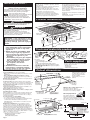
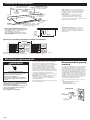
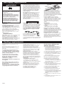
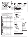
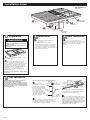
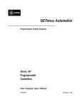
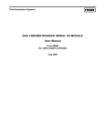
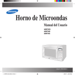
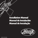
Part No. 8101P350-60/8284676
© 2000 Whirlpool Corporation
Printed in U.S.A.
Benton Harbor, Michigan 49022
Check your Use and Care Guide for a toll-free
number to call, or call the dealer from whom
you purchased this appliance. The dealer is
listed in the Yellow Pages of your phone
directory under “Appliances — Household —
Major — Service and Repair.”
When you call, you will need the cooktop
model number and serial number. Both
numbers can be found on the model/serial
rating plate located on the bottom of the
burner box.
If you need assistance:
If removing the cooktop is necessary for
cleaning or maintenance:
1. Shut off gas supply.
2. Disconnect gas and electrical supplies.
3. Disconnect vent system from unit inside
cabinet.
4. Lift cooktop out of countertop to complete
cleaning or maintenance.
See Use and Care Guide for
troubleshooting list.
After cleaning and maintenance:
1. Reinstall cooktop in cutout.
2. Check that front edge of cooktop is parallel
to front edge of countertop.
3. Connect gas and electrical supplies.
4. Connect vent system.
Check that circuit breaker is not tripped or
the house fuse blown.
Check that the power supply cord is
plugged into the wall receptacle.
Check that the gas supply valves are
turned to the “ON” position.
If cooktop does not
operate:
Cooktop removal
Installation Instructions
Quick Reference
Table of Contents:
Pages
1 Before you start
1 Cutout dimensions
1 Clearance dimensions
2 Product dimensions
2 Tools and materials needed
2 Parts supplied
2 Electrical requirements
3 Gas supply requirements
3
5
4 Venting requirements
6 Installation steps
7 Gas conversions
Back cover Cooktop removal
Need assistance?
30" GAS
Downdraft Cooktop
Modules selected at time of purchase.
Check your Use and Care Guide for a toll-free number to call, or
call the dealer from whom you purchased the cooktop when you:
Have questions about the cooktop installation or operation.
Need to obtain the name and number of an authorized service
company.
The dealer is listed in the Yellow Pages of your phone directory
under “Appliances — Household — Major — Service and Repair.”
When you call, you will need:
The cooktop model number.
The cooktop serial number.
Both numbers are listed on the model/serial rating plate, located
on the bottom of the right side of the downdraft plenum.
Write both numbers down now before installing cooktop.
Model #
IMPORTANT:
Read and save these instructions.
Part No. 8101P350-60/
8284676
Serial #
IMPORTANT:
Installer: Leave Installation Instructions with the homeowner.
Homeowner: Keep Installation Instructions for future reference.
Save Installation Instructions for local electrical inspector's use.
Before you start...
Your safety and the safety of
others are very important.
We have provided many important safety
message in this manual and on your appliance.
Always read and obey all safety messages.
This is the safety alert symbol.
This symbol alerts you to potential hazards
that can kill or hurt you and others.
All safety messages will be preceded by the
safety alert symbol and the word “DANGER” or
“WARNING”. These words mean:
DANGER
WARNING: To reduce the risk of fire,
electric shock, or injury to persons, observe
the following:
Installation work and electrical wiring must
be done by qualified person(s) in
accordance with all applicable codes and
standards, including fire-rated construction.
Sufficient air is needed for proper
combustion and exhausting of gases
through the flue (chimney) of fuel burning
equipment to prevent back drafting. Follow
the heating equipment manufacturer’s
guideline and safety standards such as
those published by the American Society
for Heating, Refrigeration and Air
Conditioning Engineers (ASHRAE), and the
local code authorities.
When cutting or drilling into wall or ceiling,
do not damage electrical wiring and other
hidden utilities.
Ducted fans must always be vented to the
outdoors.
WARNING: To reduce the risk of fire, use
only metal ductwork.
Product dimensions
29-7/8" (75.9 cm)
width
You can be killed or seriously injured if you
don’t immediately follow instructions.
21-1/2" (54.6 cm)
depth
WARNING
You can be killed or seriously injured if you
don’t follow instructions.
All safety messages will tell you what the
potential hazard is, tell you how to reduce the
chance of injury, and tell you what can happen if
the instructions are not followed.
pressure
regulator
Blower can be
swiveled 90°.
wiring box
cover
WARNING: If the information in this
manual is not followed exactly, a fire
or explosion may result causing
property damage, personal injury or
death.
— Do not store or use gasoline or
other flammable vapors and liquids
in the vicinity of this or any other
appliance.
— WHAT TO DO IF YOU SMELL GAS
• Do not try to light any appliance.
• Do not touch any electrical switch.
• Do not use any phone in your
building.
• Immediately call your gas supplier
from a neighbor’s phone. Follow
the gas supplier’s instructions.
• If you cannot reach your
gas supplier, call the fire
department.
— Installation and service must be
performed by a qualified installer,
service agency or the gas supplier.
Important: Observe all governing codes and
ordinances.
Proper installation is your responsibility.
• Make sure you have everything necessary for correct
installation.
• Have a qualified technician install this cooktop.
• Comply with the installation clearances specified on
the model/serial rating plate.
Model/serial rating plate is located on the right side of
the downdraft plenum.
Cooktop location should be away from strong draft
areas, such as windows, doors and strong heating vents
or fans. Locate cooktop for convenient use in kitchen.
Grounded electrical outlet is required. See “Electrical
requirements,” Page 2.
Proper gas supply connection must be available. See
“Gas supply requirements,” Page 3.
Vent system must terminate outdoors.
All openings in the wall or floor where cooktop is to be
installed must be sealed.
When installing a cooktop under existing cabinets and
the installation does not meet the minimum cabinet
clearances, install a range hood above the cooktop to
avoid burn hazards.
It is the customer’s responsibility:
• To contact a qualified electrical installer.
• To assure that electrical installation adequate and in
conformance with National Electrical Code,
ANSI/NFPA 70 — latest edition* and all local codes
and ordinances.
Mobile home installation: The installation of this
cooktop must conform to the Manufactured Home
Construction and Safety Standards, Title 24 CFR, Part
3280 (formerly the Federal Standard for Mobile Home
Construction and Safety; Title 24 HUD part 280); or
when such standard is not applicable, the Standard for
Manufactured Home Installations (Manufactured Home
Sites, Communities and Setups), ANSI A225.1 — latest
edition*, or with local codes.
Copies of the standards listed may be obtained from:
* National Fire Protection Association
One Batterymarch Park
Quincy, Massachusetts 02269
Page 1
grease
container
3-5/16"
(8.4 cm)
burner box
depth
15-5/8"
(39.7 cm)
blower
housing
depth
11-7/8"
(30.2 cm)
14"
(35.6 cm)
Tools and materials needed:
duct
tape
caulking
gun with
weatherproof
caulking
pliers
metal
snips
gloves
safety glasses
Drill
pipe
Phillips
wrench
screwdriver
Not shown:
• gas line shutoff valve
• L.P. gas-resistant pipe-joint compound
• AGA4
or CSA design-certified flexible metal connector
(4-5 feet) (1.2-1.5 m) or rigid gas supply line as needed
• flare union adapter for connection to pressure regulator
(1/2" NPT x 1/2" or 3/4" I.D.)
• wall or roof cap
• metal vent
• 2 sheet metal screws to attach transition vent to venting adapter
tape measure
Parts supplied:
Remove parts from packages. Check that
all parts were included.
• literature pack
• 4 orifice hoods
• exhaust flow rate tester card
Cutout dimensions
28-7/8" (73.3 cm)
cutout width
20-15/16"
(53.2 cm)
cutout depth
15/16" (2.4 cm)
minimum
distance to
backsplash or
vertical wall
Cabinet drawers under the
cooktop will need to be
removed and the drawer
fronts installed
permanently on front of
cabinet.
1-7/8" (4.8 cm)
minimum space
to front edge of
countertop
Minimum base cabinet dimensions —
30" (76.2 cm) base cabinet.
24" (61.0 cm) base cabinet depth
25" (63.5 cm) countertop depth
Select required vent
cutout (see page 4
for exhaust vent
cutout location).
Countertop must be
supported within
3" (7.6 cm) of cutout.
Cutout preparation:
Decorative laminate —
Chamfer all exposed
edges to prevent chipping laminate.
Cut radius corners and file to insure
smooth edges and to prevent cracking.
11" (27.9 cm)
16" (40.6 cm)
side wall
4" (10.2 cm)
4" (10.2 cm)
rear
wall
cabinet bottom
14" (35.6 cm)
Install gas line within shaded
area of cabinet.
16" (40.6 cm)
Install
grounded
electrical
outlet
within
shaded area
of rear wall.
cabinet
bottom
11" (27.9 cm)
28-7/8" (73.3 cm)
Clearance dimensions
Installation location should
provide sufficient room for:
• Removing grease containers.
• Accessing gas regulator.
30" (76.2 cm) minimum when
higher than 18" (45.7 cm)
See Note**
for minimum
clearances.
13" (33 cm)
maximum upper
cabinet depth
18" (45.7 cm)
minimum clearance
upper cabinet
to countertop
2"
(5.1 cm)
0" (0 cm)
Do Not seal
cooktop to
countertop.
Side clearance — 2" (5.1 cm) minimum
clearance is required. 6" (15.2 cm) clearance
between side of cooktop and side wall is
recommended for maximum ventilation
performance.
Rear clearance — The rear edge of the
cooktop may be installed flush with
countertop backsplash. 15/16" (2.4 cm)
clearance between rear edge of appliance and
rear wall is recommended.
Minimum distance to nearest
combustible vertical surface extending
18" (45.7 cm) above cooktop
Motor/blower clearance — 2" (5.1 cm)
clearance is required between motor and
cabinet for proper cooling. 6" (15.2 cm)
clearance is recommended for maximum
performance.
** Note: 30" (76.2 cm) minimum when bottom of wood
or metal cabinet is protected by not less than 1/4"
flame retardant millboard covered with not less than
No. 28 MSG sheet steel, 0.015" stainless steel,
0.024" aluminum or 0.020" copper.
36" (91.4 cm) minimum clearance between the top
of the cooking platform and bottom of unprotected
wood or sheet metal.
2"
(5.1 cm)
min.
motor
blower
clearance
25-7/8"
(65.7 cm)
Spacing for multiple downdraft cooktop installations:
18" (45.7 cm)
minimum
5-3/8"
(13.7 cm)
minimum
between
cutouts
4-3/8"
(11.1 cm)
minimum
between
cooktops
Minimum spacing shown is required for
satisfactory performance when installing the
downdraft cooktop in combination with one
or more downdraft cooktops.
Electrical requirements
WARNING
Electrical Shock Hazard
Plug into a grounded 3-prong outlet.
Do not remove ground prong.
Do not use an adapter.
Failure to follow these instructions
can result in death, fire, or electrical
shock.
If codes permit and a separate ground
wire is used, it is recommended that a
qualified electrician determine that the
ground path is adequate.
Check with a qualified electrician if you
are not sure whether the cooktop is
properly grounded.
Do not ground to a gas pipe.
A 120-volt, 60-Hz, AC-only, 15- or 20-ampere,
fused electrical supply is required. A timedelay fuse or circuit breaker is recommended.
It is recommended that a separate circuit
serving only this appliance be provided.
Electronic ignition systems operate within
wide voltage limits, but proper ground and
polarity are necessary. In addition to checking
that the outlet provides 120-volt power and is
correctly grounded, the outlet must be
checked by a qualified electrician to see if it is
wired with correct polarity.
Important: This cooktop is equipped with an
electronic ignition system that will not
operate if plugged into an outlet that is not
properly polarized.
The wiring diagram is located on the inside of
the terminal box cover.
Recommended ground
method
For your personal safety, this cooktop must be
grounded. This appliance is equipped with a
3-prong ground plug. To minimize possible
shock hazard, the cord must be plugged into a
mating 3-prong ground-type outlet, grounded
in accordance with National Electrical Code
ANSI/NFPA 70 — latest edition* and all local
codes and ordinances. If a mating outlet is not
available, it is the personal responsibility and
obligation of the customer to have a properly
polarized and grounded, 3-prong outlet
installed by a qualified electrician.
Copies of the standards listed above may be obtained
from:
* National Fire Protection Association
One Batterymarch Park
Quincy, Massachusetts 02269
3-prong polarized
ground-type outlet
3-prong
ground plug
ground
prong
power
supply cord
Page 2
Gas supply requirements
WARNING
Explosion Hazard
Use a new AGA or CSA approved gas
supply line.
Install a shut-off valve.
Securely tighten all gas connections.
If connected to LP, have a qualified
person make sure gas pressure does
not exceed 14" water column.
Examples of a qualified person
include licensed heating personnel,
authorized gas company personnel,
and authorized service personnel.
Failure to do so can result in death,
explosion, or fire.
Observe all governing codes and
ordinances.
Important: Cooktop must be connected
to a regulated gas supply.
This installation must conform with all local
codes and ordinances. In the absence of local
codes, installation must conform with
American National Standard, National Fuel
Gas Code ANSI Z223.1 — latest edition* and
all local codes and ordinances.
Copies of the standards listed above may be obtained
from:
* CSA International
8501 East Pleasant Valley Road
Cleveland, Ohio 44131-5575
Input ratings shown on the model/serial rating
plate are for elevations up to 2,000 feet
(610 m). For elevations above 2,000 feet
(610 m), ratings are reduced at a rate of 4% for
each 1,000 feet (305 m) above sea level.
Type of gas: This downdraft cooktop is factory
set for use with Natural gas. It is design-
certified by CSA International for Natural or
L.P. gas usage with appropriate conversion.
(See “Gas conversion” instructions, Page 7).
The model/serial rating plate (located on the
right side of the downdraft plenum) lists the
type of gas that can be used. If the type of gas
listed does not agree with the type of gas
available, check with the local gas supplier.
Conversion must be done by a qualified
service technician.
Gas supply line: With Natural gas, provide a
gas supply line of 3/4" rigid pipe to the
downdraft cooktop location. With L.P. gas,
piping or tubing can be 1/2" minimum. A
smaller size pipe on long runs may result in
insufficient gas supply. Usually, L.P. gas
suppliers determine the size and materials
used on the system.
Pipe-joint compounds made for use with L.P.
gas must be used.
Flexible metal appliance connector: If local
codes permit, a new AGA or CSA designcertified, 4-5 foot long, 1/2" or 3/4" I.D., flexible
metal appliance connector is recommended
for connecting the cooktop to the gas supply
line. A 1/2" male pipe thread is needed for
connection to pressure regulator female pipe
threads. Do Not kink or damage the flexible
metal tubing when moving the downdraft
cooktop.
If rigid pipe is used as a gas supply
line, a combination of pipe fittings
must be used to obtain an in-line
connection to the downdraft
cooktop. All strains must be removed from the
supply and fuel lines so cooktop will be level
and in line.
shutoff valve
“open” position
to downdraft
cooktop
to gas
supply
Shutoff valve: The supply line must be
equipped with an approved manual shutoff
valve. This valve should be located in the
same room as the downdraft cooktop and
should be in a location that allows ease of
opening and closing. The valve is for turning
on or shutting off gas to the appliance. Do Not
block access to shutoff valve.
Pressure regulator: The gas pressure
regulator supplied with this downdraft
cooktop must be used. The regulator must be
checked at a minimum 1-inch water column
above the set pressure. The inlet pressure to
the regulator should be as follows for
operation and for checking the regulator
setting:
NATURAL GAS:
Minimum pressure: 6 inches WC
Maximum pressure: 14 inches WC
L.P. GAS:
Minimum pressure: 11 inches WC
Maximum pressure: 14 inches WC
Line pressure testing above 1/2 psi gauge
(14" WC) — The downdraft cooktop and its
individual shutoff valve must be disconnected
from the gas supply piping system during any
pressure testing of that system at test
pressures greater than 1/2 psi (3.5 kPa).
Line pressure testing at 1/2 psi gauge
(14" WC) or lower — The downdraft cooktop
must be isolated from the gas supply piping
system by closing its individual manual
shutoff valve during any pressure testing of
that system at test pressures equal to or less
than 1/2 psi (3.5 kPa).
Venting requirements
Venting system must terminate to the
outside.
Do Not terminate the vent system in an
attic or other enclosed space.
Do Not use 4-inch (10 cm) laundry-type
wall caps.
Use metal vent only. Exception: See
“optional venting under a concete slab”,
in “Venting methods” on Page 4. Rigid
metal vent is recommended. Do not use
plastic or metal foil vent.
To reduce risk of fire and to properly
exhaust air, be sure to vent air outside.
Do Not vent exhaust air into spaces
within walls or ceilings or into attics,
crawl spaces or garages.
Vent materials needed for installation are
not supplied.
Before making cutouts, make sure there is
proper clearance within the wall or floor for
the exhaust vent.
Do Not cut a joist or stud unless absolutely
necessary. If a joist or stud must be cut, then
a supporting frame must be constructed.
Page 3
Determine which venting method to use. See
“Venting methods,” Page 4.
Next, determine the equivalent vent length
using the chart on page 4. This cooktop is
equipped with a dual range blower. The
equivalent vent length (not actual) determines
whether blower is set at the “Low” or “High”
range. The blower is set at the “Low” range
setting at the factory.
The blower housing must be rotated or
swiveled to the proper angle needed for your
installation. The blower can be swiveled 90°.
The blower may be rotated horizontally or
vertically. Reach through the ventilation
chamber to loosen, but Do Not remove, the
nuts around the blower inlet to adjust blower.
This downdraft cooktop is rated at 60 feet of
straight vent.
• If vent length is 10 feet or less,
5" diameter round vent MUST be used.
• If vent length is more than 10 feet, use
6" diameter round or 3-1/4" x 10" rectangular
vent.
Thermal breaks: In areas of extreme cold
weather, it may be necessary to provide a
short length of nonmetallic vent as close to
the wall as possible to prevent thermal
conduction along the metal vent.
For altitudes above 4,500 ft, reduce
recommended vent run by 20%.
For the most efficient and
quietest operation:
Use 26-gauge minimum galvanized or
25-gauge minimum aluminum metal vent.
Poor-quality pipe fittings can reduce air
flow. (Note: Local codes may require a
heavier-gauge material.) Flexible metal
vent is not recommended.
Do Not exhaust more than one downdraft
cooktop into a single vent system.
The length of vent and number of elbows
should be kept to a minimum to provide
efficient performance.
The size of the vent should be uniform.
Use no more than three 90° elbows.
Do Not install two elbows together.
Make sure there is a minimum of 18"
of straight vent between the elbows if
more than one elbow is used. (Elbows too
close together cause excess turbulence
that reduces airflow.)
Do Not use a 5" elbow in a 6" or
3-1/4" x 10" system. Instead, use a 5" to 6"
transition followed by a 6" elbow, or a 5"
to 3-1/4" x 10" elbow transition.
Do Not reduce back to 5" system after
using 6" or 3-1/4" x 10" fittings.
Avoid forming handmade crimps.
Handmade crimps may restrict airflow.
Use the recommended vent caps for
proper performance. If an alternate wall or
roof cap is used, be certain cap size is not
reduced and that it has a backdraft
damper.
Use duct tape to seal all joints in the vent
system.
Use caulking to seal exterior wall or roof
opening around the cap.
Venting methods
20-15/16"
(53.2 cm)
28-7/8"
(73.3 cm)
13"
(33 cm)
9-3/8"
(23.8 cm)
opening
for venting
through floor
inside wall
cabinet
7-9/16"
(19.2 cm)
3-1/4" x 10"
transition
elbow
a
outside wall
cabinet
peninsula
or island
peninsula
transition
elbow
3-1/4" x 10"
inside wall to roof
or overhang
opening for venting
through rear wall
directly
outside
between floor joists
cabinet toe space
to outside
6" round metal vent
wall cap
SBCCI
The cooktop may be vented through the
rear wall or floor. Common venting
methods and the types of materials
needed are shown.
Make sure there is proper clearance within
the wall or floor for exhaust vent before
making cutouts.
6" round metal vent
16" (40.6 cm)
maximum
6" round PVC coupling
a
12" minimum
(30.5 cm)
5" to 6" round metal transition
6" round PVC
sewer pipe
concrete slab
6" round PVC
coupling
6" diameter
90° PVC
sewer pipe
6" round PVC sewer
pipe
Tightly pack gravel
or sand completely
around pipe.
6" diameter
90° PVC
sewer pipe
30’ (9.1 m)
maximum
optional vent arrangement under concrete slab
Determine range blower setting.
This cooktop is equipped with a dual range blower. It is factory set at
“Low” range to be used for equivalent vent length runs of 30 feet
(9.1m) or shorter. If the equivalent vent length exceeds 30 feet (9.1m),
the blower must be shifted to “High” range. Do Not shift to “High”
range for runs shorter than 30 feet (9.1m). Using the “High” range on
shorter runs will cause excessive noise and conditioned air loss, and
will affect the flame pattern of gas burners.
List the number of each piece and length of straight vent you will use.
Multiply the equivalent length by the number of pieces. Add the totals
to get the total equivalent length of your system.
Vent
Piece
Equivalent
Length
straight vent per lineal ft.
3-1/4" x 10"
6" round
6" flexible
No. of
Pieces/
Length
Total
Equivalent
Length
1 ft. (30.5 cm)
1 ft. (30.5 cm)
2 ft. (61 cm)
elbow
6" round 45° elbow
2 .5 ft. (76 cm)
6" round 90° elbow
5 ft. (152 cm)
3-1/4" x 10" flat elbow
12 ft. (366 cm)
3-1/4" x 10" 90° elbow
5 ft. (152 cm)
transition to round
5" to 6"
1 ft. (30.5 cm)
Vent system equivalent length 30 feet
or less — blower should be set at
“Low” range.
Example:
blower at
Low range
2 ft.
(61 cm)
5" to 6" transition
4 ft. (122 cm)
6", 90° elbows
6", wall
cap
6 ft. (183 cm)
90° elbows (2)
12 feet (366 cm) straight
5" to 6" transition
Wall cap
= 10 ft.
= 12 ft.
= 1 ft.
= 0 ft.
(305 cm)
(366cm)
(30.5 cm)
(0cm)
Equivalent length of 6" round system = 23 ft.
(701.5 cm)
(In this example, blower can be left in “Low” range as set at factory.)
Vent system equivalent length greater
than 30 feet — blower should be set at
“High” range.
Example:
air flow
3-1/4" x 10" to 6" 90° elbow
air flow
3-1/4" x 10" to 6"
9 ft. (274 cm)
4.5 ft. (137 cm)
restricter
ring
5" to 6" transition
2 ft.
(61 cm)
transition to flat
5" to 3-1/4" x 10" 90° elbow
6" to 3-1/4" x 10" 90° elbow
Shifting blower
to “High” range
4 ft. (122 cm)
6 ft. (183 cm)
air flow this direction
not recommended
air flow
6", 90° elbows
6 ft. (183 cm)
5 ft. (152 cm)
4 ft.
(122 cm)
air flow
6" to 3-1/4" x 10"
10 ft. (305 cm)
1 ft. (30.5 cm)
6" to 3-1/4" x 10"
transition
air flow
wall cap*
3-1/4" x 10"
0 ft. (0 cm)
5" or 6" round
0 ft. (0 cm)
10" x 10"
0 ft. (0 cm)
roof cap*
thermal break
5" or 6" round
2 ft. (61 cm)
Total equivalent vent system length
* Length for required wall/roof cap has already been incorporated
into rating for maximum vent system length. A suitable wall/roof
cap must be used.
Page 4
blower
To shift blower to
“High” range:
1. Turn blower off.
2. Remove the air grille and
filter from blower housing.
3. Snap the spring-loaded
restricter ring out of the
blower inlet.
4. Reinstall the filter and air
grille.
3-1/4" x 10" wall cap
90° elbows (3)
5" to 6" transition
6" to 3-1/4" x 10" transition
Wall cap
16 feet (488 cm) 6" straight
10 feet (305 cm) 3-1/4" x 10" straight
= 15 ft. (
= 1 ft. (
= 1 ft. (
= 0 ft. (
= 16 ft. (
= 10 ft. (
457.2 cm)
30.5 cm)
30.5 cm)
0 cm)
488 cm)
305 cm)
Equivalent length of 6" round system = 43 ft. (1311.2 cm)
(In this example, blower MUST be shifted to “High” range.)
Note: Flexible metal vent is Not recommended.
If it is used, calculate each foot of flexible duct as two
feet of straight metal vent. Flexible metal elbows count
twice as much as standard elbows.
Installation steps
Note: Cooktop shown
with optional grill
accessory.
E
B
Check each burner
for proper flame
Align cooktop
in cutout
D
Gas supply
connection
A
Blower range
setting
C
Vent system
connection
A Preparation
WARNING
Excessive Weight Hazard
Use two or more people to move and
install cooktop.
Failure to do so can result in back or
other injury.
C Vent connection
B Installation
3.
Insert downdraft cooktop into
cutout. Check that:
cooktop is centered in cutout.
front edge of downdraft cooktop is at
least 1-1/2" (3.8 cm) from front edge of
countertop and parallel to countertop.
side edge of cooktop is at least 2 inches
(5.1 cm) from side wall.
4.
Connect vent system. See
“Venting requirements,” pages 3-4. Use
duct tape to seal all joints. Vent must end
with a wall or roof cap outside the
building.
1.
2.
Remove the downdraft cooktop
from packaging.
Check equivalent vent length to
determine if blower should be set at
“Low” or “High” range (see chart on page
4 to determine equivalent vent system
length). If vent system length is greater
than 30 feet (9.1m), shift the blower range
setting from “Low” to “High” (see
instructions on page 4 for shifting the
blower range).
If blower must be shifted to “High” range,
do it now.
D Gas connection
IMPORTANT: All connections must be
wrench-tightened. Do Not make
connections to the gas regulator too tight.
Making the connection too tight may crack
the regulator and cause a gas leak. Do Not
allow the regulator to turn on the pipe when
tightening fittings.
All connections must be wrench-tightened.
shutoff valve
“open” position
burner box
5.
Assemble
the flexible connector
1/2"
from the gas supply pipe nipple
to the pressure regulator
in order: manual shutoff
valve, 1/2" nipple,
flexible
connector
1/2" adapter, flexible
connector, 1/2" adapter,
1/2" nipple and pressure
regulator. Or install rigid
1/2"
piping as required.
nipple
6.
pressure
regulator
to gas
supply
1/2"
adapters
7.
manual
shutoff
valve
8.
Use pipe-joint compound made for
use with L.P. gas to seal all pipe thread gas
connections. If flexible connectors are used, be
certain connectors are not kinked.
Page 5
to downdraft
cooktop
Open the manual shutoff valve in
the gas supply line. Wait a few minutes for
the gas to move through the line.
Use a brush and liquid detergent to
test all gas connections. Bubbles around the
connections will indicate a leak. If a leak
appears, shut off gas valve controls and
adjust connections. Then check connections
again. NEVER TEST FOR GAS LEAKS WITH
A MATCH OR OTHER FLAME. Clean all
detergent from the cooktop.
12.
E Check operation
Push in and turn each surface
burner control knob to “LITE” position and
then to “LO” position. The low flame should
be a minimum, steady blue flame.
Do Not use a metal blade to pry off control
knob; this could damage the product. If the
control knob cannot be easily removed, tuck
a cloth under the knob and pull upward on
cloth with steady, even pressure to remove
knob.
9.
Plug the
power supply cord
into the grounded
outlet.
to
op
en
to
clo
se
air
opening
To adjust
grill burner
air shutter
air
shutter
counterclockwise
to increase flame
flow tester
air intake
clockwise to
reduce flame
flow tester
valve stem
edge of line
on flow tester
front of cooktop
10.
Check for proper venting:
• Check that the air filter is in place.
• Align the dotted line labeled for “cooktop
models” on the flow tester with the edge
of the intake on the left side of the cooktop
near the center.
• Turn on the downdraft system:
If the card is pulled into the air intake,
your downdraft is working properly.
If the card is not pulled into the system,
see “Venting requirements,” Pages 3-4,
and check vent installation for possible
causes.
If the low flame needs adjusting –
• Remove the control knob and turn the
adjustment screw in the center of the valve
stem. Do Not turn screw more than 1/2
revolution in either direction.
• Replace the control knob. Check the
adjustment by turning the control knob from
“HI” to “LO” several times. The burner is
properly adjusted when the low flame
remains steady and the burner does not go
out.
• Turn control knob to “OFF” position.
• Repeat if necessary for other surface burner.
Electronic ignitions system
Cooktop burners use electronic ignitors in
place of standing pilots. When the cooktop
control knob is turned to the “LITE”
position, the system creates a spark to light
the burner. This sparking continues until the
control knob is turned to the desired setting.
Check operation of right-side surface
burners module
OFF
LO
11.
MED
Push down and turn
each surface burner
control knob to
“LITE” position. The
HI
LITE
flame should light within
4 seconds. Turn the control
knob to “HI” position after
burner lights. Do Not leave the knob in the
“LITE” position after burner lights.
Check each surface burner for
proper flame at “HI” setting. The
small inner cone should have a
very distinct, blue flame that is
1/4" (0.6 cm) to 1/2" long (1.3 cm).
The outer cone is not as distinct as
the inner cone. Turn surface
burner control knobs to “OFF” position.
screw
air
shutter
air
opening
to
close
to
open
To adjust
surface
burner air
shutter
surface burner
air shutter
If surface burner flames need adjusting –
• Remove burner grate and burner pan.
• Turn control knob to “HI” position.
• Loosen the air shutter screw. Adjust the air
shutter to the widest opening that will not
cause the flame to lift or blow off the burner.
• After adjusting air shutter, tighten air shutter
screw.
• Turn control knob to “OFF” position.
• Replace burner grate and burner pan.
• Repeat if necessary for other surface burner.
Page 6
Check operation of left-side surface
burners or optional grill module
13.
Use module instructions to install
left-side surface burner or optional grill
module.
Surface burners module: Push in and turn
right surface burner control knob to “LITE”
position. The flame should light within
4 seconds. Turn the control knob to “HI”
position after burner lights. Do Not leave the
knob in the “LITE” position after burner
lights.
Check surface burner for proper
flame. The small inner cone will be
similar to the right-side module
surface burner flames, but will be
shorter and softer. The outer cone is
not as distinct as the inner cone.
Turn surface burner control knob to
“OFF” position.
Repeat for left surface burner control knob.
Grill module: Remove grill grates and burner
pan. Push in and turn right control knob to
“LITE” position. The flame should light within
4 seconds. Turn the control knob to “HI”
position after burner lights. Do Not leave the
knob in the “LITE” position after burner
lights.
Check the grill burner for proper flame. The
small inner cone will be similar to the rightside surface burner flames, but will be shorter
and softer. The outer cone is not as distinct as
the inner cone. Turn grill burner control knob
to “OFF” position.
Repeat for left grill burner control knob.
grill burner
air shutter
If burner flames need adjusting –
• Remove surface burner grates and burner
pan.
• Push in and turn control knob to “LITE”
position and then to “HI” position.
• The right air shutter controls the front half
of the burner; the left air shutter controls
the rear half. Insert a screwdriver blade in
the air shutter slot that needs adjusting
and lightly twist the screwdriver to slide
air shutter backward or forward to adjust
the flame. Adjust the burner air shutter to
the widest opening that will not cause the
flame to lift or blow off the burner.
• Turn control knob to “OFF” position.
• Repeat if necessary for other burner
control knob.
14.
Push in and turn each control
knob to “LITE” position and then to “LO”
position. The low flame should be a
minimum, steady blue flame.
If low flame needs adjusting –
• Remove the control knob and turn the
adjustment screw in the center of the
valve stem. Do Not turn screw more than
1/2 revolution in either direction.
• Replace the control knob. Check the
adjustment by turning the control knob
from “HI” to “LO” several times. The
burner is properly adjusted when the low
flame remains steady and the burner does
not go out.
• Turn control knob to “OFF” position.
• Repeat if necessary for other burner
control knob.
• Replace surface burner grates and burner
pan or grill grates and burner pan.
You have just finished installing
your new downdraft cooktop.
To get the most efficient use
from your new cooktop,
read your Use & Care Guide.
Keep Installation Instructions
and Guide close to cooktop
for easy reference.
Gas conversions
right rear
burner
Orifice hoods:
Natural — Brass, drill size #53
(orifice dia. 0.0595")
L.P. — Blue, drill size #63
(orifice dia. 0.037")
right front
burner
left rear
burner
pressure regulator
Orifice hoods:
Natural — Green, drill size #55
(orifice dia. 0.052")
L.P. — Zinc, drill size #66
(orifice dia. 0.033")
left front
burner
Gas conversions (from Natural gas to L.P.
gas; or from L.P. gas to Natural gas) must be
done by a qualified installer.
WARNING
Fire Hazard
Shut off main gas supply line valve.
Make all conversions before turning gas
supply valve back on.
Failure to follow these instructions can
result in explosion, fire or other personal
injury.
L.P. gas conversion
Natural gas conversion
1.
1.
Complete installation sections A-C
(page 5) before converting cooktop to L.P.
gas. Check that main gas supply line has
been shut off and the power supply cord is
disconnected.
Pull up
on disc.
L.P.
cap and
pin
Squeeze
to remove
pin from
cap.
natural
cap and
pin
Shut off main gas supply line and
disconnect the power supply cord.
L.P. position
Squeeze
and press
down.
natural gas position
Press
down
on disc.
pressure
regulator
natural gas position
DO NOT REMOVE THE PRESSURE
REGULATOR.
pressure
regulator
L.P. position
DO NOT REMOVE THE PRESSURE
REGULATOR.
2.
Turn cap on top of pressure regulator
counterclockwise with a wrench to remove
cap. Squeeze edges of pin with your fingers
and pull upward to remove pin from cap. Turn
pin over so disk end is up. Press down on disk
to snap pin in place on cap. Reinstall cap on
pressure regulator.
2.
Turn cap on top of pressure regulator
counterclockwise with a wrench to remove
cap. Pull upward on edges of disk with your
fingers to remove pin from cap. Turn pin over
so disk end is down. Squeeze pin and snap it
into place on cap. Reinstall cap on pressure
regulator.
front of
unit
front of
unit
1/2" open-end
wrench
clockwise
to install
1/2" open-end
wrench
clockwise
to install
counterclockwise
to remove
orifice hood
3.
Remove Natural gas orifice hoods by
turning hoods counterclockwise with 1/2"
open-end wrench. Locate color-coded L.P. gas
orifice hoods and sticker in plastic parts bag
attached to right side of plenum.
• Zinc-colored orifice hoods, drill size #66
(orifice dia. 0.033"): Install on LEFT rear and
front burners.
• Blue-colored orifice hoods, drill size #63
(orifice dia. 0.037"): Install on RIGHT rear and
front burners.
Place Natural gas hoods in plastic parts bag
for future use. Reattach bag to plenum.
4.
Page 7
Complete installation Sections D
through E. L.P. gas flames have slightly
yellow tips in addition to the other proper
characteristics.
counterclockwise
to remove
orifice hood
3.
Remove surface burner and grille
modules from cooktop. Remove L.P. gas
orifice hoods by turning hoods
counterclockwise with 1/2" open-end wrench.
Locate color-coded Natural gas orifice hoods
in plastic parts bag attached to bottom of
cooktop.
• Green-colored orifice hoods, drill size #55
(orifice dia. 0.052"): Install on LEFT rear and
front burners.
• Brass-colored orifice hoods, drill size #53
(orifice dia. 0.0595"): Install on RIGHT rear
and front burners.
Place L.P. gas hoods and sticker in plastic
parts bag for future use. Reattach bag to
plenum.
4.
After all the burners have been
converted to Natural gas, plug the power
supply cord into a grounded outlet. Adjust the
air shutters and flame following the
instructions in Section E. Natural gas burner
flames do not have yellow tips.
Part No. 8101P350-60/8284676
© 2000 Whirlpool Corporation
Benton Harbor, Michigan 49022
Printed in U.S.A.
Check your Use and Care Guide for a toll-free
number to call, or call the dealer from whom
you purchased this appliance. The dealer is
listed in the Yellow Pages of your phone
directory under “Appliances — Household —
Major — Service and Repair.”
When you call, you will need the cooktop
model number and serial number. Both
numbers can be found on the model/serial
rating plate located on the bottom of the
burner box.
If you need assistance:
If removing the cooktop is necessary for
cleaning or maintenance:
1. Shut off gas supply.
2. Disconnect gas and electrical supplies.
3. Disconnect vent system from unit inside
cabinet.
4. Lift cooktop out of countertop to complete
cleaning or maintenance.
See Use and Care Guide for
troubleshooting list.
After cleaning and maintenance:
1. Reinstall cooktop in cutout.
2. Check that front edge of cooktop is parallel
to front edge of countertop.
3. Connect gas and electrical supplies.
4. Connect vent system.
Check that circuit breaker is not tripped or
the house fuse blown.
Check that the power supply cord is
plugged into the wall receptacle.
Check that the gas supply valves are
turned to the “ON” position.
If cooktop does not
operate:
Cooktop removal
Installation Instructions
Quick Reference
Table of Contents:
Pages
1 Before you start
1 Cutout dimensions
1 Clearance dimensions
2 Product dimensions
2 Tools and materials needed
2 Parts supplied
2 Electrical requirements
3 Gas supply requirements
3
5
4 Venting requirements
6 Installation steps
7 Gas conversions
Back cover Cooktop removal
Need assistance?
30" GAS
Downdraft Cooktop
Modules selected at time of purchase.
Check your Use and Care Guide for a toll-free number to call, or
call the dealer from whom you purchased the cooktop when you:
Have questions about the cooktop installation or operation.
Need to obtain the name and number of an authorized service
company.
The dealer is listed in the Yellow Pages of your phone directory
under “Appliances — Household — Major — Service and Repair.”
When you call, you will need:
The cooktop model number.
The cooktop serial number.
Both numbers are listed on the model/serial rating plate, located
on the bottom of the right side of the downdraft plenum.
Write both numbers down now before installing cooktop.
Model #
IMPORTANT:
Read and save these instructions.
Part No. 8101P350-60/
8284676
Serial #
IMPORTANT:
Installer: Leave Installation Instructions with the homeowner.
Homeowner: Keep Installation Instructions for future reference.
Save Installation Instructions for local electrical inspector's use.