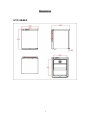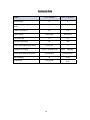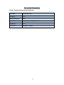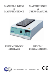
1
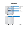
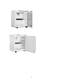
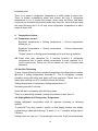
Se
ervice Manual FILE No.HM
MRSM‐005‐‐02 Pharmaacy Refriigerator
HYC--68•HYC
C-68A
HYC-1
118•HYC
C-118A
1
Content Designation .................................................................................................................... 3 Introduction to Features of Product ............................................................................... 4 Product appearance ........................................................................................................ 5 Dimensions .................................................................................................................... 7 product nameplate .......................................................................................................... 8 Technical Data ............................................................................................................. 10 Circuit Diagram ........................................................................................................... 11 Compressor Parameters ............................................................................................... 11 Fan motor Parameters .................................................................................................. 13 Computer Board ........................................................................................................... 14 Operation panel ............................................................................................................ 15 Peripheral Signal of Computer Board .......................................................................... 16 Function Control .......................................................................................................... 17 Display and Key Control ............................................................................................. 17 Trouble Display and Treatment.................................................................................... 24 Details of Main Replacement Parts.............................................................................. 25 Common Trouble Analysis and Repair Measures........................................................ 27 Reply of Common Problems ........................................................................................ 28 Structural Principle Sketch of Refrigeration System ................................................... 29 Important components to install and remove ............................................................... 30 Gas collection and charge ............................................................错误!未定义书签。 Testing Date ................................................................................................................. 37 2
Designation
Regulations for type naming: HYC
XXX
X
Design No. is expressed with pinyin
character sequence Rated volume value is shown with L
Pharmacy Refrigerator Note: rated volume can be the gross volume or effective volume; the manufacturer can decide it by him according to the actual situation. The effective volume value must be marked on the nameplate whether effective volume or gross volume is marked in the product name. HYC-68A is the replacement of the sight glass doors on the basis of HYC-68.
3
Introduction to Features of Product
1.
Medical pharmaceutical refrigerator: Temperature can be between 2℃
and 8℃;
2.
Micro-computer control and digital display for refrigerator temperature;
3.
Automatic defrosting;
4.
Visible acoustic-optical alarm for over-temperature alarm, door-opening
alarm and sensor trouble alarm;
5.
Air-cooled system with reliable operation;
4
Produ
uct appea
arance
Con
ntrol panel Light Fan
n Sheelf Door handle Door lock Foo
oting 5
6
Dimensions
HYC-68/68A
7
product nameplate
For example: HYC‐68 For example: HYC‐68A 8
For example: HYC‐118 For example: HYC‐118A 9
Technical Data
Model
HYC-68/68A
HYC-118/118A
Weather type
N
N
Protection type against electric
shock
I
I
68
118
Rated voltage
220V/50Hz
220V/50Hz
Fan power (W)
1.3
1.3
Total input power(W)
84
160
0.57/0.93
1.1
Effective volume (L)
Power consumption (kW·h/24h)
Refrigerant R134a(g)
Outline dimension (w*d*h)(mm)
R134A 71g/R600a 22g
500*490*640
597×645×835
38
41/46
HVY57AA
TL5G
Net weight(kg)
Compressor
R134A 90g/85g 10
Circuit Diagram
HYC‐68/68A/118 HYC‐118A 11
Compressor Parameters
(Under Standard Operating Conditions)
Product model
HYC-68/68A
HYC-118/118A
Compressor model
Zanussi HVY57AA
TL5G
Refrigeration capacity (W)
95
Input power(W)
68.4
Rated voltage(V)
220-240
220-240
Rated frequency(Hz)
50
50
Current(A)
0.38
Cooling mode
Natural cooling
Oil infill (cc)
200 (mineral oil)
12
Natural cooling
Fan motor Parameters
(Under Standard Operating Conditions)
Fan model: AD0912LB‐A71GL Voltage(V): DC 12 Rotate speed(rpm): 2300 线路描述: 红色线为正极,黑色线为负极 Current(A): 0.13 叶片材质: 黑色 ABS 工程塑料 13
Computer Board
1. The computer board consists of display board and main control board for
close cooperation.
2. Basic parameters (for power):AC current
2.1. Rated voltage: 220~240V
2.2. Rated frequency: 50Hz as universal frequency
2.3. Rated power: 350W
2.4. Automatic voltage identification: With
2.5. Automatic frequency identification: With
2.6. The maximum operating load of controller: 500W
3. Safety certification requirements: CE certification, 3C certification
4. Environmental protection: To meet ROHS requirements.
5. Load requirements (for compressor):
Rated voltage: 220~240V
Rated frequency: 50Hz
Rated power: 350W
Rated rotation speed: Constant frequency
Load type: Inductive load
Operation characteristics: Perennial work with frequent startup
With/without speed control: Without control
With/without motor trouble protection: Twice bootstrap period can not be
less than 5 minutes.
6. The computer board has antiriot functions.
7. Interference resistance requirements:
The computer board has interference resistance functions. Electromagnetic
wave transmitted by common electronic appliances such as mobile phone and
play station, etc cannot influence normal operation of computer board.
14
Operation panel
1. Appearance:
(Display panel and display board are shown in following figure.)
2. Key
2.1 Temperature up/down key: To press up/down key for temperature setting.
2.2 Setting key: To set functions and enquire the maximum and minimum
refrigerator temperature.
2.3 Lighting switch key: To press lighting key so that lighting lamp is on. To
press it again so that it is off.
2.4 Alarm key: To set alarm limit, inquiry of upper and lower alarm limits and
trouble cancellation functions;
15
Peripheral Signal of Computer Board
1. System input quantity:
A、 Temperature sensor: With ordinary refrigeration sensor in the refrigerator;
B、 Key signal: Please refer to key definition for details.
C、 Door switch signal: With door switch signal;
Fan is connected when door body is closed and it is disconnected when door
body is opened. Door switch is fitted with normally closed switch. That is, 2
terminals of switch are closed when opening the door body.
D、 Over-zero detection signal:The same to ordinary one;
2.
System output control quantity:
A、 Press control:
temperature.
Constant
frequency
compressor
is
controlled
by
B、 Control of lighting lamp: There is 1 group of LED lighting lamps. There are
3 emitting diodes of DC 12V and 120mA for every group. Lighting lamps
are controlled by lighting lamp switch.
C、 Fan in the refrigerator: There is a DC 12V fan of 1.3W in the refrigerator. It
is controlled by door switch.
D、 Display control: With display control
E、 Buzzer control: With buzzer
16
Function Control
Display and Key Control
1.
Display:
1.1
Refrigerator shall display actual temperature during initial power
supply and after temperature reduces to the minimum value and
before increasing to setting temperature which corresponds to such
temperature gear.
1.2
Current actual temperature is ±2°C of setting temperature for gradual
variation to setting temperature. Display temperature will change to
actual temperature gradually without temperature variation jumping
under normal conditions if current temperature exceeds setting
temperature by 2°C. Variation is ±1°C /min during all temperature
variations;
1.3
Please conform with Clause 3 during setting alternation;
1.4
Displayable scope of display board refrigerator is 50℃ to -45℃.
Adjustable scope is 20℃ to -40℃.
1.5
Please conform to Clause 4 for over-temperature alarm and sensor
trouble alarm.
2.
Color definition of indicator lamp:
(As shown in display effect diagram), display is a 3-bit digital display with 2
indicator lamps above it. It is alarm indicator lamp(ALARM) and it is on during
alarm. The other is output indicator lamp and it is on during press bootstrap.
The lamp flickers when temperature reaches bootstrap point but press has not
been started up due to delay. Please check if alarm or output indicator lamp is
on or not according to actual conditions during power supply of display board.
3.
Initial status:
Operation status for initial power supply is initial status.
Operating temperature of refrigerator: Default setting temperature is 4℃ and
lamp in it is closed. Display control board will display default setting
temperature and flickers by frequency of 1Hz. It will display actual temperature
of refrigerator automatically after 5 seconds. Press will not be started up if
refrigerator temperature is between bootstrap point and shutdown point during
initial power supply. It can not be started up until temperature reaches
17
bootstrap point.
There is no alarm if refrigerator temperature is within scope of alarm limit.
There is instant temperature alarm and buzzer will ring if refrigerator
temperature is out of control limit scope. Alarm lamp will flicker and alarm
sound can be cancelled by pressing alarm key. However, alarm indicator lamp
will keep flickering and it is off only when refrigerator temperature is within
scope of alarm limit.
4.
Temperature control
4.1 Temperature control
Bootstrap temperature = Setting temperature + Control temperature
difference, rd
Shutdown temperature = Setting temperature – Control temperature
difference, rd
“Output” lamp is on during press bootstrap and it is off during shutdown.
4.2 Press shall stop operation for 5 minutes forcefully if refrigerator
temperature fails to reach setting temperature if press operates for 4
hours continuously. Press can not be started up until 5 minutes after
shutdown.
4.3 Hot Gas Defrosting
To stop forced defrosting if accumulated compressor bootstrap period reaches
d2 hours if setting temperature exceeds 0℃. Fan in refrigerator normally
operates during defrosting and press will stop operation. Please start up it
again after meeting one of 2 conditions shown as follows:
Testing temperature of refrigerator Setting temperature+4℃
Defrosting period≥15 minutes;
Press will start up instantly after defrosting ends.
There is no defrosting demand if setting temperature is less than 0℃.
4.4 Setting Method of Refrigerator Temperature
Setting refrigerator temperature shall be adjusted according to following
method:
To press SET key then loosen it quickly so that display window can display
original design value with flickering. To press “+” or “-” to adjust setting value if
it flickers.
Setting value can vary by 1℃ by pressing it every time. It will exit automatically
18
and display refrigerator temperature again (without flickering) if there is no
operation within 10 seconds.
4.5 Setting of Internal Parameters
Several internal parameters can be adjusted by following method to guarantee
normal operation of refrigerator:
To press “regulate” key for more than 10 seconds to display original design
value (rd) with flickering; To press “+” or “-” to adjust setting value. Adjustment
scope is 1℃ to 4℃ because setting value can vary by 1℃ by pressing the key
every time. To press “alarm” key to exit and return to previous layer for rd
display. (To press “alarm” key to return to previous layer by pressing the key
once until return to refrigerator temperature display). To select next parameter
by pressing “+” or “-”. Internal parameters are shown in the 1st attached form.
Regulation method is as above.
19
Form 1:Internal parameter form under control contents
Internal
parameter
Parameter instructions
Scope
Default
value
Instructions
/unit
rd
Adjustment gain is 1 for
setting temperature
difference
1~6
2
℃
r1
Adjustment gain is 1 for
the maximum setting
temperature
LE~20
8
℃
3
r2
Adjustment gain is 1 for
the minimum setting
temperature
-40~HE
0
℃
4
c1
Press delay startup period
during controller operation
0~10
0
min
5
c2
The minimum compressor
shutdown period
0~10
5
min
c3
Long-term operation
period of fast chilled
compressor
1~50
24
hour
do
Adjustment gain is 1 when
controlling operation
period under trouble
5~15
10
min
dF
Adjustment gain is 1 when
controlling shutdown
period under trouble
5~15
10
min
9
d1
Defrosting type (1—hot
gas defrosting; 2—electric
defrosting)
1-2
1
--
10
d2
Detailed defrosting interval
4-16
8
Hour
11
AD
Delay period of
temperature alarm
0~20
15
min
12
CA
Correction of display
temperature
-5~+5
0
℃
No.
1
2
6
7
8
20
4.6 Inquiry of the Maximum and Minimum Refrigerator Temperature
The maximum and minimum refrigerator temperature can be enquired by
following way:
The maximum or minimum temperature is actual temperature detected by
sensor, not the maximum or minimum displayed temperature.
Enquiry of the maximum value:
In the meanwhile, users can press “SET” key and “+” to display the maximum
actual value without flickering in the window. Please loosen any key to return to
display refrigerator temperature.
Enquiry of the minimum value:
In the meanwhile, users can press “SET” key and “-” to display the minimum
actual value without flickering in the window. Please loosen any key to return to
display refrigerator temperature.
Record mode of the maximum and minimum temperature: To press SET key to
cancel previous temperature record and begin to record the maximum and
minimum temperature again.
5.
Alarm Control
5.1 Refrigerator will carry out over-temperature alarm and buzzer will ring
during operation if refrigerator temperature is less than or equal to the
minimum temperature limit or more than or equal to the maximum
temperature limit without return to alarm limit temperature scope within 15
minutes. Alarm indicator flickers and users can cancel alarm sound by
pressing alarm key. However, alarm indicator lamp will keep flickering and
it is off only when refrigerator temperature is within alarm limit scope.
5.2 It shall alarm instantly and buzzer will ring if there is any sensor trouble.
Alarm lamp will flicker and window will display “EE” at the same time.
Alarm sound can be canceled by pressing alarm key but alarm indicator
lamp and “EE” display will continue. In the meanwhile, it can enter into
safety mode for compressor operation control according to internal
parameters dO and dF.
5.3 Door switch alarm
Buzzer will ring and alarm indicator will flicker if refrigerator door is opened for
more than 1 minute. Users can cancel alarm sound by pressing alarm key but
alarm indicator lamp will keep flickering until door is closed.
5.4 Enquiry of alarm limit
High alarm limit can be enquired by following way: To press alarm key and “+”
21
key at the same time to show higher alarm limit in the window without flickering.
It can return to refrigerator temperature display when loosening the key.
Enquiry of lower alarm limit: To press alarm key and “-” key at the same time to
show lower alarm limit in the window without flickering. It can return to
refrigerator temperature display when loosening the key.
5.5 Setting of high/low-temperature alarm limit
High-temperature alarm limit (HA) and low-temperature alarm limit (LA) can be
set by following way:
Please press “alarm” key for more than 10 seconds to show code HA in display
window. Then press “set” key once again to show original setting HA with
flickering. Please adjust setting value by pressing “+” or “-” key. Setting value
can vary for 1℃ by pressing it every time. Adjustment scope is at most 6℃
higher than setting refrigerator temperature. Please press “alarm” key for exit
and return to previous layer for rd display. (To press “alarm” key to return to
previous layer by pressing the key once until return to refrigerator temperature
display). The other parameter LA can be selected by pressing “+” or “-” key. LA
setting method is as above. Adjustment scope is less than setting refrigerator
temperature by at most 6℃.
6.
Control of Lighting Lamp
6.1 As emitting diode, lighting lamp can be used with computer board together.
Emitting diode is welded to lamp board (with dimension of 11*52). (As
shown in attached diagram,) there are 6 lamp boards totally.
6.2 Control of Lighting Lamp
On/off of internal lamp can be controlled by pressing “lamp” control key.
7.
Fan Control
Fan stops operation when opening the door and it will delay for 1 minute when
closing the door.
8. Power Failure Memory Function
With power failure memory function, temperature setting can return to original
setting status after power re-supply.
22
9. Delay Protection Function
Shutdown and bootstrap interval of compressor shall be not less than c2
minutes.
23
Trouble Display and Treatment
Display temperature is “EE” for display board and it will flicker by frequency of
1Hz during trouble (such as short circuit or broken circuit) of temperature
sensor. In the meanwhile, it will buzz and enter into protection mode for
compressor operation control according to internal parameters dO and dF.
Display priority of display board: Trouble status display>Setting status
display>Normal display
24
Details of Main Replacement Parts
HYC‐68/68A Product
model
HYC-68/68A
No.
Parts details
Specification
or model
Special No.
1
Compressor
Zanussi
HYVY57AA
0074090641
2
Display board
3
Panel film
4
Lamp switch gear
0070106133
6
Power wire
0070400320
7
HYC-68 combination
wire
0070402225
8
General assembly of
control board
0071800027
9
JC-126GS lamp
cover PS
0070203698
10
Lamp
12V
0074091200
11
fan
DC 12V
0074091127
12
Composite board
evaporator
007-0060702435
13
Filament condenser
0070701888
14
Shelf
0070106771
15
Shelf bar
0070106772
18
Foaming
door(HYC-68)
0070815214
19
Glass
door(HYC-68A)
0070813323
0071800028
PET
25
0070507038
HYC‐118/118A Product
model
HYC-68/68A
No.
Parts details
Specification
or model
Special No.
1
Compressor
Zanussi
HYVY57AA
0074090641
2
Display board
3
Panel film
4
Lamp switch gear
0070106133
6
Power wire
0070400320
7
HYC-68 combination
wire
0070402225
8
General assembly of
control board
0071800027
9
JC-126GS lamp
cover PS
0070203698
10
Lamp
12V
0074091200
11
fan
DC 12V
0074091127
12
Composite board
evaporator
007-0060702435
13
Filament condenser
0070701888
14
Shelf
0070106771
15
Shelf bar
0070106772
18
Foaming
door(HYC-68)
0070815214
19
Glass
door(HYC-68A)
0070813323
0071800028
PET
26
0070507038
Common Trouble Analysis and Repair Measures
Problem
1. No startup of
press
Reason analysis
Repair measures
1. Broken fuse
To replace fuse
2. Damaged connectors for cabin
wiring
To replace connectors
3. Poor wiring of electric control
box
To install and position after
inspection
4. Trouble of control board
To replace control board
5. Broken
protector
2.
Uneven
refrigerator
temperature
and
large temperature
difference
3. Display board
can display “EE”
4. Large noise of
refrigerator
5.
refrigeration
refrigerator
Poor
of
starter
or
thermal
To replace starter or thermal
protector
6. Press trouble
To replace press
1. Trouble of internal fan
To replace fan
2. Air ducts are jammed by
obstacles
To remove obstacles
3. Broken door switch
To replace door switch
4. Trouble of power board
To replace power boards
To replace sensor combination wire(of 0070402225) if there is any
trouble.
1. Rough placement position
To alter position of refrigerator
2. Resonance between pipelines
or product boxes during press
operation
To set pipeline
resonance
3. Loose fixation of internal and
external fans and fan supports
To fix it gain
1. Severe refrigerant leakage
To detect leakage and re-fill
refrigerant
2. Dirty and jammed capillary or
system
To clean capillary or replace
filter
1. Poor wiring
To inspect, install and position
2. Trouble of control board
To replace control board
to
6.Without alarm
27
avoid
Reply of Common Problems
Problem
Answer
Treatment
measures
1. Higher or lower
refrigerator
temperature
It relates to ambient temperature. Higher or
lower refrigerator temperature can be solved
by adjusting control temperature.
Please refer to
Appendix 1 for
detailed operation
method.
2. Water
accumulation in the
refrigerator after a
certain operation
period
To clean it by towel periodically if there is a
little of water.
3. No rotation of
internal fan
To check if gutters are jammed or hindered or
not then dredged by thin iron wires if there are
a lot of water.
To inspect lamp switch below refrigerator to
check if it coincides with that below door body
or not.
28
Structural Principle Sketch of Refrigeration System
蒸发器
冷凝器
干燥过滤器
毛细管
回气管
排气管
压缩机
压机油
evaporator
condenser
dry filter
capillary
air return tube
compressor
press oil
air exhaust tube
蒸发器
冷凝器
干燥过滤器
毛细管
回气管
压缩机
压机油
排气管
29
Im
mportant compon
nents to install an
nd remov
ve
1. D
Demolition
n, installattion consid
derations Be cconfirm that unplug the power wh
hen Demolittion and insstallation; When installed
d in accordaance with th
he demolitio
on of the asssembly seq
quence conttrary, oduct must be installed in the saame place tthe assembly in wheen any partt of the pro
placce. Disassemb
bly and insttallation g
guide 2. D
2.1 control pan
nel ※Step1:Remoove the cover plate back tw
wo screws;
30
※Step2:open the top cover, and then disconnect the display panel wire-line; ※Step3:remove 3 screws on the display panel,so that can separate the top cover. 31
※Step4:open the cover so that can replace the display board. ※Notes:When install the Cover , be sure to align the plate gap and metal part on the main body,
refer to the below: Metal part on the main
body 32
2.2 installation and remo
oval of the fan ※Step1:open the door aand removee all the screws; 33
※Step2:Disconnect the fan wire‐line, so that the fan can be replaced; 34
※Step3:remove these 4 screws, so that the evaporimeter can be moved Note: Be careful about the ecaporimeter and remove it slowly. 2.3 installation and removal of the compressor
Step1.remove these 4 screws in the back
35
Step2.remove these 2 screws。 Step3. Removed the four hexagonal bolts connected to the main body, so that the compressor can be
complete removal. 36
Testing Date
37
Inspired living
Haier Medical & Laboratory Products Co., Ltd. Room 403D, Brand Building, Haier Industrial Park, No.1 Haier Road Qingdao China Website: www.haiermedical.com
38