1
Bradyprinter THT Model
1024 Thermal Transfer Printer
_______________________________________________________________________________
User’s Guide
LOGO
W.H. Brady Co.
Automatic Indentification Products
CG Triumvirate is a trademark of Agfa Corporation.
Corrupad is a Trademark of Corrupad Protective Packaging Inc.
Bradyprinter THT Model 1024 is a Trademark of Brady USA Inc.
As an Energy Star Partner, Brady USA Inc. has determined that this
product meets the Energy Star guidelines for energy efficiency.
Information in this document is subject to change without notice and does
not represent a commitment on the part of Brady USA Inc. No part of this
manual may be reproduced or transmitted in any form or by any means,
for any purpose other than the purchaser's personal use, without the
expressed written permission of Brady USA Inc.
All rights reserved. Printed in the United States of America.
© Copyright 1997 by Brady USA Inc.
6555 W. Good Hope Road • Milwaukee, Wisconsin • 53223
800-537-8791 Customer Support
800-643-8766 Technical Support
Part Number: 88-2184-01
Revision: C
Agency Compliance and Approvals:
FCC: This device complies with Part 15 of FCC rules.
Note: This equipment has been tested and found to comply with the limits
for a Class A digital device, pursuant to Part 15 of the FCC
Rules. These limits are designed to provide reasonable protection
against harmful interference when the equipment is operated in a
commercial environment. This equipment generates, uses, and
can radiate radio frequency energy, and if not installed and used
in accordance with the instructions in this manual, it may cause
harmful interference to radio communications. Operation of this
equipment in a residential area is likely to cause harmful
interference in which case the user will be required to correct the
interference at his own expense.
Important Safety Instuctions
Your Bar Code Printer has been designed to give you many years of
safe, reliable service. As with all electrical equipment, there are a few
basic precautions you should take to avoid getting hurt or damaging the
Printer.
•
Carefully read the installation and operating instructions provided
with your Printer.
•
Read and follow all warning instruction labels on the Printer
itself.
•
Place the Printer on a flat, firm, solid surface.
•
To protect your Printer from overheating, make sure all openings
on the Printer are not blocked.
•
Do not place the Printer on or near a heat source, (i.e., a radiator
or heat register).
•
Do not use your Printer near water, or spill liquid of any kind into
it.
•
Be certain that your power source matches the rating listed on the
bottom of the Printer. If you are unsure, check with your dealer
or with your local power company.
•
Do not place the power cord where it will be walked on. If the
power cord becomes damaged or frayed replace it immediately.
•
Do not insert anything into the ventilation slots or openings on the
Printer.
•
Only qualified, trained service technicians should attempt to
repair your Printer.
♦
Contents
♦ Getting Started
1.0
1.1
1.2
1.3
1.4
1.5
1.6
1.7
1.8
1.9
1.10
1.11
Introduction ...............................................................1
Unpacking and Inspection...........................................1
Printer Specifications .................................................2
Connecting Power ......................................................4
Switches and Indicators..............................................5
Interfacing to the Printer.............................................6
Loading Media...........................................................7
Loading Media for Peel Configuration ........................8
Loading Ribbon (Thermal Transfer) ..........................9
Adjusting for Wide to Narrow Media........................11
Power-up Configuration and Self-Test......................12
Available Options ....................................................13
♦ Printing Labels
2.0
2.1
2.2
2.3
2.4
2.5
Introduction .............................................................15
Programming Commands .........................................16
Programming Examples ...........................................21
Configuration Command String ................................22
Printing Bar Codes...................................................23
Memory Cartridges (Modules)..................................24
♦ Maintenance
3.0
3.1
3.2
3.3
3.4
Introduction .............................................................25
Cleaning the Printhead..............................................25
Media Width Adjustment..........................................26
Fine Printhead Adjustment........................................27
Printhead Replacement .............................................28
(continued)
i
Appendix A
ASCII Control Code Chart ..............................................A-1
Appendix B
Available Fonts and Bar Codes ........................................B-1
Appendix C
Error Codes.....................................................................C-1
Appendix D
Warranty Information ......................................................D-1
ii
♦
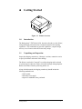
Getting Started
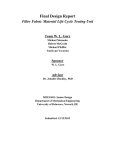
Figure 1-1 Printer Overview
1.0
Introduction
The Bradyprinter THT Model 1024, hereafter referred to as 'the Printer',
incorporates high performance/low cost thermal transfer label printing
capabilities. The combination of powerful capabilities, compact design,
and easy to use features make this Printer truly unique.
1.1
Unpacking and Inspection
Inspect the shipping container(s), if damage is evident, contact the carrier
to specify the nature and extent of the damage.
The Printer is packed in Corrupad recycled packaging and is enclosed
in a plastic bag to reduce the chance of moisture damage during shipment.
Remove the Printer from the plastic bag before use.
Along with this manual, the shipping container(s) should include the
following standard items:
• Label printer
• External power supply
• Special or additional items purchased.
Getting Started
1
1.2
Printer Specifications
Mechanical
Width
8.8" (22.35 cm)
Depth
10.1" (25.65 cm)
Height
6.2" (15.75 cm)
Weight
7 lbs. (15.4 kg)
Operating Temperature
40° F to 100° F (4° C to 38° C)
Printer Specifications
Print Type
Thermal Transfer
Print Speed
1, 1.5, and 2" per second
Resolution
203 dpi (8 dots/mm)
Tear Bar
Tear up
DRAM Memory
512 kb
EPROM Memory
512 kb
Media/Ribbon
Media Types
Roll-Fed, Die-Cut, Continuous, Fan-Fold
Max. Media Width
4.65" (118 mm)
Max. Print Width
4.1" (104 mm)
Min. Print Width
1" (25 mm)
Max. Print Length
12" (305 mm) with standard RAM
Min. Print Length
.375" (.95 cm)
.5" (1.27 cm) w/ Present Sensor
Media Thickness
.0025" - .01" (.0635 mm - .254 mm)
Ribbon
Matched to Media; approx. 4330"(110m)
long
1.5" O.D. on .5" core
2
Getting Started
Communications
Interface
RS-232 (DB-9), and Centronics Parallel
Baud Speed
1200 to 19200 bps
Handshaking
Xon/Off, CTS, DTR
Parity
Even, Odd, or None
Stop Bits
1 or 2
Data Bits
7 or 8
Electrical
External Power Supply
Nominal 115 or 230 VAC IN/ 19 VAC OUT
Fonts
10 Resident Styles
Resident Fonts Expandable to 8x
Reverse Image
Rotated 0, 90, 180, 270 degrees
Available Bar Codes
Code 39, Ext Code 39, Code 93, Ext Code 93, Code 128 UCC, Code 128
A, B & C, Codabar, Interleaved 2 of 5, UPC-A, UPC-E, UPC Ship C
Code, EAN-13, EAN-8, EAN 128, POSTNET, MaxiCode, PDF417
Options
Present Sensor
Memory Cartridges
External Cutter
DRAM Memory, (Expandable to 1MB)
Wall Mount
External Battery
Time/Date
External Media Supply
Getting Started
3
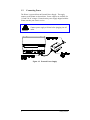
1.3
Connecting Power
The Printer is powered from an External Power Supply. The supply
connects to the Printer as shown below. Power supplies are available for
115 and 230 AC voltages. Ensure that the power supply shipped with the
Printer matches your electric service.
Caution!
Connect power supply to Printer before plugging into AC
outlet.
Figure 1-2 External Power Supply
4
Getting Started
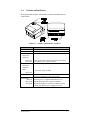
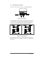
1.4
Switches and Indicators
Descriptions and locations of the Printer's switches and indicators are
shown below.
Figure 1-3 Switches and Indicator Locations
Switch/Indicator
On/Off switch
Feed Button
Printer in
ready state (LED On)
Press twice
Press once
Printer in
alarm state (LED fast
flash)
Press once
Darkness Control
Power LED
Solid On
Slow Flash
Fast Flash
Getting Started
Function
Controls power to the Printer.
Printer feeds media to first print position of next label.
Pauses Printer, press again to resume.
Clears alarm, feeds one label.
Used to balance a new Printhead so that it prints at the
same level of darkness as the previous head.
Indicates power is supplied and the Printer is on.
Indicates the Printer is in a 'paused' condition.
Indicates the Printer is in an 'error' condition such as
Media Out, Ribbon Out (if equipped), or Jam.
5
1.5
Interfacing to the Printer
The Printer can be connected to the host via a serial or parallel cable.
Figure 1-4 Interfacing
For most applications, the interface between the Printer and the Host will
be serial (RS-232C). An interface cable is needed to connect the Printer
to the host. Cable configurations for typical interfaces are shown below,
(contact your reseller for part numbers and ordering information).
Figure 1-5 Interface Cables
Other applications may require a parallel connection from the Printer to
the host. The Printer can be connected to the host with a standard parallel
printer cable.
6
Getting Started
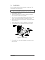
1.6
Loading Media
Due to its design, loading the Printer with media is a simple task. The
following steps outline the procedure.
Note: If your Printer is equipped with the External Media Supply Option
then you would load the media from the rear of the Printer.
1. Open the Printer's Top Cover.
2. Release the Printhead Carrier Assembly by pushing the Printhead
Latch. Raise the Assembly to its up position.
3. Place a roll of the chosen media on the Media Hub and place it in the
Printer. Ensure that the Media Hub is flush against the media.
4. Pull the media forward and out of the Printer. Ensure that the media's
labels are facing up.
5. Slide the Media Guide over until it is against the side of the media.
6. Close the Printhead Carrier Assembly, press down until it latches.
Figure 1-6 Media Loading
7. Close the Top Cover. Press the Feed Button several times to ensure
proper tracking.
Getting Started
7
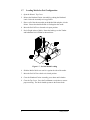
1.7
Loading Media for Peel Configuration
1. Open the Printer's Top Cover.
2. Release the Printhead Carrier Assembly by pushing the Printhead
Latch. Raise the Assembly to its up position.
3. Place a roll of the chosen media on the Media Hub and place it in the
Printer. Ensure that the Media Hub is flush against the media.
4. Move the Peel Off Lever forward to its open position.
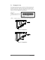
5. Peel off eight inches of labels. Route the backing over the Tearbar
and behind the Peel Off Shaft as shown below:
Figure 1-7 Peel Off Media Loading
6. Slide the Media Guide over until it is against the side of the media.
7. Move the Peel Off Lever back to its closed position.
8. Close the Printhead Carrier Assembly, press down until it latches.
9. Close the Top Cover. Press the Feed Button several times to ensure
proper tracking. The labels should separate as the Printer feeds.
8
Getting Started
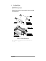
1.8
Loading Ribbon
1. Open the Printer's Top Cover.
2. Remove the two Ribbon Hubs.
3. Slide the ribbon onto the hub ensuring that the ribbon comes off the
roll as shown below.
Figure 1-8 Ribbon Hub Removal
4. Place the Ribbon Supply Hub back into the Thermal Transfer
Assembly.
Getting Started
9
5. Make sure that the Direct/Thermal Transfer Switch is set to the
‘Transfer’ position for thermal-transfer printing.
Figure 1-9 Selecting Print Type
6. Route the ribbon through the Printhead Carrier Assembly as shown.
Figure 1-10 Ribbon Routing
7. Close the Top Cover. Press the Feed Button several times to ensure
proper tracking.
10
Getting Started
1.9 Adjusting for Wide or Narrow Ribbons
The Ribbon Handler has a built in adjustment for controlling tension
on the Ribbon Supply Hub. This adjustment provides for better
results when using different width ribbons.
1. Turn ‘off’ the Printer.
2. Hold the Ribbon Supply Spindle and rotate the Ribbon Tension
Adjustment Knob to meet your printing needs based on the table
below. Ensure that the Ribbon Tension Adjustment Knob is
turned fully to the Clockwise or Counter-Clockwise position.
1-11 Adjustments for media
Direction of Rotation
Clockwise
Counter-Clockwise
Getting Started
Effect
Use this position for narrow ribbons
Use this position for wide ribbons
11
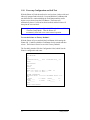
1.10
Power-up Configuration and Self-Test
With the Printer off, load the media to be used (at least 4 inches wide) and
ribbon (if equipped and/or desired). Press and hold the Feed Button and
turn the Printer on, continue holding the Feed Button until the media
begins to move then release the Feed Button. The Printer will
automatically detect if a ribbon has been installed, and the Printer will
then print the two test labels.
Note: After performing a Power-Up and Self-Test, the Printer will be in
'Character Dump Mode'. Turn the Printer off
momentarily, then back on to restore normal operation.
To reset the Printer to 'Factory Defaults':
With the Printer off, press and hold the Feed Button while turning the
Printer ON. Continue to hold the Feed Button for 60 seconds and then
release. The Printer will now be set to the 'Factory Defaults'.
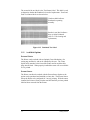
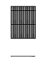
The first label printed will be the Configuration Label, which lists the
Printer's configuration and status.
FRI SEPTEMBER 026,
1995 19:29 244
ROM CHECKSUMS
U09
U10
SYSTEM RAM CHECKS____ GOOD
KBYTES
SYSTEM RAM SIZE__ 512
CONFIGURATION
9600,8,N
DIRECT
INPUT VALUES
PAPER: 228 EDGE: 179 REFL:
POT : 212 TOFA: 133 RIBN:
COUNTER INFORMATION
ABSOLUTE VALUES 9-18-1994
1994
LENGTH____
773 INCHES
INCHES
TIME______
10 HOURS
HOURS
0 TEMP:
0
89
RESETABLE VALUES 9-18LENGTH____
576
TIME______
4
MEMORY CONFIGURATION
12
Getting Started
INTERNAL MODULE______
10
12
SCALABLE FONTS_______
Figure 1-11 Configuration Test Label
Getting Started
13
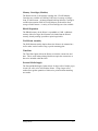
The second of the two labels is the Test Pattern Label. This label is used
to determine whether the Printhead is in need of replacement. 'Good' and
'Bad' Test Pattern labels are shown below:
Good test label indicates
Printhead is operating
normally.
Streaks in test label indicate a
dirty or faulty Printhead.
(See Ch. 3 for cleaning and
replacement).
Figure 1-12 Printhead Test Label
1.11
Available Options
External Cutter
The Printer can be ordered with an Optional Cutter Mechanism, (for
cutting tags and labels), and can be installed by the user. The Cutter
Option easily attaches to the front of the Printer and its modular cable
plugs into the back. When properly installed the cutter will cut each label
as it is printed.
Present Sensor
The Printer can either be ordered with the Present Sensor Option or the
option can be purchased and installed at a later date. The Present Sensor
allows the Printer to be configured for "one up" printing. With the sensor
installed, the Printer will not print the next label until the previous printed
label has been removed from the Printer.
14
Getting Started
Memory Cartridges (Modules)
The Printer has one 16 bit memory cartridge slot. FLASH Memory
Cartridges are available in 256K and 512K sizes for storage of images,
fonts, or label formats. An Internal Batch Labeling Software Cartridge is
available that contains 256K of FLASH Memory on-board for direct
storage of label formats. A variety of Font Cartridges are also available.
DRAM Expansion
The DRAM memory in the Printer is expandable to 1 MB. Additional
memory allows for larger label formats to be loaded into the Printer's
memory, thereby making it possible to print longer labels.
Wall Mount Assembly
The Wall Mount Assembly Option allows the Printer to be mounted to a
wall or other vertical surface using a special mounting plate.
Time/Date
The Time/Date Option allows the Printer to retain the current time and
date. This is useful when printing labels that require the current time or
date to be included within the label.
External Media Supply
The External Media Supply Option allows for larger rolls of media, (up to
8 inch O.D. rolls), to be used with the Printer. Using a larger roll of
media allows greater quantities of labels to be printed without installing
new media.
Getting Started
15
♦
Printing Labels
2.0
Introduction
This chapter explains how to generate labels using several different
methods and how to print different bar codes. An optional Internal Batch
Cartridge is available for generating label formats using the Printer as a
standalone device.
A LINK MC2 or compatible CRT is required if the optional Internal
Batch Cartridge is used. The optional Internal Batch Cartridge works
much like a PC-compatible software package, but uses Cartridges instead
of hard or floppy disk drives to store and retrieve label formats.
Labels can also be generated using RS-232 or parallel communications to
a host computer or a PC with a compatible labeling software package.
This chapter explains some of the basic programming commands that are
required when writing programs to generate label formats. A
programmer's manual can be obtained by mailing or faxing the request
card located in the back of this manual.
16
Printing Labels
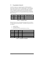
2.1
Programming Commands
In order to be ready for a command sequence, the Printer must first
receive a special character called an “attention getter” which informs the
Printer that it is about to receive a command and the type of command it
will be. Immediate Commands, System Level Commands, and Font
Loading Commands each have their own attention getter. The attention
getter character is followed by a command character that tells the Printer
what action to take.
ASCII
Char.
SOH
STX
ESC
Decimal
Value
1
2
27
HEX
Value
01
02
1B
DOS
Prompt
Ctrl A
Ctrl B
Ctrl [
Attention Getter For
Immediate Commands
System Level Commands
Font Loading Commands
Table 2-1 Attention Getters
When the Printer receives an Immediate Command it will cease whatever
it is doing and perform that command. Commands of all types must be in
this sequence:
1.
2.
3.
Attention Getter
Command Character
Parameters that must be entered by the user (if any).
Command
Character
Must Enter
Parameters?
Printer
Responds?
#
A
B
C
D
E
F
N
N
N
N
N
N
N
Y
Y
N
N
N
Y
Y
Command
Reset
Send ASCII status string
Toggle pause
Cancel
SOH shutdown
Send batch quantity
Send status byte
Table 2-2 Immediate Commands
Printing Labels
17
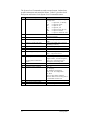
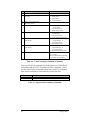
The System Level Commands are used to create formats, load and store
graphic information, and control the Printer. Table 2-3 provides a brief
description and format of each System Level Command character.
Char
Description
A
Set time and date
a
Enable feedback characters
B
c
Get Printer time and date information
Set continuous paper length
d
Set Printer to double buffer mode
E
e
F
f
Set quantity for stored label
Select edge sensor
Form feed
Set form stop position (backfeed)
G
I
Print last label format
Input graphics data block
i
J
K
"See Programmer's Manual for
format"
Download scalable font
Set pause for each label
Extended System Commands
k
L
M
Test RS-232 Port with a Y if OK
Enter Label Formatting Mode
Set maximum label length
18
Format
FORMAT: AwmmddyyyyhhMMjjj
16 digits total.
= 1 digit week, 1 is Monday
w
= 2 digits for month
mm
= 2 digits for day
dd
yyyy = 4 digits for year
= 2 digits for hour (24 hr ft)
hh
MM = 2 digits for minutes
= 3 digits for Julian I.D. value
jjj
Returns 30 after each label and 31 after
each batch of labels
Print time and date to port
cnnnn = length of paper to feed per
label
Use to print a label while a second is
formatting in memory
Ennnn = Set Quantity for stored label
for "see through" media sensing.
Feeds one label at a time
Set distance to peel (tear off) position
fnnn = 3 digits from sensor
A bank designation, an optional word
length modifier, a format designation,
and up to a 16-character string to
identify the stored image data
Kn n =
Q - For query
D - Database Configuration
S, W, or M - Set configuration
R - Reset
fxxxx- 4 digit number, Distance
between TOF sensor and stop position
r - Resettable counters reset
Sends character "Y" to RS-232 port
Mnnnn = 4 digits Max. 12. inches
Printing Labels
Table 2-3 System Level Commands
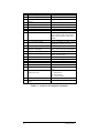
Printing Labels
19
Char
Description
m
Set metric flag, enter metric mode
n
Clear metric flag, return to inch mode
O
Form edge offset (start of print
position)
o
Cycle cutter
P
Enter character dump mode
p
Controlled pause
Q
Clear all memory modules
q
Clear module
r
Select reflective sensor
S
s
Slew (feed) speed
Set up for one print buffer
T
t
U
V
Printhead dot pattern test label
Test RAM memory module
(Must be in Test Mode)
Label format field replacement
Software switch settings
v
W
w
x
X
Y
Firmware version information
Request memory module information
Test FLASH module memory
Delete module file
Set default module bank
Output sensor values
y
Select Font Symbol Set (Optional
scalable fonts only)
z
Z
Pack module
Print internal information and dot
pattern
Format
All references set to metric until reset
Onnnn = 4 digits, in/100 or mm/10
gx = Module I.D. (Uppercase)
Used for "black-strip" media sensing,
(e.g. continuous tags, butt-cut labels.
Stripe must be printed on back side of
media)
Sx x = A -C (1.0 to 2.0 ips)
Set for 1 dot buffer processing. Use for
full length dot buffer processing.
a bbbK Module Good
bbb = 256 or 512, for size of module
Vn n = 4-Label Present, 2-Internal
Batch, 1-Cutter Enable
Sends version string to Host
Wx x = F-font, G-graphic, L-label
Takes about 90 seconds
xMFname M=Module I.D, F=file type
Xa a - A = Memory Module A
Dumps sensor values status to RS-232
port
y S xx
y = ASCII (0x79)
S = ASCII (0x54)
xx = symbol selection
Zx x= Module I.D
Table 2-3 System Level Commands (Continued)
20
Printing Labels
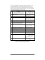
A STX L Command switches the Printer from the System Level to the
Label-Formatting Mode. All command characters after STX L are
interpreted as Label Formatting Commands until the Label Formatting
mode is terminated with the command character E. All Label Formatting
Commands are terminated with hex value 0D.
CC
Description
Set
cut
by
amount
(4 digits)
:
The cutter function will perform a cutting
action after the number of labels specified.
A Set format attribute
C
c
D
Set column offset amount
Set cut by amount (2 digits)
Set height and width dot size
E
G
H
Terminate field generation and print label
Place data in global register
Enter heat setting
(The amount of heat applied per dot row, can
be used to help control print quality)
Set metric mode
Format
:nnnn
nnnn = 4 digits of labels printed
before cut. Default = 0001
An n=1-XOR, 2-Transparent, 3Opaque, 5-Inverse
Cnnnn nnnn= in/100 or mm/10
cnn nn = 2 cut amount
h = Horiz. dot size; can be 1 or 2
v = Vert. dot size; can be 1,2, or 3
(0.005" steps) Default is “D22”
m
M
P
p
Q
R
r
Set mirror image mode
('Mirror Images' current formatted label)
Print speed
Set label backup speed
Enter quantity of labels to print
Set row offset amount
Recall stored label format
S
s
Slew (feed) speed
Store label format in module
T
Set field data line terminator
U
Make previous field a string replace field
Hnn nn = 2 digits. 1 - 30
10 is nominal and default
The Printer must be reset in
order to return to standard
measure
'M' must be re-sent to cancel.
* Will not mirror polygons.
Px x x = A -C (1.0 to 2.0 ips)
px x x = A -C (1.0 to 2.0 ips)
Qnnnn nnnn = quantity
Rnnnn nnnn = in/100 or mm/10
rnn...n nn...n Label name of up
to 16 char. terminated by CR.
Sx x x = A -C (1.0 to 2.0 ips)
sann...n a - destination module
A Memory Module A
nn...n - label name (16 char.
max)
Tnn nn = 2 digit ASCII Hex
00 - FF
Table 2-4 Label-Formatting Commands
Printing Labels
21
CC
Description
X Terminate label formatting mode
y Select font symbol set (optional scalable
fonts only)
z or Zero (0) conversion to "O"
Z eliminates slash (/)
+ Make last field entered increment numeric
-
Make last field entered decrement numeric
>
Make last field entered increment
alphanumeric
<
Make last field entered decrement
alphanumeric
^
Set count by amount
Format
y S xx
y = ASCII (0x79)
S = ASCII (0x54)
xx = symbol selection
+pii Make last entered field
incrementing
p = Zero fill character
ii = Data added to field
-pii Make last entered field
decrementing
p = Zero fill character
ii = Data subtracted from field
>pii Make last entered field
incrementing 0 - Z
p = Zero fill character
ii = Data added to field
<pii Make last entered field
decrementing 0 - Z
p = Zero fill character
ii = Data subtracted from field
^nn Set count by amount
nn = 2 digits
Skip # of labels before updating
count fields and time fields
Table 2-4 Label Formatting Commands (Continued)
There are two special commands used by the Printer, the STX S (Recall
Global Data) and the STX T (Print Date and Time) commands. Unlike
the other Label Format Commands, which follow the STX L command,
these special commands are entered directly into the data field.
Character
<STX>S
<STX>T
Description
Recall global data and place in field
Print time and date
Table 2-5 Special Label Formatting Commands
22
Printing Labels
The commands used for bit mapped font loading are usually generated by
font-creation software. However, the Assign Font ID Number command
must be sent to the Printer before the font file. Font Loading Commands
are listed in Table 2-6.
The following sample program is included for reference. The ASCII text
file below will generate the label shown in Figure 2-1.
Command
Character
P
PR
*c###D
N
N
Description
Assign Font ID Number
### = ID Number 100 to 999
P = Must Supply Parameters?(Y/N)
PR = Printer Responds? (Y/N)
Table 2-6 Font Loading Commands
2.2
Programming Examples
<STX> L <CR>
H07 <CR>
D11 <CR>
19110080100002510K OHM 1/4 WATT <CR>
1a6210000000050590PCS <CR>
E
10K OHM 1/4 WATT
Figure 2-1 Sample Label
Printing Labels
23
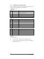
2.3
Configuration Command String
The Configuration Command String sets the operating parameters of the
Printer. The Command Strings are described below.
<STX>KDwxy <CR>
where w:
Bit # Function
0-2
Baud Rate
Value
3
4&5
6
7
0=8 bits, 1=7bits
Set to 0
Set to 1
Set to 0
Word Length
Unused
Always 1
Always 0
where x:
Bit # Function
0
Print Method
1
Present Sensor
2
Alternate Char.
Set
3
Cutter
4&5 Unused
6
Always 1
7
Always 0
where y:
Bit # Function
0&1 Paper Type
2
Linerless
3-5
Unused
6
Always 1
7
Always 0
0=9600, 1=600, 2=2400, 3=19200, 4=4800, 5=N/A,
6=1200, 7=9600 Test Mode
Value
0=direct, 1=transfer
0=not equipped, 1=equipped
0=standard, 1=main frame
0=disabled, 1=enabled
Set to 0
Set to 1
Set to 0
Value
0=gap(edge), 1=reflective, 2=continuous (3")
0=not equipped, 1=equipped
Set to 0
Set to 1
Set to 0
Example:
<STX>KD @A@ <CR>
@
Sets the Printer to: 9600 baud; 8 bit word length/no parity.
A
Sets the Printer to: thermal transfer; no present sensor; standard
character set; no cutter.
24
Printing Labels
@
Sets the Printer to: gap (edge) media; no linerless.
Printing Labels
25
2.4
Printing Bar Codes
The example shown below prints out a Code 3 of 9 bar code with a wide
to narrow bar ratio of 3:1 and can be used to print any of the bar codes
shown in Appendix B by altering the example's fields. Refer to Figures 22 and 2-3 for a brief explanation of the data fields.
<STX>L<CR>
D11<CR>
1A93040001501000123456789<CR>
121100000000100Barcode A<CR>
E
<STX>L
Syntax L on line 1 is used to enter the label formatting mode.
Figure 2-2 Example line 3
Figure 2-3 Example line 4
26
Printing Labels
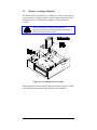
2.5
Memory Cartridges (Modules)
The Printer has one 16 bit Memory Cartridge Slot. There are four storage
uses for Memory Cartridges: graphic images; smooth formed fonts; label
formats that can be recalled by host computers; and internal batch
formats.
Caution!
The use of Memory Cartridges other than those
specifically designed for the Printer can cause damage to
both the Cartridge and the Printer.
Figure 2-4 Inserting Memory Cartridge
When turned on the Write Protect Switch will not allow data to be written
to the Cartridge, ensuring that important data is not overwritten.
Printing Labels
27
♦
Maintenance
3.0
Introduction
This chapter will cover the cleaning, adjusting, and some troubleshooting
tips involved with your Printer.
3.1
Cleaning the Printhead
Warning: Turn ‘off’ the Printer and unplug the unit from the outlet
before cleaning the Printhead.
The Printhead should be cleaned every time a new roll of media is
installed. Follow the instructions below for proper cleaning.
1. Turn OFF the Printer, open the Top Cover.
2. Unlatch the Printhead Assembly, raise it to its up position.
3. Using a cotton swab dipped in isopropyl alcohol, clean the Printhead
by rubbing the cotton swab along the Printhead.
Figure 3-1 Cleaning Printhead
28
Maintenance
3.2
Media Width Adjustment
The Thumbwheel on the side of the Printhead Carrier allows the Printhead
to be adjusted for media narrower than the width of the Printhead. The
numbers on the Thumbwheel do not correspond to a particular media
width but serve only as a reference point.
Figure 3-2 Adjusting Media Width
1. Load the Printer with the chosen media.
2. Begin printing labels. The internal Test Pattern Label can be used or
any other label sent from the Host.
3. Rotate the Thumbwheel left
until the print quality along
edge starts to lighten.
4. Then rotate the Thumbwheel
right just enough to achieve
uniform print quality across
the label.
Maintenance
29
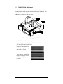
3.3
Fine Printhead Adjustment
An Allen set screw is located on top of the Printhead Carrier Assembly
that can be adjusted for controlling print quality. This adjustment is set at
the factory and should not need further adjusting, however with different
types and thickness of media some adjustment may be necessary.
To adjust the Printhead, turn the set screw until optimum print quality is
obtained, (some trial and error may be necessary).
Figure 3-3 Fine Printhead Adjustment
30
Maintenance
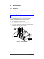
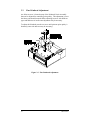
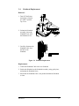
3.4
Printhead Replacement
Removal:
1. Turn OFF the Printer
and unplug it from the
AC outlet. Open the
Top Cover.
2. Unlatch the Printhead
Assembly, loosen the
Printhead Screw until
the Printhead is free.
3. Carefully disconnect the
Printhead Cable from
the back of the
Printhead.
Figure 3-4 Printhead Replacement
Replacement:
1. Connect the Printhead Cable to the new Printhead.
2. Position the Printhead on the Printhead Assembly, (using guide pins),
and tighten the Printhead Screw.
3. Ensure that the Printhead Cable is not pinched and that the Printhead
is clean.
Maintenance
31
Appendix A
ASCII Control Code Chart
Char
NUL
SOH
STX
EXT
EOT
ENQ
ACK
BEL
BS
HT
LF
VT
FF
CR
SO
SI
DLE
DC1
DC2
DC3
DC4
NAK
SYN
ETB
CAN
EM
SUB
ESC
FS
GS
RS
US
Dec
0
1
2
3
4
5
6
7
8
9
10
11
12
13
14
15
16
17
18
19
20
21
22
23
24
25
26
27
28
29
30
31
Note:
Appendix A
Hex
00
01
02
03
04
05
06
07
08
09
0A
0B
0C
0D
0E
0F
10
11
12
13
14
15
16
17
18
19
1A
1B
1C
1D
1E
1F
Char
!
Ò
#
$
%
&
Ô
(
)
*
+
,
.
/
0
1
2
3
4
5
6
7
8
9
:
;
<
=
>
?
Dec
32
33
34
35
36
37
38
39
40
41
42
43
44
45
46
47
48
49
50
51
52
53
54
55
56
57
58
59
60
61
62
63
Hex
20
21
22
23
24
25
26
27
28
29
2A
2B
2C
2D
2E
2F
30
31
32
33
34
35
36
37
38
39
3A
3B
3C
3D
3E
3F
Char
@
A
B
C
D
E
F
G
H
I
J
K
L
M
N
O
P
Q
R
S
T
U
V
W
X
Y
Z
[
\
]
^
_
Dec
64
65
66
67
68
69
70
71
72
73
74
75
76
77
78
79
80
81
82
83
84
85
86
87
88
89
90
91
92
93
94
95
Hex
40
41
42
43
44
45
46
47
48
49
4A
4B
4C
4D
4E
4F
50
51
52
53
54
55
56
57
58
59
5A
5B
5C
5D
5E
5F
Char
`
a
b
c
d
e
f
g
h
i
j
k
l
m
n
o
p
q
r
s
t
u
v
w
x
y
z
{
|
}
~
Dec
96
97
98
99
100
101
102
103
104
105
106
107
108
109
110
111
112
113
114
115
116
117
118
119
120
121
122
123
124
125
126
127
Hex
60
61
62
63
64
65
66
67
68
69
6A
6B
6C
6D
6E
6F
70
71
72
73
74
75
76
77
78
79
7A
7B
7C
7D
7E
7F
For the software handshake XON/XOFF commands:
XON=(DC1)
XOFF =(DC3)
A-1
Char
Dec
Hex
Char
Dec
Hex
Dec
Hex
Char
Dec
Hex
Ç
128
80
á
160
A0
192
C0
Ó
224
E0
ü
129
81
í
161
A1
193
C1
ß
225
E1
é
130
82
ó
162
A2
194
C2
Ô
226
E2
â
131
83
ú
163
A3
195
C3
Ò
227
E3
ä
132
84
ñ
164
A4
196
C4
õ
228
E4
à
133
85
Ñ
165
A5
197
C5
Õ
229
E5
å
134
86
ª
166
A6
ã
198
C6
µ
230
E6
ç
135
87
°
167
A7
Ã
199
C7
þ
231
E7
ê
136
88
¿
168
A8
200
C8
Þ
232
E8
ë
137
89
®
169
A9
201
C9
Ú
233
E9
è
138
8A
170
AA
202
CA
Û
234
EA
ï
139
8B
1/2
171
AB
203
CB
Ù
235
EB
î
140
8C
1/4
172
AC
204
CC
ý
236
EC
ì
141
8D
¡
173
AD
205
CD
Ý
237
ED
Ä
142
8E
174
AE
206
CE
238
EE
Å
143
8F
175
AF
207
CF
239
EF
É
144
90
176
B0
ð
208
D0
240
F0
æ
145
91
177
B1
Ð
209
D1
241
F1
Æ
146
92
²
178
B2
Ê
210
D2
242
F2
ô
147
93
³
179
B3
Ë
211
D3
243
F3
ö
148
94
´
180
B4
È
212
D4
244
F4
ò
149
95
Á
181
B5
213
D5
245
F5
û
150
96
Â
182
B6
Í
214
D6
÷
246
F6
ù
151
97
À
183
B7
Î
215
D7
¸
247
F7
ÿ
152
98
©
184
B8
Ï
216
D8
º
248
F8
Ö
153
99
¹
185
B9
217
D9
¨
249
F9
Ü
154
9A
186
BA
218
DA
·
250
FA
ø
155
9B
187
BB
219
DB
251
FB
£
156
9C
188
BC
220
DC
252
FC
Ø
157
9D
¢
189
BD
221
DD
253
FD
x
158
9E
¥
190
BE
222
DE
254
FE
ƒ
159
9F
191
BF
223
DF
255
FF
A-2
¯
»
Char
Ì
±
3/4
Appendix A
Appendix B
Available Fonts and Bar Codes
All character fonts and bar codes available with the Printer are described
in this section. Each font and bar code has a name associated with it for
use in programming. Human-readable fonts have numeric names while
bar code fonts have alpha names. Uppercase alpha names will print bar
codes with human readable interpretations. Lowercase alpha names will
print bar codes only.
Fonts
Fonts 0 through 8 use the slash zero (Ø) conventions for distinguishing
between the zero and the alphabetic O. The slash can be removed with the
label formatting command Z. These fonts are non-proportional
(monospaced) fonts; all of the characters take up the same amount of
space when printed. This is helpful when using variable data in a fixed
area. The sizes of these fonts are shown in Table B-1.
The Triumvirate font number 9 is a proportional font; each character will
take up a different amount of space when printed. For example, the letter
W will be larger than the letter I.
Font
0
1
2
3
4
5
6
7
8
9
Valid ASCII Characters
32-127
32-168, 171, 172, 225
32-168, 171, 172, 225
32, 35-38, 40-58, 65-90, 128, 142-144, 146, 153, 154,
156, 157, 165, 168, 225
32, 35-38, 40-58, 65-90, 128, 142-144, 146, 153, 154,
156, 157, 165, 168, 225
32, 35-38, 40-58, 65-90, 128, 142-144, 146, 153, 154,
156, 157, 165, 168, 225
32, 35-38, 40-58, 65-90, 128, 142-144, 146, 153, 154,
156, 157, 165, 168, 225
32-126
32, 48-57, 60, 62, 67, 69, 78, 83, 84, 88, 90
32-126, 128-169, 171-173, 181-184, 189, 190, 198, 199, 208-216,
222, 224-237, 241, 243, 246-250
Table B-1 Valid Human Readable Font ASCII Characters
Appendix B
B-1
Table B-2 lists the font sizes. The numbers indicate the number of dots.
FONT
Font 0
Font 1
Font 2
Font 3
Font 4
Font 5
Font 6
Font 7
Font 8
HEIGHT
7
13
18
27
36
52
64
32
28
WIDTH
5
7
10
14
18
18
32
15
15
SPACING
1
2
2
2
3
3
4
5
5
Table B-2 Font Sizes
Font 0 96-character
alphanumeric, upper and lower
case.
Font 1 145-character upper and
lower case alphanumeric w/
descenders and ascenders.
Font 2 138-character alphanumeric,
upper and lower case.
Font 3 62-character
alphanumeric, uppercase.
B-2
Appendix B
Font 4 62-character
alphanumeric, uppercase.
Font 5 62-character
alphanumeric, uppercase.
Font 6 62-character alphanumeric, uppercase.
Appendix B
B-3
Font 7 OCR-A, size I.
Font 8 OCR-B, size III.
Font 9 Internal Triumvirate font.
Point sizes are selected by the number in the bar code height.
Larger point sizes can be obtained by increasing the height and width
multipliers (see the Programmer's Manual for more information).
B-4
Appendix B
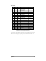
Bar Codes
Font
A
B
Length
Varies
11
Cksum
No
Yes
C
D
E
F
6
Varies
Varies
12
Yes
No
M-103
Yes
G
H
I
J
K
7
Varies
Varies
Varies
Up to
14
Yes
M-43
No
M-10
M-10
L
M
N
O
p
Q
R
S
T
u
v
z
13
2
5
Varies
Varies
19
18
34 +
Varies
84
1
Varies
M-10
Yes
Yes
No
Yes
Yes
Yes
Yes
Yes
Yes
No
Yes
Valid ASCII Characters
32, 36, 37, 42, 43, 45-57, 65-90
48-57 Numeric only
Option V used in the
6th & 7th position
48-57 Numeric only
48-57 Numeric only
32-127
48-57 Numeric only
Option V used in the
7th & 8th position
48-57 Numeric only
32, 36-39, 42, 43, 45-57, 65-90
36, 43, 45-58, 65-68
48-57 Numeric only
48-57 Numeric only
Option + is Last Character
for Second M-11 Checksum
48-57 Numeric only
48-57 Numeric only
48-57 Numeric only
0 - 127 ASCII characters
48-57 Numeric only
48-57 Numeric only
48-57 Numeric only
48-57 Numeric only
0 - 127 ASCII characters
Alpha numeric
A, B, C, D
All
Bar widths
2:1 - 3:1
2:1 - 4:1
2:1 - 4:1
2:1 - 3:1
2:1 - 4:1
2:1 - 4:1
2:1 - 4:1
2:1 - 3:1
2:1 - 3:1
2:1 - 3:1
2:1 - 3:1
2:1 - 3:1
2:1 - 4:1
2:1 - 4:1
2:1 - 4:1
Same as fonts
2:1 - 4:1
2:1 - 4:1
2:1 - 4:1
2:1 - 4:1
N/A
Same as fonts
Any Ratio
Table B-3 Bar Code Characteristics
Uppercase bar code identifiers (I.D's) have corresponding lowercase I.D's
that when selected suppress printing of associated human-readable text.
Appendix B
B-5
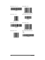
Bar Code A Code 3 of 9
Bar Code B UPC-A
Bar Code C UPC-E
Bar Code D Interleaved 2 of 5
Bar Code E Code 128
Bar Code F EAN-13
Bar Code G EAN-8
Bar Code H Health Industry Bar
Code
(HBIC)
B-6
Appendix B
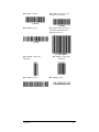
Bar Code I Codabar
Bar Code J Interleaved 2 of 5
w/modulo 10 checksum
Bar Code K Plessey
Bar Code L Interleaved 2 of 5
w/modulo 10 checksum and
shipping bearer bars
Bar Code M 2 Digit UPC
addendum
Bar Code O Code 93
Appendix B
Bar Code N 5 Digit UPC
addendum
Bar Code p Postnet
B-7
Bar Code Q UCC/EAN Code 128
Bar Code R UCC/EAN Code 128
KMART NON EDI
Bar Code S UCC/EAN Code 128
Random Weight
Bar Code T Telepen
Bar Code u UPS MaxiCode
Bar Code v FIM
Bar Code z PDF-417
B-8
Appendix B
Appendix C
Error Codes
The error codes that may be transmitted by the Printer are described here.
Lowercase "v"
There is an input buffer overflow situation.
Uppercase "R"
This code is sent every time the Printer is turned ON. It signals that there
was a hardware reset.
Uppercase "T"
This code signals that there was a software reset. A software reset results
from sending the <SOH># command sequence to the Printer or by doing a
front panel reset.
Appendix C
C-1
C-2
Appendix C
Appendix D
Warranty Information
Brady
Limited Warranty Statement
Bradyprinter THT Model 1024
Printer
Brady warrants to Purchaser that under normal use and service, the
Bradyprinter THT Mode 1024, (with the exception of the thermal
Printhead) purchased hereunder shall be free from defects in material and
workmanship for a period of (365) days from the date of shipment by
Brady.
Expendable and/or consumable items or parts such as lamps, fuses, labels
and ribbons are not covered under this warranty. This warranty does not
cover equipment or parts which have been misused, altered, neglected,
handled carelessly, or used for purposes other than those for which they
were manufactured. This warranty also does not cover loss, damages
resulting from accident, or damages resulting from unauthorized service.
Thermal Printhead
This warranty is limited to a period of ninety (90) days, or 1,000,000
linear inches of use, whichever comes first, for the Bradyprinter THT
Model 1024. This ninety (90) day warranty is valid only if Bradyapproved thermal transfer label media is used. Failure to use Bradyapproved media is justification for invalidation of this thermal Printhead
warranty. This warranty does not cover Printheads which have been
misused, altered, neglected, handled carelessly, or damaged due to
improper cleaning or unauthorized repairs.
Appendix D
D-1
Warranty Service Procedures
If a defect should occur during the warranty period, the defective unit
shall be returned, freight and insurance prepaid, in the original shipping
containers, to Brady at: 6555 Good Hope Road, Milwaukee, WI 53223.
An RMA (Return Material Authorization) number must be issued before
the product can be returned. To open an RMA please call Brady's
customer service department at 1-800-537-8791. Please include your
RMA number on the outside of the box and on the shipping document.
Include a contact name, action desired, a detailed description of the
problem(s), and examples when possible with the defective unit. Brady
shall not be responsible for any loss or damages incurred in shipping. Any
warranty work to be performed by Brady shall be subject to Brady's
confirmation that such product meets Brady's warranty. In the event of a
defect covered by its warranty, Brady will return the repaired or replaced
product to the Purchaser at Brady's cost.
With respect to a defect in hardware covered by the warranty, the
warranty shall continue in effect until the end of the original warranty
period, or for sixty (60) days after the repair or replacement, whichever is
later.
General Warranty Provisions
Brady makes no warranty as to the design, capability, capacity or
suitability of any of its hardware, supplies, or software.
Software is licensed on an ‘as is’ basis without warranty. Except and to
the extent expressly provided herein, and in lieu of all other warranties,
there are no warranties expressed or implied, including, but not limited to
any warranties of merchantability or fitness for a particular purpose.
Purchaser shall be solely responsible for the selection, use, efficiency and
suitability of Brady's products.
D-2
Appendix D
Limitation of Liability
In no event shall Brady be liable for any indirect, special, or consequential
damages or lost profits arising out of, or relating to Brady’s products, or
the performance or nonperformance thereof, even if Brady has been
advised of the possibility thereof. Brady’s liability, if any, to its purchaser
or to any customer(s) of its purchaser shall in no event exceed the total
amount paid to Brady by the initial purchaser of the defective product.
In the event any implied warranties, (including, but not limited to, the
implied warranties of merchantability and fitness for a particular
purpose), are found to exist, such warranties are limited in duration to the
period of the warranties set forth above.
Some States do not permit the exclusion of incidental or consequential
damages, and in those States the foregoing limitations may not apply. The
warranties here give you specific legal rights, and you may have other
legal rights which vary from State to State.
Appendix D
D-3
Insert Free Roll of Labels
reply card for the 1024
Printer.
(Do not print this page with the manual! Replace
this reminder note with the reply card)
Appendix D
D-1