1
© 2015 Digital Monitoring Products
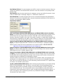
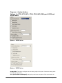
Click on the Contents tab for the Table of Contents.
Click on the Index tab for an alphabetical listing of help topics.
To search for an item, click on the Contents tab and then on the Find tab.
While working in Remote Link, you may press F1 at any time for contextual help specific to the field
that is currently active.
(This Help File is current for Version 1.74)
Remote Link™
© 2000 - 2015 Digital Monitoring Products, Inc.
The Information in the help file is subject to change without notice. The software program described
herein is furnished under the included license Agreement. The software may be used or copied only in
accordance with the terms of the agreement.
No part of this document may be reproduced or transmitted in any form or by any means, electronic,
or mechanical, including photocopying, recording, or information storage and retrieval systems, for
any purpose other than the purchaser's personal use, without the express written permission of Digital
Monitoring Products, Inc.
IBM is a trademark of International Business Machines Corporation
Windows ™ is a trademark of Microsoft ® Corporation
Unless otherwise noted, all names of companies, street addresses, and persons contained herein are
part of a completely fictitious scenario and are designed solely to document the use of the Remote
Link™ program.
© 2015 Digital Monitoring Products
Remote Link™ Software Product License Agreement
© 2000 - 2014 Digital Monitoring Products, Inc.
The terms of this Software Product License Agreement ("SPLA") for the Software Product(s) System
Link™ and/or Remote Link™ are effective immediately upon you (either a single entity or individual)
accepting a copy of the Software Product and the first use of it by you, your employees, or an
authorized subcontractor. These Software Products are protected by copyright laws and international
copyright treaties, as well as other intellectual property laws and treaties. These Software Products
are licensed, not sold.
Therefore, subject to the terms and conditions of this SPLA, your Provider Digital Monitoring
Products, Inc., will provide you with a copy of Remote Link™ or, in the case of System Link™, your
Provider either Digital Monitoring Products, Inc., or one of its authorized representatives will provide
you with a copy System Link™ (which System Link™ and Remote Link™ singly or collectively according
to context herein are referred to as the Software Product). You may not use the Software Product until
you have read and accepted all of the terms of this SPLA by checking the "I accept" checkbox and
clicking the "Finish" button. Digital Monitoring Products, Inc., (or "DMP") is the holder of the
intellectual property holdings embodied in System Link™ and Remote Link™, including without
limitation software modules such as Advanced Reporting, Alarm Monitoring, Command Center,
Account Groups, Link Server, or SQL Server.
System Link™ and Remote Link™ include computer software and associated media, printed materials,
and "online" or electronic documentation (referred to collectively or singly according to context as the
Software Product). The System Link™ and Remote Link™ also include any updates, "plug-ins," modules
and/or supplements to the original System Link™ or Remote Link™ provided to you by DMP or
authorized representative.
By installing, copying, downloading, accessing or otherwise using System Link™ and/or Remote Link™,
you agree to be bound by the terms of this SPLA. If you do not agree to the terms of this SPLA, do not
install or use the Software Product. You may, however, return it for a full refund.
1. Permitted Uses and Restrictions on Use
A Remote Link™ licensee may install and use its DMP provided copy and install and use additional
copies on any number of computers including a network server as well as laptops for the limited
purposes of providing support service to end-users of Digital Monitoring Product, Inc.'s panel products
and allied lines of alarm and security communications equipment; provided that all users are either
employees of said Remote Link™ licensee or authorized subcontractors who are comparably restricted
in usage of the Remote Link™ product, namely, that being for the limited purposes of providing
support service to end-users of Digital Monitoring Product, Inc.'s panel products and allied lines of
alarm and security communications equipment. A Remote Link™ licensee and/or every Remote Link™
user agrees not to copy, sell, resell, rent or sub-license (including offering Remote Link™-or any
derivation or component thereof-to third parties on an applications service provider or time-sharing
basis), lease, loan, redistribute, or create a derivative work of any portion of Remote Link™, or
provide use of Remote Link™, or access to Remote Link™ in competition with sales or uses of System
Link™ for and by end-users of Digital Monitoring Product, Inc.'s panel products and allied lines of alarm
and security communications equipment.
A System Link™ licensee may install and use one copy of System Link™ on a single computer, including
network server, for the purpose of providing communications management of Digital Monitoring
© 2015 Digital Monitoring Products
Product, Inc.'s panel products and allied lines of alarm and security communications equipment;
provided that all such Digital Monitoring Product, Inc.'s panel products and allied lines of alarm and
security communications equipment have duly registered accounts with Digital Monitoring Product,
Inc., or authorized representative thereof. It being further provided that, all parties hereto
contemplate that various devices including without limitation printers and the like are indeed
communicators to a System Link™ machine but are not bound to be assigned an account. A System
Link™ licensee agrees not to copy, sell, resell, rent or sub-license (including offering System Link™-or
any derivation or component thereof-to third parties on an applications service provider or timesharing basis), lease, loan, redistribute, or create a derivative work of any portion of System Link™,
or provide use of System Link™, or access to System Link™ in competition with other sales or uses of
System Link™ for and by other end-use parties of Digital Monitoring Product, Inc.'s panel products and
allied lines of alarm and security communications equipment.
2. Your Registration Obligations
In consideration of your use of the Software Product, you agree to: (a) provide true, accurate, current
and complete information about yourself as prompted your Provider's registration form(s) (such
information being the "Registration Data") and (b) maintain and promptly update the Registration
Data to keep it true, accurate, current and complete. If you provide any information that is untrue,
inaccurate, not current or incomplete, or the Provider has reasonable grounds to suspect that such
information is untrue, inaccurate, not current or incomplete, the Provider may suspend or terminate
your license and you must discontinue any and all current or future use of the Software Product (or any
portion thereof).
3. Fees
You agree to pay the then-current license fee associated with obtaining a copy of the Software
Product. Your Provider reserves the right to modify its fee schedule with or without notice. For
instance, each of one copy of either the native Remote Link™ product or the native System Link™
product will be provided pursuant to a one-time license fee set by the applicable provider thereof.
"Plug-in" modules for either will be provided pursuant to a license fees computed on a basis such as
the following:
Plug-in module licensee will pay a license fee according to (the reporting requirements therefor stated
above) the total number of account numbers that are reporting into that licensee's System Link™ or
Remote Link™ copy wherein the license fee schedule for such a "Plug-in" module will vary according to
whether between 1-10 accounts are reporting, 11-50 accounts are reporting, 51-100 accounts are
reporting, 101-500 accounts are reporting, 501-1000 accounts are reporting, 1001-2500 accounts are
reporting, 2501-5000 accounts are reporting, or in excess of 5000 accounts are reporting.
4. Description of Other Rights and Limitations
Limitations on Reverse Engineering, Decompilation, and Disassembly. You may not reverse engineer,
decompile, or disassemble the Software Product, except and only to the extent that such activity is
expressly permitted by applicable law notwithstanding this limitation.
Separation of Components. The Software Product is licensed as a single product. Its component parts
may not be separated for use on more than one computer.
Trademarks. This SPLA does not grant you any rights in connection with any trademarks or service
marks of your Provider or DMP.
Termination. Without prejudice to any other rights, your Provider may terminate this SPLA if you fail
to comply with the terms and conditions of this SPLA. In such event, you must destroy all copies of the
Software Product and all of its component parts.
© 2015 Digital Monitoring Products
Back-up Copy. A System Link™ licensee, after installation of one copy of the System Link™ product
pursuant to this SPLA, may keep the original media on which the System Link™ was provided by
Provider solely for backup or archival purposes, or make one other backup or archival copy only solely
for backup or archival purposes. Except as expressly provided in this SPLA, no licensee may otherwise
make copies of the Software Product or the printed materials accompanying the Software Product.
5. Limited Warranty
DMP warrants that the Software Product will perform substantially in accordance with the
accompanying written materials for a period of Three (3) Years from the date of receipt.
If an implied warranty or condition is created by your state/jurisdiction and federal or state/provincial
law prohibits disclaimer of it, you also have an implied warranty or condition, BUT ONLY AS TO
DEFECTS DISCOVERED DURING THE PERIOD OF THIS LIMITED WARRANTY (THREE (3) YEARS). AS TO
ANY DEFECTS DISCOVERED AFTER THE THREE (3) YEAR PERIOD, THERE IS NO WARRANTY OR
CONDITION OF ANY KIND. Some states/jurisdictions do not allow limitations on duration of an implied
warranty, so the above limitation may not apply to you. Any supplements, updates, plug-ins, or
enhancement modules to the Software Product, including without limitation, any (if any) service pack
or Software Update fixes provided to you after the expiration of the Three (3) Year Limited Warranty
period are not covered by any warranty or condition, express or implied.
6. Limitation on Remedies; No Consequential or Other Damages
Your exclusive remedy for any breach of this Limited Warranty is as set forth below. Except for any
refund elected by DMP, YOU ARE NOT ENTITLED TO ANY DAMAGES, INCLUDING BUT NOT LIMITED TO
CONSEQUENTIAL DAMAGES, if the Software Product does not meet DMP's Limited Warranty, and, to
the maximum extent allowed by applicable law, even if any remedy fails of its essential purpose. The
terms "Exclusion of Incidental, Consequential and Certain Other Damages" below are also incorporated
into this Limited Warranty. Some states/jurisdictions do not allow the exclusion or limitation of
incidental or consequential damages, so the above limitation or exclusion may not apply to you. This
Limited Warranty gives you specific legal rights. You may have others which vary from state/
jurisdiction to state/jurisdiction.
7. Your Exclusive Remedy
DMP's and its authorized representative's' entire liability and your exclusive remedy shall be, at DMP's
option from time to time, (a) return of the price paid (if any) for, or (b) repair or replacement of, the
Software Product that does not meet this Limited Warranty and that is returned to DMP with proof of
license fee(s) paid.. You will receive the remedy elected by DMP without charge, except that you are
responsible for any expenses you may incur (e.g. cost of shipping the Software Product to DMP). This
Limited Warranty is void if failure of the Software Product has resulted from accident, abuse,
misapplication, abnormal use or a virus. Any replacement Software Product will be warranted for the
remainder of the original warranty period or One (1) Year, whichever is longer. Outside the United
States or Canada, neither these remedies nor any product support services offered by DMP are
available without proof of license fee(s) paid from an authorized international source.
8. Disclaimer of Warranties
The limited warranty that appears above is the only express warranty made to you and is provided in
lieu of any other express warranties (if any) created by any documentation or packaging. Except for
the limited warranty and to the maximum extent permitted by applicable law, DMP and its authorized
representatives provide the Software Product and Support Services (if any) AS IS AND WITH ALL
FAULTS, and hereby disclaim all other warranties and conditions, either express, implied or statutory,
including, but not limited to, any (if any) implied warranties or conditions of merchantability, of
© 2015 Digital Monitoring Products
fitness for a particular purpose, of lack of viruses, of accuracy or completeness of responses, of
results, and of lack of negligence or lack of workmanlike effort, all with regard to the Software
Product, and the provision of or failure to provide Support Services. ALSO, THERE IS NO WARRANTY
OR CONDITION OF TITLE, QUIET ENJOYMENT, QUIET POSSESSION, CORRESPONDENCE TO
DESCRIPTION OR NON-INFRINGEMENT WITH REGARD TO THE SOFTWARE PRODUCT.
9. Exclusion of Incidental, Consequential and Certain Other Damages
To the maximum extent permitted by applicable law, in no event shall DMP or its authorized
representatives be liable for any special, incidental, indirect, or consequential damages whatsoever
(including, but not limited to, damages for loss of profits or confidential or other information, for
business interruption, for personal injury, for loss of privacy, for failure to meet any duty including of
good faith or of reasonable care, for negligence, and for any other pecuniary or other loss whatsoever)
arising out of or in any way related to the use of or inability to use the Software Product, the provision
of or failure to provide Support Services, or otherwise under or in connection with any provision of
this SPLA, even in the event of the fault, tort (including negligence), strict liability, breach of contract
or breach of warranty of DMP or any authorized representative, and even if DMP or its authorized
representative has been advised of the possibility of such damages.
10. Limitation of Liability and Remedies
Notwithstanding any damages that you might incur for any reason whatsoever (including, without
limitation, all damages referenced above and all direct or general damages), the entire liability of DMP
or any of its authorized representatives under any provision of this SPLA and your exclusive remedy
for all of the foregoing (except for any remedy of repair or replacement elected by DMP with respect to
any breach of the Limited Warranty) shall be limited to the greater of the amount actually paid by you
for the Software Product or U.S.$5.00. The foregoing limitations, exclusions and disclaimers described
above shall apply to the maximum extent permitted by applicable law, even if any remedy fails its
essential purpose.
11. Survival
All representations, warranties, Sections, 5, 6, 7, 8, 9, 10 and 11 in this SPLA shall survive the
termination of this SPLA.
12. General
You agree that this is the complete and exclusive statement of the Agreement among you and DMP
and your Provider (if other than DMP), which supersedes all proposals, oral or written, and all other
communications relating to the subject matter of this Agreement.
If any of the provisions, or portion thereof, of this Agreement are invalid under any applicable statute
or rule of law, they are to that extent to be deemed omitted.
This Agreement shall be governed by the laws of the State of Missouri.
© 2015 Digital Monitoring Products
Before using Remote Link, you should read and be familiar with the following documents:
Command Processor Programming and User Guides: There is a Programming, Installation, and Users
Guide for each DMP control panel that fully details the various programming options and panel
operation. There are also programming and installation guides for the hardware components that you
may use to connect to alarm panels and to take full advantage of optional features.
You may also refer to the manuals for any other equipment that is being used as part of the system.
For a complete list of manuals, or to order a manual, call DMP Customer Service at 1-800-641-4282 or
contact your regional DMP Sales Representative.
You may also visit our document library at the DMP Web site at http://buy.dmp.com.
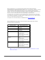
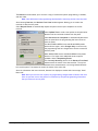
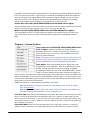
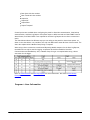
Before installing Remote Link, make sure that your computer hardware meets these minimum
specifications listed in the table below.
Operating System
Minimum Requirements
Windows 2000
Pentium 150 mHz
64 MB RAM
Windows XP
Pentium II 300 mHz
128 MB RAM
Windows Vista
1 GHz
1 GB RAM (32-bit)
16 GB hard disk space available
DirectX 9 Graphics
Windows 7
1 GHz
1 GB RAM (32-bit)
16 GB hard disk space available
DirectX 9 Graphics
Windows Server 2008 R2
1 GHz
1 GB RAM (32-bit)
16 GB hard disk space available
DirectX 9 Graphics
Note: You need to have Administrator Authority or select 'Run as Administrator' to install
Remote Link software.
© 2015 Digital Monitoring Products
You also need the following items:
800 x 600 or higher resolution monitor
CD-ROM drive
One available COM port if connecting to an SCS-1 or SCS-1R, SCS-105, or direct connecting to a
panel. Two available Com ports if using the pass-through feature.
Note: If using Remote Link on Windows 7 or Windows Vista under Standard Operator
authority, see Installing Link on Windows Vista or Windows 7.
Using a Virtual Environment:
Remote Link may be installed and used in a virtualized environment, provided that the virtual machine
is running an operating system listed in the Supported Operating Systems table. When running in a
virtualized environment, additional configuration of the virtual machine’s TCP and serial ports may be
required.
This section outlines specific steps to install and use Link on Windows Vista or Windows 7.
Operating System Privileges
The two types of Operating System user accounts referenced in this section are: administrator and
standard user accounts. These types of accounts have different privileges that allow or restrict the
functions a user can perform.
From the Windows 7 documentation: “Standard account users can use most software and change
system settings that do not affect other users or the security of the computer. Administrators have
complete access to the computer and can make any desired changes. Based on notification settings,
administrators may be asked to provide their password or confirmation before making changes that
affect other users.”
Link Operator Privileges
A Link operator is an individual that interacts with Link to perform a task. Operators may use Link
daily, or on an as-needed basis. However, all operators must log in to Link before most tasks can be
performed. Link allows privileges to be granted and/or removed to operator accounts. The privileges
are managed in the System > Operator Configuration screen. For the purposes of this document, it will
be assumed there are only two types of Link operators: administrators and standard operators. A Link
administrator has Administrator special permissions, a standard operator does not. See the Operator
Configuration section of the Link help for more information on operator privileges.
Roles
There are three roles discussed in this section. Note that an individual may serve more than one role
for an organization.
Workstation Administrator – has administrator access to the workstation operating system.
Link Administrator – has limited operating system privileges and administrator operator privileges
within the Link application. This also applies to Link Server administrators.
Link Operator – has limited operating system privileges and may also have limited Link operator
© 2015 Digital Monitoring Products
privileges.
The remainder of this document will assume a ‘typical’ organizational structure and Link
configuration. This is defined as:
There are one or more Workstation Administrators who perform maintenance of the
workstations. Workstation Administrators only interact with Link for installation, maintenance
and decommission.
There is at least one Link Administrator who performs operator management tasks within Link.
The Link Administrator interacts with Link on an as-needed basis.
There are one or more Link Operators who use Link on a daily basis. Link Operators cannot
perform Link installation, maintenance or management tasks.
Installing
A Workstation Administrator must perform installation of Remote Link, System Link or Link Server. A
Workstation Administrator must also perform any version upgrades to Remote Link and Link
Server. Any Link modules (e.g. Account Groups) should be activated at the time of installation by the
Workstation Administrator. See Registering and Activating Modules section of Link Help.
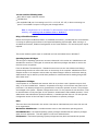
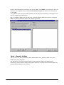
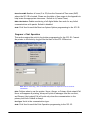
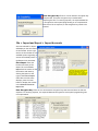
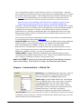
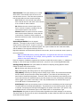
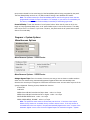
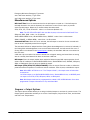
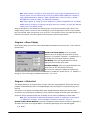
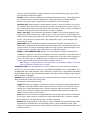
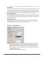
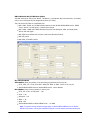
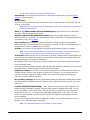
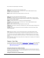
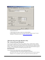
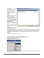
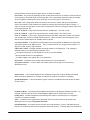
Registry Keys
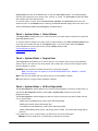
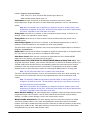
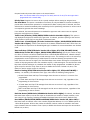
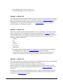
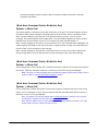
Once Remote Link and all modules are installed, the Workstation Administrator should give Link
Administrators Full Control access to modify the DMP key shown and its sub-keys.
A Link Operator does not require any additional registry privileges.
The primary registry key that Link uses to store application data is:
\HKEY_LOCAL_MACHINE\SOFTWARE\Digital Monitoring Products\
© 2015 Digital Monitoring Products
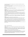
Registry Editor showing Link Registry Key
Database
This section discusses Database setup for Remote Link and System Link. For information on
configuring a Link Server database, refer to the Link Server section of this document.
If a Link Administrator is not a Workstation Administrator, then the Link database should not be
located in a system drive, such as C:\ or C:\Program Files. Locating the Link database in a non-system
directory will allow the Link Administrator to manage and move the database without requiring the
assistance of the Workstation Administrator.
The Workstation Administrator should grant Link Administrators and Link Operators full access to the
database folder (and subfolders) and the Link installation folder (and subfolders). This should be done
irrespective of the database location.
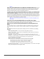
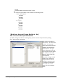
Link Server
This section discusses information specific to Link Server. Link Server allows multiple Remote Link
client workstations to use a single database. After Link Server is installed by a Workstation
Administrator, it may be used in day-to-day operation by a Link Operator.
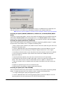
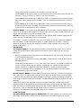
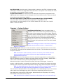
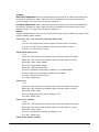
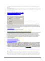
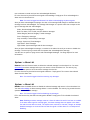
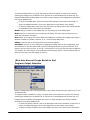
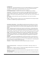
DBISAM Database Server
The primary component that differentiates Link Server from other Link installations is the DBISAM
Database Server, a SQL database service. Once Link Server is installed, the DBISAM Database Server
should start automatically when the workstation is started. A Workstation Administrator can start and
stop the service using the Services tool. A Link Operator should not be able to stop the service. All
Link Operator workstations that run Remote Link must be able to establish a TCP/IP connection to the
DBISAM Database Server address and port.
© 2015 Digital Monitoring Products
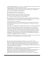
Link Server Database Service
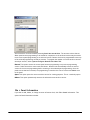
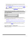
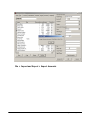
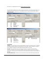
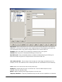
Remote Link offers an updated interface that is simple to navigate, and provides easy access to the
information you are most likely to need.
The Window menu allows you to switch between the windows you have open in Remote Link, or to
organize the way you view them. You may also switch between windows within Remote Link by holding
down the Ctrl and Tab buttons at the same time.
File > Close Panel will close the account file and all windows you currently have open.
File > Exit will close all windows you have open, disconnect you from a panel if you are connected, and
exit from Remote Link.
Clicking Apply applies all changes you have made in that window.
Clicking OK saves any changes you have made in that window and closes the window.
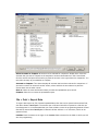
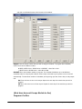
Your Remote Link database contains your subscriber account information, your password information,
and other valuable data. It is important to protect this information by performing regular backups of
the database.
Please backup your Remote Link database!
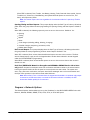
You can find the location of the Remote Link database by selecting System > Configure > Remote
Link to open the Remote Link Configuration window. Click on the Database tab near the top of the
window. The Database Location field will display the path to your database.
If you would like to store your Remote Link database in a different location than the default folder,
enter the location that you prefer for your Remote Link database in the Database Location field
before setting up any accounts.
© 2015 Digital Monitoring Products
Note: Do not attempt to move an existing database by changing the location listed in the
Database Location field. See instructions about creating a new database location.
If you change the location listed in the Database Location field without first moving the database
manually, you will receive a message asking, "Do you wish to create a new database?" If you click OK,
Remote Link creates a new database at the location that you just assigned and ignores the previous
database. This means you will not have access to any previous account information and
configurations settings from the previously existing Remote Link database.
Note: If you are using Remote Link on a computer connected to a network, run the Remote
Link program from your local hard drive, not from a network drive. Remote Link accesses the
database more quickly if the database is located on the local computer than if it is located on
a network drive. Only one computer at a time may use a Remote Link database.
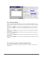
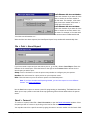
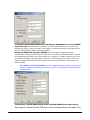
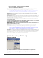
S ystem > L o g O N / O FF
Before using Remote Link, you must log in to the program with a user name and password. When you
open Remote Link, the Log On window automatically displays. You may log off and then log in as
another user any time the program is open.
The default log in is new for both your user name and password. Be sure the Caps Lock is not on.
Note: Keep track of your passwords and remember to always keep them in a safe location.
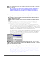
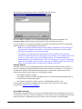
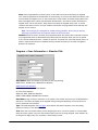
To configure Remote Link to directly connect to a panel, follow the steps below:
Select the desired panel in File > Panel Information.
In the Connection Information group box, select Direct from the drop-down menu in the Type field.
Select the COM Port to which the panel is connected.
Select the Baud Rate of the COM Port.
Note: You only need to complete these steps one time. On further connections simply select
the panel and then Connect as explained below.
After you have entered all the Connection Information, open the panel by clicking OK. Then go to
Panel > Connect and click the Connect button. You are now connected to the panel.
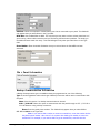
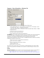
To configure Remote Link to connect to a panel through an SCS-1, SCS-1R, SCS-VR or SCS-105
Receiver using a dial-up connection, follow the steps below:
Select the desired panel in File > Panel Information.
In the Connection Information group box, select SCS-1 / SCS-105 from the drop-down menu in the
Type field.
Enter the Remote Key.
Enter the phone number of the panel.
Select Yes from the drop-down menu in the Dial field.
© 2015 Digital Monitoring Products
Note: You only need to complete these steps one time. On further connections simply select
the panel and then Connect as explained below.
After you have entered all the Connection Information, open the panel by clicking OK. Then go to
Panel > Connect and click the Connect button. You are now connected to the panel.
Using an XTL or XR150/XR350/XR550 panel
To configure Remote Link to connect to a panel through cellular communication, follow these steps:
1. Select the desired panel in File > Panel Information.
2. In the Connection Information box, select Cellular from the drop-down menu in the Type field.
3. In the Phone Number box, enter the phone number or SIM/MEID # for the cellular communication.
Select OK to apply these changes.
a. To retrieve the phone number or SIM/MEID #:
i. For SecureCom Wireless users, select System > SecureCom Wireless Activations. This shows
a list of all SecureCom activations. Right-click on the SIM/MEID # or phone number of the
panel to copy the number and then paste into the phone number box of the connection
information window.
ii. For non SecureCom SIM cards, enter the SIM phone number into the phone number box.
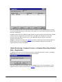
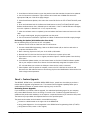
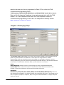
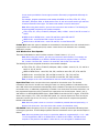
(A larm M o n ito rin g , Co m m an d Cen ter, o r A d van ced Rep o rtin g M o d u le)
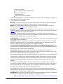
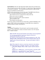
H elp > Reg istratio n
When you receive the module, you will also receive a manual and a certificate containing the serial
number that is needed for proper activation of the program. Once the program is installed on your
computer, enter the serial number in the Help > Registration window. Click the Add button and type
the module's serial number as listed on the certificate.
Note: You must right click on the Remote Link Icon and Run As Administrator before installing
any modules.
1. Go to Help > Registration.
2. Click Add.
3. In the field shown on the left, type the module's serial number as it appears on the certificate.
4. Click OK
© 2015 Digital Monitoring Products
5. A message box will appear reminding you to activate the module within 7 days.
Note: To ensure that the module is properly activated, do not lose the certificate or the serial
number. You have a 7-day grace period between the installation and the activation of the
module.
If you wish to continue registering and activating the module, follow the steps described in How to
Activate the Module.
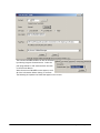
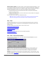
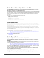
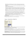
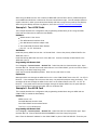
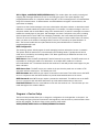
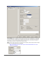
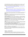
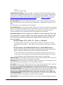
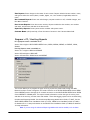
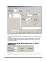
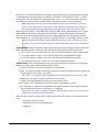
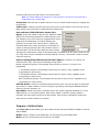
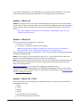
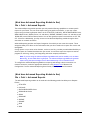
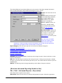
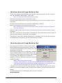
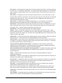
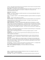
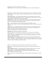
H elp > Reg istratio n
If you have purchased
additional Modules to
add-on to Remote
Link, you can enter
and view their serial
numbers under Help
> Registration. The
serial numbers must
be kept for proper
activation of the
modules. If you have
installed additional
Modules, enter the
serial numbers
immediately to
ensure a quick activation. Refer to Entering the Module's Serial Number and Activating the Module for
more information.
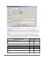
(A larm M o n ito rin g , Co m m an d Cen ter, A d van ced Rep o rtin g M o d u le,
A cco u n t G ro u p s an d S ecu reCo m W ireless)
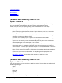
H elp > Reg istratio n
Within the 7-day grace period, call DMP's Customer Service at to activate the module. You can reach
DMP's Customer Service at (800) 641-4282 from 7 AM to 7 PM central standard time.
If activating the SecureCom Wireless service module, call Customer Service at 1-877-300-8030 for
activation.
When you are ready to activate the module open Help > Registration. If you do not see the module
listed, then the serial number has not been entered and the module has not been registered. To
register the module, click the Add button, enter the serial number listed on the certificate and click
OK.
© 2015 Digital Monitoring Products
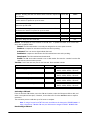
Select the module you wish to activate from the list of modules. Click the Activate button. Remote
Link will automatically generate a Public Key for the module. The serial number and Public Key will be
listed in a message box.
Call DMP Customer Service at (800) 641-4282 and have the serial number and the Public Key available.
Customer Service will generate an Activation Code. Click OK in the message box to enter the
Activation Code from DMP Customer Service. Click Activate. Now your Module is registered,
activated, and ready to use.
Change: To change the Account Level-upgrade the number of subscriber accounts allowed-select the
module from the list and click Change. You will then be prompted to follow the same steps as
registering and activating a new Module.
(A larm M o n ito rin g , Co m m an d Cen ter, o r A d van ced Rep o rtin g M o d u le)
H elp > Reg istratio n
To upgrade the Account Level (the maximum number of allowable subscriber accounts), open Help >
Registration after you receive the new CD-ROM and Certificate.
Select the module that you are upgrading and click Change. Enter the new Serial Number from the
upgrade Certificate. Follow the instructions to activate the module with the new level of accounts.
© 2015 Digital Monitoring Products
(A larm M o n ito rin g , Co m m an d Cen ter, o r A d van ced Rep o rtin g M o d u le)
H elp > Reg istratio n
If you decide to remove a module from your Remote Link program, follow the directions below.
Note: You need to have Administrator Authority to remove any modules from the program.
1. Click Help > Registration to open the Registration window.
2. Select the module that you wish to remove from the list in the Registration window. Click the
Remove button.
3. A pop-up window will appear asking if you are sure you want to remove the module. Click Yes if you
would like to remove the module.
4. You will then see a window that says, "Module Successfully Removed." Click OK.
5. Restart the program for the changes to take effect.
© 2015 Digital Monitoring Products
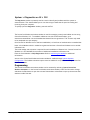
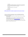
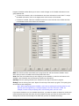
The SecureCom Wireless Activations window is used for managing control panel cellular service using
SecureCom Wireless, LLC. To establish cellular service with SecureCom Wireless, go to
www.securecomwireless.com and download the Network Service Agreement. This contract only needs
to be completed once per company.
Once SecureCom Wireless service has been established, a Certificate of Authentication is emailed that
bears a Serial Number which is needed to register and activate a SecureCom Wireless service module
in Remote Link.
The serial number and activation is required for each installation of Remote Link. Contact SecureCom
Wireless at 1-877-300-8050 for activation of additional installations of Remote Link.
Enter the Serial Number in Help>Registration. Refer to Activating the Module for additional
information.
Access to the SecureCom Wireless Activations window is enabled through System>Operator
Configuration. The Cellular Activations option must be enabled for an operator to manage SecureCom
Wireless SIM cards.
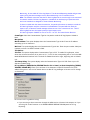
Programming
The SecureCom Wireless Activations window can be accessed by selecting System>SecureCom
Wireless Activations. In the SecureCom Wireless Activations window, select the SIM card to change
and select the Edit button to open the Activate SIM window or select New to open up the Activate SIM
window to add a SIM card.
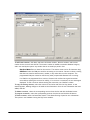
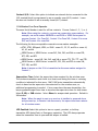
The Activate SIM/MEID window allows changes, activation, and deactivation of the selected SIM card.
Remote Link automatically populates the Rate Plan field with a suggested rate plan that most closely
matches the communication path programming for the panel.
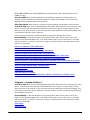
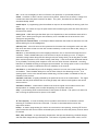
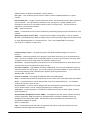
© 2015 Digital Monitoring Products
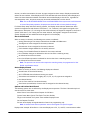
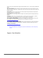
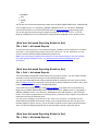
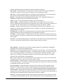
The Activate SIM/MEID window can also be accessed
by selecting Program>Communication. Select the
path programmed for Cell communication and click
on the Activate Button.
When the Activate SIM/MEID screen appears, enter
all of the information before clicking on Activate.
The following list explains the fields that appear on this screen:
© 2015 Digital Monitoring Products
Note: Complete all panel programming before activating the cellular path to ensure the correct
rate plan is calculated for usage.
SIM Type: Select the type of SIM card you are activating. Select either 200, 400, or MEID.
SIM/MEID Card#: Enter the SIM (Subscriber Identity Module) or MEID (Mobile Equipment Identifier)
number from the SecureCom AT&T Wireless SIM card, SecureCom T-Mobile Wireless SIM card, or the
263C/463C CDMA Cellular Communicator. The MEID number can be found on the label of the 263C or
463C.
Rate Plan: For XT Series, XTL, XR100, XR500 Series, and XR150/XR350/XR550 Series panels,
Remote Link automatically populates this field with a suggested rate plan that most closely matches
the communication path programming for the panel. If you choose to override the suggested rate plan,
you could experience overage fees from SecureCom Wireless, LLC.
Using Model 380-200 SIM Card
SIM Card
Data Included
Plan 203: Back-up alarm signal only
Level 200
0kb
Plan 205: Back-up or primary alarm signal only, provides for weekly
test
Level 200
50kb
SIM Card
Data Included
Plan 406: Back-up or primary path with a daily test
Level 400
50kb
Plan 408: Primary path with hourly check-in and O/C reports for up
to 4 areas.
Level 400
200kb
Plan 410: Primary path with an hourly test and O/C reports for up to
8 areas.
Level 400
300kb
Using Model 380-400 or 380-400T SIM Card
© 2015 Digital Monitoring Products
Plan 416: Primary path with a 6 minute check-in and O/C reports for
up to 8 areas.
Level 400
1000kb
Plan 425: Primary path provides for 3 minute check-in OR 4 minute
check-in with O/C reports for up to 16 areas.
Level 400
2000kb
Plan 435: Dual primary paths provide for 6 minute check-in and O/C
reports for up to 8 areas.
Level 400
3000kb
Plan 445: Dual primary paths provide for 3 minute check-in OR 4
minute check-in with O/C reports for up to 16 areas.
Level 400
4000kb
XT: Daily test with a flat rate.
Level 400
N/A
XTL: Daily test with a flat rate.
Level 400
N/A
CellComSL: Daily test with a flat rate.
Level 400
N/A
Status: This displays the current status of the SIM card. To update the status of the current SIM
card, click on Update Status.
Unused: The SIM card number is currently not assigned to an active panel account.
Pend Act: A request for activation has been sent and is pending.
Activated: This is an active digital cellular SIM card.
Pend DeAct: A request to deactivate this SIM card has been sent and is pending.
Deactivated: This SIM card has been deactivated.
Invalid: The SIM card number entered is not a valid number. Re-enter the number from the SIM
card and retry the activation process.
Text Plan: Select the rate text plan for the SIM card. Plans available include:
Text Plans Available:
SIM Card
Available Panels:
None: Messaging is not included
Level 400
XT30, XT50, XTL, XR100, XR500,
XR150, XR350, XR550, CellComSL
SMS100: 100 Messages per month
Level 400
XT30, XT50, XTL, XR100, XR500,
XR150, XR350, XR550, CellComSL
SMS200: 200 Messages per month
Level 400
XT30, XT50, XTL, XR100, XR500,
XR150, XR350, XR550, CellComSL
MyAccess: Unlimited messages
Level 400
XT30, XT50, XTL, XR100, XR500,
XR150, XR350, XR550, CellComSL
Activating a SIM card
From the Activate SIM window, enter the SIM card number, select the SIM type as 200 or 400, and
select a rate plan and text plan, if desired, for this SIM card. Click the Activate button to request
activation.
The activation process could take up to 24 hours to complete.
Note: If using a SecureCom AT&T SIM card, the APN must be changed to SECURECOM400. If
using a SecureCom T-Mobile SIM card, the APN must be changed to GRID.T-MOBILE.COM.
Deactivating a SIM card
© 2015 Digital Monitoring Products
From the Activate SIM or SecureCom Wireless window, click the Deactivate button to request
deactivation.
© 2015 Digital Monitoring Products
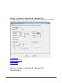
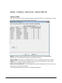
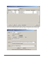
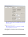
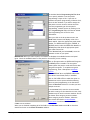
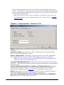
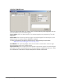
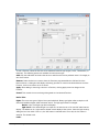
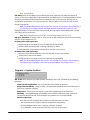
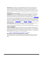
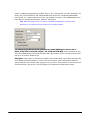
S ystem > Co n fig u re > Rem o te L in k > Receiver Tab
The programming options in the Remote Link Configuration window are available on the following
tabs: Receiver, Modem, Database, Other, Network, Modules, and Custom Fields.
Current Receiver
Receiver General Options
Receiver Lengths
Default Receiver
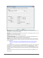
S ystem > Co n fig u re > Rem o te L in k > Receiver Tab
Current Receiver
© 2015 Digital Monitoring Products
Model: Select the receiver from the drop-down menu to configure.
© 2015 Digital Monitoring Products
S ystem > Co n fig u re > Rem o te L in k > Receiver Tab
Communications Options
COM Port: Select the communications port connected to the receiver from the drop-down menu. The
SCS-1R can be configured when using the SCS-150 Processor Board.
Be careful to select a setting that does not interfere with your mouse, modem, or any other device on
your computer. The COM port cannot be used for any other purpose while Remote Link is running.
Baud rate: Set your baud rate to the same setting as your receiver. The default setting is 9600 baud.
If you are using an SCS-1 Receiver Version 812 or SCS-1R to access your alarm panels, you may set
your baud rate to 19200. The baud rate set here must also be set in the SCS-1 Receiver. See LT-0065
for more information about configuring the SCS-1 Receiver or LT-0717 for the SCS-1R Receiver. If you
are using an SCS-105 or SCS-1R/SCS-150 Receiver to access your alarm panels, set your baud rate to
9600.
Dial Out Line #: This number refers to which line card that your current receiver will use to dial out.
SCS-1 or SCS-1R (using SCS-1062): Select 1-5
SCS-1R/150 (using SCS-150): Select 1-8
SCS-105: Set this value to 1.
Tone Dial: Check this box if you wish to tone dial. Leave this box empty for pulse dial.
Note: The SCS-1 or SCS-1R will always pulse dial, regardless of this setting.
© 2015 Digital Monitoring Products
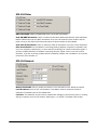
Syste m > C onfigure > R e m ote Link > R e ce ive r T a b
General Options
Areas: Select which reporting format Remote Link will use to communicate with panels.
Bin: 2-character hexadecimal mode. Use this mode with SCS-105 Receivers.
Dec: 2-character decimal mode. Select this mode if the SCS-1 or SCS-1R Receiver has been
programmed to require Dec mode.
Start Character: When the SCS-1 or SCS-1R Receiver has a line configured to attach to a data
network, set the Start Character to the same as the character programmed in the SCS-1 LSU Host
Configuration. The default setting is STX. Refer to your SCS-1 Receiver Installation and User's Guide
(LT-0065) or SCS-1R Receiver Installation Guide (LT-0717).
None: Use this option when the SCS-1 or SCS-1R Receiver is not connected to a data network.
STX: Use this option when the SCS-1 or SCS-1R Receiver is configured to use STX.
Other: If the SCS-1 or SCS-1R Receiver is set to a different Start Character than the available
options, select Other and enter that Start Character in the field immediately to the right of the
Start Character menu.
CRC: Check this box if the SCS-1 or SCS-1R Receiver CRC option in the LSU Host Options is set to
YES.
Sequence Numbers: Check this box if the Sequence Numbers option in the SCS-1 or SCS-1R Receiver
LSU Host Setup is set to YES.
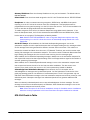
Syste m > C onfigure > R e m ote Link > R e ce ive r T a b
Receiver Lengths
Line #: This field designates how many digits the receiver will use for the line number used by the
panel to communicate a message.
CS-1 or SCS-1R Receivers: Select 1 to allow single-digit numbers or 2 to allow two-digit line
numbers. Select 0 to allow no line numbers.
SCS-105 Receivers: Always select 0 for SCS-105 Single Line Receivers.
Zone #: This field determines how many digits may be assigned to report a zone number. This
© 2015 Digital Monitoring Products
number should correlate with the number of digits of the zones that report to the panel.
For example, the XR200 panel has zones 1 through 299. So you would want to set this to 3 to allow all
299 zones to report.
SCS-1 or SCS-1R Receivers: This number must match the zone number programmed in the
Host setup programming on the receiver.
CS-105 Receivers: Use 3 for SCS-105 Single Line Receivers.
User #: Select the number of digits used to report a user number. Select 3 to allow 999 users.
SCS-1 or SCS-1R Receivers: This number must match the User number programmed in the
Host setup programming on the receiver.
SCS-105 Receivers: Use 3 for SCS-105 Single Line Receivers.
(M u st h ave an ad d itio n al m o d u le to U se)
S ystem > Co n fig u re > Rem o te L in k > Receiver Tab
The Default Receiver field allows you to assign a receiver number for Host/Net Monitoring. Enter a
number from 1 to 9 that represents Host/Net Monitoring. This is to help you distinguish between
alarms received in the Host mode and those received from another type of receiver, such as an SCS-1
or SCS-1R Receiver.
If you do not enter a number in this field, the receiver number for host monitored accounts will default
to 1 (one).
© 2015 Digital Monitoring Products
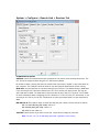
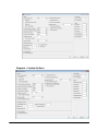
Syste m > C onfigure > R e m ote Link > M ode m T a b
Use the Modem tab to configure Remote Link when connecting to a DMP 462FM 9600 Baud Modem
installed on a panel or when connecting to an XR500 Series or XR2500F for programming the panel at
2400 baud through the panel dialer. This allows you to connect to the panel using a standard computer
modem.
S ystem > Co n fig u re > Rem o te L in k > M o d em Tab
Communication Options
COM Port: Select the COM port that is connected to your modem. Use the Modem tab to configure
Remote Link to connect to a panel that has a DMP Fast Modem installed or when connecting to an
XR500 Series or XR150/XR350/XR550 Series panel for programming at 2400 baud through the panel
© 2015 Digital Monitoring Products
dialer. This allows you to connect to the panel with a standard computer modem.
Note: These are for the local computer modem.
Baud Rate: Set the baud rate for Remote Link to communicate with the computer modem. Default
setting is 9600.
Flow Control: Select the flow control option recommended by your modem manufacturer. The default
setting is Hardware. If the modem does not operate correctly with the default Hardware setting, select
ON/OFF, also known as software flow control. If neither setting operates correctly, select None. For
more information see your modem documentation.
Tone Dial: Check this box if you wish to tone dial. Leave this box empty for pulse dial.
Syste m > C onfigure > R e m ote Link > M ode m T a b
General Options
Dial Time Out: Enter the length of time Remote Link will wait for the XR500 Series or XR150/XR350/
XR550 Series panel or 462FM to pick up. Enter a range from 1 to 255 seconds. The default is 60
seconds. You may need to extend the Dial Time Out depending on the 462FM's programmed Ring
Count. Extend the Dial Time Out about 10 seconds for each ring programmed in the Ring Count.
Modem Initialization String: If an initialization string is required for the modem communicating to
the panel, enter the setup string here. The string can be up to 32 characters long.
Special Initialization String: The special initialization string required to ensure the modem
communicates consistently at a slower baud rate is entered here. The string can be up to 32
characters long.
Note: Only one initialization string can be used. Select the correct one for your operation. See
Panel Information.
© 2015 Digital Monitoring Products
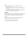
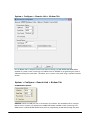
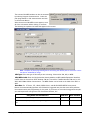
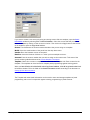
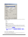
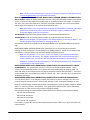
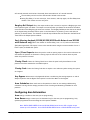
S ystem > Co n fig u re > Rem o te L in k > D atab ase Tab
The settings in the Database tab allow you to change the location where Remote Link stores data on
your computer's hard drive. It also allows you to backup and purge your Remote Link database, as well
as merge another Remote Link database into the existing or import your Remote Access database into
Remote Link.
Note: Before performing any database maintenance function, it is recommended that you
backup the Remote Link database folder to prevent the possible loss of valuable data.
You may move your Remote Link database to a folder on your computer hard drive, or to any
connected network drive.
© 2015 Digital Monitoring Products
S ystem > Co n fig u re > Rem o te L in k > D atab ase Tab
General Options
Database Location
Computer Hard Drive: Enter the path to the Remote Link database location on the computer or
network hard drive. If you would like to store your Remote Link database in a different location than
the default folder, type the location in the Database Location field. You may also browse for the folder
where you would like to place your Remote Link database by clicking on the button just to the right of
the Database Location field with three small dots.
The database may also be stored on a remote network server. This option allows more than three
Remote Link computers to perform extensive database operations at the same time. Refer to the Link
Server Installation Sheet (LT-0837).
Network Server: To use Remote Link with Link Server, enter the network server IP address and port
number to the Remote Link database location. The default port number is 12005. Check with your Link
Server administrator for the correct IP address and port number and enter the information using the
following format:
server: xxx.xxx.xxx.xxx:ppppp
x = IP Address
p = Port Number
Note: Standard Remote Link operation supports database access for up to three computers as
long as only one computer at a time performs extensive database access operations such as
uploading or downloading information from a panel. If more computers or more extensive
simultaneous database access is required, it is recommended the Link Server software be
installed on a network server.
Database Relocation: To manually move your Remote Link database, use Windows Explorer and copy
the complete database folder (usually "C:\Link\Db") and paste to the desired location. Go to the
Database Location field and either type the new location of the database into the field or click the
browse button to locate where you have relocated the database.
If you change the location listed in the Database Location field without first moving the database
manually, Remote Link displays a message asking, "Do you wish to create a new database?" If you click
on OK, Remote Link creates a new database at the location that you just assigned and ignores the
previous database. This means that Remote Link does not have access to any previous account
information and configurations settings from the previously existing Remote Access database.
Note: If you are using Windows 2000 or XP, only users with administrative privileges in
Windows can relocate the database. If a user without administrative privileges attempts to
move the database, Remote Link does not save the attempted relocation.
If Remote Link does not start up correctly, one cause could be an invalid database location. Use the
command line option "/dblocation" to set the path to the database. Go to Start > Run and type c:\Link
\Link.exe /dblocation LOCATION.
© 2015 Digital Monitoring Products
In place of LOCATION, type:
"c:\database path\" for a local or shared file server database
server:192.168.0.111.12005 for a server based database
where 192.168.0.111 is the IP Address where the server database is located
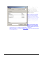
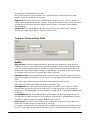
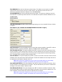
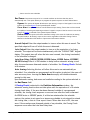
S ystem > Co n fig u re > Rem o te L in k > D atab ase Tab > B acku p O p tio n s
As a safety measure, it is always wise to create a backup of your database. Remote Link provides you
with the option to backup your database on a regular basis. A reminder will appear to remind you to
backup your database.
Click on the Options button to open the Backup Options window.
Note: When using Link with SQL Server, all backup and repair operations must be performed
by the database administrator, using SQL Server management tools. Remote Link does not
perform these operations.
Backup Location: Enter the location where you want the Backup Database to reside. For example, C:
\Backup tells Remote Link to place the Backup database in the Backup folder on the C drive of your
computer.
You may also browse for the folder where you would like to place your Remote Link Backup Database.
To browse for the location where you wish to place the database, click on the button with three small
dots just to the right of the Database Location field.
When the database resides on a network server, check with your System Administrator. The backup
function cannot be performed for a database that resides on a server.
You may choose to have Remote Link remind you when it is time to backup your database. Click the
"Remind me to backup after" checkbox. Then enter the number of days you would like between
backup reminders.
Click OK when finished entering in all of the fields. You may also click Backup to run the backup
immediately or at any time to run a non-scheduled backup.
When it is time for a scheduled backup, a pop-up window will appear when it is time to backup the
database. If you select Yes the pop-up window closes and opens the Backup Options dialog box. Click
the Backup button to perform the scheduled Backup.
If you select No, another pop-up window will appear the next time you log on to Remote Link.
Note: Only the System Administrator can backup the Remote Link Database. If an operator
with a authority level lower is logged on when a backup reminder message is displayed, the
operator is prompted to contact the System Administrator.
© 2015 Digital Monitoring Products
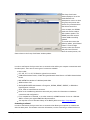
S ystem > Co n fig u re > Rem o te L in k > D atab ase Tab > M erg e
Merge allows you to combine another Remote Link database with an existing database.
Note: The Merge option is not available if using Remote Link with the SQL Server module.
Go to System > Configure > Remote Link to open the Remote Link Configuration window. Click on
the Database tab and then click the Merge button to open the Merge Database window.
In the Merge Database window, enter the path to another Remote Link database to merge with the
existing database. You may also browse to the location of another Remote Link database by clicking
on the button just to the right with three small dots. All of the accounts from the chosen database are
copied and merged into the existing database.
Note: Only a database located on a local or network drive can be merged. A database located
on a remote server cannot be merged.
© 2015 Digital Monitoring Products
Note: If an account being merged has the same receiver and account number as one in the
existing Remote Link database, an error message displays and the account is not merged.
After following the instructions above, click Merge to complete the merge operation.
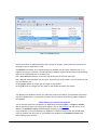
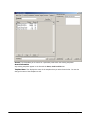
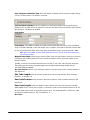
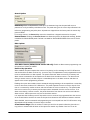
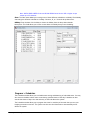
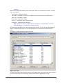
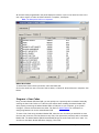
S ystem > Co n fig u re > Rem o te L in k > D atab ase Tab > Pu rg e O p tio n s
Purge allows you to remove Remote Link activity from the database. Select the start and end dates,
then select Activity or Events.
When the database resides on a remote network server, check with your System Administrator. The
Purge operation cannot be performed for a database that resides on a remote network server.
© 2015 Digital Monitoring Products
Start Date: Enter the first date that you would like to purge events. You may type the numbers, use
the arrow keys, or use the drop-down calendar.
End Date: Enter the last date that you would like to purge events. You may type the numbers, use the
arrow keys, or use the drop-down calendar.
Activity: Select Activity to remove the Remote Link activity.
Acknowledged Messages: Select Acknowledged Messages to remove all acknowledged Alarm List
messages. You can still print these messages after you have purged them.
Events: (Must have an additional module to use) Selecting Events purges events such as all alarms,
troubles, opening/closing events, and door access events. After these events are purged, you cannot
print these reports.
Note: You may purge Activity, Acknowledged Messages, and Events by selecting all three
checkboxes. If no checkbox is selected, Remote Link will not remove anything from its
database.
If needed for reference, print the Activity, Acknowledged Messages, or Events lists prior to performing
the purge process. If the related window is open with Activity, Acknowledged Messages, or Events
displaying prior to starting the purge process, the list of Activity, Acknowledged Messages, or Events
continue to display. Close and then reopen the specific List window to remove the purged items from
the display.
Click the Purge button to remove all activity and/or events from the Remote Link database for the
selected dates.
© 2015 Digital Monitoring Products
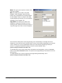
The Restore from Backup window automatically appears if your database is corrupt and you need to
restore it.
Note: To restore from a backup, you must have a backup file already made. Be sure to backup
your Remote Link database frequently.
Note: When using Link with SQL Server, all backup and repair operations must be performed
by the database administrator, using SQL Server management tools. Remote Link does not
perform these operations.
Restore from File: Enter the file from which you wish to restore. Press the button to the right of the
field to browse for the most recent backup file.
Restore Location: Enter the location in which you want the backup to be restored.
Note: The Restore Location will typically be where your Remote Link database currently
resides.
Press the Restore button to restore your database from the selected backup file.
Note: If the Restore from Backup window does not automatically open, close Remote Link and
follow the directions below.
Go to Start > Programs > Remote Link.
Click on Restore Database.
It is possible your Remote Link account database may be damaged if your computer experiences a
power outage or a hardware or software problem that causes Remote Link to stop unexpectedly. The
Repair feature attempts to repair corrupted account information, activity, panel programming, and
configuration files in your Remote Link database. If you believe your Remote Link database is
damaged or corrupt, close Remote Link and follow the directions below.
Go to Start > Programs > Remote Link.
Click on Repair Database.
You will then see an information window listing off the database files that are being repaired. When
the database is repaired, the Log On / Off window will open.
Note: When using Link with SQL Server, all backup and repair operations must be performed
by the database administrator, using SQL Server management tools. Remote Link does not
perform these operations.
© 2015 Digital Monitoring Products
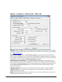
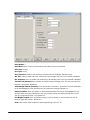
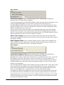
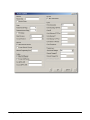
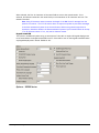
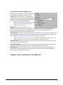
S ystem > Co n fig u re > Rem o te L in k > O th er Tab
Time Zone: Under the Other tab, select the appropriate time zone where your Remote Link computer
is located from the drop-down menu. If your time zone is not listed, enter a time zone value according
to the table of time zones.
Enable Debug Logging: Select the Enable Debug Logging to allow all communication between the
panel, receiver, and Remote Link to be saved in the debug table for diagnostic purposes. Uncheck the
box to disable this function. When the box is unchecked, you will not be able to view communication in
the diagnostics screen. By default, Enable Debug Logging is selected.
Enable Alarm/Event Monitoring: Select Enable Alarm/Event Monitoring to allow Remote Link to
display panel alarms and system event messages in the Alarm List. Uncheck this option when Remote
Link is used for programming purposes with a shared database without displaying panel messages. By
default, Enable Alarm/Event Monitoring is checked and should be checked when using the Alarm/
Event Monitoring mode.
Logging Threshold: Select the type of issue to log into the Remote Link error log file. By default,
Logging Threshold is set to Warning. All messages with a severity equal to or greater than the
threshold setting will be logged.
Debug: Detailed information that does not indicate an error, similar to communication strings. This
setting greatly increases the size of the log file.
© 2015 Digital Monitoring Products
Information: General information detail about program operations.
Warning: An error condition such as minor communication problems, timeouts, etc. that can be
handled without operator intervention. A warning message may or may not be displayed to the
operator.
Exception: An error that requires operator action to recover or restore normal operation such as an
invalid COM Port selection for the receiver.
Critical: An error that caused Remote Link to stop responding such as an Access Violation or database
corruption.
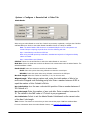
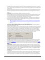
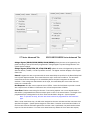
A rchive
Pass T hrough Options
A dm in Reader
Enable Auto Account Archive: Select this option to allow panel
account programming to be automatically archived (saved
separately) when connecting to a panel with programming different
than the programming currently on file. Default is unchecked.
To archive panel account programming manually, select File>Panel
Information.
Max Per Account: Select the maximum number of panel programming archive verisons allowed to be
stored per account. Allowed range is 1 to 20 archives. Default is 5.
S ystem > Co n fig u re > Rem o te L in k > O th er Tab
Pass Through Options
Mode: When Remote Link is in the Pass Through mode, standard panel reports will be sent to and
acknowledged from a host computer. Select the appropriate setting.
None: Select this option if you are not using Pass Through mode to relay signals to automation
software.
Pass Through: Select this option to pass reports through the Remote Link computer to a host
automation computer.
Outgoing COM Port: Select the COM port that Remote Link will use to communicate with your host
automation computer.
Baud Rate: Set the baud rate to 9600 unless your automation software requires a different setting.
© 2015 Digital Monitoring Products
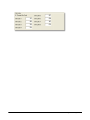
Syste m > C onfigure > R e m ote Link > Othe r T a b
Admin Reader
When using an Admin Reader to enter User Codes from proximity credentials, configure the COM Port
and Baud Rate here. Refer to the Admin Reader Installation Sheet (LT-0619) as needed.
Note: The Admin Reader USB connects to a standard USB port on a PC and operates as a
virtual COM port requiring a special driver from the following web site.
http://www.ftdichip.com/Drivers/VCP.htm
When using non-DMP proximity credentials, download and adjust the Configuration Utility
values as needed.
http://www.rfideas.com/Software/
COM Port: Select the virtual COM Port to which the Admin Reader is connected.
Baud Rate: Select the baud rate at which the Remote Link communicates with the Admin Reader. The
default Baud Rate is 9600.
Reader Model: Select the connection used for the Admin Reader.
Serial: Select this option when using a Reader connected to a serial port.
USB 6081: Select this option when using a Reader connected to the USB port.
Max Code Length: Select the number of characters, 5-10, for the user code.
When using a custom card, enter the total number of bits to be
received in Wiegand code including parity bits. Enter a number between 0-255 to
equal the number of bits. Default is 26 bits.
Wiegand Length:
User Code Position: Enter
the user code start bit position. Enter a number between 0-
255. Default is 9.
Enter the number of user code bits. Enter a number between 1632. The default is the DMP value of 17 which is pre-programmed.
User Code Length:
Select to set the Admin Reader fields based on the current value
of the Max Code Length.
Set Card Defaults:
Test: Click the Test button to ensure that you have entered the proper COM Port and Baud Rate.
For more information about the Admin Reader feature, see Scanning a Proximity Card.
© 2015 Digital Monitoring Products
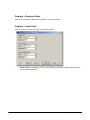
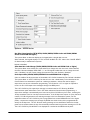
S ystem > Co n fig u re > Rem o te L in k > N etw o rk Tab
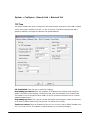
TCP Trap
The options available are used to configure the TCP communication connection to the iCOM or iCOM-E
version 103 or higher installed in the SCS-1 or SCS-1R receiver. This allows network panels with a
dynamic IP address to be trapped for Remote Link upload/download.
TCP Trap Enabled: Check this box to enable TCP Trapping.
Programming App. Address: Enter the IP address of the Remote Link computer used to program
panels. If the Remote Link computer is behind a firewall, enter the IP address of the network router.
This address is sent to the panel iCOM or iCOM-E to use for connection to Remote Link for a remote
upload/download session.
Programming App. Port: This is the port used by the Remote Link computer to make the connection
to the panel, iCOM and iCOM-E using TCP protocol. The default value is 2002.
Trap Server Address: Enter the IP address of the SCS-101, SCS-104, iCOM or iCOM-E installed in the
SCS-1 or SCS-1R receiver. This address is used by Remote Link to send trap messages.
© 2015 Digital Monitoring Products
Trap Server Port: This is the port used by Remote Link to communicate with the SCS-101, SCS-104,
iCOM or iCOM-E installed in the SCS-1 or SCS-1R.
Auto Send Traps: This enables Remote Link to resend the trap command continuously to the SCS-1R
receive. This prevents the receiver from discarding the trap after a four-hour period. The trap is
resent based on the number of seconds programmed into the Auto Send Delay. Default is disabled.
Auto Send Delay: If Auto Send Traps is enabled, enter the number of seconds that Remote Link
waits between resetting traps. Default is 180 seconds. Minimum is 30 seconds.
Customer: Choose a customer from the drop-down list. Traps will be sent only to the accounts of the
customer selected.
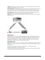
S O CK S Pro xy
A SOCKS proxy server is a server-based computer application used to transfer data between client
computers using a set of filtering rules for enhanced security. SOCKS is an abbreviation for "sockets,"
which are connection points on the Internet. The SOCKS Internet protocol serves to keep client
machines safe and anonymous for security purposes and to help speed up the access of routinely
accessed data, especially when used in conjunction with a firewall.
How SOCKS works
SOCKS works as a client/server. A users’ workstation must have a SOCKS client installed, either in the
application (such as putty, Firefox), or in the TCP/IP where the client software redirects packets into
a SOCKS tunnel.
The SOCKS client will initiate a connection to a SOCKS server. The SOCKS protocol allows
authentication and logging of the connection requests.
The SOCKS server then acts as the IP Client for the connection request. This means that the external
server is only aware of the SOCKS Server (the proxy).
© 2015 Digital Monitoring Products
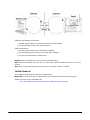
SOCKS has the following key features:
provides authentication for protocols that cannot be authenticated
by passes default routing in the internal network
SOCKS requirements:
the client program must have a SOCKS client capability
the client operating system must have SOCKS client capability
you must run and maintain a SOCKS server
Version: Select the SOCKS Proxy version from the pull down menu.
Host: Enter the IP address of the SCS-101, SCS-104, iCOM or iCOM-E installed in the SCS-1 or SCS-1R
receiver.
Port: Enter the port through which you will connect to the panel. number 1 to 65535.
Cellu lar N etw o rk
This enables a cellular backup connection for Remote Link.
Direct Cell: Click the check box to enable. Remote Link communicates with the panel through a
cellular connection using a SIM/MEID card.
Note: See Backup Connection Information for additional setup information.
© 2015 Digital Monitoring Products
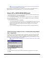
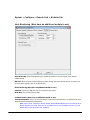
S ystem > Co n fig u re > Rem o te L in k > M o d u les Tab
H o st M o n ito rin g (M u st h ave an ad d itio n al m o d u le to u se)
Host Monitoring: Select Host Monitoring to enable the module to receive signals from network
enabled panels.
UDP Port: Enter the data network UDP port number through which the module will use to monitor for
incoming alarm signals. 2001 is the default port.
Direct Monitoring (Must have an additional module to use)
COM Port: Select the COM port that is connected to your panel.
Baud Rate: Set the baud rate to 9600.
Command Center (Must have an additional module to use)
Track Armed Status: Select Track Armed Status to allow the Command Center to display the armed/
disarmed status of all monitored accounts.
Note: All XT Series, CellComSL, XR100, XR500, XR150/XR350/XR550 Series can track the Arm/
Disarm status of the panel, however, for the XR200 Series, only the XR200 (version 110) and
XR200-485 (version 204) have this capability.
© 2015 Digital Monitoring Products
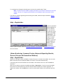
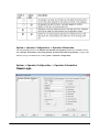
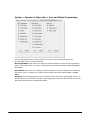
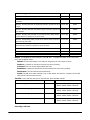
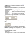
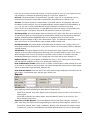
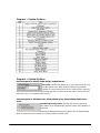
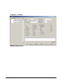
S ystem > Co n fig u re > Rem o te L in k > Cu sto m Field s Tab
Cu sto m Field s
The Custom Fields tab is used to rename field titles and maintain selections in drop down lists located
on the Panel Information screen and the User Codes screen.
Edit List: The Edit List button allows the list of acceptable selections to be maintained by an
Administrator. Select the field to change and click the Edit List button.
Table and Field: These indicate the database location. These are preloaded and cannot be edited.
Caption: This is the field title that is displayed on the Panel Information and User Codes screens.
Double-click in the Caption column to change the title.
Limit To List and Admin Add: These two settings work together to determine how entries, that use a
drop down list of items, will be handled.
The following table describes the effect of the possible combinations:
© 2015 Digital Monitoring Products
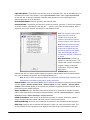
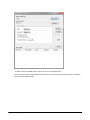
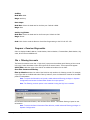
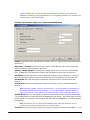
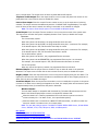
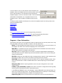
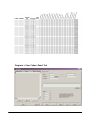
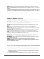
Syste m > Ope ra tor C onfigura tion > Ope ra tor Inform a tion
The programming options in the Remote Link Operator Configuration window are available on three
tabs, Operator Information, Panel Programming, and User and Status Programming. To give users
authority to log in to Remote Link, select System > Operator Configuration.
S ystem > O p erato r Co n fig u ratio n > O p erato r In fo rm atio n
Classic Login
© 2015 Digital Monitoring Products
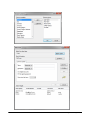
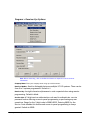
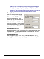
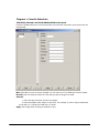
Login Information: To authorize a new operator to log in to Remote Link, click on the New button at
the bottom left corner of the window. In the Login Information fields, enter a Login and Password
for the new user. At Re-enter Password retype the same password to verify. Each login ID and
password may have up to 32 characters.
Personal Information: Enter the operator's last and first name.
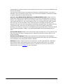
Account Access: To authorize the operator to access all accounts, select All. To restrict the operator
to certain accounts, select Restrict and click the . . . button. In the Select Accounts window, place a
checkmark next to the accounts the operator is authorized to access.
Note: The Account Access restrict
option does not prevent an
operator from using the trap
function to send and/or retrieve
changes made by other operators.
Note: When the Account Groups
module is enabled, the Account
Access restrict option does not
prevent an operator from adding
users and the display only lists
accounts the operator is authorized
to access.
User Restrictions: To limit the
operator to view only access. This
operator will not have the ability to
program, change or add panel
information. Click on the View
Only option.
Administrator: Check the
Administrator box to provide complete authority to perform administrative functions within Remote
Link, such as adding new operators and configuring Remote Link.
Note: Be sure at least one operator always has Administrator level authority. Only users with
Administrator level authority may add or modify authorities.
Remote Update: Check the Remote Update box to authorize the operator to perform remote updates
from the System > Remote Update, Panel > Remote Update, or Trap > Options > Remote Update
windows. When Remote Update is not checked, the windows are grayed out and the operator cannot
perform the remote update operation.
Import and Export: Check the Allow Import and/or Export box to authorize the operator to import
and/or export panel account information and programming. See File > Import and Export > Import
Accounts or File > Import and Export > Export Accounts.
Cellular Activations: Check the box to authorize the operator to activate, deactivate, update or
assign SecureCom Wireless cellular SIM cards to active control panel accounts.
Advanced Filtering: Check the box to authorize the operator to use the advanced filtering option.
Allow Trap: Check the box to authorize the operator to create, set, send, and retrieve traps. This
must be enabled for the trap options in the Remote Link Panel menu to be accessible to the user.
© 2015 Digital Monitoring Products
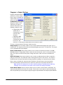
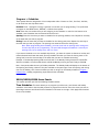
Single Sign-On
Single Sign-On allows a Remote Link operator to be associated with their Windows user account. When
launched, Remote Link matches the Windows user currently logged in to an operator in the Remote
Link database. This feature eliminates the need for Central Station operators to remember a Remote
Link password and allows improved control of access to Remote Link. If a Windows user account fails
to match a Remote Link operator an Application Access Denied dialog box displays and the user is
denied access to Remote Link.
Remote Link will default to using Classic Login when upgrading software from previous versions that
did not support Single Sign-On or when creating new databases.
Note: Administrator level authority is required to add Single Sign-On users or modify
authorities.
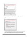
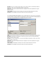
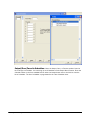
To Enable Single Sign-On:
From the main Remote Link screen, select System > Operator Information to display the Operator
Configuration window. Click the Authentication… button at the bottom center of the screen. The
Operator Authentication Method dialog displays detailing the two types of operator authentication.
Click Next to continue or click the Cancel button to terminate the process.
© 2015 Digital Monitoring Products
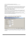
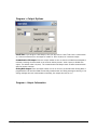
The Select Authentication Method dialog box displays with Classic Login and Single Sign-On
checkboxes. Select Single Sign-On and click Next to continue or click Cancel button to terminate the
process.
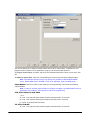
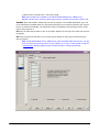
The Single Sign-On dialog box displays with the Remote Link administrator account and the Windows
user account to be mapped. Click Finish to complete authorization. The Back button will return you to
the Select Authentication Method screen or click the Cancel button to terminate the process.
© 2015 Digital Monitoring Products
Once enabled, the Login, Password and Re-enter Password controls on the Operator Configuration
screen in Remote Link are replaced with Single Sign-On Information containing:
Windows User Account
Operator's Name (User Name)
Single Sign-On Information
Click the Edit button to display the Windows Select User window. From the Select User window you may
select:
Object Types
Locations
Check Names
© 2015 Digital Monitoring Products
Object Types
The Windows User Object Type is automatically displayed.
Locations
Click the Locations button to select the location of the Windows user account. You may select the local
computer or a Windows directory of users on the network. When the local computer is selected, access
is limited to the selected computer. If the same operator logs in to a different computer, access will
be denied.
© 2015 Digital Monitoring Products
Check Names
Enter a user name in the field and click the Check Names button to search the directories for matching
user names.
Advanced
Click the Advanced button to display the expanded search feature.
© 2015 Digital Monitoring Products
To add or remove available search criteria, click on the Columns button.
Once the desired search columns have been selected, you may enter key words and other information
in the Common Queries fields.
© 2015 Digital Monitoring Products
© 2015 Digital Monitoring Products
Additional Information
Personal Information: Enter the operator's last and first name.
Account Access: To authorize the operator to access all accounts, select All. To restrict the operator
to certain accounts, select Restrict and click the . . . button. In the Select Accounts window, place a
checkmark next to the accounts the operator is authorized to access.
© 2015 Digital Monitoring Products
Note: The Account Access restrict
option does not prevent an operator
from using the trap function to send
and/or retrieve changes made by
other operators.
Note: When the Account Groups
module is enabled, the Account Access
restrict option does not prevent an
operator from adding users and the
display only lists accounts the
operator is authorized to access.
User Restrictions: To limit the
operator to view only access. This
operator will not have the ability to
program, change or add panel
information. Click on the View Only
option.
Administrator: Check the
Administrator box to provide
complete authority to perform
administrative functions within
Remote Link, such as adding new operators and configuring Remote Link.
Note: Be sure at least one operator always has Administrator level authority. Only users with
Administrator level authority may add or modify authorities.
Remote Update: Check the Remote Update box to authorize the operator to perform remote updates
from the System > Remote Update, Panel > Remote Update, or Trap > Options > Remote Update
windows. When Remote Update is not checked, the windows are grayed out and the operator cannot
perform the remote update operation.
Import and Export: Check the Allow Import and/or Export box to authorize the operator to import
and/or export panel account information and programming. See File > Import and Export > Import
Accounts or File > Import and Export > Export Accounts.
Cellular Activations: Check the box to authorize the operator to activate, deactivate, update or
assign SecureCom Wireless cellular SIM cards to active control panel accounts.
Advanced Filtering: Check the box to authorize the operator to use the advanced filtering option.
Allow Trap: Check the box to authorize the operator to create, set, send, and retrieve traps. This
must be enabled for the trap options in the Remote Link Panel menu to be accessible to the user.
© 2015 Digital Monitoring Products
S ystem > O p erato r Co n fig u ratio n > U ser an d S tatu s Pro g ram m in g
You may click the All button to select all options on the Panel Programming Tab. Click the Clear button
to remove all options.
Check each box to assign the operator authority to perform panel programming options. Each option
refers to a menu option under Programming.
© 2015 Digital Monitoring Products
S ystem > O p erato r Co n fig u ratio n > U ser an d S tatu s Pro g ram m in g
You may click the All button to select all options on the User and Status Programming Tab.
Click the Clear button to remove all options.
User Programming: Check each box to assign the operator authority to perform user programming
options. Each option refers to a button in the System Status window accessed by selecting Program >
User Codes.
Panel Status: Check each box to assign the operator authority to perform system status commands.
Each option refers to a button in the System Status window accessed by selecting Panel > System
Status.
Alarm List: Check the appropriate boxes for operators to have authority to acknowledge, remove, or
disable alarms from the Alarm List Window. When upgrading from previous Remote Link versions the
alarm authority options are automatically enabled.
© 2015 Digital Monitoring Products
S ystem > O p erato r Co n fig u ratio n > Receiver
Each option refers to an SCS-150 programming window. Check each box to assign the operator
authority to perform receiver programming options. You may click the All button to select all options
on the Receiver Programming Tab. Click the Clear button to remove all options.
S ystem > To o lb ar Co n fig u ratio n
Remote Link provides a customizable toolbar to assist you when performing common tasks. The
toolbar is displayed just below the menu bar.
By placing a button on the toolbar, you can quickly open the needed window without using the menu
bar and drop-down menus. For example, if you frequently arm and disarm panels, you could place an
Arm/Disarm button on the toolbar.
Some toolbar buttons will only be displayed when the panel is open or when you are connected to a
panel. For example, the Arm/Disarm button will not be displayed and enabled until you are connected
to a panel. Also, toolbar buttons are not displayed if the panel does not support that feature.
Placing Buttons on the Toolbar
To customize your toolbar, open System > Toolbar Configuration. The Toolbar Configuration window
will then open. From the Available Menus box, select the menu option you would like to place on the
toolbar. Then press the Add button.
Using the Arm/Disarm example, click the plus sign next to Command in the Available Menus box.
Then select Arm/Disarm and press the Add button.
Arranging the Toolbar
The Toolbar box displays the menu options you have placed on the toolbar. To arrange the menu
options on the toolbar, use the Move Up and Move Down buttons. You can also use the Separator
© 2015 Digital Monitoring Products
button to add a separator to group common menu options, such as Panel Information and Connect.
If you would like to remove a menu option from the toolbar, select the option from the Toolbar list
and press the Remove button.
Displaying the Toolbar
After you have placed the menu options in the Toolbar list, you may customize how you would like the
toolbar to display. Check the Show Toolbar box to display the toolbar. You may show an image of the
menu option by checking the Show Images box.
Select Show Caption to display the menu option name. If you show the images and the caption, you
can select where you want the caption to display. To display the caption below the images, check the
Show Caption Below Image box. If you do not check the Show Caption Below Image box, the caption
will display to the right of the image.
S ystem > Rem o te U p d ate
The iCOMsl, the NRL-101, the ePAD version 200 or higher, the iCOM version 102 or higher, the iCOME, XR2500F, XR500 Series, XR100 Series, and XR150/XR350/XR550 Series, have the ability to accept
software updates from a remote location using Remote Link. Performing a remote software update
(flash update) allows you to quickly and conveniently update the software without making a trip to the
site.
The software updates will be posted to the Dealer Direct section of the DMP Web site at
www.dmp.com. Follow the directions on the web site to download the update to your computer's hard
drive.
Note: Be sure to save the update in a location on your computer hard drive you will remember.
Creating an Account for the Device to be Updated
To perform a remote update, you must first create an account for that device if one does not already
exist. For example, to update an ePAD, create an account in the Panel Information window by clicking
the New button. Select ePAD from the Model drop-down list in the New Panel window. Then enter the
ePAD's IP Address and IP Port in the Connection Information window.
The IP Port must be the same as the Upgrade Port programmed in the ePAD. When performing a
Remote Update on an iCOM/iCOM-E or NRL-101, the IP Port must be the same as the Telnet Port
programmed in the iCOM/iCOM-E or NRL-101. When programming an iCOMsl, the IP Port must be the
same as the Programming Port programmed in the iCOMsl.
Note: If the network device being updated is behind a router, you must open a port for the
remote update. Refer above for the default values for the port. Be sure that the proper port is
opened in the router that corresponds with the port programmed in Remote Link and in the
iCOMsl, NRL-101, ePAD, or iCOM/iCOM-E.
Performing the Update
To perform a remote update, select System > Remote Update from the drop-down menu. In the
Remote Update window, use the browse button to find the software update file on your computer's
hard drive. Remote Link will automatically search the database for the devices for which the software
update applies and will display those devices in the Panels to Update portion of the window. For
example, if the update is for the ePAD, all ePAD panels will be displayed.
In the Devices to Update portion of the window, check the box next to the devices you wish to
update. You may click All to select all devices and Clear to clear all devices.
© 2015 Digital Monitoring Products
After you have selected all of the devices you wish to update, click Update in the bottom left corner of
the screen. As the update occurs, the Current and Overall Progress bars will inform of the progress
of the update.
If any problems occur during the update, Remote Link will display this information in the Log box, and
you must complete the update again.
Note: For XR2500F, XR500 Series, XR100 Series, and XR150/XR350/XR550 Series panels, the Remote
Update can also be performed as part of the Trapping operation.
Pan el > Rem o te U p d ate
The XT Series, XTL, XTLN, XTLN-WiFi, XR150/XR350/XR550 Series, XR2500F, XR500 Series, and
XR100 Series panels along with
SCS-104 Receiver Line Cards have the ability to accept software updates using Remote Link.
Performing a remote software update (flash update) allows you to quickly and conveniently update the
software without making a trip to the site.
© 2015 Digital Monitoring Products
The software updates are posted to the Dealer Direct section of the DMP Web site at www.dmp.com.
Follow the directions on the Web site to download the update to your computer hard drive.
Note: Be sure to save the update in a location on your computer hard drive you will remember.
Performing the Update (XR2500F, XR500 Series, XR100 Series, and XR150/XR350/XR550
Series)
To perform a remote panel update, connect to the panel to be updated. After successfully connecting,
select Panel > Remote Update from the drop-down menu. In the Remote Update window, use the
browse button to locate the firmware update RU file on your computer hard drive and select Update.
Performing the Update (XT30 Series, XT50 Series)
The XT Series panel software can be updated via the panel's programming (PROG) header. To update
the panel with a new software version, complete the following steps:
1. Place a jumper across the Reset (J16) header and then remove the yellow and green wires from
keypad bus terminals 8 and 9.
2. Connect a DMP 399 Cable from the J8 Programming Header to the serial COM port of the PC
operating Remote Link and containing the XT RU file. Requires Remote Link 1.43 or higher.
3. Start Remote Link and create or open the panel account that matches the panel to be updated.
4. Set the Connection Information Type to Direct with a baud rate of 38400 and choose the
appropriate COM port.
5. Select Panel>Remote Update, then select the correct RU file for the XT panel model.
6. While placing a short across the LOAD (J18) header, remove the jumper from the Reset (J16)
header. Then remove the short from the LOAD header and click <Update> in Remote Link.
7. After the software version is updated, place the jumper across Reset (J16) then remove the
399 cable.
8. Replace the yellow and green wires to terminals 8 and 9.
9. Remove Reset (J16) jumper to resume normal panel operation.
Performing the Update (XTL, XTLN, XTLN-WiFi)
The XTL/XTLN/XTLN-WiFi Series panel software can be updated via the panel's programming (PROG)
header. To update the panel with a new software version, complete the following steps:
1. If using a wired keypad, unplug the keypad from the panel.
2. Connect a DMP 399 Cable from the J8 Programming Header to the serial COM port of the PC
operating Remote Link and containing the XTL/XTLN/XTLN-WiFi RU file.
© 2015 Digital Monitoring Products
3. Start Remote Link and create or open the panel account that matches the panel to be updated.
4. Set the Connection Information Type to Direct with a baud rate of 38400 and choose the
appropriate COM port. Click OK to apply changes.
5. Select Panel>Remote Update, then select the correct RU file for the XTL/XTLN/XTLN-WiFi panel
model.
6. Press and hold down both of the Reset and Load buttons on the XTL/XTLN/XTLN-WiFi panel.
Release the Reset button first, followed by the Load button. If the TX and RX LEDs are solid lights,
then click <Update> in Remote Link. If not, repeat this step.
7. After the software version is updated, press and release the Reset button and remove the 399
cable.
8. If using a wired keypad, plug the keypad back into the panel.
9. Set the Connection Information Type back to Cellular or Network and click OK to apply changes.
Performing the Update (SCS-104 Receiver Line Cards)
Use the following steps to perform the SCS-104 update:
1. Remove the SCS-104 Line Card from the SCS-1R Receiver.
2. Connect a Model 399 Programming Cable to the PROG header (J8) on the line card and to a
computer with Remote Link.
3. Place a shorting clip across the 2 pins of the LOAD (J18) header.
4. Reinstall the SCS-104 Line Card into the SCS-1R Receiver to power up line card.
5. Open Remote Link (version 1.61 or higher) and select System > Remote Update from the dropdown menu.
6. In the Remote Update window, use the browse button to find the SCS104.RU software update
file on your computer's hard drive. Remote Link automatically recognizes the update for the
SCS-104 and allows you to select the COM port where the line card is connected.
7. Select Update. After the update is complete, remove the SCS-104 from the receiver and
disconnect the 399 cable and remove the shorting clip from the LOAD header. Reinstall the Line
Card to begin normal operation.
Pan el > Featu re U p g rad e
The XR2500F, XR500 Series, and XR150/XR350/XR550 Series, panels have the ability to perform a
remote feature upgrade using Remote Link. This remote Feature Upgrade capability allows you to
enable additional features on panels without requiring a trip to the site.
Purchasing Feature Upgrades
If you would like to purchase a feature upgrade, the authorized purchasing agent for your company
may contact DMP Customer Service in writing via e-mail or fax. Include the upgrade feature(s) to
enable and the panel serial number(s) on the request. A separate feature key is issued for each panel.
The feature key only enables the requested feature on the specified panel.
The panel serial number can be located in several different ways:
Printed on a label located on the right side of the XR500 PCB.
Using panel diagnostics. See the Appendix in the XR500 Series Programming Guide (LT-0679).
Using Remote Link (version 1.18 or higher)
© 2015 Digital Monitoring Products
- Initial panel connection screen displays panel serial number when you connect.
- System Information screen displays all enabled panel features.
- The Panel>Feature Upgrade window displays panel model, enabled panel features, and
panel serial number.
Available Upgrade Features
Encryption (XR500N, XR550 with Network only)
Enable this feature to provide AES data encryption. This feature upgrade can only be enabled on an
XR500N panel version 105 or higher or XR550 with Network installed. Encrypted communication cannot
be enabled on a standard XR500 or XR550 panel.
All No Yes Option
When this feature is enabled on an XR500 Series version 106, the ALL NO YES option does not display
at any keypad during arming or disarming. Each area assigned to the user profile is chosen to be
armed or disarmed individually.
Service Code Authentication
Enable this feature on an XR500 Series version 108 panel to authenticate service personnel before
allowing access to panel programming or the User Menu. The Service Code is programmed into the
SCS-1R receiver. The Service User code is user number zero (0) in the panel and can only be created in
the panel remotely. Once a valid Service Code is entered at the panel, the panel validates the code
with the SCS-1R, and access is granted to panel programming or User Menu. The service person then
has 30 minutes to complete programming before authenticating again. If the Service Code entered is
not validated, access to programming or the User Menu using the Service User code is denied.
Performing the Upgrade
To perform a remote panel feature upgrade, connect to the panel to be upgraded. After successfully
connecting, select Panel > Feature Upgrade from the drop-down menu. The Feature Upgrade window
displays the panel model number and serial number, a list of available features, and the currently
enabled features.
© 2015 Digital Monitoring Products
In the Feature Upgrade window,
enter the factory-supplied feature
key in the field and press the
Activate button. The Feature
Upgrade window automatically
updates to show the new feature as
enabled on the panel.
Note: The XR550 Series and XR500
Series Version 106 or higher only
require a six (6) character Feature
key. XR500 Series Version 105 panels
require a 16 character feature key.
Note: If the State Enabled does not
display next to the feature, double
check and re-enter the (6) character
Feature key, and click the Activate
button.
Note: The AES encryption feature
upgrade can only be enabled on an
XR550N or XR500N Panel. Encrypted
communication cannot be enabled on a standard XR550 or XR500 panel.
Note: Verify a Passphrase is entered in the Network Options Tab to ensure data transmissions
are sent using encryption.
© 2015 Digital Monitoring Products
(M u st h ave A d van ced Rep o rtin g M o d u le an d M icro so ft.N ET Fram ew o rk
3 .5 )
An Advanced Reporting Module is required for this feature, as well as Microsoft .NET Framework 3.5
The Real Time Events window is used to display incoming events as they happen and is read-only. You
may open the Real Time Events window by selecting System > Real Time Events.
Max Event Count: This indicates how many rows display at one time. Default is
100.
Auto Update: Check this box in order to receive active events display on the
screen. Un-check to temporarily prevent new rows from being added to the
display.
Events: Each event is displayed on a row with the most current event being at the
top. Each event is color coded according to the event type:
EVENT
COLOR OF ROW
Fire
Red
Emergency
Lime
Burglary
Yellow
Auxiliary
Gray
Supervisory
Orange-Yellow
Panic
Light Green
Default (all others)
Pale Yellow
© 2015 Digital Monitoring Products
S ystem > D iag n o stics o r A lt + F1 0
The Diagnostics window is primarily used as a tool to identify and problems with the system or
communication. This window allows you to view the strings of data that the panel is sending and
receiving from your computer.
To quickly open the Diagnostics window, press Alt and F10.
The SecureCom Wireless Activations window is used for managing control panel cellular service using
SecureCom Wireless, LLC. To establish cellular service with SecureCom Wireless, go to
www.securecomwireless.com and download the Network Service Agreement. This contract only needs
to be completed once per company.
Once SecureCom Wireless service has been established, a Certificate of Authentication is emailed that
bears a Serial Number which is needed to register and activate a SecureCom Wireless service module
in Remote Link.
The serial number and activation is required for each installation of Remote Link. Contact SecureCom
Wireless at 1-877-300-8050 for activation of additional installations of Remote Link.
Enter the Serial Number in Help>Registration. Refer to Activating the Module for additional
information.
Access to the SecureCom Wireless Activations window is enabled through System>Operator
Configuration. The Cellular Activations option must be enabled for an operator to manage SecureCom
Wireless SIM cards.
Programming
The SecureCom Wireless Activations window can be accessed by selecting System>SecureCom
Wireless Activations. In the SecureCom Wireless Activations window, select the SIM card to change
and select the Edit button to open the Activate SIM window or select New to open up the Activate SIM
window to add a SIM card.
© 2015 Digital Monitoring Products
The Activate SIM/MEID window allows changes, activation, and deactivation of the selected SIM card.
Remote Link automatically populates the Rate Plan field with a suggested rate plan that most closely
matches the communication path programming for the panel.
© 2015 Digital Monitoring Products
The Activate SIM/MEID window can also be accessed
by selecting Program>Communication. Select the
path programmed for Cell communication and click
on the Activate Button.
When the Activate SIM/MEID screen appears, enter
all of the information before clicking on Activate.
The following list explains the fields that appear on this screen:
Note: Complete all panel programming before activating the cellular path to ensure the correct
rate plan is calculated for usage.
SIM Type: Select the type of SIM card you are activating. Select either 200, 400, or MEID.
SIM/MEID Card#: Enter the SIM (Subscriber Identity Module) or MEID (Mobile Equipment Identifier)
number from the SecureCom AT&T Wireless SIM card, SecureCom T-Mobile Wireless SIM card, or the
263C/463C CDMA Cellular Communicator. The MEID number can be found on the label of the 263C or
463C.
Rate Plan: For XT Series, XTL, XR100, XR500 Series, and XR150/XR350/XR550 Series panels,
Remote Link automatically populates this field with a suggested rate plan that most closely matches
the communication path programming for the panel. If you choose to override the suggested rate plan,
you could experience overage fees from SecureCom Wireless, LLC.
Using Model 380-200 SIM Card
SIM Card
Data Included
Plan 203: Back-up alarm signal only
Level 200
0kb
Plan 205: Back-up or primary alarm signal only, provides for weekly
test
Level 200
50kb
© 2015 Digital Monitoring Products
Using Model 380-400 or 380-400T SIM Card
SIM Card
Data Included
Plan 406: Back-up or primary path with a daily test
Level 400
50kb
Plan 408: Primary path with hourly check-in and O/C reports for up
to 4 areas.
Level 400
200kb
Plan 410: Primary path with an hourly test and O/C reports for up to
8 areas.
Level 400
300kb
Plan 416: Primary path with a 6 minute check-in and O/C reports for
up to 8 areas.
Level 400
1000kb
Plan 425: Primary path provides for 3 minute check-in OR 4 minute
check-in with O/C reports for up to 16 areas.
Level 400
2000kb
Plan 435: Dual primary paths provide for 6 minute check-in and O/C
reports for up to 8 areas.
Level 400
3000kb
Plan 445: Dual primary paths provide for 3 minute check-in OR 4
minute check-in with O/C reports for up to 16 areas.
Level 400
4000kb
XT: Daily test with a flat rate.
Level 400
N/A
XTL: Daily test with a flat rate.
Level 400
N/A
CellComSL: Daily test with a flat rate.
Level 400
N/A
Status: This displays the current status of the SIM card. To update the status of the current SIM
card, click on Update Status.
Unused: The SIM card number is currently not assigned to an active panel account.
Pend Act: A request for activation has been sent and is pending.
Activated: This is an active digital cellular SIM card.
Pend DeAct: A request to deactivate this SIM card has been sent and is pending.
Deactivated: This SIM card has been deactivated.
Invalid: The SIM card number entered is not a valid number. Re-enter the number from the SIM
card and retry the activation process.
Text Plan: Select the rate text plan for the SIM card. Plans available include:
Text Plans Available:
SIM Card
Available Panels:
None: Messaging is not included
Level 400
XT30, XT50, XTL, XR100, XR500,
XR150, XR350, XR550, CellComSL
SMS100: 100 Messages per month
Level 400
XT30, XT50, XTL, XR100, XR500,
XR150, XR350, XR550, CellComSL
SMS200: 200 Messages per month
Level 400
XT30, XT50, XTL, XR100, XR500,
XR150, XR350, XR550, CellComSL
MyAccess: Unlimited messages
Level 400
XT30, XT50, XTL, XR100, XR500,
XR150, XR350, XR550, CellComSL
Activating a SIM card
© 2015 Digital Monitoring Products
From the Activate SIM window, enter the SIM card number, select the SIM type as 200 or 400, and
select a rate plan and text plan, if desired, for this SIM card. Click the Activate button to request
activation.
The activation process could take up to 24 hours to complete.
Note: If using a SecureCom AT&T SIM card, the APN must be changed to SECURECOM400. If
using a SecureCom T-Mobile SIM card, the APN must be changed to GRID.T-MOBILE.COM.
Deactivating a SIM card
From the Activate SIM or SecureCom Wireless window, click the Deactivate button to request
deactivation.
© 2015 Digital Monitoring Products
Account Archive can be accessed by selecting Panel>Account Archive. The Account Archive feature
allows panel account programming to be stored for comparison or the archived version may be used to
revert current panel programming to an archived version. Remote Link can be programmed to store up
to 20 archived programming records per account. To program the number of account archive versions
stored per account, select System>Configure>Remote Link>Other Tab.
Revert: This option reverts the current panel account programming to a previous programming
version. Select the archive version and click Revert. Remote Link automatically creates an archive
version of the current programming before reverting to the selected panel programming. Once the
panel account has been reverted, the programming is stored as the Current version and CAN be sent
to the panel.
Open: This option opens the account archive version for viewing purposes. This is a read only option.
Delete: This option permanently removes the selected account archive version.
File > Pan el In fo rm atio n
If you wish to add, delete, or change accounts in Remote Link, click File > Panel Information. This
opens the Panel Information window.
© 2015 Digital Monitoring Products
The Name column provides you with a simple name to associate with each account number.
The City column helps you keep track of the location of each account.
The Receiver column shows which receiver you are using to connect to that panel.
The Account column shows the account number that you assign to each alarm account.
The Model column lists the model of the panel account.
The Version column lists the firmware version of the panel account.
The Date column lists the date of the firmware version of the panel account.
The Panel Phone column lists the telephone number of the panel account.
Note: You must scroll to the right to view the account's Model, Version, Date, and Panel
Phone.
System Info Button: For XR150/XR350/XR550 Series, XR100/XR500 Series, and XR2500F panels,
select the account name in the Panel Information window and press the System Info button to view the
account name, model number, panel software version, serial number, MAC address, and enabled
features list. For all other panels the System Info button displays only the account name, model
number, and firmware version number.
© 2015 Digital Monitoring Products
File > Pan el In fo rm atio n
Enter a name for the account in the Name field in the General Information section. The receiver
number and account number appear in this section of the Panel Information window as well. You may
change the account number in the Account # field if necessary. Refer to Account Number Conventions
for information about assigning account numbers.
© 2015 Digital Monitoring Products
File > Pan el In fo rm atio n
Prim ary Co m m u n icatio n In fo rm atio n
A Primary Communication type is available and may be programmed as one of the following:
Type: From the Type menu select which type of connection you will use to communicate with the
panel:
SCS-1 / SCS-105: Select this option to communicate with the panel through an SCS-1, SCS-1R or
SCS-105 Receiver using a dial-up connection.
Network: Select this option to communicate with the panel through a data network connection.
Depending on the panel, connect to the network through:
- The XR500N/XR500E/XR2500F panel on-board Ethernet.
- The XR100N panel on-board Ethernet.
- The XR150/XR350/XR550 with Network panel on-board Ethernet.
- A 462N card and an iCOM™ Network Alarm Router or iCOM-E™ Encrypted Network Alarm
Router.
- An XRSuper6/XR20/XR40 panel and an iCOMsl Network Alarm Router.
- An XT30/XT50 Series panel on-board Ethernet.
Direct: Select this option to communicate with the panel through a direct cable connection.
Modem: Select this option to communicate using a standard computer modem to a panel that has
a DMP Fast Modem installed or to the 2400 baud programming dialer of an XR150/XR350/XR550
Series or XR100/XR500 Series panel. First configure your computer's modem in the Modem Tab.
Then configure the modem as described below.
Modem Special: For XR150/XR350/XR550 Series, XR500 Series (Version 112 or higher) and XR100
Series panel communication requirements, when a slower baud rate that does not fluctuate is
needed to ensure data integrity. Modem Special allows this type of control when using a computer
modem to dial out.
Note: Only one modem can be used. Select the correct one for your operation.
Cellular: Remote Link communicates with the panel through a cellular connection using a SIM/
MEID card.
Remote Key: (Only operators with authority for Remote Options can view the Remote Key) Enter a
numerical code up to 8 digits long that the panel should use as a password to verify its identity to the
Remote Link computer. The panel must give the correct key to Remote Link before any programming
may take place. All panels are shipped from the factory with the key preset as blank.
For security reasons, the Remote Key cannot be viewed from a keypad connected to the panel.
Note: The programming options listed below will vary according to the type of connection you
select in the Type field discussed above.
© 2015 Digital Monitoring Products
Phone: Enter the panel phone number. This field will only appear when you select SCS-1 / SCS-105 or
Modem in the Type field.
Note: If you need to dial a number to access an outside line, enter that number before the
panel's phone number. Also enter a P for a pause after dialing the number to access the
outside line. For example, if you need to dial 9 to get an outside line, enter 9P then the
panel's phone number.
Note: Modems from some manufacturers require a comma (,) for a pause rather than the
letter P. Check your Modem documentation before entering the panel phone number.
Dial: Select how you want the receiver to handle the phone line connection with the panel. This field
will only appear when you select SCS-1 / SCS-105 or Modem in the Type field.
No: Do not dial the panel phone number to make contact with the panel. This is used mainly for
multiplex and asynchronous accounts.
Yes: Use the panel phone number entered in the Account Information file to dial the subscriber's
panel.
Pickup Only: Select this option to have Remote Link pickup when the panel calls in to the
receiver. This allows Remote Link to seize the panel when the panel calls in. The following
example illustrates how to perform a Pickup Only using Remote Link.
A Central Station Operator calls the Installing Technician using the same phone line as the
SCS-105. The Installing Technician answers the phone using the same phone line as the panel.
Using Remote Link, the Central Station Operator selects Pickup Only from the Dial drop-down
menu and SCS-1/SCS-105 from the Type drop-down menu. Then the Operator will select Panel
> Connect and press the Connect button to connect with the Technician's panel.
When the SCS-105 goes on-line (the amber OL LED will light) the Central Station Operator tells
the Technician to enter 984 Command at the keypad. The Technician then selects NBR and
enters any number other than zero (0). Remote Link will then seize the phone line and the
Operator and Technician hang up their phones.
IP Address: Enter the IP address of the network device connected to the panel, such as the iCOM/
iCOM-E or iCOMSL. This field will appear only when you select Network in the Type field. Do not enter
leading zeros when entering the IP address.
IP Port: Enter the port through which you will connect to the panel. 2001 is the default port. If the
panel is an iCOMsl, ePAD, NRL-101, or iCOM/iCOM-E, the default is 9999. This field will appear only
when you select Network in the Type field.
Note: When performing a Remote Update on an ePAD, the IP Port must be the same as the
Upgrade Port programmed in the ePAD. When performing a Remote Update on an iCOM/
iCOM-E or NRL-101, the IP Port must be the same as the Telnet Port programmed in the
iCOM/iCOM-E or NRL-101. When programming an iCOMsl, the IP Port must be the same as
the Programming Port programmed in the iCOMsl.
© 2015 Digital Monitoring Products
COM Port: Select the computer's communication port that is connected to your panel. This field will
only appear when you select Direct in the Type field.
Baud Rate: Set the Baud Rate to 9600. The only time you may want to select a slower baud rate is if
you are using a direct cable connection and you are having communication problems. The setting on
the 462N card must match this entry. This field will appear only when you select Direct in the Type
field.
Phone Number: Enter the Mobile ID Number that you received when the SIM/MEID card was
activated.
File > Pan el In fo rm atio n
B acku p Co m m u n icatio n In fo rm atio n
A Backup Communication type is available and may be programmed as one of the following:
Type: From the Type menu select which type of Backup Connection will be used to communicate with
the panel:
None: Select this option if no backup communication is desired.
SCS-1 / SCS-105: Select this option to communicate with the panel through an SCS-1, SCS-1R or
SCS-105 Receiver using a dial-up connection.
Phone: Enter the panel phone number. This field will only appear when you select SCS-1 /
SCS-105 or Modem in the Type field.
Note: If you need to dial a number to access an outside line, enter that number before
the panel's phone number. Also enter a P for a pause after dialing the number to access the
outside line. For example, if you need to dial 9 to get an outside line, enter 9P then the
© 2015 Digital Monitoring Products
panel's phone
number.
Note: Modems from some manufacturers require a comma (,) for a pause rather than
the letter P. Check your Modem documentation before entering the panel phone number.
Dial: Select how you want the receiver to handle the phone line connection with the panel.
This field will only appear when you select SCS-1 / SCS-105 or Modem in the Type field.
No: Do not dial the panel phone number to make contact with the panel. This is used
mainly for multiplex and asynchronous accounts.
Yes: Use the panel phone number entered in the Account Information file to dial the
subscriber's panel.
Pickup Only: Select this option to have Remote Link pickup when the panel calls in to the
receiver. This allows Remote Link to seize the panel when the panel calls in. The following
example illustrates how to perform a Pickup Only using Remote Link.
A Central Station Operator calls the Installing Technician using the same phone line as the
SCS-105. The Installing Technician answers the phone using the same phone line as the panel.
Using Remote Link, the Central Station Operator selects Pickup Only from the Dial drop-down
menu and SCS-1/SCS-105 from the Type drop-down menu. Then the Operator will select Panel
> Connect and press the Connect button to connect with the Technician's panel.
When the SCS-105 goes on-line (the amber OL LED will light) the Central Station Operator tells
the Technician to enter 984 Command at the keypad. The Technician then selects NBR and
enters any number other than zero (0). Remote Link will then seize the phone line and the
Operator and Technician hang up their phones.
Modem: Select this option to communicate using a standard computer modem to a panel that has
a DMP Fast Modem installed or to the 2400 baud programming dialer of an XR150/XR350/XR550
Series or XR100/XR500 Series panel. First configure your computer's modem in the Modem Tab.
Then configure the modem as described below.
Modem Special: For XR150/XR350/XR550 Series, XR500 Series (Version 112 or higher) and XR100
Series panel communication requirements, when a slower baud rate that does not fluctuate is
needed to ensure data integrity. Modem Special allows this type of control when using a computer
modem to dial out.
Note: Only one modem can be used. Select the correct one for your operation.
Cellular: Remote Link communicates with the panel through a cellular connection using a SIM/
MEID card.
Note: Cellular can not be the Backup Communication type if Cellular is selected as the Primary.
Failed Co m m u n icatio n
The Primary Communication type will be attempted two times. Remote Link will display
"Connecting to panel on Primary Connection" while attempting to establish a connection.
If communication through the Primary Connection type is unsuccessful, Remote Link will attempt
to establish communication through the Backup Communication type two times. Remote Link will
display "Connecting to panel on Secondary Connection" while attempting a connection.
In the event communication is unsuccessful through the Primary and Backup Communication type,
Remote Link will display "Unable to connect to panel".
© 2015 Digital Monitoring Products
File > Pan el In fo rm atio n
In the Location section of the Panel Information window, enter the address where the panel is
located. Also enter a voice phone number for the panel location, and a night phone number where you
may speak to someone about the panel after business hours.
Extra Information: You may record additional notes about the panel account by clicking on the Extra
Information button. Clicking the Extra Information button opens the Extended Panel Information
window.
File > Pan el In fo rm atio n > Exten d ed Pan el In fo rm atio n
Click the Extra Information button if the Panel Information window to open the Extended Panel
Information window.
There are several fields in the Extended Panel Information window:
Response: Enter any information for the operator on what type of response to send in case of an
alarm on this panel.
Notes: Enter any additional information, such as special details about the building and premises
that may be useful for the operator or response team.
Emergency Call List: Enter the name, address, and phone number for the individuals to contact
in case of an alarm on this panel account.
Auto Recall Frequency: Enter the number of days (0 to 60) during which the panel is expected to
send at least one Automatic Recall Test. By default this field is blank. When the field is blank or
0 (zero)is entered, Remote Link will not look for an Automatic Recall Test for the account.
If Remote Link does not receive an Automatic Recall Test within that period, the account is
placed in the Recall Failure List. You may print the list of accounts that failed to send an
Automatic Recall Test by going to File > Print > Recall Failure List.
After an Automatic Recall Test is received, Remote Link begins counting down to look for the
next Automatic Recall Test from the account. Remote Link's countdown adds two hours onto the
entered number of days. For example, if 2 is entered in the Auto Recall Frequency field, Remote
Link will look for the next test in 50 hours-48 hours plus two.
Allow Test Deferrals: Check this box to allow Remote Link to accept any incoming message from
the account as the Automatic Recall Test. For example, if 2 is entered in the Auto Recall
© 2015 Digital Monitoring Products
Frequency field and the account sends an opening signal within the 2 days, Remote Link will
accept the opening signal as the Automatic Recall test. Remote Link will then restart the timer
after the opening signal is received.
Note: These two fields, Auto Recall Frequency and Allow Test Deferrals, should have the same
value as the Test Frequency and Defer Test fields in Program > Communications > Test Timer
tab.
Hyperlink: (Must have the Alarm Monitoring Module or Command Center to Use) Enter the file
or URL address you wish to open. See Creating a Hyperlink for more information.
(M u st h ave A larm M o n ito rin g M o d u le o r Co m m an d Cen ter to U se)
File > Pan el In fo rm atio n
Open File > Panel Information. Select the account to which to will assign the hyperlink. Click on the
Extra Information button near the bottom of the screen. One hyperlink is available for each account.
In the Hyperlink field, enter the URL (Internet) address or enter the desired file and file path. A
browse button, indicated by three small dots, is located to the right of the Hyperlink field. Press this
button if you would like to search for the desired file.
Note: Be sure to specify the path to the desired file: For example, D:\My Documents
\sitemap.jpeg.
Also, you must have the application program needed to open the file loaded on the computer.
For example, if you entered D:\My Documents\sitemap.doc you must have Microsoft Word
loaded on the computer.
After you have entered the desired file or Internet address, press the Test button to verify that the
Hyperlink button located in the Alarm List window will open the proper file or Internet address.
File > Pan el In fo rm atio n > Co n fig u re B u tto n
Configure: Click the Configure button beside the Phone field to open a dialog box that allows you to
configure the 462FM Fast Modem.
© 2015 Digital Monitoring Products
Ring Count: Enter the number of times the site
phone will ring before the 462FM picks up. Enter a
number between 1 and 15. The default is 1 ring.
You must increase the Dial Time Out about 10
seconds per ring.
Set Modem: Click this button to dial the phone
number programmed in Panel Information. When
the 462FM picks up, the Ring Count will be stored
in the 462FM Module's programming. After the
462FM has stored the number, the 462FM will
disconnect from Remote Link. A pop-up window
will then appear stating, "Ring Count successfully
sent."
File > Pan el In fo rm atio n
The Name, City, Account and Panel Phone tabs at the top of the Panel Information window sort
your accounts by account name, account number, the city where the account is located or panel phone
number.
When you select the Name tab, the accounts are sorted alphabetically by the name of the account.
When you select the City tab, the accounts are sorted alphabetically by the city that the account is
located.
When you select the Account tab, the accounts are sorted by the account numbers and are listed in
ascending order.
When you select the Panel Phone tab, the accounts are sorted by the panel phone numbers and are
listed in ascending order.
When you select the Customer tab, the accounts are sorted by the customer name and are listed in
ascending order.
When you select the Region tab, the accounts are sorted alphabetically by the region that the account
is located.
File > Pan el In fo rm atio n > Receiver In fo rm atio n Tab
The Receiver Tab section allows you to add, copy and delete an SCS-1R Receiver using an SCS-150
processor card.
© 2015 Digital Monitoring Products
To add a new receiver, click New, and enter the Version number, Receiver number, and Account
number for the receiver and click OK. The account number is needed to maintain database integrity
and is not used by the system. Any number that is not used by a panel is fine.
Receiver Name: Enter a name for the receiver. The receiver name can be 32-characters long.
COM Port: Select the COM port used for connecting to the receiver. Be sure to select a setting
that does not interfere with a mouse, modem, or any other device on the computer. The
programmed COM port cannot be used for any other purpose while Remote Link is running.
If a COM Port is programmed for a receiver, Remote Link verifies that a good connection
exists before opening the receiver for editing. If no receiver is connected, an error message is
displayed. To edit a receiver without testing the connection, set COM Port to None.
To copy an existing receiver, select the receiver from the list and click the Copy button. A new
window appears, allowing changes to be made to the information. Once the new information has been
added, click OK.
To delete a receiver, select the corresponding receiver from the list and click the Delete button.
To program a receiver, select the corresponding receiver from the list and click the OK button.
To filter accounts, select the Panel Filter button. This allows filtering of panel or user information.
This option is not available if using the SQL Server module.
© 2015 Digital Monitoring Products
Pro g ram > Receiver S ys O p tio n s
Note: Before continuing, click on the Retrieve button to import the current receiver
information.
Company Name: Enter your company name using up to 40 characters.
Receiver Number:
Used to distinguish between multiple SCS-1R systems. There can be
from 0 to 9 systems programmed. Default is 1.
An eight-character alphanumeric code requested when using remote
programming. Default is blank.
Receiver Key:
A 5-digit service authorization code used to authenticate service
personnel before allowing access to panel programming or performing any user
operations. Range for the 5-digit code is 00000-65535. Entering 00000 for the
Service Code disables this feature and access to panel programming is always
granted. Default is 00000.
Service Code:
© 2015 Digital Monitoring Products
Number of hours (0 to 23) from the Greenwich Time zone (GMT)
where the SCS-1R is located. Please see the table of time zones in the Appendix to
help locate the appropriate time zone. Default is 6 (Central Time).
Hours From GMT:
Enable monitoring of all digital dialer line cards for any failed
communications with panels. Default is disabled.
Dialer Line Monitor:
Send:
Click Send to send the Receiver System Options programming to the SCS-1R.
Pro g ram > Prin t O p eratio n
This section assigns the activity log/printer programming for the SCS-1R. Connect
the printer to the Activity Log port on the back of the SCS-1R Receiver.
Note: Before continuing, click on the Retrieve button to import the current receiver
information.
Print :
Defines when to use the printer: Never, Always, or Primary (Host output) Fail.
Never will suppress all printing, Always will print all messages from the receiver,
and Primary (Host output) Fail will print only when the communication to the
primary host fails. Default is Always.
Port Type:
Send:
Serial is the communication type.
Click Send to send the Print Operation programming to the SCS-1R.
© 2015 Digital Monitoring Products
Pro g ram > Receiver L in e Card s
Note: Before continuing, click on the Retrieve button to import the current
receiver information.
New: Select the NEW button near the bottom of the window to add a new line card.
Card Number: Enter the card number, 1 through 8.
Note: Lines 6-8 can only be used with SCS-104 Line Cards using SCS-150
Version 101 and updated SCS-RACK hardware.
Card Model: Select None, SCS-104, SCS-101, or SCS-100 from the drop-down menu.
Send Time to Panels: Select this option to allow the receiver to update the panel's internal clock as
the panel communicates with the SCS-150. Select NO to prevent the receiver from updating the
communicating panel's internal clock.
© 2015 Digital Monitoring Products
SCS-104 Dialer
Dialer Line Enable: Select to enable Dialer Lines 1-4 on each card number.
Send ANI/DNIS Information: Select to enable the Automatic Number Identification (ANI) and Dialed
Number Identification Service (DNIS) information to be sent. ANI sends the phone number that the
panel is using to call. DNIS sends information about the phone number the panel dialed.
Send Caller ID Information: Select to enable the Caller ID information to be sent to host automation.
Echo Cancel Disable: Echo Cancellation is technology used by telephone companies to eliminate echo
from voice telephone transmissions. In some cases this technology can interfere with alarm signals. If
you have problems with Echo Cancellation interfering with your signals, select to turn off the echo
cancellers. If you are not having problems with the telephone company echo cancellation, do not select
to leave the echo cancelers on.
SCS-104 Network
Network Line Enable: Select to enable the network for the selected line card. Default is selected.
Local IP Address: Enter the SCS-104 IP address. This address must be unique and cannot be
duplicated. The default value is 192.168.000.250.
Local Port: This identifies the port used to communicate messages to and from the panel. If a setting
change is required, enter the new number. Valid range is 1 to 65,535. The default value is 2001.
© 2015 Digital Monitoring Products
Gateway IP Address: Enter the Gateway IP Address to exit your local network. The default value is
000.000.000.000.
Subnet Mask: Enter the subnet mask assigned to the SCS-104. The default value is 255.255.255.000.
Passphrase: In order to communicate using encryption, XR550 Series and XR500 Series panels
reporting in to the SCS-104 at the receiver must have a Passphrase. This Passphrase must be
programmed into every panel reporting in to the SCS-104 at the receiver. The SCS-104 installed in the
receiver must also be programmed with the same Passphrase.
To enable encryption enter an 8 to 16-character Passphrase using alphanumeric characters. If you
leave the Passphrase blank, the SCS-104 communicates with XR550 Series and XR500 Series panels,
but the data is not encrypted. The Passphrase is blank by default.
Note: DO NOT LOSE THE PASSPHRASE. A lost or forgotten Passphrase requires that every
panel reporting in to the SCS-104 at the receiver be individually reprogrammed with a new
passphrase.
S16 & S17 Always: When disabled, the S16 Panel Not Responding message is sent to the
automation computer for each supervised account that has stopped sending check-in messages unless
50 S16 messages have been generated for different accounts within one minute. This could occur
because the network has failed. Once this occurs, S72 Network Trouble is sent and the receiver stops
sending S16 messages to the automation computer. The receiver sends S73 Network Restored and will
begin sending S16 messages after the receiver starts receiving check-in messages again.
When enabled, the S16 Panel Not Responding message is always sent to the automation computer for
each supervised account that has stopped sending check-in messages without regard to the number of
accounts generating S16 messages.
When enabled, the S17 Panel Response Restored message is sent to the automation computer each
time a supervised account checks in for the first time after installation. This also occurs at an
account’s first check-in after the receiver or SCS-104 is powered-up. Default is disabled.
Acknowledge Panel Substitution Message: When selected, the SCS-104 replies with an
acknowledgment to messages sent by substituted panels. See the Substitution Code section of the
panel programming guide for the definition of a substituted panel. The SCS-104 generates only one
S58 Alarm: Panel Substitution message to the host automation computer and receiver printer for each
substituted panel. Subsequent messages from substituted panels do not generate additional S58
messages.
When not selected, substituted panels are not sent acknowledgments for their messages. For each
message received from a substituted panel, an S58 Alarm: Panel Substitution message is sent to the
host automation computer and receiver printer.
Note: Select this option for all receiver installations except for Canadian receiver installations
where the security requirement is ULC Level 5 and then this option should not be selected.
SCS-104 Check-in Table
© 2015 Digital Monitoring Products
Check-in Table IP Address: The optional SCS-CTM Check-in Table Manager software is used to
backup the records of supervised network accounts on up to 32 different SCS-104 line cards. Use SCSCTM to repopulate the list of supervised network accounts when one SCS-104 or SCS-101 line card is
replaced by another SCS-104 or SCS-101. Additionally, the list of supervised network accounts used by
an SCS-104 or SCS-101 on a primary receiver can be mirrored by the SCS-CTM for use by an SCS-104
or SCS-101 card on a second receiver. Refer to the SCS-CTM User’s Guide (LT-0940).
Note: The list of supervised network accounts on an SCS-104 line card is automatically
populated as each panel sends its supervisory check-in message to the SCS-104 line card.
Enter the IP address for the computer where the SCS-CTM Check-in Table Manager software is
installed. When no SCS-CTM software is installed, leave the IP address set to 000.000.000.000.
Check-in Table Port: Enter the IP port used to communicate Check-In Table messages to the
SCS-CTM Check-in Table Manager program. Valid range is 1 to 65,535. Default is 2005.
Check-in Table ID: Enter the table ID number to be used by the SCS-CTM Check-in Table Manager to
identify the check-in table. Valid range is 1 to 255. Default is 1.
Send: Click Send to send the Receiver Line Card programming to the SCS-1R.
Pro g ram > Receiver H o sts
This section assigns programming to the Receiver Host that is connected to the
SCS-1R.
Connect the host computer to the Host Output port on the back of the SCS-1R
Receiver.
Note: Before continuing, click on the Retrieve button to import the current receiver
information.
© 2015 Digital Monitoring Products
Host Number: 1
Host Name: Select a name for the Receiver Host. Name can be 16-characters.
Host Type: Primary.
Port Type: Serial.
Start Character: Select a start character to precede all host messages. Default is None.
Use CRC: Select to enable CRC error checking on each message sent to the host. Default is disabled.
Use Sequence: Select to enable 1-99 numbering of all messages sent to the host. Default is disabled.
Test Interval (minutes): Enter number of minutes between message tests. The test interval can be
between 1-60 minutes. Default is 1.
Acknowledge Timeout (seconds): Enter the number of seconds (1-15) that the receiver should wait
for an acknowledgment from the host before re-sending the message. Default is 3.
Retries to Failure: Enter the number of retries allowed without receiving an acknowledgment from
the host before entering a failed state. This retry number includes the initial message sent to host.
The retry range may be from 1-15. Default is 3.
Line Number Length: Enter the number of digits, 0 (zero) through 2, used to report the SCS-1R
Receiver signal line number. Default is 0.
Send: Click Send to send the Receiver Host Programming to the SCS-1R.
© 2015 Digital Monitoring Products
Pro g ram > Receiver S tatu s
Select to see the Receiver Model, Version Number, and Firmware Date.
Pro g ram > S erial Po rts
Select to open the Receiver Serial Port Programming window.
Note: Before continuing, click on the Retrieve button to import the current
receiver information.
© 2015 Digital Monitoring Products
Auxiliary
Baud Rate: 9600.
Usage: Auxiliary.
Host Output
Baud Rate: Select the baud rate for the Host port. Default is 9600.
Usage: Host
Activity Log/Printer
Baud Rate: Select the baud rate for the Printer port. Default is 1200.
Usage: Printer.
Send: Click Send to send the Receiver Serial Port Programming to the SCS-1R/SCS-150.
Pro g ram > Receiver D iag n o stics
Select to display the MAC Address, Serial Number, Version Number, Firmware Date, Bank Number, Key
value, Write Count and DB Version.
File > Filterin g A cco u n ts
The Panel Information screen has a "right click" popup menu that allows quick filtering of the records
in the grid. Select what data to filter and right click the mouse button. These options will appear:
Add to Filter: Adds the value of the field as an additional condition for the filter.
Clear Filter: Removes all filtering.
Filter by Selection: Makes the value of the field the only condition for filtering records. For example,
if you right click on the XR40 and select Filter by Selection, then the filtered list shows all of the XR40
panels in the database.
Note: To export the filtered list of records, enable Advanced Filtering privileges in Operator
Configuration and access the Panel Filter window for export options.
Note: The Filtering Accounts option is not available if using the SQL Server module.
On the Panel Information Window, click the Panel Filter button. This allows filtering of panel or user
information.
Note: To access the Panel Information Filter Window, enable Advanced Filtering privileges in
Operator Configuration.
© 2015 Digital Monitoring Products
Once the Panel Information Filter window opens, there are two options, Panel Filter and User Filter.
Select the Panel Filter button field to filter the information in the panels.
Fields: Select the field to be filtered. You can select any of the 10 listed fields to perform a filter.
By Range: If Account or Model is selected for the Field, enter the Starting and Ending Range. Click OK
to view the results.
© 2015 Digital Monitoring Products
By Value: If the City, Customer, Name, Region, State, Version, Panel IP, or Panel Phone Fields are
selected for a filter, enter a Field Value and select a Search Type.
Field Order: Select how the filtered information is displayed. Select either Alphabetical or Logical.
Default is Logical.
View Summary: This button shows a summary of the items and values selected for the filter.
Searched: This tab displays the items and values of the last filter performed.
On the Panel Information Filter Window, select the User Filter button field to filter the information
in the user profiles. To limit the filter to a selected panel, check the Limit Users to Selected Panel box
to the right of the User Filter button and highlight the panel from the list.
Fields: Select the field to be filtered. You can select any of the seven listed fields to perform a filter.
By Range: If ID Number or User Number is selected for the Field, enter the Starting and Ending
Range. Click OK to view the results.
By Value: If the Name, Department, or any of the User Fields are selected for a filter, enter a Field
Value and select a Search Type.
Field Order: Select how the filtered information is displayed. Select either Alphabetical or Logical.
Default is Logical.
View Summary: This displays a summary of the items and values selected for the filter.
Searched: This tab displays the items and values of the last filter performed.
© 2015 Digital Monitoring Products
The results of the filter appear in the Panel Information Filter window.
File Name: To export the filtered information, type in a valid file name and location where the
exported information is to be stored. Click on the small button to the right of the File Name to browse
the computer directory and select a location.
Export: Once a valid File Name and location is entered, click the Export button to export the
information. If you want to export only certain users, select the users from the filtered information,
click the Export Selected Users box, and click Export.
File > Pan el In fo rm atio n > N ew b u tto n
To add a new account, click the New button near the bottom left corner of the Panel Information
window. The New Panel window appears on your screen.
© 2015 Digital Monitoring Products
A checkbox labeled Programming On File allows
you to specify whether or not the panel's
programming is kept on file. If you wish to
maintain the panel's programming in Remote Link,
leave the box checked. If you wish to assign the
new panel to a main account and use the main
account's programming as the new panel's
programming, uncheck the box by clicking in the
box. Programming On File is checked as default.
See Programming Not on File for more
information.
When you click on the drop-down arrow in the
Model field, Remote Link displays a list of the
panel models. Select the appropriate panel model
number. For XR550 with Encryption, XR500E, or
XR2500F panels, select the XR550 with Network or
XR500N panel and check the appropriate panel
type under Feature Set.
In the Version field just below Model, enter the
firmware version of your panel.
Feature Set: When you select a panel, the Feature Set displays the available features and panel
types. Check the enabled features of the panel for the account you are creating.
Click on Encryption when an XR550 with Encryption
or XR500E panel is installed. The encryption
feature allows the panel to send and receive data
using AES encryption. To complete encryption
programming, enter a Passphrase in Network
Options.
Click on XR2500F when an XR2500F Addressable
Fire Alarm Control Panel (FACP) is installed.
Click on SVC USER AUTH to enable the option to
authenticate service personnel before allowing
access to panel programming or the User Menu.
Leave the Receiver field set to 1 unless you have
multiple receivers.
In the Account field, enter the account number
you wish to assign to this subscriber account. Only
numbers may be used for account numbers: Do not
use letters when assigning account numbers.
When assigning account numbers, follow the
conventions described in Account Number
Conventions. See below for information about
iCOMsl account numbers.
When you are finished completing all of the fields in the New Panel window click OK to close that
window and return to the Panel Information window.
© 2015 Digital Monitoring Products
iCOMsl Account Numbers: In input mode, the account number entered here is reported to the
receiver.
In keypad mode, the account number reported to the receiver originates from the panel attached to
the iCOMsl. The account number entered here, when in keypad mode, is used for programming with
Remote Link only. The iCOMsl and the panel have separate account numbers.
File > Pan el In fo rm atio n
When assigning account numbers, keep the following conventions in mind.
When using Digital Dialer (DD) communication, the range of available account numbers is 1 through
65535. Do not use a leading 0 (zero) if you are assigning an account number of four digits or less.
The panel automatically right justifies the account number if it does not fill the display.
When using Modem IIe (M2E), Contact ID (CID), or 4-2 communication, select an account number
between 1 and 9999.
When using Host/Net (HST/NET) mode, the range of available account numbers is 1 through
65535.
When using Multiplex (MPX) communication, you must select a 5-digit account number as described
below.
The first number is the receiver line number, which is usually 1, and the second number is always
0.
Assign three digits between 000 and 127 as the main panel account number. The full account
number will read between 10000 and 10127.
If you wish to assign separate account numbers to individual areas, then assign an area account
number between 128 and 999. The final account number for areas will read between 10128 and
10999.
When using the iCOMsl, enter an account number between 1 and 65535.
File > Pan el In fo rm atio n
To edit information on existing accounts, open the Panel Information window by clicking File > Panel
Information.
To modify the information on an account, select the account on the left side of the Panel Information
window, then change or add the information on the right half of the window. You may also add
additional information to each account by clicking on the Extra Information button to open the
Extended Panel Information window.
File > P a ne l Inform a tion > C opy button
© 2015 Digital Monitoring Products
If you want to create a new account by using an existing account file as a template, open the Panel
Information window by selecting File > Panel Information. Select the account file that you wish to
use as a template by clicking on that account in the list. Then click on the Copy button at the bottom
of the window to open the Copy Panel window.
Source: This field shows the account name and number that you are using as a template.
Model: Select the model number of the panel from the drop-down menu.
Version: Enter the firmware version of the panel.
Receiver: Leave the Receiver field set to 1 unless you have multiple receivers.
Account: Enter the account number that you wish to assign to the new account. Take note of the
account number guidelines discussed in Account Number Conventions.
Template: Select this to create a template to be added into the Template tab. Enter a name for the
template. The template can then be used to compare panel programming against existing panels.
When you have filled in all of the fields in the Copy Panel window, click OK to go back to the Panel
Information window. Fill in the fields of the Panel Information window according to the directions in
Setting Up New Alarm Accounts.
The Template tab under Panel Information can be used to create and manage templates of panel
programming and to use for comparison against existing programming of panel accounts.
© 2015 Digital Monitoring Products
Search: This field allows you to search for a particular panel within the existing templates.
General Information
Any existing templates appear in the list with the Name, Model and Version.
Template Name: This displays the name of the template that you select from the list. You can also
change the name of the template as well.
© 2015 Digital Monitoring Products
Notes: This gives you the option to makes notes
about this template.
New: This allows you to make a new panel
template. Select the Model, Version and any
Feature Set (if applicable for the selected panel)
for the template. Type in a name for the newly
created template and click OK. The new template
will display in the Template Tab.
Copy Panel: This allows you to make a new
template by copying the information from an
existing account. Follow the instructions above in
"Copy Existing Account File or Create Templates".
Account Archive allows panel account programming to be automatically or manually archived for
comparison or the archived version may be used to revert current panel programming to an archived
version. Remote Link can be programmed to allow up to 20 archived programming records per
account. To program the maximum number of account archives allowed, select
System>Configure>Remote Link>Other Tab.
To manually archive the current panel account information and programming, click on the Archive
button on the Panel Information window. The panel account programming is stored with the current
date and time.
To enable Remote Link to archive panel account programming automatically, select
System>Configure>Remote Link>Other Tab.
© 2015 Digital Monitoring Products
File > Im p o rt an d Exp o rt > Exp o rt A cco u n ts
© 2015 Digital Monitoring Products
On the left half of this window, is the list of available accounts under the heading Select Accounts to
Export. On the right half of this window, under the heading Accounts to Export, is a list of the
accounts that have been chosen. To add an account to the Export window, highlight the account name
on the left side of the screen and press the > button. To remove an account from the Export window,
highlight the account name on the right side of the screen and press the < button.
When installing multiple panels in different locations, a technician can program each panel and then
export the panel account information and programming as an individual file for each panel installed or
as one file with all installed panels together.
When the technician returns to the Central Station, all the panel files can be imported into to the
Central Station Remote Link computer. See Import Account Information.
Save As: To create or replace a file, enter the location and name of the exported file by typing in the
Save As field or browse for the file location by clicking the button to the right of the Save As field and
make sure the file name ends with .xml extension. Press the Export button to export one or multiple
files to the location and name specified.
© 2015 Digital Monitoring Products
Enter Encryption Key: Enter a 4 to 64 character encryption key
and press OK. The same encryption key is needed when
importing the file. For security purposes, the exported data file
is encrypted to ensure panel programming is not compromised.
Each time a file is exported, a new encryption key needs to be
entered.
File > Im p o rt an d Exp o rt > Im p o rt A cco u n ts
Accounts selected for import
will display on the left section
of this window. On the right
section of this window are two
available options regarding an
account that already exists in
the Remote Link data base.
File to Import: Enter the
location and name of the
import file in the File to
Import field or browse for the
file location and name by
clicking the button to the
right of the File to Import
field. When the file name
displays, press the Load
button to display the account
in the Select Accounts to
Import list.
Enter Encryption Key: Enter the 4 to 64 character encryption key that was used when the file was
exported. For security purposes, the exported data was encrypted to ensure panel programming was
not compromised.
© 2015 Digital Monitoring Products
Select Accounts to Import: The receiver number, account number and panel name display. A * next
to the checkbox indicates that the panel currently exists in the Remote Link data base. Highlight the
name and select the import process to use, overwrite or change, shown on the right of the screen. A
checkmark then displays in the box next to the receiver number to confirm the selection.
Overwrite Existing Account: the panel and account number currently exist and importing
replaces the existing account.
Change Account Number: allows the receiver number and/or account number to be changed for
the file(s) you are importing.
Press the Import button to import the checkmarked accounts.
Note: When a panel is included in an Account Group, selecting Overwrite Existing Account
deletes the existing panel account and replaces it with the imported panel account.
File > Prin t
The Print command allows you to print account and panel programming information, panel event
buffers, and activity reports. You may print to an attached printer or preview the reports on your
computer screen.
Select File > Print, then chose which type of report you wish to print.
Printing Account Information Reports
Printing Panel Programming Reports
Printing Activity Reports
Printing Events
Printing Advanced Reports (Must have the Advanced Reporting Module)
Printing the Recall Failure List
File > Prin t > A cco u n t In fo rm atio n
To print an account information report, select File > Print > Account Information to open the
Account Report Setup window.
All: Check this box to print the account reports for all panel accounts. If the All checkbox is not
selected, the account information for the panel that is opened in Remote Link will be printed.
Setup: Click on this button to enter the printer setup window to configure your print options.
Preview: Click this button for a print preview on your computer screen. To save this report, press
the button that looks like a floppy disk when in the preview mode. When you wish to print the report,
got to File > Print > Saved Report.
© 2015 Digital Monitoring Products
Print: Click this button to print the account reports to an attached printer.
File > Prin t > Pan el Pro g ram m in g
Prints panel programming for the account open in Remote Link.
Reports to Include
Check the box for each type of
report that you wish to print.
Click All to select all
programming and Clear to
remove all selections. Checking
Include Lockout Code will print
the panel Access Code.
Note: Printing User
Codes prints a list of the
users, along with the
information about each
user. Check Include
Passcodes to include the
actual passcodes
numbers for each user.
Check Sort by Name to
print a sorted list of
users sorted
alphabetically by the
users' names.
Setup: Click on this button to
enter the printer setup window
to configure your print options.
Preview: Click this button for a
print preview on your computer
screen. To save this report,
press the button that looks like a
floppy disk when in the preview
mode. When you wish to print
the report, got to File > Print > Saved Report.
Print: Click this button to print the account reports to an attached printer.
File > Prin t > A ctivity
Prints a report of Remote Link system activity. You can select print options from the choices listed
below:
Account: Enter the range of account numbers for which you wish to print the Activity Report Log.
Enter the receiver number followed by a dash and the account number, such as 1-12345.
© 2015 Digital Monitoring Products
All: Check this box to print the Activity Report Log for all accounts.
Date: Enter the range of dates for which you would like to print the report. Click the arrow to the
right of the field to open the drop-down calendar, as shown above. Click on the date to select the
desired date. You may also type in the appropriate date.
All: Print the Activity Log Report for all dates.
Setup: Click on this button to enter the printer setup window to configure your print options.
Preview: Click this button for a print preview on your computer screen. To save this report, press the
button that looks like a floppy disk when in the preview mode. When you wish to print the report, got
to File > Print > Saved Report.
Print: Click this button to print the account reports to an attached printer.
File > Prin t > Even ts
Print a report of events, such as signals and messages received by the Alarm List or events stored in
the event buffer. To print event reports, click File > Print > Events. You can select print options from
the choices listed below:
Data Source
Events: Select to print a report of
events received by the Alarm List for the
selected panels and dates.
Panel Events Buffer: Select to print the
stored events downloaded from a
subscriber panel.
Account: Enter the range of account
numbers to print the Events Report
selected above. Enter the receiver
number followed by a dash and the
account number: 1-12345, for example.
All: Check this box to print event
reports for all accounts.
Date: Enter the range of dates for which
you would like to print a report. Click the
arrow to the right of the field to open
the drop-down calendar. Click on the
date to select the desired date. You may
also type in the appropriate date.
All: Select to print event reports for all
dates. If Panel Events Buffer is selected
above, then the report would include all
dates that have events stores in the
Remote Link event buffer for the selected panel.
Report Format
Choose which format to print the reports.
Summary: Prints the Events Report sorted by account number.
© 2015 Digital Monitoring Products
Customer Mailout: Customer Mailout allows the reports to be printed in a customer-friendly layout
by sorting the Events by account and automatically breaking the pages when a new account is
detected.
Messages in Report
Select the individual messages to appear in the report or select All to have all of the messages appear
in the report.
Other Reports
Select to have Traffic Count appear in
the report.
© 2015 Digital Monitoring Products
Print activation status reports for all SIM cards associated with an account. To print activation status
reports, click File > Print > Activations Status. You can select print options from the choices listed
below:
Sort by Account: Select to print a report sorted by account number.
Sort by Name: Select to print a report sorted by account name.
Sort by SIM #: Select to print a report sorted by SIM number.
Sort by Status: Select to print a report sorted by the status of the SIM card.
Include by Status: Select to print only the selected status. Options include All, Unassigned, Missing
Path, Date Range, Activated, Deactivated, Pending, and Other.
File > P rint > A la rm List
© 2015 Digital Monitoring Products
Check the box next to the event type that you would like to print. You may select any combination of
the following event types:
Alarm
Trouble
Restoral
System
All: Selecting All will check all boxes.
Clear: Selecting Clear will clear all boxes.
Setup: Click on this button to enter the printer setup window to configure your print options.
Preview: Click this button for a print preview on your computer screen. To save this report,
press the button that looks like a floppy disk when in the preview mode. When you wish to print
the report, got to File > Print > Saved Report.
Print: Click this button to print the account reports to an attached printer.
Note: If you have a module, such as Alarm Monitoring, Command Center, or Advanced
Reports, installed you have additional printing options. See the module's section of the help
file for more information.
File > Prin t > Recall Failu re L ist
Prints a report of the accounts that failed to report as programmed in Auto Recall Frequency in the
File > Panel Information > Extra Information window.
© 2015 Digital Monitoring Products
You may sort by the Account Name or Account Number by selecting the appropriate radio button.
Setup: Click on this button to enter the printer setup window to configure your print options.
Preview: Click this button for a print preview on your computer screen. To save this report, press the
button that looks like a floppy disk when in the preview mode. When you wish to print the report, got
to File > Print > Saved Report.
Print: Click this button to print the account reports to an attached printer.
If a panel misses a programmed test in Auto Recall Frequency, the date is listed in the last column,
labeled Expected. If a Host panel misses a check-in, "No Check In" will be listed in the Expected
column.
(M u st h ave A d van ced Rep o rtin g M o d u le to U se)
File > Prin t > A d van ced Rep o rts
Prints Advanced Reports using the Advanced Reporting Module. This screen allows you to sort and
filter the panel's events.
Setup: Click on this button to enter the printer setup window to configure your print options.
Preview: Click this button for a print preview on your computer screen. To save this report, press the
button that looks like a floppy disk when in the preview mode. When you wish to print the report, go
to File > Print > Saved Report.
You may also export files using one of seven file formats. You can then use the reports in other
applications, such as Microsoft Excel. See Exporting Reports for more information.
Print: Click this button to print the account reports to an attached printer.
© 2015 Digital Monitoring Products
Click here for a complete discussion of the Advanced Reporting Module.
This option allows comparison of a variety of panels to each other, to an archived version and/or to a
template and a report is generated in .xls spreadsheet format. Access this option in File > Print >
Compare Accounts.
Control Panel
Template: Select this option to choose a panel template to compare to existing accounts. If selected,
the existing templates display in the drop-down menu that is below. Select the template to compare.
Once a template is selected, the panel model information appears to the right.
Account: Select this option to use an existing panel account to compare to another existing
account(s). If selected, enter the Receiver number and Account number of the account to compare.
Once a panel is selected, click on the Load button and the selected panel model information appears to
the right.
Show Like Models Only: If selected, any accounts with the same model number display below under
© 2015 Digital Monitoring Products
Select Accounts To Compare. If not selected, all accounts display regardless of model.
Show Like Versions Only: If selected, any panels with the same model number and same version
display below under Select Accounts To Compare. If not selected, all panels with the same model
display regardless of version.
Show Archive: This option displays for Account comparisons. If selected, archived panel
programming versions are displayed under Select Aoounts To Compare.
Options
Sort by Account: Select this option to have the spreadsheet report created where each account is
compared to the template side-by-side in two columns and other accounts are compared below the
first. If not selected, all accounts are compared to the template side-by-side in multiple columns.
Include Text Names: Select this option to have the spreadsheet report list differences in text names
for the panel's zones, outputs, devices, etc.
Include Users: Select this option to have the spreadsheet report list differences in users for the
accounts being compared.
Include Schedules: Select this option to have the spreadsheet report list differences in Schedules for
the accounts being compared.
Include Profiles: Select this option to have the spreadsheet report list differences in User Profiles for
the accounts being compared.
Saved Comparisons
Saved Comparisons option allows the selected
compared accounts to be saved for future
comparisons.
After selecting the accounts to compare, save the selected comparisons by typing a name directly into
the drop-down menu box and clicking the Save button. The new comparison name displays in the
drop-down menu.
To compare accounts with the same information as a saved comparison, select the comparison name
from the drop-down menu and click on the Load button. The information from the selected comparison
displays in the Accounts To Compare fields.
To delete a saved comparison from Remote Link, select the comparison name from the drop-down
menu and click the Delete button.
© 2015 Digital Monitoring Products
Select Accounts to Compare: All accounts to be selected for comparison display here. Select the
accounts that you want to compare to the template or account selected above in the Control Panel.
Click the account and press the arrow key to place the account in the right column for comparison. You
may select as many as you would like to compare.
Accounts to Compare: This column displays all accounts that have been selected for comparison. If
you need to remove an account from this column, select and click the arrow button to place the
account back into the other column.
Save to: Select the name and location where you want the spreadsheet report saved.
Compare: Select this to create the spreadsheet report.
File > Prin t > Exp o rt D ata
To export data reports as CSV (Comma Separated Value) files that can be opened in Microsoft® Excel,
click File > Print > Data Export. The account open in Remote Link will be exported to a file that you
have designated. It is recommended that you create a folder to save the programming because several
files will be created when Data Export is selected. All files will have a .csv extension, which can be
opened in Excel.
Location: Press the button to the right of the Location field to browse for the folder in which you will
save the programming.
© 2015 Digital Monitoring Products
Prefix Filename with Account Number:
Select this checkbox if you want all of the
files to contain the account number in
the file name. For example, a file name
with the account number would read "112345 Area Information.csv."
Prefix Filename with Account Name:
Select this checkbox if you want all of the
files to contain the account name in the
file name. For example, a file name with
the account name included would read
"John Doe Area Information.csv."
When the files have been exported, the Data Export Report Setup window will automatically close.
File > Prin t > S aved Rep o rt
If you have saved a report and you now wish to print it, go to File > Print > Saved Report. Enter the
filename of the saved report. Press the button to the right of the Filename field to browse for the
saved report you wish to print.
Setup: Click on this button to enter the printer setup window to configure your print options.
Preview: Click this button for a print preview on your computer screen.
Print: Click this button to print the account reports to an attached printer.
Note: If you have the Advanced Reporting Module, you can save reports in seven different
formats. See Exporting Reports.
Use the Panel menu option to contact a panel for programming or downloading. The Panel menu also
allows you to trap a panel to send and retrieve programming files and view details about the system
status.
Pan el > Co n n ect
To connect to a panel, select File > Panel Information to open the Panel Information window. Select
the panel you wish to connect to by clicking on the line for that account, then clicking OK.
You may also search for a specific account by typing the name or account number into the Search field.
© 2015 Digital Monitoring Products
After selecting the desired panel account, click OK to open the account.
Now select Panel > Connect to open the Connection Status window and click Connect. The
Connection Status window will close after Remote Link has connected to the panel.
This option allows you to connect the Remote Link program to a subscriber's panel for programming,
problem diagnosing, or downloading stored information.
Note: You may update the default panel account number from Remote Link by connecting to
the panel with its default account number. The new file will overwrite the account number
along with the remainder of the panel programming.
For example, a new panel has been installed with the factory default account number of
12345. First create the file with the appropriate account number, such as 33333. Open the file
for account number 33333, then open the Connect window. In the Account field of the
Connect window, remove 33333 and enter 12345. This will allow you to connect to the default
panel. Click on Connect. When the panel is connected, go to Panel > Send. This will send the
file for account number 33333. The panel account number is now 33333.
Inactivity Timeout
A timeout occurs if no activity (upload/download) is detected within 4 minutes and 30 seconds. At
timeout, a message box appears and allows an operator to extend the connection. If an extension is
not performed, Remote Link will disconnect with the panel 1 minute later. Remote Link must be
communicating with the panel using one of the following methods:
The computer network card (NIC)
The computer modem to a 462FM Fast Modem card or to the 2400 baud programming dialer of
an XR500 Series or XR100 Series panel
The computers serial port to direct connect to a 462N Network Interface Card
For information on some error messages that may appear if your connection is not properly
configured, see Connection Error Messages.
Errors While Connecting
The following messages indicate an error has occurred while Remote Link is attempting to connect to
a panel, but the connection cannot be established. You may also get an error message after the actual
physical connection is established but you still cannot connect to the panel. See Errors after
© 2015 Digital Monitoring Products
Connected for more information about these errors.
Error connecting, please make sure TCP/IP is installed: The computer is not properly configured for
network communication. Consult the Windows help file for assistance.
Error connecting, invalid connection information: Possibly there is no COM port selected in File >
Panel Information. In the Panel Information window, select an unused COM Port from the drop-down
list.
Error connecting, invalid connection information: Port (possibly in use). Another field in Remote
Link Configuration or another application is using COM port. Verify that the COM Port selected in the
Panel Information window is not the same as the COM Port selected in System > Configure > Remote
Link (Remote Link Configuration window). Also verify that another application on the computer is not
using a COM Port that is used by Remote Link.
Panel Connection Error: Timeout trying to call panel. No reply from panel. Check that receiver is
getting dial tone and the Phone Number is correct in Panel Information.
Panel Connection Error: Timeout trying to initiate connection with receiver. Remote Link cannot get
a reply from the receiver. Check the following settings and items:
In System > Configure > Remote Link check the COM port in the Receiver Tab.
Check the connection between receiver and computer.
Verify that the proper cables are being used with the proper connector pinout.
Verify that the receiver is getting power.
Panel Connection Error: Invalid connect response while calling panel. Remote Link did not receive
proper reply from panel. Try again.
Errors after Connected
The following messages may occur after the connection has been made with the panel, yet the panel
and Remote Link cannot communicate. The letters in parentheses, such as (-VA), after some error
messages represents the actual message you would see when viewing the Diagnostics window (Alt +
F10).
Panel Connection Error: Timeout. Remote Link did not receive a reply from panel.
Panel Connection Error: Invalid connect response. Remote Link did not receive the proper reply
from panel.
Panel Connection Error: Receiver not authorized to connect. (-VA) This error message only applies to
1512,1812, 1912, and XR200 Command Processor™ Panels.
For 1512, 1812, and 1912 panels, the user must enter a valid User Code at the Remote Authorize
menu. Disable this by 'turning off' Remote Authorize in panel's Menu Display, which can only be
programmed using a keypad.
For XR200 panels, program Service Receiver to Yes. Go to Program > Remote Options and select Yes
from the drop-down menu next to Service Receiver. If Service Receiver is No, this message will
appear when attempting to connect to the panel.
Panel Connection Error: Invalid receiver number. (-VR) The receiver key in the receiver that you
are using does not match the previously stored key in the panel's Alarm Receiver or Service Receiver
location of Remote Options. Use the correct receiver key (programmed through System > Configure >
SCS-1 System) or program Service Receiver as Yes in Remote Options of the panel's programming.
Panel Connection Error: Invalid connect sequence. (-VD)
Panel Connection Error: Invalid remote key. (-VC). Panel's Remote Key does not match the Remote
© 2015 Digital Monitoring Products
Key in the Panel Information window. Be sure that the Remote Key in the Panel Information window is
the same as that programmed in the panel.
Panel Connection Error: Panel busy with other communication. (-VB)
Panel Connection Error: Panel not connected. (-VN)
Error requesting max partitions: Remote Link could not get the max partitions from the panel.
Connection cancelled: Action aborted by user.
Panel Connection Error: Connection closed. Connection was closed while Remote Link was trying to
send to the panel.
Pan el > D isco n n ect
To disconnect from a panel, select Panel > Disconnect to open the Connection Status window. Click
on the Disconnect button.
Pan el > S en d
The Send function allows you to send a new or revised program file to a subscriber's panel.
Note: Close all Remote Link programming windows before sending the file to the panel.
To send a program file to a panel, select Panel > Connect and connect to the panel. After selecting
Panel > Send, the Send to Panel window appears allowing you to send the data to the panel. As the
file is being loaded, Remote Link tracks the status of the data transfer.
Before sending the file, you can also select to clear the codes,
schedules, zone, and area information from the panel. Select
Changes Only to send only the programming that has
changed to the panel.
Select Update Time to send a time update to the panel.
Select Disconnect on Completion to automatically disconnect
from the panel after the programming has been sent to the
panel.
The Currently Sending section of the Send To Panel window
tracks the status of the data transfer. The top bar indicates
that communication is occurring between Remote Link and
the panel. The bottom bar tracks the status of the entire file.
P a ne l > R e trie ve
© 2015 Digital Monitoring Products
The Retrieve function allows you to retrieve a copy of a subscriber panel's programming, schedules,
and user codes.
Note: Close all Remote Link programming windows before retrieving the file from the panel.
After selecting Retrieve, the Retrieve From Panel window appears allowing you to initiate the
retrieval of data from the panel.
Select Request Events to automatically request the panel's events upon completion of the file
retrieval.
Select Update Time to send a time update to the panel after
Remote Link has retrieved the data from the panel.
Select Disconnect on Completion to automatically disconnect
from the panel after the programming has been retrieved
from the panel.
For XR150/XR350/XR550 Series and XR100/XR500 panels
Version 204 or higher, select Changes Only to retrieve only
the programming that has changed since the last connection
with the panel.
XR10/XR350/XR550 Series and XR100/XR500 Series panels
Version 117 or higher have additional retrieve options
available. Refer to Requesting Events.
The Currently Receiving section of the Retrieve From Panel
window tracks the status of the data transfer. The top bar
indicates that communication is occurring between Remote
Link and the panel. The bottom bar tracks the status of the entire file.
After the information has been retrieved, Remote Link displays a window with the message "Panel
Retrieved."
Note: When you retrieve from a panel, any programming changes made in Remote Link that
have not yet been sent to the panel are overwritten by the panel programming information
that you retrieve from the panel.
© 2015 Digital Monitoring Products
Pan el > S ystem S tatu s
Select Panel > System Status to open the System Status window. This window allows you to view the
status of several system items from one convenient window.
The System Status window displays the status of the following :
Printer
Tamper
Battery
AC Power
Line 2
Line 1
Wireless
The status for each item displays one of the following messages:
Normal
Trouble
Not Used
The System Status window also allows you to access command and inquiry functions. Select the desired
button from the bottom of the window.
© 2015 Digital Monitoring Products
Pan el > S ystem S tatu s
The Alarm Silence option allows you to turn off the alarms connected to a panel.
To silence an alarm, select Command > Alarm Silence. A pop-up window will appear with the message
"Alarm silenced successfully."
If the alarm can not been silenced you will receive the message, "Unable to silence alarm."
Pan el > S ystem S tatu s
The Sensor Reset option allows you to turn off the power on the panel's switched auxiliary power
terminal for 5 seconds. This causes devices such as smoke and glassbreak detectors to power down
and reset when the power is restored.
To execute a sensor reset, select Command > Sensor Reset. A pop-up window will appear with the
message "Sensors Reset Successfully" to notify you that the reset command completed successfully.
If the sensor reset command failed, a window will appear on your screen with the message "Unable to
reset sensors."
Pan el > S ystem S tatu s
This option allows you to synchronize the time and date in the panel with the time and date on your
Remote Link computer.
When you select Set Time and Date in the System Status window, a pop-up window will appear with
the message "Time and Date set successfully"
If Remote Link cannot set the time on the panel, you will see the message "Unable to set Remote Time
and Date."
Note: The XR6 and XR10 panels do not have an internal clock.
Pan el > S ystem S tatu s
Send Message to a Keypad
The Send Message feature allows you to send a message to a panel that will display on the keypad or
on a printer connected to the panel.
Select Send Message from the System Status window. Enter the message up to 16 characters long in
the Message to Send field.
If you want to send the message to one or more keypads, select the Keypad option, then check the
box beside each keypad that you wish to display the message. Click the Send button.
When the Send Message command is successful, you will see "Message Sent Successfully" in a pop-up
window.
This message will cycle on the keypad display until it is turned off. To remove the message, you will
need to send a blank message. In the Message to Send field, press the space bar once, then click
Send.
To remove the message on-site, perform a J16 panel reset.
© 2015 Digital Monitoring Products
Send Message to a Printer
If you wish to send the message to a printer connected to the panel, select the Printer option and
click the Send button.
Note: If you send a message to a printer, there must be a printer connected to the panel that
is turned on and ready to print. If the printer is not ready to print, your message will be lost.
Remote Link will confirm that your message was sent to the panel successfully, but Remote
Link cannot confirm that the message actually printed.
When the Send Message command is successful, you will see "Message Sent Successfully" in a pop-up
window.
If no options are checked in Program > Printer Reports, you will receive a "Printer not enabled"
message.
Send a Service man Message
On model 1512, 1812, and 1912 panels, you may also use the Send Message feature to send a Service
man message to the panel. Enter the message in the Message to Send field, select Service man, and
click Send. When the technician on-site accesses programming at the panel, the Service man
message will display on keypad address number one.
When the Send Message command is successful, you will see "Message Sent Successfully" in a pop-up
window.
Pan el > S ystem S tatu s > A rea S tatu s
Remote Link will display the arm/disarm status of all areas assigned to the panel in the Area Status
window. You may arm or disarm each area individually. To open the Area Status window, select Panel
> System Status, and click on the Areas button.
The Area Status window displays the following information:
Area: The number of the area.
Name: The name assigned to the area.
Current Status: The current arm/disarm status of the area.
Desired Action: Select Arm or Disarm from the drop-down menu to change the status of the
area.
How to Arm and Disarm
To arm or disarm an active area, select that area from the Area Status list and click on the
arrow to open the drop-down menu, as shown in the picture above. Select Arm or Disarm form
the drop-down list. Click on the Arm/Disarm button near the bottom of the window to send that
information to the panel.
When you arm or disarm an area, a pop-up window appears to notify you of successful arming or
disarming.
Bad Zone Action
Area Status Messages
Pan el > S ystem S tatu s > Z o n e S tatu s
The Zone Status window allows you to view the status of all zones assigned to a panel. Select Panel >
© 2015 Digital Monitoring Products
System Status and click on the Zones button to open the Zone Status window. This window displays
any zone that is bypassed, force armed, open, shorted, or normal. The Zone Status window also allows
you to bypass and reset selected zones.
To view the status of a zone, fill in the Start at Zone, Partition, and Area fields at the top of the
window and click on the Request button. Selecting the 24-hour box will display all 24-hour zones, such
as Fire, Fire Verify, Supervisory, Emergency, and Panic zones.
Pan el > S ystem S tatu s > O u tp u t S tatu s
The Output Status window allows you to view the status of the relay outputs connected to a panel and
grant Door Access events.
To view the status of outputs on a panel, enter an output number in the Start at Output Number field
at the top of the window and click on the Request button. The Status column below the Request
button displays the current status of each output; Steady, Pulse, or Off.
Turning Outputs On and Off
Door Control
Pan el > S ystem S tatu s > Fo rg ive U ser
The Forgive User option allows you to clear a failure to exit violation when using the anti-passback
feature. When a user does not exit the premises with a valid code, the user must be forgiven before
they are allowed to re-enter.
Partition: Enter the partition number that the user or users are assigned.
Note: This option does not appear on the XR150/XR350/XR550 Series, XR2500F, or XR100/
XR500 Series panels.
User: Enter the user number that you wish to forgive an anti-passback violation.
All: Check this box to forgive all anti-passback violations.
Pan el > S ystem S tatu s > L X -B u s D iag n o stics
The LX Bus Diagnostics window allows you to perform remote diagnostic routines on LX-Bus zones. To
open the LX Bus Diagnostics window, select Panel > System Status and click on the LX Bus
Diagnostics button.
The LX Bus Diagnostics window displays the status of zones connected to the panel's LX-Bus that are
not in a normal state.
- XR550 Series and XR500 Series panels (Zones 500 through 999).
- XR350 Series panels (Zones 500 through 799).
- The XR150 Series XR100N Series panels (Zones 500 through 599).
- XR200, XR200-485(B) panels (Zones 100 through 199 for LX-Bus 1 and Zones 200 through 299 for
LX-Bus 2).
If an LX-Bus zone is not in a normal state, you will receive one of three messages.
Missing: The zone expander is not responding to polling from the panel.
© 2015 Digital Monitoring Products
Overlap: Two or more zones are sharing the same bus address.
Extra: Zones are detected that have not been programmed.
If an LX-Bus zone is in a normal state, it will not appear in this window. The purpose of the LX Bus
Diagnostics window is to track problems with zones that are not in a normal state.
The LX Bus Diagnostics window will only display information about zones connected to the panel's LXBus, and will not display information on zones connected directly to the panel or connected to the
keypad bus.
© 2015 Digital Monitoring Products
Pan el > S ystem S tatu s > Z -W ave D evice S tatu s
Each tab displays a list of Z-Wave devices that are currently programmed in the panel. Select each tab
to see a list of that device Number, Name, State, and Settings.
Request: Select the Request button to retrieve the list of Z-Wave devices currently programmed into
the panel.
Pan el > S ystem S tatu s > A rea S tatu s
During remote arming, some zones in the selected areas may not be in a normal condition. Using the
Bypass or Force option allows you to arm the normal zones within the area while bypassing or force
arming the zones that are not in a normal state.
Bypass
Force
© 2015 Digital Monitoring Products
Refuse
Note: If a priority zone is in a bad state, you will not be able to arm the area until the priority
zone is restored to normal.
Pan el > S ystem S tatu s > A rea S tatu s
When you arm or disarm an area using the Area Status window, you will see one of the following popup messages indicating the action performed.
Armed successfully.
Armed successfully. Some zones have been bypassed.
Armed successfully. Some zones have been Force Armed.
Disarmed successfully.
Unable to disarm. Command disabled in panel. The remote disarm option has been disabled. To
enable remote disarming, check the Remote Disarm box in Program > Remote Options.
Unable to arm. # bad zones. The area(s) cannot arm because there are non-bypassable zones
faulted.
Pan el > S ystem S tatu s > Z o n e S tatu s
To bypass a zone, select the zone from the list in the Zone Status window and click the Bypass button.
The zone remains bypassed until reset from Remote Link, reset from the keypad User Menu, or when
the area is disarmed.
Note: Use caution when bypassing. Be certain of the zone type and the implications of
bypassing before attempting to bypass a zone.
To reset a zone, select the appropriate bypassed zone from the list in the Zone Status window and
click the Reset button. This removes the bypass from that zone.
Pan el > S ystem S tatu s > O u tp u t S tatu s > O u tp u t tab
The Outputs Status window allows you to remotely turn on or off any of the output relays on a panel.
You may specify Steady, Pulse, Momentary, or Off for any of the outputs.
To control the output relays, click on the Output tab near the bottom of the window. Then type the
number of the output in the Output field at the bottom left corner of the Output Status window. You
may also select an output from the list by clicking once on that line.
After selecting an output, chose which action you wish to apply to that output by clicking on one of the
four buttons at the bottom of the window.
Steady: To activate the output continuously.
Pulse: To activate the output to pulse at 1-second intervals.
Momentary: To activate the output one time for 1 second.
Off: To turn off the output.
© 2015 Digital Monitoring Products
Pan el > S ystem S tatu s > O u tp u t S tatu s > D o o r Tab
The Output Status window allows you to lock and unlock doors and grant door access. Click on the
Door tab near the bottom of the Output Status window.
The Door feature allows you to remotely activate the door access relay on Security Command keypads,
Easy Entry keypads, and 733 or 734/734N/734N-WiFi Wiegand Interface Modules. You must know the
address number of the keypad or 733 or 734/734N/734N-WiFi module to which the door strike is
connected.
There are three commands available under the Door tab:
Lock: Lock the specified door.
Unlock: Unlock the specified door.
Access: Unlock the specified door for 5 seconds.
Pan el > S ystem S tatu s
Click the Lockdown button to remotely lock all doors programmed as Public Doors in Device Setup.
This feature can be used in emergency situations where it is necessary to restrict the site's access to
authorized users only.
When the Lockdown button is pushed, Remote Link sends a message to the panel to turn off the
output door relays for the Public Doors programmed in Device Setup. The relays then stay off until
the next scheduled on time.
During a Lockdown, access cards can still be used to access or egress the area.
Note: The Lockdown feature is available for XR150/XR350/XR550 Series, XR2500F, XR100/
XR500 Series, and XR200-485(B) Panels only.
See Device Setup for more information.
Pan el > Req u est Even ts
To open the Request Events window, select Panel > Request Events.
This option allows you to download a subscriber panel event buffer into the Remote Link database.
All Panels
Select Disconnect on Completion to automatically disconnect from the panel after the panel event
buffer is downloaded into the Remote Link database.
Note: Press the Alt key and F10 key to view the messages in the Diagnostics Window as the
panel is receiving events. Open the Diagnostics Window before clicking the Request button.
To continue, click the Request button. While Remote Link retrieves the events, a status bar appears
on your screen that tracks Remote Link status while downloading events.
Each time you request events from a panel, Remote Link stores those events in a buffer until you
request events again from the same panel.
XR150/XR350/XR550 Series, XR2500F, XR100/XR500 Series, or XR200-485 Panels
The Request Events window provides two options to identify the types of events to request from the
panel. Check the boxes in the Request Events window to download Standard or Door Access events
© 2015 Digital Monitoring Products
separately.
Standard: Requests all events except door access events.
Door Access: Requests only Door Access events.
XR150/XR350/XR550 Series, XR100/XR500 Series, or XR2500F Panels (version 117 or
higher)
The Request Events window allows you to choose all events stored in the panel event buffer, new
events that have occurred since the last download, or only those events that occurred during the time
period selected in the Start and End dates.
Dates to Include
All Events: Requests all events stored in the
panel event buffer based on the type of
event selected. Uncheck this box to select
specific dates.
New Events Only: Requests all events that
have occurred since the last event download.
Select Date Range: Type in the date or use
the drop-down calendar.
Start: Enter the date for the oldest events
you wish to retrieve. The default is the
panel's internal date minus 45 days. The
Start Date for events cannot be more than
45 days previous to the panel's internal date.
End: Enter the last date for the events you
would like to retrieve. The end date cannot
be after the panel's internal date.
Pan el D ate: Displays the panel's internal date.
Note: Each time that you request events from the same panel, Remote Link stores those
events in a buffer until you request events again from the same panel. You may print these
events by going to File > Print > Panel Event Buffer.
© 2015 Digital Monitoring Products
Pan el > Trap
This option
allows you
to initiate
a trap so
that when
a
subscriber'
s panel
contacts
the SCS-1
or SCS-1R
Receiver
or SCS-105
Single Line
Receiver,
it is held
on-line and
will be
connected
to with
Remote Link.
Note: In order for the user to initiate a trap, the user must have permission to do so.
Permission to Allow Trap can be given in the Operator Configuration screen of Remote Link.
Permission must be given before the user can initiate a trap.
To create a trap, go to Panel > Trap. Click the New button and enter the account number of the panel
that you wish to trap with the receiver number as a prefix (for example, . 1-12345). After you enter
the account number in the New Trap window, click OK to return to the Trap window. Select the
options for the trap.
If you program a new Trap and do not select any options in the Trap window, Remote Link will hold the
panel on-line and notify the operator that the panel is holding.
Options
Send File: Select this option to send the entire panel programming to the panel from Remote
Link.
Changes Only: Select this option to send only programming that has changed since the last
communication with the panel. To send changes only, select both the Send File and the Changes
Only boxes.
Retrieve File: Select this option to retrieve the full panel programming from the panel to Remote
Link.
Request Events: Select this option to automatically download the panel's event buffer into the
Remote Link database.
Note: The Remote Update and Change File options are only available on XR150/XR350/XR550
Series, XR2500F, and XR100/XR500 Series panels using TCP trap.
© 2015 Digital Monitoring Products
Remote Update: Automatically download the selected software file to the trapped panel. Check
this box to enable the Change File option.
Change File: Click to browse and select the software update file location. When selected, the path
to the update file automatically displays.
If you decide to cancel a trap before it occurs, select the appropriate panel in the Trap window and
click Delete.
Note: When a panel trap is set for a panel that uses Network communication type, Remote
Link sends a panel trap message with the panel account number to the SCS-1 or SCS-1R, iCOM
or iCOM-E IP address entered in the TCP Trap tab in Remote Link configuration. The trap
message contains the IP address for the panel iCOM or iCOM-E to use to contact Remote Link
using TCP protocol. The trap message is stored in the receiver iCOM or iCOM-E for up to four
hours. If the trap message is not sent to the panel within the four-hour window, the trap will
be discarded and a new panel trap message must be sent from Remote Link.
When a panel trap message is sent from the receiver iCOM or iCOM-E to a panel, the panel
iCOM or iCOM-E initiates a programming session with Remote Link using the address
specified in the original trap message. Once the programming session starts, the panel iCOM
or iCOM-E sends an S51 Warning: Remote Programming message to the Central Station
indicating a successful connection and that a remote programming session is in progress. This
allows the central station to be aware that a supervised account is being remote programmed.
You can view the status of the panel traps in the receiver iCOM or iCOM-E with the Trap Query
function.
Pan el > S et A ll Trap s
Selecting Set All Traps from the Panel Menu sends all of the traps you have created in the Trap
window. This allows you to easily send traps after the SCS-105 has been reset while you have Remote
Link open.
Note: In order for the user to initiate a trap, the user must have permission to do so.
Permission to Allow Trap can be given in the Operator Configuration screen of Remote Link.
Permission must be given before the user can initiate a trap.
© 2015 Digital Monitoring Products
Pan el> Trap Q u ery
Note: In order for the user to initiate a
trap, the user must have permission to
do so. Permission to Allow Trap can be
given in the Operator Configuration
screen of Remote Link. Permission must
be given before the user can initiate a
trap.
This option is used to view the status of panel
trap messages stored in the receiver SCS-101 or
SCS-104. The Trap Query window remains empty
until the Request button is selected. Remote Link
then queries the SCS-101 or SCS-104 configured
in the TCP Trap tab in Remote Link
Configuration. A new window displays the status
of stored panel trap messages. The status displays as Waiting, Sent, Failed, or Expired. The SCS-101
or SCS-104 can store up to 50 panel trap messages at a time.
Note: Remote Link only supports the use of one SCS-101 or SCS-104 for network panel
trapping. If you wish to send panel trap messages to a second SCS-101 or SCS-104, the Trap
Server Address configured in Remote Link Configuration>TCP Trap tab must to be changed to
the second SCS-101 or SCS-104 IP address.
Pan el > H an g u p
This option is for use after a subscriber's panel has dropped off line. An attempt to send data to the
panel results in a communication error box.
Selecting Hangup forces the receiver to release the phone line and restore its on-hook status.
Note: Do not use Hangup to disconnect from a panel while still on-line. Always use Disconnect
to terminate the connection.
Use the Program menu to change programming options in a panel or database file.
Panel programming options can also be changed by a service technician at the subscriber's premises.
Changes made to a panel from a keypad in the field may not match an account file saved in the
Remote Link database. You may wish to verify whether any changes have been made to the panel
programming from the keypad by retrieving the account information from the panel. To do this,
select Panel > Retrieve and click the Retrieve button. Depending upon the panel model and
configuration, it may take several minutes or more to download this information from the panel.
There are two buttons at the bottom of each window in the Program menu, one pointing left and one
pointing right. These arrows lead to the previous or next item in the Program menu, making it easier
© 2015 Digital Monitoring Products
to move through the programming windows.
Each panel from DMP offers different features. Remote Link displays only the features in the Program
menu that are available on the panel with which you are connected. For more complete descriptions of
the various Program menu options, refer to the appropriate programming guide for the panel model
that you are programming.
Pro g ram > Co m m u n icatio n s
The Communications window is used to configure the panel's communication options. The
Communications window automatically configures itself to show only the features available to the
panel to which you are connected.
The Communications window uses index tabs to divide the program items into four
groups:
Method: The features under the Method Tab allow you to set Communication Type, Second Line
type, Second Line Test, Events Manager, DTMF, Transmit Delay, and Host/Net Setup.
Test Timer: The Test Timer Tab lets you schedule the automatic recall test of the panel's main and
backup communication lines.
Receiver 1: Use the Receiver 1 Tab to instruct the panel to send Alarm, Supervisory/Trouble,
Opening / Closing and User, Test Timer, and Door Access reports to Receiver 1.
Receiver 2: The Receiver 2 Tab allows you to send Alarm, Supervisory/Trouble, Opening / Closing
and User, Test Timer, and Door Access reports to Receiver 2.
Host/Net: The Host/Net Tab provides additional options when Host/Net is selected as the
communication type.
Pro g ram > Co m m u n icatio n s > M eth o d Tab
The Method Tab allows you to program the method of which the panel will communicate with the
receiver.
© 2015 Digital Monitoring Products
Connection: Select
the Communication
Type for the panel.
Other: Select the
panel's Main
Account Number,
the Transmission
Delay, and Events
Manager.
Second Line: Select
the backup
communication type
for the panel.
Pro g ram > Co m m u n icatio n s > M eth o d Tab
Communication Type: Select the communication format you want the panel to use when contacting a
receiver. The panel uses the format you select for sending alarm, trouble, and supervisory reports to
the receivers programmed under the Receiver 1 and Receiver 2 tabs.
Note: Refer to Account Number Conventions for information about account numbers and
communication types.
The options available for Communication Type are listed below:
None: Select None when you are programming local systems. Selecting None ends
communications programming. When Main Communication is set to None and there is an
unrestored system trouble, the keypad sounds every day at 10:00 am.
Contact ID (CID): Select Contact ID for communication to DMP SCS-1R receivers using the
Ademco Contact ID format.
Host/Net (HST/NET): Allows the panel to communicate using asynchronous communication
through a Network Interface Card. The panel transmits the DMP Host Output reporting format
© 2015 Digital Monitoring Products
over an asynchronous computer or radio network to the SCS-1 or SCS-1R Receiver. When Net/
Host is selected as the communication type, the Net/Host Tab is enabled allowing you to configure
the network communication options. After selecting Host/Net for the Main communication type,
the Host/Net tab is enabled allowing you to configure the network communication options.
Note: When Network/Host is selected, Backup Type allows you to select D2 for two-line
supervision when using a Model 893 or 893A Dual Phone Line Module or RS-232 for radio
backup communications using the RS-232 connector on the XR500N or XR500E panel.
When NET or NET with NET BACKUP is selected, 2ND LINE is None, and a message fails to transmit
to the primary receiver or secondary receiver (if programmed), only the first buffered message is
attempted until communication is restored. After communication is restored, all buffered
messages are sent. Messages are Digital Dialer (DD): Select Digital Dialer when you are using
DMP's proprietary (SDLC) format for communication over standard telephone lines to an SCS-1,
SCS-1R or SCS-105 receiver.
All zone alarms and restorals transmitted by the panel on the host channel are also duplicated on
the communication line selected under Backup Type.
Modem IIe (M2E): Select Modem IIe for communication to non-DMP receivers using the Radionics
Modem IIe format. This communication option is not available on the XR150/XR350/XR550
Series, XR100/XR500 Series, XR2500F, XT Series, XTL, XTLN, or XTLN-WiFi panels.
4-2: Select 4-2 for communication to non-DMP receivers that can only process data in the 4-2
format. This communication option is not available on the XR150/XR350/XR550 Series, XR100/
XR500 Series, XR2500F, XT Series, XTL, XTLN, or XTLN-WiFi panels.
Multiplex (MPX): On XR200, XR200-485, and XR2400F panels, Multiplex allows the panel to
communicate using multiplex communication to a SCS-1 Receiver using a polled communication
line. e stored for a maximum of 45 days or until the panel is reset.
When DTMF is checked, the panel dials using Dual-Tone Multiple Frequency
(touch-tone) dialing. When this box is empty, the panel uses pulse dialing.
DTMF:
Pro g ram > Co m m u n icatio n s > M eth o d Tab
Backup Type: In the Backup Type drop-down menu, select the
mode of communication for the backup communication line.
The options available in the Backup Type menu are:
Cellular (Cell): On XR150/XR350/XR550 Series, XR100/XR500
Series, or XR2500F panels version 118 or higher, Cell displays
on the Backup Type menu if CID or DD is selected under
Communication Type. When you select Cellular, the panel
sends signals on the second (backup) communication line with
Cell-Miser restrictions. Select this if your backup
communication method is through a cellular communicator.
Host/Net (HST): When you select Host/Net, the panel uses asynchronous communication through
the Network Interface connection. If Host/Net is selected under Communication Type, you cannot
select Host/Net as the second (backup) line.
© 2015 Digital Monitoring Products
D2: D2 displays on the Backup Type menu if Host/Net is selected under Communication Type.
Select D2 to supervise a second telephone line using an optional Model 893 or 893A Dual Phone
Line Module.
RS-232: On XR500 Series version 118 or higher, RS-232 displays on Backup Type menu if Network
is selected under Communication Type.
Messages are sent using RS-232 after they have failed to communicate with the programmed
Primary NET IP and Backup IP. Select RS-232 when using DB-9 backup communications by directly
connecting to the RS-232 port on the panel. Set the panel J23 jumper to R and briefly reset the
panel using the J16 jumper to activate RS-232 operation. Refer to the XR500 Series Installation
Guide.
When Net Backup is YES and a Modem String is programmed, an Automatic Recall Test is sent
using the RS-232 line based on the normal programming selections in Test Frequency, Net Fail
Time, Defer Test Time, and Test Time options just as they do for DD. When the RS-232
Automatic Recall Test fails to communicate, a Warning: Panel Backup Communications Fail (S12)
report is sent using the Primary NET IP. The next time the panel successfully sends a report over
the 2ND LINE, a Backup Communication Line Restore (S04) report is sent.
None: When you select None, the panel does not send signals on the second (backup)
communication line.
Digital Dialer (DD): Select Digital Dialer when you are using DMP SDLC format for communication
over standard telephone lines to an SCS-1, SCS-1R or SCS-105 receiver.
P rogra m > C om m unica tions > M e thod T a b
Main Account Number: This is the account number that the panel uses to report all system troubles,
fire alarms, supervisory alarms, and automatic recall tests.
For the iCOMsl enter an account number between 1 and 65535. In input mode, the account number
entered here is reported to the receiver.
In keypad mode, the account number reported to the receiver originates from the panel attached to
the iCOMsl. The account number entered here, when in keypad mode, is used for programming with
Remote Link only. The iCOMsl and the panel have separate account numbers.
Transmission Delay: Enter the length of time that you want the panel to wait before sending burglary
reports to the central station. Select a time from 1 to 60 seconds. Alarm bells and relay outputs are
not delayed during this period. Enter 0 (zero) to disable transmission delay.
© 2015 Digital Monitoring Products
Events MGR: The Events Manager menu specifies when the panel will send non-alarm reports.
This Events Manager does not affect zone alarm, zone trouble, zone restoral, supervisory, or
serviceman messages. Also, this feature will not delay closing reports if Closing Wait is checked in
Program > System Options.
Note: The Events Manager menu is not available on XT Series, XTL, XTLN, or XTLN-WiFi
panels.
The following three items are the options in the Events Manager menu:
Send Events Immediately
Delay Events
Keep Events
Note: Contact ID and Modem IIe (M2E) do not delay or keep events, but send them as they
occur.
Pro g ram > Co m m u n icatio n s > Test Tim er Tab
Second Line Test: Allows you to test your backup communication line.
The options in the Second Line Test menu are the following four items:
None: When you select None, the panel does not send a test signal on the second (backup)
communication line.
Regular: When you select Regular, the second line will test each time that your main
communications line is programmed for a test.
Weekly: When you select Weekly, the second line sends a test once per week. When Second Line
Test is set to Weekly, the panel disregards test time deferrals (see Defer Test below).
Monthly (30 days): When you select Monthly, a test of the second line will be sent every 30
days. When you select this option the panel disregards test time deferrals (see Defer Test below).
© 2015 Digital Monitoring Products
Note: On XT Series panels, the backup communication is tested at the same frequency as the
main communication.
Test Time: Enter the time of day that the panel transmits an automatic recall test for the main
communication line. This test signal will verify that communication is working properly between the
panel and the central station.
Test Day: Select the day of the week from the drop-down menu that the panel will send a test signal
on the main communications line to the central station. This will send the test signal once a week.
Selecting All from the Recall Day menu will send the test signal every 24 hours.
Test Time (XR150/XR350/XR550 Series/XR500 Series/
XR2500F/XR100 Series): Select the day of the week or the
number of hours from the drop-down menu. This tells the panel
how often to send a test signal using the main communication
path to the central station. Selecting a day of the week sends a
test signal once a week on that day. Selecting All from the Test
Time menu sends the test signal every 24 hours. If more
frequent testing is required, select 2 hours, 4 hours, 8 hours,
or 12 hours instead of making one of the day selections. When
programmed, the test occurs at the programmed minutes indicated in the Automatic Recall Test
Time.
Test Days (XT Series): Select how often the panel sends a test signal using the main and backup
communication paths to the central station. Only the communication paths that are programmed are
available.
Net Test Days (XTLN, XTLN-WiFi): Select how often the panel sends a test signal using network
communication to the central station.
Cell Test Day (XTL): Select how often the panel sends a test signal using cellular communication to
the central station.
Defer Test: Select Yes to allow the panel to defer the programmed automatic recall test. Select No to
send the test report as programmed, regardless of the previous panel communication. Test Frequency
must also be programmed when Defer Test is set to Yes. Not Available on XT Series or XTL panels.
Test Frequency: This allows you to specify, from 1 to 60 days, the maximum length of time between
automatic recall tests. Not Available on XT Series panels.
Example: Two panels, A and B, are programmed the same: Defer Test is set to Yes and Test
Frequency is set to 7.
Panel A: Panel A sends no signals to the receiver during the seven day Test Frequency cycle. On
the seventh day Panel A sends the automatic recall test to the receiver.
© 2015 Digital Monitoring Products
Panel B: On the third day of the seven day Test Frequency cycle, Panel B sends a signal to the
receiver. The automatic recall test is not sent to the receiver because Panel B has communicated
with the receiver during the programmed Test Frequency cycle. The seven day cycle is restarted
at the time the signal is received.
Note: These two fields, Defer Test and Test Frequency, should have the same value as the
Auto Recall Frequency and Allow Test Deferrals fields in File > Panel Information > Extended
Panel Information.
Pro g ram > Co m m u n icatio n s > Receiver 1 Tab
Alarms: Sends Abort, Alarm, Alarm Restoral, Ambush, Exit Error, and System Recently Armed reports
to Receiver 1.
Supervisory Troubles: Sends Supervisory, Trouble, Trouble Restoral, Force Armed, Zone Fault
reports, and Serviceman Messages to receiver 1.
Opening / Closing and User: Sends Opening, Closing, Door Access, Late to Close, Unauthorized
Entry, Schedule and Code changes, Zone Reset, and Zone Bypass reports by user to Receiver 1.
Note: Door Access is a separate option when programming the XR150/XR350/XR550 Series,
XR500 Series, XR100 Series or XR200-485 panel.
Test Report (XR20/XR40/XRSuper6): Enables the panel to send the automatic recall test report
to Receiver 1. The panel sends the automatic recall test reports as determined by the programming in
the Test Timer tab.
Test Timer (XR150/XR350/XR550 Series/XR500 Series/XR2500F/XR100 Series): Sends the
automatic recall test report to Receiver 1. The panel sends the automatic recall test reports as
determined by the programming in the Test Timer tab. Not Available on XT Series panels.
Backup: Enables Receiver 1 to serve as a backup for Receiver 2 if Receiver 2 does not respond to
communication attempts by the panel. Not Available on XT Series panels.
Door Access (XR150/XR350/XR550 Series, XR500 Series, XR100 Series, and XR200-485
only): Sends door access granted reports to Receiver 1.
© 2015 Digital Monitoring Products
Note: The door access granted report is only sent if the device number has also been selected
in Access Keypad Enable in the System Reports window.
Panic Test (XR150/XR350/XR550 with Network Series, XR500N, XR500E or XR2500F Version
209 or earlier): Allows the panel to send panic zone test verification and failure results to the central
station. Leaving this box empty instructs the panel to not send panic zone test results. The system
test start, stop, panic zone verification, and panic zone failure messages sent to the central station
and the trips count operation is the same as used under Walk test.
Note: When a Panic Test is initiated from the keypad and the Model 1116 wireless relay output
connected to an LED annunciator or a Model 1118 wireless output is installed, the LED
annunciator flashes quickly for five minutes.
1st Phone No.: Enter the primary phone number for communications with Receiver 1.
2nd Phone No.: Enter the secondary phone number for communications with Receiver 2.
Note: You may program a 3-second pause in the dialing sequence by entering the letter P. You
may also program a dial-tone detect by entering the letter D.
The following features are available for XR150/XR350/XR550 Series and XR100/XR500 Series panels
only.
XR150/XR350/XR550 and XR100/XR500 Series Characters: For the 1st and 2nd phone numbers,
entering the letter P programs a 2-second delay in the dialing sequence. Panels do not require a dial
tone detect D. Dial tone detect is an automatic XR500 Series panel function.
Note: You can place the "* 7 0 P" (Star, Seven, Zero, Pause) in the telephone number first
position to cancel Call Waiting. For example, program NET with second line DD and phone
number *70P555-1212, and you have NET with Call Waiting cancelled on the second line.
Caution: A call waiting cancel programmed on a non-call waiting telephone line, would prevent
communication to the central station.
XR150/XR350/XR550 Series/XR500 Series/XR100 Series Area Code Selection for Cellular
Communication: You can also enter a letter C in the first or second telephone number. When
entered, the characters before the C are only used with a 2nd LINE Cellular call is being made. All
other calls made on the main phone line only use the characters entered after the letter C. The letter C
is never dialed and is recognized by the panel as a marker only. The C character counts as part of the
32 allowable characters.
XR150/XR350/XR550 Series/XR500 Series/XR100 Series Automatic CID Communication:
You can place a letter T in the telephone number first position to allow a message to be sent to the
receiver using CID communications. Once the CID message is sent, subsequent messages are sent
using the communications method selected under Communication Type until another telephone number
with a T in the first position is encountered. This option allows capture by AES radio or CID backup
communication to a CID receiver using a specific telephone number.
The automatic backup CID communication feature allows for the following communication options:
DD with CID second number
NET with DD second line
NET with CID second line
NET with DD/CID second line
For example, program NET with second line DD and phone number T555-1212, and you have NET with
CID second line.
© 2015 Digital Monitoring Products
XT Series (Version 103 or higher), XTL, XTLN, and XTLN-WiFi panels
Alarms: Sends Abort, Alarm, Alarm Restoral, Ambush, Exit Error, and System Recently Armed reports
to Receiver 1.
Supervisory / Troubles: Sends Supervisory, Trouble, Trouble Restoral, Force Armed, Zone Fault
reports, and Service man messages to Receiver 1.
Opening / Closing and User: Sends Opening, Closing, Door Access, Late to Close, Unauthorized
Entry, Schedule and Code changes, Zone Reset, and Zone Bypass reports to Receiver 1.
Test Report: Enables the panel to send the automatic recall test report to Receiver 1. The panel
sends the automatic recall test reports as determined by the programming in the Test Timer tab.
1st Phone No: Enter the primary phone number for the panel to use for communication with Receiver
1.
2nd Phone No: Enter the secondary phone number for the panel to use for communication with
Receiver 1. The receiver dials this number if there is a problem with the first phone number.
Note: All phone numbers can be up to 32 characters. You may program a 3-second delay in the dialing
sequence by entering the letter P. You may also program a dial tone detect by entering the letter D.
These characters are counted as part of the 32 allowable characters.
1st IP Address: Enter the first (primary) IP address where the panel sends network or cell messages.
The IP address must be unique and cannot be duplicated on the network. Enter all 12 digits and leave
out the periods. For example, enter IP address 192.168.0.250 as 192168000250. The periods display
automatically.
Note: For Network: The first and second IP addresses are alternately used for 8-second
intervals until successful communication or 1 minute elapses.
1st IP Port: Enter the first IP port number to be used in conjunction with the First IP Address. The IP
port identifies the port used to communicate messages to and from the panel. The default IP Port
setting is 2001
2nd IP Address: Enter the second IP address where the panel sends network messages. The IP
Address must be unique and cannot be duplicated on the network.
© 2015 Digital Monitoring Products
2nd IP Port: Enter the second IP port number to be used in conjunction with the Second IP Address.
The IP port identifies the port used to communicate messages to and from the panel. The default IP
Port setting is 2001.
Pro g ram > Co m m u n icatio n s > Receiver 2 Tab
Alarms: Sends Abort, Alarm, Alarm Restoral, Ambush, Exit Error, and System Recently Armed reports
to Receiver 2.
Supervisory Troubles: Sends Supervisory, Trouble, Trouble Restoral, Force Armed, Zone Fault
reports, and Serviceman Messages to Receiver 2.
Opening / Closing and User: Sends Opening, Closing, Door Access, Late to Close, Unauthorized
Entry, Schedule and Code changes, Zone Reset, and Zone Bypass reports by user to Receiver 2.
Note: Door Access is a separate option when programming the XR150/XR350/XR550 Series,
XR100/XR500 Series, or XR200-485.
Test Timer: Enables the panel to send the automatic recall test report to receiver 2. The panel sends
the automatic recall test reports as determined by the programming in the Test Timer tab.
Backup: Enables receiver 2 to serve as a backup for Receiver 1 if Receiver 1 does not respond to
communication attempts by the panel.
Door Access (XR150/XR350/XR550 Series/XR500 Series, XR100 Series, or XR200-485 only):
Sends door access granted reports to Receiver 2.
Note: The door access granted report is only sent if the device number has also been selected
in Access Keypad Enable in the System Reports window.
1st Phone No.: Enter the primary phone number for communications with Receiver 2.
Note: The 1st Phone No and 2nd Phone No fields only display if you are sending reports from
the panel to a receiver.
2nd Phone No.: Enter the secondary phone number for communications with Receiver 2.
Note: All phone numbers can be up to 32 characters. You may program a 3-second delay in the
dialing sequence by entering the letter P. You may also program a dial tone detect by entering
the letter D. These characters are counted as part of the 32 allowable characters.
The following character information applies to XR150/XR350/XR550 Series and XR500 Series
panels only.
XR150/XR350/XR550 Series and XR500 Series Characters: For the 1st and 2nd phone numbers,
entering the letter P programs a 2-second delay in the dialing sequence. XR150/XR350/XR550 Series
and XR500 Series panels do not require a dial tone detect D. Dial tone detect is an automatic XR150/
XR350/XR550 Series and XR500 Series panel function. Enter the letter C to program a cellular area
code detect. Enter the letter T as the string first character to enable the CID message communication
format option. These characters count as part of the 32 allowable characters.
Note: You can place the "* 7 0 P" (Star, Seven, Zero, Pause) in the telephone number first
position to cancel Call Waiting. For example, program NET with second line DD and phone
© 2015 Digital Monitoring Products
number *70P555-1212, and you have NET with Call Waiting cancelled on the second line.
Caution: A call waiting cancel programmed on a non-call waiting telephone line, would prevent
communication to the central station.
XT Series (Version 103 or higher), XTL, XTLN, and XTLN-WiFi panels
Alarms: Sends Abort, Alarm, Alarm Restoral, Ambush, Exit Error, and System Recently Armed reports
to Receiver 2.
Supervisory / Troubles: Sends Supervisory, Trouble, Trouble Restoral, Force Armed, Zone Fault
reports, and Service man messages to Receiver 2.
Opening / Closing and User: Sends Opening, Closing, Door Access, Late to Close, Unauthorized
Entry, Schedule and Code changes, Zone Reset, and Zone Bypass reports by user to Receiver 2.
Test Report: Enables the panel to send the automatic recall test report to Receiver 2. The panel
sends the automatic recall test reports as determined by the programming in the Test Timer tab.
1st Phone No: Enter the primary phone number for the panel to use for communications with
Receiver 2.
2nd Phone No: Enter the secondary phone number for the panel to use for communications with
Receiver 2.
Note: All phone numbers can be up to 32 characters. You may program a 3-second delay in
the dialing sequence by entering the letter P. You may also program a dial tone detect by
entering the letter D. These characters are counted as part of the 32 allowable characters.
1st IP Address: Enter the first (primary) IP address where the panel sends network or cell messages.
The IP address must be unique and cannot be duplicated on the network. Enter all 12 digits and leave
out the periods. For example, enter IP address 192.168.0.250 as 192168000250. The periods display
automatically.
Note: For Network: The first and second IP addresses are alternately used for 8-second
intervals until successful communication or 1 minute elapses.
1st IP Port: Enter the first IP port number to be used in conjunction with the First IP Address. The IP
© 2015 Digital Monitoring Products
port identifies the port used to communicate messages to and from the panel. The default IP Port
setting is 2001
2nd IP Address: Enter the second IP address where the panel sends network messages. The IP
Address must be unique and cannot be duplicated on the network.
2nd IP Port: Enter the second IP port number to be used in conjunction with the Second IP Address.
The IP port identifies the port used to communicate messages to and from the panel. The default IP
Port setting is 2001.
Pro g ram > Co m m u n icatio n s > H o st/N et Tab
The Host/Net Tab is available only if the panel's communication type is set to Host/Net mode. Host
communication requires your SCS-1 Receiver to have firmware version 805 or higher.
For Host/Net Communication for the following panels, please click the desired panel type and version
for specific information about the fields displayed.
XR150/XR350/XR550 Series and XR500 Series version 100 and higher
XR200 version 110 and higher
XR200-485 version 204 and higher
XR20 version 203 and higher
XR40 version 203 and higher
XRSuper6 version 203 and higher
iCOMsl version 1.00 and higher
The fields explained below are available for the XR200 (version 110 and below) and the XR200485 (version 203 and below).
Host Check-in Time: Enter the time (00 to 60 minutes) that you want the panel to wait
between sending check-in reports to the receiver.
Since Host/Net mode is not a polled communication method, the check-in reports allow an SCS-1
or SCS-1R Receiver to confirm the communication link with the panel.
Enter AA in the Host Check-in Time field to program the panel to send the check-in report at
random times. While all areas are disarmed, the panel sends the report at random times, but
always within 60 minutes. When any area is armed, the panel sends the report every six
minutes. The SCS-1 or SCS-1R Receiver will verify that it receives each check-in report at the
appropriate time.
If the Host check-in on the main communication line fails, the panel sends a "Warning: Network
Trouble" report to the central station on the backup communication line. The next time the
panel sends a report, the panel sends a "Network Restored" report over the backup
communication line.
To program the panel to not send any check-in reports, enter 0 (zero) in the Host Check-in Time
field.
Host Setup String: Enter a dial string up to 32 characters long for the panel to send to the
network device connected to a 462N Network Interface Card. You may also enter an IP Address
with a setup string. If you are not using a DMP network device, refer to the device's literature
for the setup string. If your backup network device is an iCOM/iCOM-E, enter the following
setup string: AT#UCXXX.XXX.XXX.XXX#PPPPP. The Xs represent the IP Address, and the Ps
© 2015 Digital Monitoring Products
represent the port number. The default port number is 2001.
Note: If you are using Host Backup and UL AA is enabled, the panel will only send the s72
(WARNING: NETWORK TROUBLE) message after both the primary and backup host connections
fail.
P rogra m > C om m unica tions > Ne t T a b
Receiver IP: Enter the IP address of the receiver programmed in the Receiver 1 Tab. This address is
used to communicate messages over the network.
Receiver Port: Enter the port of the receiver. The default port is 2001.
Net Setup String: Enter a dial string up to 32 characters long for the panel to send to the on-board
Ethernet J1 connector or a network device connected to a 462N Network Interface Card. You may also
enter an IP Address with a setup string. If you are using a non-DMP network device such as a CDPD
Modem, refer to the device literature for the setup string. If your backup network device is an iCOM/
iCOM-E, enter the following setup string: AT#UCXXX.XXX.XXX.XXX#PPPPP. The Xs represent the
IP Address, and the Ps represent the port number. The default port number is 2001.
If Net Backup is not enabled and the device connected to the 462N card is a DMP network device, do
not enter the Net Setup String in this field. If the device is not a DMP network device, enter the
device Net Setup String in this field.
If Net Backup is enabled and you are using the on-board Ethernet J1 connector and one 462N Card,
enter the Net Setup String for the second network device. The Net Setup String is sent to the
second network device, such as a cellular modem, which sends the messages to the receiver. If the
backup network device is a second iCOM/iCOM-E, you do not need to enter the Net Setup String.
If Net Backup is enabled and you are using one 462N Card or the Ethernet connector of an XR500N,
XR500E or XR2500F, enter the Net Setup String (backup IP address) address to send the messages to
a backup receiver. The panel attempts to send messages to the receiver using the Remote IP Address
© 2015 Digital Monitoring Products
programmed in the iCOM/iCOM-E. If the first attempt fails, the panel uses the Net Setup String to
send the messages to the backup receiver.
Note: If NET Backup and UL AA are enabled, the panel only sends the S72 (WARNING:
NETWORK TROUBLE) message after the first series of network message attempts fails.
Note: If you are using a non-DMP network device and an iCOM/iCOM-E, use the non-DMP
device as the backup device. If not, the Net Setup String overrides the IP Address of the
iCOM/iCOM-E and is not used for the non-DMP network device.
Retry Time: Enter the number of seconds (3 to 15 seconds) the panel should wait before retrying to
send a message to the receiver if an acknowledgment was not received. The panel retries as many
times as possible for a period of one minute before sending a network trouble message. For example,
if Retry Time is set to 15, the panel retries four times. The default Retry Time is 5 seconds.
Net Backup Enable: Check the Net Backup Enable checkbox to enable Net Backup and require panel
messages to be sent to a backup IP Address if the messages fail to communicate to the remote
(primary) IP address. Leave the box empty to disable Net Backup. For more information about the
Net Backup feature, refer to Host/Net Backup Examples in the help file.
When Net Backup is enabled and the J23 jumper on the XR500 panel is set to R, panel messages are
sent through the RS-232 serial port. Refer to the XR500 Series Installation Guide (LT-0681), or the
XR2500F Installation Guide (LT-0759).
Note: Second line programming is available for dialer communication types such as CELL or DD
to backup network communications.
Supervised Backup Enable: Check the Supervise Backup Enable checkbox to enable supervised
communication and send checkins to the network Central Station receiver for the Network Backup.
Leave the box empty to disable supervised communication.
Programming options for supervision of Network Backup is provided by the same options used by the
Communications Type programming for UL AA, Check In Time, and Fail Time. If Substitution Code is
enabled, then it is automatically enabled for Network Backup. When Supervise Backup is enabled, Net
Trouble only displays on the keypad if both primary and backup IP address communications fail.
UL AA Enable: Select the box to enable UL AA Mode. UL AA involves check-in reports. Check-in
reports are a method of supervising the panel communication with the receiver. To be UL AA
compliant, panels must check-in with the receiver every 6 minutes when armed. By default, UL AA is
not enabled.
The SCS-1 or SCS-1R Receiver verifies that the next Check-in report is received at the appropriate
time. SCS-1 version 805 or higher firmware is required in the SCS-1 Receiver. When UL AA is
enabled and the check-in fails after one minute, the panel sends a WARNING: NETWORK TROUBLE
(S72) report on the 2ND LINE. The next time the NET report is successfully sent, the panel sends a
NETWORK RESTORED (S73) report over the 2ND LINE.
Note: Network Trouble, Network Fail Notification, is automatically enabled when UL AA is
enabled. Network Trouble allows the panel to detect a failure of the primary network and send
an S72, Network Trouble message, through the DD if it is programmed as the second line.
When the primary network restores the panel sends an S73, Network Restored, message.
Disarm Check-in: If you enable UL AA, this field displays. Enter the number of minutes, from 1 to 6
or R, between disarmed check-in reports. If any area is armed, the report is automatically sent every
6 minutes.
Enter R in the Disarm Check-in field to program the panel to send the check-in report at random
times, but always between 5 to 60 minutes.
© 2015 Digital Monitoring Products
Substitution Code Enable: If UL AA is disabled, the Substitution Code Enable field is enabled. Check
the box if the panel sends a Panel Substitution Code when communicating with the receiver. The
Panel Substitution Code increases the level of security by helping to ensure that the panel sending the
message to the receiver has not been substituted by another panel. By default, the Substitution Code
is not enabled. When UL AA is enabled, the substitution code is always sent.
Check-in Time: If you disable UL AA, enter the number of minutes, from 0 to 240, between check-in
reports. This occurs when the panel is armed or disarmed. Check-in reports are a method of
supervising the panel for communication with the receiver. When 0 (Zero) is entered, the check-in
feature is disabled. By default, the Check-in Time is 6 minute.
Fail Time: Allows the receiver to miss multiple check-ins before logging that the panel is missing. For
example, if Check-in Time is set to 10 and Fail Time is set to 30, the receiver only indicates a Panel
Not Responding after 30 minutes. The panel attempts to send the message every 10 minutes.
The Fail Time must be equal to or greater than the Check-in Time. For example, if the Check-in Time
is 10 minutes, the Fail Time should be 10 minutes or more. The maximum Fail Time is 240 minutes.
By default, the Fail Time is 6 minute.
Notify Network Trouble: Sends a notification when there is trouble with the network. When UL AA is
enabled, this feature is automatically enabled. When Notify Network Trouble is enabled and the panel
detects a failure of the primary network, the panel sends an S72, Network Trouble message, through
the digital dialer (DD) if it is programmed as the second line. Also, the trouble keypads sound a
continuous tone and display "NETWORK -TRBL." Press any key to silence the tone.
When the primary network restores the panel sends an S73, Network Restored message, through the
digital dialer (DD) if it is programmed as the second line. The "NETWORK -TRBL" display is removed
from the keypad and the tone automatically silences.
Net Test Enable: Check this box to send an S97 network communication test message to the Central
Station receiver over the network based on the Test Time and frequency programmed in
Communications.
Note: The S97 test message is specific to network operation. The S88 and S07 messages are
specific to and only sent using the digital dialer. Having separate test messages for network
and digital dialer operation allows the Central Station to identify the communication path used
to send the message.
Net Fail Test: The time programmed in Net Fail Test increases the dialer test frequency programmed
in Test Time during a network failure. Select a 2, 4, or 8-hour interval between digital dialer contact
attempts. The digital dialer sends an S88, Automatic Recall Unrestored System message or an S07,
Automatic Recall Test message at the programmed minutes indicated in the Automatic Recall Test
Time. Select 0 (zero) to disable more frequent digital dialer testing when NET communications fail.
Default is 0 (zero).
Pro g ram > Co m m u n icatio n s > N et Tab
The fields explained below are available for the XRSuper6 (version 204 and higher), XR20 (version 203
and higher), and the XR40 (version 203 and higher). If you need information on the available host
features for a different panel or version, see Host/Net Tab.
© 2015 Digital Monitoring Products
Retry Time: Enter the number of seconds (3 to 15 seconds) the panel should wait before retrying to
send a message to the receiver if an acknowledgment was not received. The panel will retry as many
times as possible for a period of one minute before sending a network trouble message. For example,
if Retry Time is set to 15, the panel will retry 4 times. The default Retry Time is 5 seconds.
Check-in Time: Enter the number of minutes (between 0 to 240 minutes) between check-in reports.
This occurs when the panel is armed or disarmed. Check-in reports are a method of supervising the
panel for communication with the receiver. When 0 (Zero) is entered the check-in feature is disabled.
Because host mode is not a polled communication method, the check-in reports allow an SCS-1 or
SCS-1R Receiver to confirm the communication link with the panel. The default Check-in Time is 1
(one) minute.
Fail Time: Entering a Fail Time allows the receiver to miss multiple check-ins before logging that the
panel is missing. For example, if Check-in Time is set to 10 and is Fail Time set to 30, the receiver
will only indicate a Panel Not Responding after 30 minutes. The panel will attempt to send the
message every 10 minutes.
The Fail Time must be equal to or greater than the Check-in Time. For example, if the Check-in Time
is 10 minutes, the Fail Time should be 10 minutes or more. The maximum Fail Time is 240 minutes.
The default Fail Time is 1 (one) minute.
Note: Host communication requires your SCS-1 Receiver to have firmware version 805 or
higher.
Notify Network Trouble: Select Notify Network Trouble to send a notification of network trouble.
When Notify Network Trouble is enabled and the panel detects a failure of the primary host, the
panel will send an S72, Network Trouble message, through the digital dialer (DD) if it is
programmed as the second line. Also, the trouble keypads will sound a continuous tone and
display "NETWORK -TRBL." Press any key to silence the tone.
© 2015 Digital Monitoring Products
When using an XR200 (version 110 or above)or XR200-485 (version 204 or above), additional options
are available when Host/Net is selected as the main communication type. Several examples follow to
explain scenarios in which you would use Host Backup and how to program the panel for Host Backup.
When using Host Backup and Host Log Reports, also refer to Network Interface Card Examples.
Exam p le 1 : Tw o 4 6 2 N Card s
This example describes the configuration and programming needed when you are using two 462N
Cards and two iCOM units to enable the Host Backup.
Hardware:
XR200 version 110 or above
Two 462N Network Interface Cards
One 460 Network Interface Adaptor Card
Two iCOM/iCOM-E Internet Alarm Routers
One SCS-1 or SCS-1R Receiver
Installation:
Install the primary 462N Card into slot 1 of the 460 Card. Connect the primary iCOM/iCOM-E to the
462N card in slot 1.
Install the backup 462N Card into slot 2 of the 460 Card. Connect the backup iCOM/iCOM-E to the
462N card in slot 2.
Programming with Remote Link:
Go to Program > Communications > Method Tab. Select Host/Net for Communication type. Open
the Host/Net Tab. Because the second network device is an iCOM/iCOM-E, you do not need to enter a
setup string in the Host Setup String field.
Check the box beside Host Backup Enable. Enter the retry and check-in times.
Explanation:
Messages will be sent through the 462N card in slot 1 to the iCOM/iCOM-E then to the SCS-1 or SCS-1R
Receiver. If the messages cannot be sent that route, the panel will send them using the backup. The
messages will be sent through the 462N Card in slot 2 to the iCOM/iCOM-E to the SCS-1 or SCS-1R
Receiver. If the panel cannot send the messages through the backup 462N Card, the panel will then
use the communication type entered under 2nd Line of Method Tab.
Exam p le 2 : O n e 4 6 2 N Card
This example describes the configuration and programming needed when using one 462N and one
iCOM/iCOM-E to enable the Host Backup.
Hardware:
XR200 version 110
One 462N Network Interface Card
One iCOM/iCOM-E Internet Alarm Router
Two SCS-1 or SCS-1R Receivers
Programming with Remote Link:
Go to Program > Communications > Method Tab. Select Host/Net for Communication type. Open
the Host/Net Tab. Enter AT#UCXXX.XXX.XXX.XXX#PPPPP in the Host Setup String field.
Note: Enter the Remote IP Address for the iCOM/iCOM-E in place of XXX.XXX.XXX.XXX. Enter the port
© 2015 Digital Monitoring Products
number in place of PPPPP. The default port number is 2001.
Check the box beside Host Backup Enable. Enter the retry and check-in times.
Explanation:
Messages will be sent through the 462N card to the iCOM/iCOM-E, then to the Main SCS-1 or SCS-1R
Receiver. If the messages cannot be sent using that route, the panel will use the Host Setup String to
direct the messages to the backup receiver. If the panel cannot send the messages to the backup
receiver, the panel will then use the communication type entered under 2nd Line of Method Tab.
Exam p le 3 : O th er N etw o rk D evices
It is also possible to use other network devices for the backup. You may use a cellular radio to route
messages to the receiver. If you are using a network device other than an iCOM/iCOM-E, you will
need to obtain the Host (Modem) Setup String for the network device. Generally the Setup String can
be found in the literature provided with the device.
You may use the examples above as a guide when programming you network device. The major
difference between programming an iCOM/iCOM-E for backup and another network device is the Host
Setup String is needed with non-DMP network devices.
Pro g ram > Co m m u n icatio n s> A d van ced Co m m u n icatio n s
X T3 0 /X T5 0 S eries Pan els (Versio n 1 0 2 o r earlier)
1st IP Address: Enter the first (primary) IP address where the panel sends network or cell messages.
The IP address must be unique and cannot be duplicated on the network. Enter all 12 digits and leave
out the periods. For example, enter IP address 192.168.0.250 as 192168000250. The periods display
automatically.
© 2015 Digital Monitoring Products
Note: For Network: The first and second IP addresses are alternately used for 8-second
intervals until successful communication or 1 minute elapses.
For Cellular: The message is sent using First GPRS APN and the First IP Address. If no
acknowledgment is received, First GPRS APN and the Second IP address are used, followed, if
needed, by Second GPRS APN and first and second IP addresses, respectively.
1st IP Port: Enter the first IP port number to be used in conjunction with the First IP Address. The
IP port identifies the port used to communicate messages to and from the panel. The default IP Port
setting is 2001
2nd IP Address: Enter the second IP address where the panel sends network messages. The IP
Address must be unique and cannot be duplicated on the network.
2nd IP Port: Enter the second IP port number to be used in conjunction with the Second IP Address.
The IP port identifies the port used to communicate messages to and from the panel. The default IP
Port setting is 2001.
First GPRS APN: Enter the first APN (Access Point Name). This allows an access point for cellular
communication and is used to connect to a DNS server. The APN may contain up to 32 characters.
Default is set to SECURECOM200 when a version 100 or 101 XT30/50 panel is used and the default is
set to SECURECOM400 when a version 102 or higher XT30/50 panel is used. If using a SecureCom TMobile SIM card, enter GRID.T-MOBILE.COM for the APN.
Second GPRS APN: Enter the second APN (Access Point Name). This works as a backup in case the
first APN fails. The APN may contain up to 32 characters. Default is set to SECURECOM200 when a
version 100 or 101 XT30/50 panel is used and the default is set to SECURECOM400 when a version 102
or higher XT30/50 panel is used. If using a SecureCom T-Mobile SIM card, enter GRID.T-MOBILE.COM
for the APN.
Check-in Minutes: Enter the number of minutes (15 to 240) between check-in reports. Check-in
reports are a method of supervising the panel for communication with the receiver for Net
communication. Enter 0 (zero) to disable this feature. The default Check-In Minutes is 200 minutes.
Note: XT Series Version 102 and higher do not send check-in reports using cellular
communication.
Fail Time Minutes: Fail Time Minutes allows the receiver to miss a defined number of check-ins
before logging that the panel is missing. For example, if Check-In Minutes is 20 minutes and Fail
Time is 30 minutes, the receiver only indicates a Panel Not Responding after 30 minutes. The Fail
Time must be equal to or greater than the Check-in Minutes: If the Check-in is 20 minutes, the Fail
Time must be 20 minutes or more. The maximum Fail Time is 240 minutes. The default Fail Time is
240 minutes for Net and 0 minutes for Cell.
© 2015 Digital Monitoring Products
X T3 0 /X T5 0 S eries (Versio n 1 0 3 o r h ig h er), X TL , X TL N , an d X TL N -W iFi
p an els
First GPRS APN (XT30, XT50, and XTL): Enter the first APN (Access Point Name). This allows an
access point for cellular communication and is used to connect to a DNS server. The APN may contain
up to 32 characters. Default is set to SECURECOM200 when a version 100 or 101 XT30/50 panel is used
and the default is set to SECURECOM400 when a version 102 or higher XT30/50 panel is used. If using
a SecureCom T-Mobile SIM card, enter GRID.T-MOBILE.COM for the APN.
Second GPRS APN (XT30, XT50, and XTL): Enter the second APN (Access Point Name). This works
as a backup in case the first APN fails. The APN may contain up to 32 characters. Default is set to
SECURECOM200 when a version 100 or 101 XT30/50 panel is used and the default is set to
SECURECOM400 when a version 102 or higher XT30/50 panel is used. If using a SecureCom T-Mobile
SIM card, enter GRID.T-MOBILE.COM for the APN.
Note: For Cellular: The message is sent using First GPRS APN and the First IP Address. If no
acknowledgment is received, First GPRS APN and the Second IP address are used, followed, if
needed, by Second GPRS APN and first and second IP addresses, respectively.
Check-in Minutes (XTL, XTLN, and XTLN-WiFi only): Enter the number of minutes (0, or 3 to 240)
between check-in reports. Check-in reports are a method of supervising the panel for communication
with the receiver. Enter 0 (zero) to disable this feature. The default Check-In Minutes is 0 (zero)
minutes.
Fail Time Minutes: Fail Time Minutes allows the receiver to miss a defined number of check-ins
before logging that the panel is missing. For example, if Check-in is 20 minutes and Fail Time is 30
minutes, the receiver only indicates a Panel Not Responding after 30 minutes. The Fail Time must be
equal to or greater than the Check-in Minutes: If the Check-in is 20 minutes, the Fail Time must be 20
minutes or more. The maximum Fail Time is 240 minutes. The default Fail Time is 240 minutes.
© 2015 Digital Monitoring Products
Pro g ram > Co m m u n icatio n s > H o st Tab
The fields explained below are
available for the iCOMsl. If
you need information on the
available host features for a
different panel or version,
see Host/Net Tab.
DHCP Mode: Enable if the
iCOMsl has a dynamic IP
address. If the iCOMsl has a
static IP address, do not
select DHCP Mode.
Note: When entering
an IP address be sure
to enter the periods
and it is not
necessary to enter
leading zeros. For
example, IP address
192.168.000.125 can
be entered as 192.168.0.125.
Local IP: Enter the IP address assigned to the iCOMsl.
Local Port: Enter the UDP port assigned to the iCOMsl. The default value is 2001. If you must
change this value, enter the new port number from 1 to 65535.
Programming Port: Enter the TCP port to be used for programming the iCOMsl. The default value is
9999.
Note: The Local IP and Programming Port should match the IP Address and IP Port entered in
the Panel Information window.
Receiver IP: Enter the IP address to which the panel will transmit alarm messages.
Receiver Port: Enter the UDP port the iCOMsl will use to transmit alarm messages. The default value
is 2001.
Subnet Mask: Enter the local subnet mask assigned to the iCOMsl.
Gateway: Enter the gateway address assigned to the iCOMsl.
Retry Time: Enter a time between 3 and 15 seconds for the iCOMsl to wait before retrying a failed
communication attempt with the central station. The default is 5 seconds.
Substitution Code Enable: Enable to have the iCOMsl send a substitution code when communicating
with the receiver. The iCOMsl Substitution Code increases the level of security by helping to ensure
the message being sent to the receiver has not been substituted.
Check-in Time: Enter a number between 0 to 240 program the number of minutes between check-in
messages the iCOMsl sends to the receiver. Enter 0 (zero) to program the iCOMsl to never send a
check-in message. The default is 1 (one).
Fail Time: Enter a number between 0 to 241 program the number of minutes the receiver allows to
© 2015 Digital Monitoring Products
pass without a check-in message before the receiver generates a Panel Not Responding message.
This allows multiple check-ins to be missed before the receiver acknowledges that the panel is missing
from the network. The default is 1 (one).
Note: The fail time must be equal to or greater than the programmed check-in time.
© 2015 Digital Monitoring Products
P rogra m > C om m unica tion P a ths
Paths
Account Number: The Account Number is a 1 to 5 digit number used to identify which panel is
sending a message. Enter the account number sent to the SCS-1R Receiver. Messages may be sent to
a central station or via PC Log Reports to a PC. The default is 12345.
NET, CELL, 232 and DD - The range of valid account numbers for a panel is 1 to 65535. For
accounts of four digits or less, do not enter leading zeros.
CID - Choose an account number between 1 and 9999.
Transmit Delay: Enter the length of time that the panel should wait before sending burglary reports
to the central station. Select a time from 1 to 60 seconds. Alarm bells and relay outputs are not
delayed during this period. Enter 0 (zero) to disable transmission delay.
Path: Up to eight communication paths may be programmed. Each path is designated as a primary or
backup communication route. Path 1 is always Primary but other paths may be programmed as
additional primary or backup.
Each primary path establishes a new path group. A path group is made up of the primary path and its
© 2015 Digital Monitoring Products
subsequent backup paths. Typical communication takes place on the primary path with backup paths
being used only when the primary path fails or when the backup path is programmed to duplicate
messages. There is no option to backup path 8.
Communication Type: Specifies the communication method the panel will use on this path to report
system events to DMP SCS-1R Receivers or non-DMP receivers. Default is DD for Path 1, and NONE for
Path 2-8.
None: Allows the panel to operate as a local system.
Digital Dialer (DD): Allows the panel to communicate using DMP (SDLC) format for
communication over standard telephone lines to an SCS-1R or SCS-105 receiver.
Network: Communication using the panel onboard network connection or the 462N Network
Interface Card. The DMP Network/Output reporting format is transmitted over a data network to
the SCS-1R Receiver.
Contact ID (CID): Allows the panel to communicate to non-DMP receivers using the Contact ID
format.
Cellular Network: This option allows communication over the GPRS network using digital cellular
technology with the 463C, 463G, or 463H Digital Cellular Communicator. Refer to the Network
Services Activation section.
Note: If using an alternate cellular carrier, turn the Activate option off in System>Operator
Configuration.
RS232: This option can be used for radio backup communications or other communication
options, and uses the on-board serial port.
Select 232 when using DB-9 backup communications by directly connecting to the RS-232 port on
the panel. Set the XR500 Series panel J23 jumper to R and briefly reset the panel using the J16
jumper to activate RS-232 operation. Refer to the XR500 Series Installation Guide (LT-0681) or
the XR2500F Installation Guide (LT-0759).
Path Type: The Path Type defines if the path is Primary or Backup. Because Path 1 is always Primary,
this option can only be changed for paths 2-8. Default is Backup.
Note: If the primary Communication Type is CELL, then the backup Communication Type can
only be NET or 232.
Test Report: Test Report determines if test reports are sent on this path. Reports are sent according
to the programming in Test Frequency and Test Time. Default is Yes.
Select DEFER to not send a test report if the panel communicates any message to the receiver within
the time set in Test Frequency. Select NO to not send test reports on this path.
Test Frequency: Test Frequency determines the frequency of the test report. Enter a number from 1
to 60. Default is 1.
Frequency Unit: Select DY (Day) or HR (Hour). Default is Day.
Test Day: Use this option to set the day of the Test Report. This option appears only when Test
Report is Yes; Test Frequency is Day and a multiple of seven. Select the day of the week to send the
test report. Default is Sunday.
Test Time: Use this option to select the time of day for Test Reports. Enter the hour, minute and AM/
PM. Default is blank.
Use Checkin: Check-in reports are a method of supervising the panel for communication with the
receiver. This option appears when the Comm Type is NET, CELL or 232. For CELL or 232 the default
is No. For NET the default is Yes.
© 2015 Digital Monitoring Products
Select Yes for the panel to check-in at the number of minutes selected.
Select Random for the panel to check-in at random times from 6 to 60 minutes when all areas are
disarmed. If any area is armed, a check-in is sent every 6 minutes.
Select Adaptive for a backup path to adapt to the check-in programming from this groups primary
path if the primary path becomes unavailable. Check-in programming includes Check-in and Fail
Time.
Select Adaptive 3 for a backup path to adapt using a three (3) minute Check-In and Fail Time if
the primary path becomes unavailable. This option will also indicate a Communication Trouble S10
if the cell tower is unavailable for three (3) minutes.
Check-In Minutes: If Yes is selected for Use Checkin, enter the number of minutes between check-in
reports, from 2 to 240 for NET and 232 or 4 to 240 for CELL, when the panel is armed or disarmed. For
CELL or 232 the default is 0. For NET the default is 200.
Fail Time: Entering a Fail Time allows the receiver to miss multiple check-ins before logging that the
panel is missing. The maximum fail time is 240 minutes.
For example, if Checkin is 10 and Fail Time is 30, the receiver only indicates a panel not responding
after 30 minutes. The Fail Time must be equal to or greater than Check-in Minutes. If Check-in
Minutes is 10 minutes, the Fail Time must be 10 minutes or more. Default is 0 for Cell and 232.
Default is 240 for Net.
DD/CID Details
1st Telephone Number: This option displays for DD or CID Communication Types. This is the first
number the panel dials when sending reports to the receiver. Phone numbers can have up to 32
characters.
Enter P to program a three-second pause in the dialing sequence. The P character counts as part
of the 32 allowable characters.
Enter R as the first character for rotary (pulse) dialing. The R character counts as part of the 32
allowable characters.
Call Waiting: You can place the "* 7 0 P" (Star, Seven, Zero, Pause) in the telephone number first
position to cancel Call Waiting. For example, program NET with a backup path DD and phone
number *70P555-1212, and you have NET with Call Waiting canceled on the backup path.
Caution: A call waiting cancel programmed on a non-call waiting telephone line would prevent
communication to the central station.
Second Telephone Number: The panel dials the second number when two successive tries using the
first number fail. If the panel cannot reach the receiver after two attempts using the second number,
it returns to the first number and makes two additional attempts. A total of ten dialing attempts are
made using the first and second phone numbers. See Alarm Switch describing an exception for Alarm
messages.
Should all ten attempts fail, the panel continues to attempt sending the message using the next
programmed path. If all programmed communication paths fail, the panel clears the communication
buffer and makes one communication attempt each hour to send a TRANSMIT FAILED (S87) report to
the receiver. Access the User Menu Display Events feature to view the report information not sent to
the receiver or download the report with DMP Remote Link™ software.
Comm Type Details
Encryption (XR550 with Encryption or XR500E only): This option displays if the Communication
Type is NET. Select 128 bit or 256 bit from the pull-down menu to enable encryption for the path
© 2015 Digital Monitoring Products
currently being programmed. Default is blank.
Note: 256 bit encryption is only available for SCS-104 Receiver Line Cards Version 102 or higher
software, using SCS-150 Version 102 or higher.
Receiver IP: This option displays if the Communication Type is NET or CELL. Enter the Receiver IP
address where the panel sends network messages. The Receiver IP Address must be unique and cannot
be duplicated on the network. Enter all 12 digits with the periods. For example, enter IP address
192.168.000.250.
Receiver Port: This option displays only if the Communication Type is NET or CELL. Enter the
receiver port number. Valid range is 1 to 65,535. Default is 2001.
Pro g ram > Co m m u n icatio n Path s
Details:
Retry Seconds: This option displays when NET is selected as the Communication Type. Enter the
number of seconds (6 to 15 seconds) the panel should wait before retrying to send a message to the
receiver if an acknowledgment was not received. The panel retries as many times as possible for a
period of one minute before sending a network trouble message. For example, if Retry Time is set to
15, the panel retries four times. The default Retry Time is 6 seconds.
Substitution Code: The Panel Substitution Code increases the level of security by helping to ensure
that the panel sending the message to the receiver has not been substituted by another panel. Default
is No.
Select Yes to send a Panel Substitution Code when communicating with the receiver.
Select Shared to use the same Substitution Code as the previous path.
First GPRS APN: Enter the first APN (Access Point Name). This allows an access point for cellular
communication and is used to connect to a DNS server. The APN may contain up to 32 characters.
Default is set to SECURECOM400. If using a SecureCom T-Mobile SIM card, enter GRID.T-MOBILE.COM
for the APN.
Second GPRS APN: Enter the second APN (Access Point Name). This works as a backup in case the
first APN fails. The APN may contain up to 32 characters. Default is set to SECURECOM400. If using a
SecureCom T-Mobile SIM card, enter GRID.T-MOBILE.COM for the APN.
Fail Test Hours: This option sets the frequency for a Backup path to send a test report when the
closest lower number previous path fails within its path group.
For example, if a backup path is programmed to send a weekly test report and the Fail Test Frequency
is set to 2 hours, when the previous path fails within its group, the backup path starts sending a test
© 2015 Digital Monitoring Products
every 2 hours until the previous path restores. If Fail Test Frequency is set to 0, test reports are sent
only according to Test Report programming. Range is 0 to 24 hours. Default is 0.
Protocol: This option displays for Communication Type NET. Select TCP to communicate over the
network using TCP protocol. Select UDP to communicate using UDP protocol. Default is TCP.
232 Port: This option displays for Communication Type RS232 and sets the physical RS-232 port to
the XR500 on-board connector or one of the DMP Model 461 Interface Adaptor Card slots labeled A, B,
C, D, or E. Use slot A if using a 462N Network Interface Card with or without the 461 card.
Enter O to use the on-board connector. Set the XR500 Series panel J23 jumper to R and briefly reset
the panel using the J16 jumper to activate RS-232 operation. Default is O (On-board).
232 Setup String: This option displays when the Communication Type is 232. Enter up to two lines of
16 characters to equal up to 32 characters for the destination address that may include an IP address.
Example: AT#UCXXX.XXX.XXX.XXX#PPPPP where X is the IP address and P is the port number.
893A: This option displays for DD or CID Communication Types. The 893A option allows reports to be
sent to the receiver on a second DD line using the 893A module. Default is No.
Second Line Prefix: This option displays if the 893A option is selected. Enter a 3 digit prefix to be
dialed before the second phone number. If no prefix is entered, the second phone number is dialed as
originally entered.
Alarm Switch: This option displays for DD or CID Communication Types. Enter the number of
attempts to send an alarm message before switching to the next path. Range is from 1 to 10. All nonalarm messages will be sent for 10 attempts on the dialer before a switch is initiated. If the path
immediately following this channel is not a backup path, this option has no effect. Default is 1.
Duplicate Alarms: This option displays for BACKUP path types. If Yes is selected, the current backup
path will duplicate all alarms occurring on its primary path. Default is No.
Send Communication Trouble: Check this box to enable a communication trouble message to be sent
to the receiver if a failure on this path occurs. The trouble message will indicate both the path number
and the communication type that failed. Default is Yes.
Send Path Information: Check this box to have each panel message include path information such as
path number, communication type, and path type. Default is No.
Reports:
Alarm Reports: This prompt displays when the Path Type is Primary. All backup paths within the
group follow the same programming for Alarm Reports. Default is Yes.
When YES is selected, Zone Alarm, Bypass, Reset and Restore reports are sent to the receiver for
all zone types.
When FIRE is selected, Zone Alarm, Bypass, Reset and Restore reports are sent for Fire, Fire
Verify and Supervisory Zones.
Supervisory/Trouble Reports: This prompt displays when the Path Type is Primary. All backup
paths within the group follow the same programming for Supervisory/Trouble Reports. Default is Yes.
When YES is selected, Zone Trouble, Low Battery, Missing, Fault, Restorals from trouble, System
Troubles (A/C, Phone Line, Panel Battery) and System Restoral reports are sent for all zone types.
© 2015 Digital Monitoring Products
When FIRE is selected, Zone Trouble, Low Battery, Missing, Fault, Restorals from trouble, System
Troubles (A/C, Phone Line, Panel Battery) and System Restoral reports are sent for Fire, Fire
Verify, and Supervisory Zones.
Note: Serviceman reports are sent regardless of the selection made for Supervisory/Trouble
reports.
Opening/Closing and User Reports: This prompt displays when the Path Type is Primary. All backup
paths within the group follow the same programming for Opening/Closing and User Reports. Default is
Yes.
When YES is selected, the following reports by user are sent to this receiver. Default is Yes.
Opening
Closing
Bypass
Reset
Code changes (including adding, deleting, changing)
Schedule changes (temporary, permanent, shift)
Holiday date changes
Door Access Report: This prompt displays when the Path Type is Primary. All backup paths within
the group follow the same programming for Door Access Reports. Default is Yes.
When YES is selected, Door Access Granted and Denied reports are sent to this receiver. The Door
Access Granted report is only sent if the keypad number has also been selected in Access Keypads
under the SYSTEM REPORTS programming.
When DENY is selected, Door Access Denied reports are sent to this receiver when a door access is
denied to a user.
Panic Test (XR550 with Network or Encryption and XR500N or XR500E Version 210 or later
only): Allows the panel to send panic zone test verification and failure results to the central station.
Leaving this option blank instructs the panel to not send panic zone test results. The system test
start, stop, panic zone verification, and panic zone failure messages sent to the central station and
the trips count operation is the same as used under Walk test.
Note: When a Panic Test is initiated from the keypad and the Model 1116 wireless relay output
connected to an LED annunciator or a Model 1118 remote indicator is installed, the LED
annunciator flashes quickly for five minutes.
Pro g ram > N etw o rk O p tio n s
The Network Options window allows you to set the IP address for the XR150/XR350/XR550 Series with
Network, XR100N, XR500N, XR500E, XT30, XT50, XTLN, or XTLN-WiFi panel.
© 2015 Digital Monitoring Products
Note: IP addresses and port numbers may need to be assigned by the network administrator.
When entering an IP, Gateway, or Subnet Mask address be sure to enter the periods and do
not enter leading zeros. For example, IP address 192.168.000.125 is entered as
192.168.0.125.
DHCP Enabled: Enable if the panel has a dynamic IP address. If the panel has a static IP address, do
not select DHCP Mode.
Local IP: Enter the IP address assigned to the panel. The Local IP Address must be unique and cannot
be duplicated. The default Local IP is 192.168.000.250.
Gateway: Enter the gateway address assigned to the panel. The Gateway IP Address is needed to exit
your local network.
Subnet Mask: Enter the local subnet mask assigned to the panel.
DNS Server: Enter the IP address of the DNS (Domain Name System) used by the panel to resolve
domain names into IP addresses. The default address is 0.0.0.0.
Programming Port (XR150/XR350/XR550 Series, XR100/XR500 Version 205 or earlier, XT30,
XT50, XTLN, and XTLN-WiFi): Enter the network port to be used for programming the panel. The
default value is 2001.
Note: The Local IP and Programming Port need to match the IP Address and IP Port entered in
the Panel Information window. If a router is connected to the panel, the ports must be opened
in the router.
© 2015 Digital Monitoring Products
TCP Enabled (XR150/XR350/XR550 Series with Network, XR100N Version 114-121/XR500N
Version 103-121): When this option is enabled, the panel communicates over the network using
standard TCP protocol. When this option is not enabled, the panel communicates using UDP protocol.
The TCP communications default value is Not Enabled.
Passphrase (XR550 with Encryption/XR500E): When this option is enabled, the panel
communicates to host automation using encrypted data. If you leave the Passphrase blank, the panel
can communicate with iCOM-E units, but the data is not encrypted. To enable encryption type an 8 to
16-character Passphrase using alphanumeric characters. This Passphrase must be the same for the
iCOM-E Encrypted Network Alarm Router installed in the receiver and the panel. The Passphrase is
blank by default.
Note: DO NOT LOSE THE PASSPHRASE. A lost or forgotten Passphrase requires that the panel
and every iCOM-E unit reporting in to the same receiver be individually reprogrammed with a
new Passphrase.
734N Listen Port (XR150/XR350/XR550 Series and XR100/XR500 Version 209 or above):
Enter the port number that the 734N uses to send communication to the panel. This
© 2015 Digital Monitoring Products
must be the same port that is programmed in Panel IP Port within the 734N
Communication programming menu.
734N Passphrase (XR150/XR350/XR550 Series and XR100/XR500 Version 209 or above):
Enter an 8 to 16-character Passphrase to encrypt communication with the 734N
module. The 734N Passphrase must match the 734N Passphrase entered in
Communication programming of the 734N. The Passphrase is blank by default.
Note: A passphrase is required for operation.
Pro g ram > M essag in g S etu p
The Messaging Setup window allows you to enter the information needed to send messages from the
panel to a given destination via email and In Touch™ SMS Text using Network or Cellular
communication. SMS text can also be used to send cellular text commands to the panel, such as
arming and disarming. All of the name and password options below allow up to 32 lowercase characters
to be entered. The Destination addresses allow up to 48 characters to be entered.
Setup
Enable Messaging: Allows the panel to send messages to three programmed destinations.
System Name: Enter a name for the panel. The panel name will be used as the sender of the
message. If this field is left blank, the panel account number will be sent.
Destination
Destination 1 (XT30, XT50, XTL, XR100, XR500, and XR150/XR350/XR550 Series): Enter the
first destination email address or cell phone number where messages will be sent. The message can be
sent to any device (computer, cell phone, PDA) as long as a valid email address or 10-digit cell phone
number is entered.
© 2015 Digital Monitoring Products
Note: Mail servers that require encryption are not supported by the panels.
Note: Email messaging is not supported in XR150/XR350/XR550 Series panels.
Destination 1 (XTLN, XTLN-WiFi): Enter the first destination email address where messages will be
sent. The message can be sent to any device (computer, cell phone, PDA) as long as a valid email
address is entered.
Dest 1 User Num (XT30, XT50, XTL, XR100, XR500, and XR150/XR350/XR550 Series): For XT
Series Version 102 or higher, XTL, XR100/XR500 Series Version 205 or higher, and XR150/XR350/
XR550 Series. If Destination 1 is a 10-digit cellular number, you may enter a user number from this
account. This option is used when sending commands such as arming or disarming back to the panel
using MyAccess text commands from the same cell phone or PDA. The user number must have the
authority to perform the commands as if it occurred at the keypad. MyAccess text commands are
available in XT30/XT50 Series panels using version 102 or higher, XTL panels, XR100/XR500 Series
panels using version 205 or higher, and XR150/XR350/XR550 Series. Entering 0 (zero) disables this
option. Default is 0.
Destination 2 (XT30, XT50, XTL, XR100, XR500, and XR150/XR350/XR550 Series): Enter the
second destination email address or cell phone number for messages.
Destination 2 (XTLN, XTLN-WiFi): Enter the second destination email address for messages.
Dest 2 User Num (XT30, XT50, XTL, XR100, XR500, and XR150/XR350/XR550 Series): For XT
Series Version 102 or higher, XTL, XR100/XR500 Series Version 205 or higher, and XR150/XR350/
XR550 Series. If Destination 2 is a cellular number, enter the User Number.
Destination 3 (XT30, XT50, XTL, XR100, and XR500): Enter the third destination email address or
cell phone number for messages.
Destination 3 (XTLN, XTLN-WiFi): Enter the third destination email address for messages.
Dest 3 User Num (XT30, XT50, XTL, XR100, XR500, and XR150/XR350/XR550 Series): For XT
Series Version 102 or higher, XTL, XR100/XR500 Series Version 205 or higher, and XR150/XR350/
XR550 Series. If Destination 3 is a cellular number, enter the User Number.
Options
Email Communication Type (XR100/XR500 Series Version 203 or higher, and XT Series panels
only): Choose NET to send email messages over the network. Choose CELL to send email messages
using cellular communication. Default is NET. This prompt displays if Enable Messaging is selected.
Email O/C (XR100/XR500 Series Version 203 or higher, XT Series, XTL, XTLN, and XTLN-WiFi
panels only): Select to allow the panel to send Opening and Closing reports via email. Default is NO.
This prompt displays if Enable Messaging is selected.
SMS O/C (XR150/XR350/XR550 Series, XR100/XR500 Series Version 203 or higher, XT
Series, and XTL panels only): Select to allow the panel to send Opening and Closing messages to a
cell phone via SMS protocol. Default is NO. This prompt displays if any destination is a cell phone
number.
Monthly Limit (XTL, XT30/XT50 Series Version 106 or higher, XR100/XR500 Series Version
© 2015 Digital Monitoring Products
205 or higher, and XR150/XR350/XR550 Series): This number limits the monthly incoming and
outgoing SMS messages allowed to be sent or received by the panel. This option displays if any
programmed destination is a cell phone number using NET or CELL communication or an email address
using CELL communication. If all destinations are email addresses using NET communication, this
option does not display.
A panel event that causes messages to be sent to destination cell phone numbers or destination email
addresses is counted towards the panel's monthly limit. For example, if an alarm message is sent to a
cell phone number and an email address using CELL communication, a total of 2 messages are counted
towards the monthly limit for the panel. SMS messages sent from a cell phone to the panel, including
status requests and InTouch™ SMS Text messaging commands, also count toward the monthly limit.
The limit is reset at midnight on the 14th of every month. Range is from 0 to 999. When 0 is entered,
there is no limit on the number of messages able to be sent or received by the panel. Default is 0.
Note: The SecureCom Wireless text plan selected for the panel should match or exceed the
programmed Monthly Limit.
SMTP Configuration
The remaining options will only appear if email messaging has been selected to be sent via network.
The options allow the email server to be selected by the installing dealer. Typically this will be the
email service provided by the installing dealer. This allows opportunity for additional services to be
provided to the end user.
SMTP Server: Enter the SMTP (Simple Mail Transfer Protocol) Server name. The SMTP email server is
responsible for sending the email to its destination. An example SMTP email server name is:
mail.somedomain.com. The domain should be the email server that will provide email support for your
alarm customers.
SMTP Server Port: The SMTP server port number is the port that the panel uses to initiate a TCP
connection with the email server. The default port is 25.
SMTP Username: Most SMTP servers require a username to send email. This will be sent to the SMTP
server in conjunction with the SMTP Password to provide email authentication to the server.
SMTP Password: Most SMTP servers require a password to send email. This will be sent to the SMTP
server in conjunction with the SMTP Username to provide email authentication to the server.
From Email Address: Enter the email address on file with the email service. This will show up in the
email messages as the sender's address.
Pro g ram > D evice S etu p
The Device Setup window allows you to change the configuration of the keypad bus on the panel. You
may change the types of devices connected to the keypad bus, and the areas or partitions where those
devices are assigned. The Device Setup screen varies by panel model.
XR150/XR350/XR550 Series and XR100/XR500 Series Panels:
© 2015 Digital Monitoring Products
Device Number: Enter the address number of the device that you are programming. The valid range
is 1-16 for XR500 Series, XR350 Series, and XR550 Series panels and 1-8 for XR100 Series and XR150
Series panels. If using a wireless keypad, program the device number in the Status List Auxiliary 1
Zones programming option to display wireless keypad troubles.
Name: A device name must be given to each device in the system. Enter the name you wish to assign
to a device. The name may be up to 32 characters.
Note: XR100/XR500 Series Version 205 or higher and XR150/XR350/XR550 Series accept
names up to 32 character.
© 2015 Digital Monitoring Products
Device Type (XR100/XR500 Series Version 204 or lower): This allows you to specify the type of
device installed at a particular address on the keypad bus.
None: No device is connected to this address.
Standard: Select Standard if you are connecting to any keypad, zone expander, or a
733/734/734N/734N-WiFi Wiegand Interface Module.
Fire: A Model 630F Remote Fire Command Center is connected to this address.
Device Type (XR100, XR500 Series Version 205 or 206):
This allows you to specify the type of device installed at a
particular address on the keypad bus.
None: No device is connected to this address.
Door: The device is an access control device and is either a
keypad or a Wiegand Interface Module.
Fire: The device is a 630F Remote Annunciator.
Keypad: The device is either a keypad or a zone expander
device.
Device Type (XR150/XR350/XR550 Series and XR100/XR500 Series Version 207 or higher):
This allows you to specify the type of device installed at a particular address on the keypad bus.
Door: The device is an access control device and is either a keypad or a Wiegand Interface
Module.
Fire: The device is a 630F Remote Annunciator.
Keypad: The device is a keypad.
Zone Expander: The device is a zone expansion module.
For a Device Type of Door, select Keypad Bus to
communicate with a device on the keypad bus or select Network to communicate
with a device using a network connection. Default is Keypad Bus.
Device Communication Type:
For a Device Type of Keypad, select Keypad Bus to communicate with a device on
the keypad bus or select Wireless to communicate with a device that uses a
wireless connection. Default is Keypad Bus.
Serial Number: Enter the eight-digit serial number found on the wireless keypad.
Supervision Time: Select the supervision time required for the wireless device. The device must
check-in at least once during this time or a missing condition is indicated. Zero (0) indicates an
unsupervised wireless keypad. Default is 240 minutes.
Note: When the panel is reset or a receiver is installed or powered down and powered up, or
Remote Link disconnects, the supervision timer restarts for all wireless zones.
© 2015 Digital Monitoring Products
Access Areas: Enter the area numbers that you wish to grant door access for this device.
- Areas 1 to 32 for XR500 Series, XR550 Series, or XR2500F panels
- Areas 1 to 16 for XR350 Series panels
- Areas 1 to 8 for XR100 Series or XR150 Series panels
Note: Enter the sequence of addresses separated by commas to enable egress areas devices:
i.e.., enter addresses 1 through 4, 6, and 10 through 16 as 1-4, 6, 10-16.
Users must have matching access area numbers assigned to their profile to receive door access at this
device. If you do not enter any area numbers, all users with Door Access authority will receive a door
access without regard to schedules.
If the user code is programmed for anti-passback, the user will be logged into all matching areas. This
user will not be allowed to access these areas again until they have egressed (exited) the area. See
Egress Areas below.
Note: For an XR150/XR350/XR550 Series and XR100/XR500 Series system set to All/
Perimeter, Home/Sleep/Away, or Home/Sleep/Away with Guest system, Access Areas should
be left at factory default settings.
Egress Areas: Use this option to detect anti-passback violations. Enter the desired area numbers.
- Areas 1 to 32 for XR500 Series, XR550 Series, or XR2500F panels
- Areas 1 to 16 for XR350 Series panels
- Areas 1 to 8 for XR100 Series or XR150 Series panels
Users must have matching access area numbers assigned to their profile, to receive a door egress at
this device. If the user is programmed for anti-passback, the user will be logged out of all matching
areas. This will allow the user to again access the area. See Access Areas.
If you do not enter any area numbers, all users with Door Access authority will receive a door access
without regard to schedules. If you are not using the anti-passback feature leave the option blank.
Note: Enter the sequence of addresses separated by commas to enable egress areas devices:
i.e.., enter addresses 1 through 4, 6, and 10 through 16 as 1-4, 6, 10-16.
Note: For an XR150/XR350/XR550 Series and XR100/XR500 Series system set to All/
Perimeter, Home/Sleep/Away, or Home/Sleep/Away with Guest system, Access Areas should
be left at factory default settings.
Display Areas (For an XR150/XR350/XR550 Series and XR100/XR500 panels only): Display
Areas allows the panel burglary activities to be segmented so that only specific area(s) and their
associated operation appear at a particular keypad. Area number(s) selected in this field affect the
way users interact with the system from this particular device. For example: Program Device 1 to
show only the zone activities and armed status of Area 1.
Enter the area number(s) that this keypad is to display. This allows specific area control from specific
© 2015 Digital Monitoring Products
devices, as well as annunciation of zones (by type) assigned to those area(s). Display Areas default
selects all area numbers. When Display Areas is left defaulted (all areas selected), Menu Display and
Status List items determine whether zone alarms and troubles display at this device, regardless of
area assignment. Also, all system areas may be armed and disarmed from this device.
Note: For an XR150/XR350/XR550 Series and XR100/XR500 Series system set to All/Perimeter
or Home/Sleep/Away operation, Display Areas should be left at factory default settings.
For Home/Sleep/Away with Guest arming systems, the Display Areas selection determines which
system the keypad arms and disarms. With areas 1, 2 or 3 selected, the keypad is assigned to the
Main system. With area 4, 5 or 6 being the first areas selected, the keypad is assigned to the Guest 1
system. With area 7, 8 or 9 being the first areas selected, the keypad is assigned to the Guest 2
system. Keypads can have additional areas assigned for event display.
User Action Allowed
When an area(s) is selected, the following user actions are allowed:
Arming/Disarming of the area(s) selected from the ARM or DISARM menu
Zone Bypass of zones assigned to the area(s) selected
Zone Monitor of zone assigned to the area(s) selected
Shift schedule changes allowed for the area(s) selected
Closing Check Schedule Extend is allowed for the area(s) selected
Door Schedules changes are allowed for devices that have a matching area(s)
as defined in Device Access Areas
Door On/Off Menu operation is allowed for devices that have a matching area(s)
as defined in Device Access Areas
Note: The previous user actions also require the matching area(s) be programmed in User
Profile: Arm/Disarm area(s).
Status Display Allowed
When an area(s) is chosen, the following displays are allowed:
Armed Status of the selected area(s)
ALL SYSTEM ON when all selected area(s) are armed
Zone Alarms and troubles for burglary (NT, DY, EX, A1, A2) type zones assigned to
the selected area(s)
Late to Close status of the selected area(s)
Zone Status (normal/fault) of zones that are assigned to the selected area(s)
Options and Actions Not Affected
The following options are not affected by the Display Areas operation. The User Code authority level
controls access to these items.
Alarm Silence Sensor Reset Menu Outputs On/Off Menu
System Status Menu System Test/Panic Test User Profiles
Forgive Anti-Passback Set System Time and Date Display Events
Service Request Fire Drill
24-hour zones display at keypads based on Status List programming only
Note: A common area and its operations cannot be assigned to a specific keypad
Display Areas example: When Device 1 has Area Display set to 20, 21, and 22, it annunciates troubles
© 2015 Digital Monitoring Products
and alarms only for zones assigned to those areas. When arming/disarming from Device 1, only areas
20, 21, and 22 may be armed/disarmed, even when the User Profile has authority to arm/disarm other
system areas.
Exception: Disarming of other areas not selected in Display Areas can be accomplished by presenting a
card that has disarming authority and matching profile areas with areas assigned in Device Access
Areas.
Strike Time: This option displays if DOOR is selected as Device Type.
Enter the length of time that a keypad or access control device relay will be activated. Magnetic locks
or electric door strikes can be connected to the relay and released for the length of time specified
here. Enter a time between 1 and 250 seconds. The default is 5 seconds.
You can enter 0 to activate the device relay with a toggle action. This allows the user to activate or
deactivate the device relay each time a valid user code is entered. The device relay is activated or
deactivated until a user code is entered again.
Note: The Request to Exit door access time of a keypad or Model 733 or 734/734N Wiegand
Interface Module is not affected by this selection. The Request to Exit time will remain at 5
seconds.
Strike Delay (XR150/XR350/XR550 Series and XR100/XR500 Series): This option displays if
DOOR is selected as Device Type.
Enter the number of minutes, 0 to 9, to delay a door strike after a valid code is entered or a card read
occurs. When a valid card read or code is received, the activation of the door strike is delayed for the
number of minutes programmed. The standard door strike message is sent to the Central Station
receiver and logged in the Display events at the time of card read or code entry and is not delayed.
During this delay, all subsequent codes entered or cards presented to the reader for a door strike are
ignored and no record of the attempt is stored. Enter zero to disable. Default is 0 (zero).
Fire Exit: This option allows the door access relay at this address to be released whenever fire panic
keys are pressed or a Fire or Fire Verify zone alarm is in the keypad Status List. The relay resets
whenever a Sensor Reset is performed to remove all Fire and Fire Verify zone alarms from the Status
List. Leave this field empty to prevent the door access relay at this address from releasing during a
fire alarm.
Output Group: This option allows the output group (relays) assigned to the user profile to turn ON
when the device relay is activated for the programmed strike time. This could be used to operate an
elevator control. See the User Profiles section of the XR500/XR100 User's Guide (LT-0683), the XR150/
XR350/XR550 User's Guide (LT-1278), the XR2500F User's Guide (LT-0760), or the XR200-485/485B
User's Guide (LT-0364)for more information.
Override: Select this option to allow door On/Off schedules to be overridden by the armed condition
of the system.
Checking the Override box causes the panel to ignore the ON time for a door schedule when all areas
assigned to Access Areas for this device are armed. If any area disarms after the door schedule on
time, the panel will turn on the device output. A door output that is on during a disarmed period will
© 2015 Digital Monitoring Products
automatically turn off when all access areas assigned to the device arm, even if the scheduled off time
has not been reached.
You may use the Override feature to keep doors locked when a business opens late, or is forced to
close early, due to a snowstorm or other cause. Leave the Override field blank to allow door schedules
to operate independent of system armed status.
Auto Force Arm (XR150/XR350/XR550 Series and XR100/XR500 Series): Enable to have all
Display Areas assigned to this keypad automatically arm and to force arm faulted zones at arming. If
Closing Code is programmed as YES, only the matching areas between the Display Areas and the User
Code's authorized areas arm. Also, when enabled, the user is not prompted to select areas to disarm
after entering a code at Entry Delay or after choosing Disarm at the keypad. All matching areas
assigned to the User Code and to this keypad are automatically disarmed. When not enabled, the user
is prompted to select areas (ALL NO YES) and choose to force arm or bypass at arming and
disarming. See the Device Setup section of the XR500 Series Programming Guide (LT-0679),the XR100
Series Programming Guide (LT-0896), or the XR150/XR350/XR550 Series Programming Guide (LT1232).
Door Real-Time Status: Enable to have real-time door status messages sent to PC Log reporting and
Entré reporting for this device. Messages are sent anytime the panel turns the door relay on or off.
Default is disabled.
Send Door Forced Message: Enable to have the panel send a real-time door status message of
Forced Open (FO) to PC Log reporting and Entré reporting when the door relay is off, but the door zone
has transitioned from its normal state. Default is disabled.
Public Door: Enable to program the device as a public door. Any door programmed as a public door
will remotely lock when the Lockdown button is activated in Panel>System Status. The Lockdown
feature can be used in emergency situations where it is necessary to restrict the site's access to
authorized users only. See Lockdown for more information.
© 2015 Digital Monitoring Products
XTL/XTLN/XTLN-WiFi Panels:
The Device Setup window allows you to define the XTL/XTLN/XTLN-WiFi panel configuration. You can
install and address up to four wireless keypads.
Device Number: Enter the address number of the wireless keypad you are programming. The valid
range is 2-5.
Device Name: Enter the name you wish to assign to the wireless keypad. The name may be up to 16
characters long. If no name is entered, *UNUSED* is displayed.
To remove a keypad from the system, delete the device name by leaving this option blank.
Note: Do not remove the keypad if it is currently in use.
Serial Number: This option only displays when a device number is entered above. Enter the eightdigit serial number found on the wireless keypad.
Supervision Time: Select the supervision time required for the wireless keypad. The wireless keypad
must check-in at least once during this time or a missing condition is indicated for that device. Select
60 or 240 minutes. Select None for unsupervised operation. Default is 240 minutes.
© 2015 Digital Monitoring Products
XT30/XT50 Panels (Version 106 or higher):
The Device Setup window allows you to define the XT30/XT50 panel configuration.
Device Number: Enter the address number of the devices you are adding to the system. The valid
range is 1-8.
Device Name: Enter the name you wish to assign to the device. The name may be up to 16 characters
long.
Wireless: Enable to use a wireless keypad for this device number. Disable to use a wired keypad for
this device number. Default is disabled. You may install and address up to four wireless keypads.
Serial Number: This option only displays when Wireless is selected for this device number. Enter the
eight-digit serial number found on the wireless keypad.
Supervision Time: This option only displays when Wireless is selected for this device number. Select
the supervision time required for the wireless keypad. The wireless keypad must check-in at least
once during this time or a missing condition is indicated for that device. Select 60 or 240 minutes.
Select None for unsupervised operation. Default is 240 minutes.
P rogra m > D e vice Se tup> 734 Options T a b
© 2015 Digital Monitoring Products
Program 734 Options: Select 734 Options tab to program the 734 Wiegand Interface Module.
Note: Device type on the General Tab must be set to DOOR and Device Communication Type
must be set to Keypad Bus for 734 operation.
Program 734N/734N-WiFi Options: Select 734 Options tab to program the 734N/734N-WiFi Wiegand
Interface Module.
Note: Device type on the General Tab must be set to DOOR and Device Communication Type
must be set to NETWORK for 734N/734N-WiFi operation.
© 2015 Digital Monitoring Products
Zone 2 Options
Activate Zone 2 Bypass: Select to enable the Bypass option. Disabling allows standard zone
operation on Zone 2. Default setting is disabled.
If the door being released by the 734/734N/734N-WiFi module is protected (contact installed), you can
provide a programmable Bypass entry/exit timer by connecting its contact wiring to the
734/734N/734N-WiFi module Zone 2. When the on-board Form C relay activates and the user opens
the door connected to Zone 2, the zone is bypassed for the number of seconds programmed in Zone 2
Bypass Time allowing the user to enter/exit.
If Zone 2 does not restore (door closed) within the programmed bypass time, the 734 piezo pulses
during the last ten seconds. If Zone 2 restores prior to the end of the programmed time, the piezo
silences. If the zone does not restore before the programmed time, the 734/734N/734N-WiFi ends the
bypass and indicates the open or short zone condition to the panel.
Relock on Zone 2 Change: Select to turn the 734 door relay off and relock the door when Zone 2
changes state. Disabling this option leaves the relay on for the door access time when Zone 2 restores.
The default is disabled.
Zone 2 Bypass Time: Enter the number of Bypass seconds to elapse before the Bypass timer
expires. Range is from 20 to 250 seconds. If the door remains open when the timer expires a zone
open/short is sent to the panel for Zone 2. The default is 40 seconds.
Zone 3 Options
Activate Zone 3 Request to Exit: Selecting enables the Zone 3 Request to Exit (REX) option.
Disabling allows standard zone operation on Zone 3. Default setting is disabled.
Optionally connect a PIR (or other motion sensing device) or a mechanical switch to Zone 3 to provide
REX capability to the system. When Zone 3 shorts, the on-board Form C relay activates for the
programmed number of seconds. During this time, the user can open the protected door to start the
programmed Bypass entry/exit timer. After the programmed number of seconds, the relay restores
the door to its locked state.
The 734/734N/734N-WiFi module provides a bypass-only option for REX on Zone 3. When Zone 3 opens
from a normal state, only a bypass occurs: the on-board relay does not activate. This bypass-only
option uses two methods of REX. The first REX device provides the programmed Bypass entry/exit
timer. The second REX device, or manual device such as a door knob, unlocks the door.
An example of the shunt-only configuration is a door to an office that is locked 24 hours a day. Users
pass a REX motion detector positioned by the door to begin the programmed exit timer. Within the
programmed number of seconds the user must then manually activate a second device, such as a REX
device or manual door knob, to unlock the door. If the door is opened after the programmed number
of seconds, the zone goes into alarm.
© 2015 Digital Monitoring Products
Zone 3 Request to Exit Strike Time: Enter the number of Request to Exit seconds to elapse. Range
is from 5 to 250 seconds. The default is 5 seconds.
Activate Onboard Speaker: Select to enable the on-board piezo speaker for local annunciation.
Disable to turn the piezo off for all operations. This does not affect remote annunciator open collector
(RA) operation. The default is disabled.
Card Options
Card Options: Select DMP to indicate the reader sends a 26-bit DMP data string. Select CUSTOM if
using a non-DMP credential or user code length of 6 to 12 digits. Select ANY to activate the door relay
for the programmed Zone 3 Rex Strike Time when any Wiegand string is received. Default is DMP.
Note: When set to DMP, the 734/734N/734N-WiFi converts 17 bits of the 26-bit data string
into a 5-digit number.
Wiegand Code Length: When using a custom product, enter the total number of bits to be received
in Wiegand code including parity bits. Select a number between 1-255 to equal the number of bits.
Default is 26 bits.
Typically, an access card contains data bits for a site code, a user code, and start/stop/parity bits.
The starting position location and code length must be determined and programmed into the
734/734N/734N-WiFi Module.
Site Code Position: Enter the site code start position in the data string. Enter a number between 0255. Default is 1.
Site Code Length: Enter the number of characters the site code contains. Enter a number
between 1-16. Default is 8.
User Code Position: Enter the User Code start bit position. Enter a number between 0-255.
Default is 9.
User Code Length: Enter the number of User Code bits. For 734, when used with a XR150/
XR350/XR550 Series, version 103 or higher, a custom user code can be a number between 16-40. For
all other panels they can then be a number between 16-32. For 734N/734N-WiFi, custom user codes
can only be a number between 1-255. The default is 16.
Site Codes
© 2015 Digital Monitoring Products
© 2015 Digital Monitoring Products
Require Site Code:
Select to enable the use of a site code. In addition to User Code verification, door access is only
granted when any one site code programmed below matches the site code received in the Wiegand
string.
Site Codes: You can program up to eight site codes. Site code range is 0-999 for the 734 and the
range is 0-255 for the 734N/734N-WiFi. Any previously programmed site codes display. Enter a three
or five digit site code number followed by the tab key to advance to the next Site Code.
Note: A card with a site code greater than three digits cannot be used. Use only cards with
three-digit site codes.
Number of User Code Digits: The 734 module recognizes user codes from 4-12 digits in length. The
734N/734N-WiFi module recognizes user codes from 1-12 digits in length. This number must match
the user code number length being used by the panel. Default is 5. For a XR150/XR350/XR550 Series
Area System version 102 use 4 to 12 digits (typically 5). For XR100/XR500 Series Area System, use 4
to 10 digits (typically 5). For all other systems and panels, use 4 digits.
Any selection above 5 digits require entry of the custom card definitions with custom site and user
code positions for the Wiegand string. When searching the bit string for the user code, the digits are
identified and read from left to right.
No Communication with Panel:
This option defines the relay action when communication with the panel has not occurred for five
seconds. Choose the action required. Default is Off.
Off (Relay Always Off) — The relay does not turn on when any Wiegand string is received. Off does
not affect any REX operation.
Site (Accept Site Code) — Door access is granted when the Wiegand site code string received
matches any programmed site code. For details refer back to the Require Site Code option.
Any (Any Wiegand Read) — Door access is granted when any Wiegand string is received.
ON (Relay Always On) — The relay is always on.
Last (Preserve Last) — The relay remains in the same state and does not change when
communication is lost.
Pro g ram > Z -W ave S etu p
If your panel has existing devices programmed, they will be displayed here after the panel has been
retrieved. Device types include Lights, Locks, Thermostats, Controllers or Other. If the retrieved
device is not a Light, Lock, Thermostat or Controller, they will be displayed as Other.
The device name may be edited from this window. To edit a device, select the device to be edited
from the upper left hand window list or select the device type tab on the dialog box (All, Lights, Locks,
Thermostats, Controllers or Other). Select the device Name in the dialog box, make the desired edits,
and click Apply.
© 2015 Digital Monitoring Products
Pro g ram > Z -W ave Favo rites
The Favorites window allows you to create and edit Z-Wave Favorites by adding, deleting or changing
existing Z-Wave devices from Favorites. If your panel has existing Favorites programmed, they will be
displayed after the panel has been retrieved. You may create a new Favorite by clicking the New
button at the bottom of the window, entering the new Favorite number in the Number field, entering
the Favorite name in the Name field, and clicking Apply.
To remove a Favorite, select it from the Favorites list in the upper left corner of the window and click
Delete. A dialog box will display confirming you want to delete the selected Favorite, click Yes to
delete or No to cancel. Each Favorite can contain up to 25 devices.
Note: New devices must be added to the panel and then retrieved using Remote Link before
they can be added to a Favorite.
© 2015 Digital Monitoring Products
To edit a Favorite, select the Favorite to be edited and a device type (Lights, Locks, Thermostats, or
Unknown). The following options are available for each device type:
Add: Click the Add button and select the device to add from the Device pull-down menu. Click Apply to
save the Favorite.
Remove: Select the device to remove from the Favorites programmed device field and click the
Remove button. A dialog box will display confirming you want to remove the selected device from the
Favorite, click Yes to remove or No to cancel.
Apply: After adding or removing a device in a Favorite, clicking Apply saves the changes to the
Favorite.
Cancel: This cancels the current change being made to the selected Favorite.
Device Tabs
Lights: There are two types of lights: binary and multilevel. Binary type lights utilize a simple on/off
switch and multilevel lights utilize a dimmer switch. The light type cannot be changed.
Device: A list of all Light type devices displays.
Light Level: If the selected light is a simple on/off switch a set of 'On' and 'Off' radio buttons
display. The default is 'On.' Lights with a dimmer switch display a 'Dim' option. Select the light level by
sliding the bar from 0-99. If set to 0, the 'Off' button is selected and if set to 99, the 'On' button is
selected. The default is 49.
Locks:
© 2015 Digital Monitoring Products
Device: A list of all Lock type devices displays.
State: Each lock has a dropdown to select 'Locked' or 'Unlocked.' The default is 'Locked.'
Thermostats:
Device: A list of all Thermostat type devices displays
Heat Set Point: Enter the default heat temperature for a Thermostat. The range is 55 to 95
degrees Fahrenheit.
Cool Set Point: Enter the default cool temperature for a Thermostat. The range is 55 to 95
degrees Fahrenheit.
Thermo Mode: Enter the mode for a Thermostat. The available options are 'Heat,' 'Cool,'
'Auto,' and 'Off.' The default is 'Heat.'
Fan Setting: Enter the fan setting of the healing and cooling system. The available options
are 'Auto' and 'Off.' The default is 'Auto.'
Unknown: This tab is for devices that do not exist in the Remote Link database or those that are not
Lock, Light or Thermostat type devices. If a device did not properly initialize with the panel it is given
the device type 'Other' and displays here. Unknown devices cannot be edited or added to a Favorite,
but they may be removed from a Favorite.
Pro g ram > Rem o te O p tio n s
The Remote Options window allows you to enter the information needed for connecting to the panel
using Remote Link software.
© 2015 Digital Monitoring Products
© 2015 Digital Monitoring Products
General Options
Remote Key: Enter an alphanumeric code up to 16 characters long that the panel will use as a
password to verify its identity with Remote Link. The panel must give the correct key to Remote Link
before any programming may take place. All panels are shipped from the factory with the remote key
preset as blank.
For security reasons, the Remote Key cannot be viewed from a keypad connected to the panel.
Remote Disarm: Checking the Remote Disarm box allows the panel to be disarmed remotely. Default
is disabled for XR100/XR500 panels. Default is enabled for XR150/XR350/XR550 Series and XT Series
panels.
Dialer Options
Allow Dialer Remote (XR500/XR100 Version 206 only): Enable to allow remote programming over
the phone line. Default is enabled.
Receiver Key Operation:
When enabled, the panel requests the receiver’s key during its first message to the SCS-1R Receiver
and this becomes the alarm receiver key. A receiver key is an alphanumeric code programmed into the
receiver and identifies it to alarm panels. The panel retains this alarm receiver key in memory and
allows remote commands to be accepted over the dialer from the alarm receiver. If an alarm occurs
during a remote connect, the alarm report is immediately sent to the alarm receiver and does not
appear at the remote programming software.
Enabling this option also enables remote commands and programming to be accepted from a secondary
receiver other than the alarm SCS-1R Receiver. The panel requests the service receiver key the first
time it is contacted by another receiver and this becomes the service receiver key. The panel retains
this service receiver key in memory and accepts remote commands from the service receiver. If an
alarm occurs during a remote connect, the panel disconnects from the service receiver and calls the
alarm receiver. Alarm reports are only sent to the alarm receiver.
It is important that the alarm receiver key and the service receiver key programmed into the receiver
at the central station are NOT the same so the panel can determine the difference between receivers.
When disabled, remote commands and programming are not accepted from the SCS-1R Receiver using
digital dialer and all memory of receiver keys is cleared.
Armed Answer Rings: Enter the number of times you wish for the panel to allow the phone line to
ring before it answers while all areas of the system are armed. Any number from 0 to 15 can be
© 2015 Digital Monitoring Products
entered. If 0 (zero) is entered, the panel does not answer the phone when all system areas are armed.
The default is 8 (eight).
Disarmed Answer Rings: Enter the number of times you wish for the panel to allow the phone line to
ring before it answers while any area of the system is disarmed. Any number from 0 to 15 can be
entered. If 0 (zero) is entered, the panel does not answer the phone when all system areas are armed.
The default is 8 (eight).
PC Modem: Allows connection to an XR150/XR350/XR550 Series, XR500 Series, XR2500F, or XR100
Series panel for remote programming at 2400 baud through the panel dialer. Leave this box unchecked
to allow communication through an SCS-105.
Alarm Receiver (XR150/XR350/XR550 Series and XR100/XR500 Version 205 or earlier, and
Version 207 or higher): Select Yes to enable the panel to accept remote commands and
programming from the alarm receiver. If you select No the panel will not accept remote commands and
programming from the alarm receiver.
Service Receiver (XR150/XR350/XR550 Series and XR100/XR500 Version 205 or earlier,
and Version 207 or higher): Select Yes to enable the panel to accept remote commands and
programming from a secondary service receiver other than the alarm receiver. This option must be
Yes to allow programming from a directly connected computer or an Ether-Com. If you select No, the
panel will not accept remote commands and programming from a secondary service receiver. If you
select No and then attempt to connect to the panel using Remote Link, you will see and error message
and will not be allowed to connect.
Network Options
Allow Network Remote: This option displays only if the panel has network capability. Enable to allow
remote programming over the network.
Encrypt Network Remote: Enable to encrypt data sent over the network. Default is disabled.
Network Programming Port (XR150/XR350/XR550 Series and with Network and XR100N/
XR500N Version 206 or higher): Enter the programming port number. The programming port
identifies the port used to communicate messages from the panel. The default Programming Port
setting is 2001.
Cellular Options
Allow Cell Remote: Enable to allow remote programming over a cellular connection. Default is
enabled.
Encrypt Cell Remote: Enable to encrypt data sent over a cellular connection. Default is disabled.
© 2015 Digital Monitoring Products
First GPRS APN: Enter the first APN (Access Point Name). This allows an access point for cellular
communication and is used to connect to a DNS network. The APN may contain two lines of 16
characters to equal 32 characters. Default is set to SECURECOM400.
Second GPRS APN: Enter the second APN (Access Point Name). This works as a backup in case the
first APN fails. The APN may contain two lines of 16 characters to equal 32 character Default is set to
SECURECOM400.
RS-232 Options
Allow RS-232 Remote: Enable to allow remote programming over the on-board RS-232 port. Default
is enabled.
Entré Options (only available with XR100N/XR500N Version 206 or higher)
Entré Connection: This option displays only if the panel has network capability. Select NET to allow a
dedicated network connection with Entré. Options are NONE or NET. Default is NONE.
Entré Incoming TCP Port: This option displays only if NET is chosen for the Entré connection. Enter
the port number for the incoming Entré connection. The port identifies the port used to communicate
with the Entré software. This port cannot be the same port as programmed in Network Programming
Port. The default Entré Incoming TCP Port setting is 2011.
Entré IP Address: This option displays only if NET is chosen for the Entré connection. Enter the Entré
IP address where the panel sends network messages. The Entré IP Address must be unique and cannot
be duplicated on the network. Default is 0.0.0.0
Note: When entering an IP address be sure to enter the periods and do not enter leading
zeros. For example, IP address 192.168.000.125 is entered as 192.168.0.125.
Entré Outbound TCP Port: This option displays only if NET is chosen for the Entré connection. Enter
the port number for the outbound Entré connection. The port identifies the port used to communicate
messages to the Entré software. Default is 2001.
Entré Backup IP Address: This option displays only if NET is chosen for the Entré connection. Enter
the IP backup address where the panel sends network messages if the first Entré IP Address fails. The
Entré IP Address must be unique and cannot be duplicated on the network.
Note: When entering an IP address be sure to enter the periods and do not enter leading
zeros. For example, IP address 192.168.000.125 is entered as 192.168.0.125.
© 2015 Digital Monitoring Products
Entré Backup TCP Port: This option displays only if NET is chosen for the Entré connection. Enter the
backup port number for the outbound Entré connection in case the connection to the primary IP fails.
Default is 2001.
Entré Checkin: Select the rate at which check-in messages are sent over the Entré connection. Select
0 (zero) to disable check in messages. Range is 0, 3-240 minutes. Default is 0.
Entré Passphrase: To enable encryption enter an 8 to 16-character Passphrase using alphanumeric
characters. If you leave the Passphrase blank, the panel communicates with Entré, but the data is not
encrypted. The Passphrase is blank by default.
Program Sync Options
Send Local Changes (XR150/XR350/XR550 Series and XR100/XR500 Series Version 204 or
higher): This option allows the panel to automatically update a remote programming computer at the
central station with any changes made to the panel. Select NET or DD to send local programming
changes or User Menu changes to user codes, user profiles, schedules, or holiday dates to Remote Link
after exiting the programming or User Menu. If NET is selected, changes are sent using Network. If DD
is selected, changes are sent using Dialer. Select None to disable this feature. Default is None.
Remote Change IP (XR150/XR350/XR550 Series and XR100/XR500 Series Version 204 or
higher): This option displays when NET is selected for Send Local Changes. The Remote Change IP
Address must be unique and cannot be duplicated on the network. Default is
000.000.000.000
Note: When entering an IP address do not enter leading zeros.
Remote Change Port (XR150/XR350/XR550 Series and XR100/XR500 Series Version 204 or
higher): This option displays when NET is selected for Send Local Changes. Enter the Port number.
Valid numbers are from 1 to 65535. Default is 2002.
Remote Phone Number (XR150/XR350/XR550 Series and XR100/XR500 Series Version 204
or higher): This option displays when DD is selected for Send Local Changes. Enter the phone number
the panel dials when sending programming changes. After entering a phone number, the panel sends
any panel changes to the Remote Link programming computer.
The phone number can have two lines of 16 characters each to equal 32. Enter a P to program a two
second pause in the dialing sequence. The P character counts as part of the 32 allowable characters.
Enter *70P as the string first characters to cancel call waiting. No dial tone detect "D" is required. Dial
tone detect is an automatic panel function.
App Key (XR150/XR350/XR550 Series): Enter the 8-digit App Key obtained in your Dealer Settings
tab at vk.securecomwireless. com. This option is a security feature of the Virtual Keypad iPhone/
Android App used only when your Dealer Settings at vk.securecomwireless.com have “persistent” set
as the Communication Type. This communication option is only available for panels with onboard
network and is used to eliminate the need for a static IP address programmed in Network Options. To
enter a new App Key, press any Select key and enter any combination of 8 digits. Press COMMAND.
The default for this option is blank.
© 2015 Digital Monitoring Products
XT30/XT50/XTL/XTLN/XTLN-WiFi Panel:
Options
Remote Key: Enter a numerical code up to eight digits long for the panel to use as a password to
verify its identity to the Remote Link computer. The panel must give the correct key to Remote Link
before any programming may take place. All panels ship from the factory with the key preset as blank.
The Remote Key must match the number entered in the Remote Key field in the Panel Information
window. For security reasons, the Remote Key cannot be viewed from a keypad connected to the
panel.
Remote Disarm: Check the Remote Disarm box to allow the panel to be disarmed remotely. Default
is enabled.
App Key (XT30/XT50 Series Version 112 or higher): Enter the 8-digit App Key obtained in your
Dealer Settings tab at vk.securecomwireless. com. This option is a security feature of the Virtual
Keypad iPhone/Android App used only when your Dealer Settings at vk.securecomwireless.com have
“persistent” set as the Communication Type. This communication option is only available for panels
with onboard network and is used to eliminate the need for a static IP address programmed in Network
Options. To enter a new App Key, press any Select key and enter any combination of 8 digits. Press
COMMAND. The default for this option is blank.
Program > System Reports
The System Reports window allows you to select the reports the panel can send to the central station
receiver. You can also enable keypad door access reports by device address and enable the panel's
Ambush code option.
© 2015 Digital Monitoring Products
Zone Restorals: This option allows you to control
when and if a zone restoral report is sent to the
central station receiver. There are three options for
how the panel will send zone restoral messages.
Yes: Enables the zone restoral report option.
Zone restorals are sent each time a zone restores
from a trouble or alarm condition.
No: Disables the zone restoral report option.
Zones continue to operate normally but do not
send restoral reports to the receiver.
Disarm: Enables the panel to send non-24-hour
zone restoral reports whenever a zone that has
restored from a trouble or alarm condition is
disarmed. All 24-hour zones send restoral reports
as they restore.
Access Keypad Enable: Enter the keypad
addresses, 1 through 8, that you wish to send door
access reports to the receiver. A report is sent with
each door access made from the selected keypads. The report includes the user name and number,
and the address of the keypad accessed by the user.
Keypads at addresses not selected still operate the door strike, but do not send door access reports to
the central station.
Note: On XR200-485 panels, selecting addresses 1 through 8 will also select the corresponding
address from 9 through 16: For example, selecting address 1 also selects address 9 and
address 2 also selects address 10.
Enter the sequence of addresses separated by commas to enable door access reports; i.e. addresses 1
through 4, 6 and 10 through 16 would be entered as 1-4,6,10-16 in the Access Keypad Enable field.
Opening/Closing Reports: This option allows the selection of Opening/Closing Reports and the
number of reports sent to the receiver.
No: No opening and closing reports are sent.
Yes: Sends opening and closing reports for each programmed area.
LTD (Limited): Send only one opening and one closing report. When LTD is selected and all areas
become armed, the panel sends a General Closing Report. Then after the first disarming, the
panel sends a General Opening Report. Therefore, when LTD is selected the panel will only send a
report after all areas are armed and then at the first disarm of an area. All openings and closings
will be logged in the panel's event buffer. LTD is only available when the communication type is
CID or M2E. Refer to Communication Type.
ALM (Alarm): Sends only one opening report if an alarm has occurred during the last armed cycle.
The panel will send a General Opening Report. The panel does not send closing reports when ALM
is selected. All openings and closings will be logged in the panel's event buffer. This option is only
available when the communication type is CID or M2E. Refer to Communication Type.
Abort Reports: Programs the panel to send an Abort Signal Received (S45) message to the receiver.
This abort report is sent any time an area is disarmed after an alarm report has been sent and the bell
cutoff time has not expired.
© 2015 Digital Monitoring Products
For XR150/XR350/XR550 Series, XR500 Series and XR2500F panels Version 110 or higher, if the area
where the alarm occurred is disarmed after the alarm message has been sent to the receiver but
before the bell cutoff time expires even if the alarm was silenced, an Cancel Signal Received (S49)
message is sent. The Cancel Signal Received report cannot be disabled.
Note: The panel sends a "Warning: Alarm Bell Silenced" report to the central station if a user
silences the alarm bell from a keypad.
Abort reports are also sent when the system is disarmed during transmit delay while the bell output
timer is active.
Note: For XR150/XR350/XR550 Series, XR500 Series, XR2500F panels Version 110 or higher,
and XR100 Series, if the area where the alarm occurred is disarmed before the alarm message
has been sent to the receiver during transmit delay and before the bell cutoff time expires
even if the alarm was silenced, an Abort Signal (S45) message is sent.
If the area where the alarm occurred is disarmed after the alarm message was sent and before the bell
cutoff time expired, a Cancel Signal (S49) message is sent. The Cancel Signal message cannot be
disabled.
Bypass Reports: Checking the Bypass Reports box sends all zone bypasses, resets, and force arm
reports to the receiver. The bypass report includes the zone number, zone name, and the user name
and number of the individual operating the system.
Schedule Change Reports: Checking the Schedule Change Reports box sends all schedule changes to
the receiver. The report includes the day, opening time, and closing time. In addition, the Schedule
Change feature will send the user name and number of the individual making these changes. Schedule
changes made through Remote Link are not sent to the printer or the event buffer.
Code Change Reports: Checking the Code Change Reports box sends all code additions, changes,
and deletions to the receiver. The code change report includes the user name and number added or
deleted and the user name and number of the individual making the change. Code changes made
through Remote Link are not sent to the printer or the event buffer.
Ambush: Checking this box sends an ambush report to the central station whenever user code number
one is entered at a keypad. If you leave this box empty, the panel does not send ambush reports, and
user number one becomes a standard user code instead of an ambush code.
Late To Open (XT30/XT50, XTL, XTLN, and XTLN-WiFi only): Enter 1-240 as the number of minutes
to elapse that the system may remain armed after the opening time of a schedule without sending a
Late To Open message. If the system continues to be armed after the Late to Open minutes expire, a
Late To Open message is sent to the central station. Default is 0, which disables the Late To Open
option.
Early To Close (XT30/XT50, XTL, XTLN, XTLN-WiFi only): Enter 1-240 as the number of minutes
that the system can be armed prior to the scheduled closing time. If the system is armed prior to the
Early to Close minutes, an Early To Close message is sent to the central station. Default is 0, which
disables the Early To Close option.
Pro g ram > S ystem O p tio n s
The System Options window allows you to configure options that apply across the entire system.
System Options information is grouped for related panels. Options for all panels are listed first. The
XT30, XT50, XTL, XTLN, XTLN-WiFi, XRSuper6, XR20, and XR40 panel System Options are next. The
© 2015 Digital Monitoring Products
XR150/XR350/XR550 Series, XR100/XR500 Series System Options follow. System Options for the
iCOMSL are last.
Hours from GMT: Enter the Greenwich Mean Time (GMT) zone where the panel is located. For
example, Central Standard Time would be entered as 6. Please see the table of time zones in the
Appendix to help locate the appropriate time zone.
Allow Time Change: When this box is checked, the panel requests time updates from the receiver.
Cross Zone Time: Enter the time allowed between zone faults. When zones are cross zoned, the same
zone or a second cross zoned zone must fault within this time in order for an alarm report for both
zones to be sent to the receiver. If the cross zone time expires without the second zone faulting, only
a zone fault from the first zone is reported.
Cross-zone time can be from 4 to 250 seconds. Entering 0 (zero) disables this function.
Power Fail Delay: Tracks the duration of an AC power failure. When the AC power is off for the
length of the programmed delay time, an AC power failure report is sent to the receiver. The delay
time can be from 1 to 15 hours. If you enter a 0 (zero), the panel sends the AC power failure report
after a 15-second delay.
Options for XRSuper6, XR20, XR40 Panels
Delays for XRSuper6, XR20, XR40 Panels
Miscellaneous Options for XRSuper6, XR20, XR40 Panels
Options for XR500 Series, XR100 Series, and XR200 Panels
Options for XT30/XT50, XTL, XTLN, XTLN-WiFi, XRSuper6, XR20, XR40 Panels
Miscellaneous Options for XR500 Series, XR100 Series, and XR200 Panels
Additional Options for XR150/XR350/XR550 Series, XR2500F, and XR100/XR500 Series Panels
Delays for XR500 Series, XR2500F, and XR100 Series Panels
Delays for XR200, XR200-485(B), XR2400F Panels
Options for iCOMsl
Time Change for all Panels
Time Zone Table for all Panels
Advanced Options for XR200, XR200-485(B), XR2400F, XR500 Series, XR2500F Panels
Pro g ram > S ystem O p tio n s >
Cross Zone Time: Enter the time allowed between zone faults. When zones are cross zoned, the same
zone or a second cross zoned zone must fault within this time in order for an alarm report for both
zones to be sent to the receiver. If the cross zone time expires without the second zone faulting, only
a zone fault from the first zone is reported. Cross-zone time can be from 4 to 250 seconds. Entering 0
(zero) disables this function.
Power Fail Delay: Tracks the duration of an AC power failure. When the AC power is off for the
length of the programmed delay time, an AC power failure report is sent to the receiver. The delay
time can be from 1 to 15 hours. If you enter a 0 (zero), the panel sends the AC power failure report
after a 15-second delay.
Time Change
Time Zone Table
© 2015 Digital Monitoring Products
Pro g ram > S ystem O p tio n s
O p tio n s fo r X T3 0 , X T5 0 , X TL , X TL N , X TL N -W iFi, X RS u p er6 , X R2 0 an d
X R4 0 Pan els
Options - XR500 Series
Options - XR550 Series
Arming Mode: This option configures the area arming styles for the panel. Choose the arming mode
from the drop-down menu:
Area (Not Available on XRSuper6): Assigns the panel as an area system. Each area needs to be
© 2015 Digital Monitoring Products
named in Program >Area Information.
- XT30, XT50, XTL, XTLN, and XTLN-WiFi panels support Areas 1-6
- XR20 and XR40 panels support Areas 1-4
All/Perimeter: Assigns the panel as an All/Perimeter (perimeter and interior) system.
Home/Sleep/Away: Assigns the panel as a Home/Sleep/Away (perimeter, interior, and bedrooms)
system.
Note: When any wireless zone programming is changed in the panel, wireless receiver zone
programming is updated. At that point, all wireless zones display as normal for approximately
one minute, regardless of the actual state of the zone.
Closing Code: When this box is selected, a code is required for system arming. If this box is not
selected, a code is not required for system arming.
Closing Check: Select this box to have the panel verify that all areas have been armed after a
schedule expires.
Reset Swinger Bypass: When this box is selected, an automatically bypassed zone is reset if it
remains in a normal condition for one complete hour after being bypassed.
The panel sends a report of the automatic reset to the central station if Bypass Reports is checked in
Program > System Reports.
Display Time: Checking this box allows the keypads to display the time and day in the keypad's status
list. Leave this box empty if you wish not to display the time and day.
Allow Phone Access: When this box is selected, the panel allows the use of standard DTMF
telephones to arm, disarm, and check status of the panel.
Wireless House Code (XT30/XT50/XTL/XTLN/XTLN-WiFi/XRSuper6/XR20/XR40 only): When
using DMP 1100 Series Wireless, enter a House Code between 1 and 50 for the wireless system to use.
The DMP 1100D Series Wireless Receiver automatically programs the house code into the wireless
transmitters when the unique transmitter serial number is programmed into the panel. See DMP
Wireless Options in Zone Information. Default is 0 indicating the DMP wireless is not being used.
Note: The XTL/XTLN/XTLN-WiFi have a random House Code default.
The house code identifies the panel, receiver, and transmitters to each other. When operating, the
receiver listens for transmissions that have the programmed house code and transmitter serial
number.
Note: The flexibility of DMP two-way wireless operation allows an existing house code to be
changed in the panel at any time. The transmitters may take up to two minutes to learn the
new house code and continue operation.
Note: When any wireless zone programming is changed in the panel, wireless receiver zone
programming is updated. At that point, all wireless zones display as normal for approximately
one minute, regardless of the actual state of the zone.
Detect Wireless Jamming: This option displays when using DMP 1100 Series wireless devices and the
programmed House Code is between 1 and 50. When selected and the wireless receiver detects
jamming, a trouble or alarm message is sent to the central station receiver.
Wireless Audible Annunciation: This option displays when the House Code entered is for a DMP
1100 Series Wireless system (1-50). Select the keypad buzzer annunciation method for wireless
troubles. Select ANY to enable annunciation anytime. Select DAY to enable annunciation except during
sleeping hours (9 PM to 9 AM). Select MIN (minimum) to annunciate only Fire and Fire Verify zones
during daytime hours (9 AM to 9 PM). Default is DAY.
© 2015 Digital Monitoring Products
Use Built-In 1100: Select this option if using the built-in wireless on the XT50. If selected, zones 80
and 85-99 are available to be programmed as wireless zones. If this option is not checked, then zones
80 and 85-99 are not available. Default is enabled.
Keypad Panics Enabled: When selected, the two-button panic key operation programmed at the
keypad sends Panic, Emergency, or Fire messages to the central station receiver. When not selected
the two-button panic operation is disabled.
Use False Alarm Question (XT30/XT50/XTL Version 108 and higher/XTLN/XTLN-WiFi)
This option allows an alternate display at the keypad when a burglar alarm occurs.
When selected, the keypad displays “IS THIS A FALSE ALARM? NO YES” rather than “CANCEL
VERIFY”. Default is enabled.
Pro g ram > S ystem O p tio n s
Arm/Disarm Activity Days: Select the number of days a
countdown timer is set for area arming and disarming activity.
The range for the countdown timer is 00 to 99 days. Each time
an area is armed or disarmed, the timer is restarted. When the
timer counts down to zero because of no arming or disarming
activity, the panel sends a "XX Days No Arming/Disarming"
message to the receiver. After the message is sent, the timer
does not restart until a panel reset occurs or an area is armed
or disarmed.
Note: For the message to be sent to the receiver, Supervisory/
Troubles must be selected in Panel > Communications >
Receiver 1 or Receiver 2.
Zone Activity Hours: Allows you to select the number of hours a countdown timer is set to monitor
for non-activity. The range for the countdown timer is 0 to 9 hours. The countdown timer starts when
the panel is disarmed.
Note: This feature is used to monitor a person for non-activity. This could be used for a
person living alone to detect when they have not tripped a disarmed zone within a
programmed period of time.
Entry Delay 1: Enter the Entry Delay time for all exit-type zones programmed to use Entry Delay 1.
When an armed Exit type zone is faulted, the keypad prewarn tone begins sounding. "ENTER CODE: -"
and the name of the zone causing the Entry Delay displays on all keypads.
When the first digit of a code is entered, the prewarn tone stops at the keypad. If, within five
seconds, a valid user code is not entered or an invalid user code is entered, the prewarn tone begins
sounding again. Fifteen seconds must elapse before entering a digit silences the prewarn tone again.
Note: For XR100/XR500 Version 200 or lower, when the SIA CP-01 option in System Options is
not enabled, the first digit entered at the keypad does not stop the prewarn tone.
The area must be disarmed before the entry delay expires or an Alarm Message is sent to the receiver
and an alarm sounds. All Burglary type zones in all areas are delayed along with the Exit zone.
Entry delay times can be from 30 to 250 seconds. Repeat the above for Entry Delay 2 if it is being
used. Default is 30 seconds for Entry Delay 1.
Note: Specific Exit Error operation is based on the Entry Delay used (1 or 2) with an EX type
© 2015 Digital Monitoring Products
zone. See Exit Delay.
Exit Delay: Enter the exit delay time for all Exit type zones. When the exit delay time begins all
activity on exit and burglary zones is ignored until the exit delay expires. The keypad displays the Exit
Delay time countdown and annunciates the Exit Delay tone at 8 second intervals until the last 10
seconds when annunciation is at 3 second intervals. The exit delay can be from 45 to 250 seconds.
Default is 60 seconds.
Note: For XR100/XR500 Version 200 or lower, when the SIA CP-01 option in System Options is
not enabled, the exit delay progress countdown displays but annunciation does not occur.
During Exit Delay, if an exit zone trips, then restores, and trips again, the Exit Delay timer restarts.
This restart can occur only once.
Note: When Communication Type is NET, the Exit Delay restart does not occur.
Exit Error Operation: At arming, when an entry/exit zone (EX) is faulted at the end of the exit delay
then one of two sequences occur:
For Entry Delay 1 EX type zones:
the bell sounds for the length of time set in Bell Cutoff programming
the Entry Delay operation starts, requiring code entry to disarm
if not disarmed, a zone alarm and an Exit Error are sent to the receiver
For Entry Delay 2 EX type zones:
the zone is force armed and a zone force arm message is sent to the receiver
an Exit Error is sent to the receiver
the bell sounds for the length of time set in Bell Cutoff programming
Note: For XR100/XR500 Version 200 or lower, when the SIA CP-01 option in System Options
not enabled, both Entry Delay 1 and 2 operate as described for Entry Delay 2 above.
Pro g ram > S ystem O p tio n s
SIA CP-01: When selected, the panel operates according to SIA CP-01 standards for the following
operations:
Power Up and Stop Routine - the 60 second zone startup delay is turned on.
Keypress Alarm Silence - during an alarm, the keypad alarm and bell output turn off when the
first key is pressed at a keypad.
Entry Delay - entering the first digit of a code at the keypad stops the prewarn tone.
Exit Delay - the keypad displays the Exit Delay time countdown and annunciates a tone at 8
second intervals until the last 10 seconds when annunciation is at 3 second intervals.
Exit Error Operation
When the exit zone is faulted (door still open) at the end of the exit delay:
- the bell sounds for the length of time set in Bell Cutoff programming
- the Entry Delay operation starts, requiring code entry to disarm
- if not disarmed, a zone alarm and an Exit Error are sent to the receiver
© 2015 Digital Monitoring Products
Pro g ram > S ystem O p tio n s
Swinger Bypass Trips: Enter the number of times (1-6) a zone can go into an alarm or trouble
condition within one hour before being automatically bypassed. Bypassed zones are automatically reset
whenever the area they are assigned to is disarmed. All 24-hour zones are reset when any area of the
system is disarmed. Entering 0 (zero) disables this function.
Note: The panel hour timer starts at 59 minutes past the hour. If the hour timer expires
before the trip counter is exceeded, the trip counter returns to zero. If the trip counter is
exceeded before the hour expires, the panel automatically bypasses the zone. A report of the
automatic bypass is sent to the receiver if Bypass Reports is checked in Program > System
Reports.
Occupied Premise : When selected, this allows the panel to automatically disarm the interior area(s)
when arming all areas and a perimeter zone is not tripped during the exit delay.
This False Alarm Reduction feature will keep a user from arming the entire system when they do not
exit and remain in the premise. Select NO to not automatically disarm interior area(s). Default is
checked.
Pro g ram > S ystem O p tio n s
Options - XR500 Series
Options - XR550 Series
© 2015 Digital Monitoring Products
Instant Arm: When selected, the arming keypad displays INSTANT for selection during the exit
countdown delay when arming fewer than all areas of the system. At the time instant arming is
selected, any entry and exit delays programmed for the areas being armed are ignored. The entry
delay for previously armed areas is not affected by instant arming. Default is unselected for an Area
System, and selected for an All/Perimeter, Home/Sleep/Away system, or a Home/Sleep/Away with
Guest system.
C100/FA100 Wireless Arming (XR500): Allow the use of Inovonics remote arming transmitters.
Closing Wait: When this option is selected, the keypad displays "ONE MOMENT..." when an area is
armed. The system waits for an acknowledge signal from the central station before arming the
selected area(s) and performing a bell test, if that option is selected under Program > Output Options.
The panel must receive the acknowledge signal from the central station within 90 seconds. If the panel
does not receive the acknowledge signal from the central station within 90 seconds, the keypad will
display "LOCAL SYSTEM ONLY." Exit delays begin after this 90-second period. The Opening / Closing
and User box in Program > Communications under the Receiver 1 or Receiver 2 tab must be checked to
enable Closing Wait.
Reset Swinger Bypass: When Reset Swinger Bypass is selected, an automatically bypassed zone is
reset if it remains in a normal condition for one complete hour after being bypassed.
The panel sends a report of the automatic reset to the central station if Bypass Reports is checked in
Program > System Reports.
Card Plus PIN (XR500E): When checked, all existing user codes will need a PIN number assigned.
Program the PIN number in Program>User Codes. For door access, arm/disarm, or User Menu access,
the first code must be entered from a proximity patch, credential card, fob, etc., on a reader from a
DMP Keypad (Models 7063, 7163, 7073, 7173, 7872, 7873) or an external reader. The second code is a
PIN number keyed in at the keypad or can be a second credential.
Note: The Card Plus PIN option is only available on Area Systems.
Weather Zip Code (XT30/XT50, XR100/XR500 V212 or higher)
This option allows local U.S.A. weather updates to display on the keypad. Enter the zip code of the
user at this prompt. When no number is entered weather conditions are not displayed. Default is
blank.
© 2015 Digital Monitoring Products
Pro g ram > S ystem O p tio n s
© 2015 Digital Monitoring Products
Arming System: Configures the system operation for the panel. Choose the operation from the dropdown menu:
Area: Assigns the panel as an area system. Each area needs to be named in Program >Area
Information.
- XR500 Series and XR550 Series panels support Areas 1-32
- XR350 Series panels support areas 1-16
- XR100 Series and XR150 Series panels support Areas 1-8
All/Perimeter: Assigns the panel as an All/Perimeter (perimeter and interior) system.
- Area 1 = Perimeter and Area 2 = Interior
Home/Sleep/Away: Assigns the panel as a Home/Sleep/Away (perimeter, interior, and bedrooms)
system.
- Area 1 = Perimeter, Area 2 = Interior, and Area 3 = Bedrooms
Home/Sleep/Away with Guest: This allows the alarm system to be divided into a main house
HOME/SLEEP/AWAY system and up to two other guest houses that also are set up as HOME/SLEEP/
AWAY systems.
Areas 1, 2, and 3 are the Perimeter, Interior, and Bedrooms for the Main house system. Areas 4, 5,
and 6 are the Perimeter, Interior, and Bedrooms for the Guest 1 house system. Areas 7, 8, and 9 are
the Perimeter, Interior, and Bedrooms for the Guest 2 house system. These areas are automatically
assigned per system and cannot be changed. See Display Areas in Device Setup to assign keypads to a
system. Zones are assigned to a system by assigning the system's area numbers to the zone in Zone
Information programming.
When either All/Perimeter, Home/Sleep/Away, or Home/Sleep/Away with Guest is selected, the area
names are automatically assigned and cannot be modified.
Note: Areas 3 and higher in All/Perimeter operation, Areas 4 and higher in Home/Sleep/Away
operation, and Areas 10 and higher in Home/Sleep/Away with Guest systems are not available
for use and are initialized.
Primary Programming Language: Enables keypads connected to the panel to always display panel
programming in the selected language. Available languages are English, Spanish and French. Default is
English.
Secondary Programming Language: Allows the installer the choice to view programming in English,
Spanish or French. When the programming menu is accessed, the installer is prompted to choose the
programming language. When the Secondary Programming Language is set to None, the option to
choose a language does not display. Default is None.
Primary User Language: Enables the keypads connected to the panel to always display User Menu
and Status List in the selected language. Default is English.
Secondary User Language: Allows the user the choice to view User Menu and Status List in English,
Spanish, or French. When the User Menu is accessed, the user is prompted to choose the language.
Status list continues to display in the last language selected until another language is selected. When
the Secondary Programming Language is set to None, the option to choose a language does not
display. Default is None.
For example, selecting Spanish at a keypad displays the User Menu and Status List in Spanish at that
keypad. When the user later accesses the keypad, pressing the COMMAND key once displays the multilingual option. If English is selected at that keypad, the User Menu and Status List change to English
until another language is selected.
© 2015 Digital Monitoring Products
Wireless House Code (XR150/XR350/XR550 Series, XR500 Series Version 113 and higher,
and XR100 Series): When using DMP 1100 Series Wireless, enter a House Code between 1 and 50 for
the wireless system to use. The DMP 1100X Wireless Receiver automatically programs the house code
into the wireless transmitters when the unique transmitter serial number is programmed into the
panel. See DMP Wireless Options in Zone Information.
Default is 0 indicating no wireless is being used.
The house code identifies the panel, receiver, and transmitters to each other. When operating, the
receiver listens for transmissions that have the programmed house code and transmitter serial
number.
Note: The flexibility of DMP two-way wireless operation allows an existing house code to be
changed in the panel at any time. The transmitters may take up to two minutes to learn the
new house code and continue operation.
Note: When any wireless zone programming is changed in the panel, wireless receiver zone
programming is updated. At that point, all wireless zones display as normal for approximately
one minute, regardless of the actual state of the zone.
When using FA Series Wireless on XR150/XR350/XR550 Series, XR500 Series, or XR2500F panels,
enter 99 for the house code.
Detect Wireless Jamming (XR150/XR350/XR550 Series, XR500 Series Version 114 and
higher, and XR100 Series): This option displays when using DMP 1100 Series wireless devices and
the programmed House Code is between 1 and 50. When selected and the wireless receiver detects
jamming, a trouble or alarm message is sent to the central station receiver.
Wireless Audible Annunciation: This option displays when the House Code entered is for a DMP
1100 Series Wireless system (1-50). Select the keypad buzzer annunciation method for wireless
troubles. Select ANY to enable annunciation anytime. Select DAY to enable annunciation except during
sleeping hours (9 PM to 9 AM). Select MIN (minimum) to annunciate only Fire and Fire Verify zones
during daytime hours (9 AM to 9 PM). Default is DAY.
Keypad Panics Enabled (XR150/XR350/XR550 Series, XR500 Series Version 114 and higher,
and XR100 Series): When selected, the two-button panic key operation programmed at the keypad
sends Panic, Emergency, or Fire messages to the central station receiver. When not selected the twobutton panic operation is disabled.
Enhanced Zone Test: Select this option to enable Enhanced Zone Test operations. The default is
unchecked.
Enhanced operation allows:
Panic Test and Walk Test functions can be restricted to operate only during an Area 32, Shift 4
schedule if programmed.
A Verify message is sent each time a zone is tested. If a zone is tripped multiple times, a Verify
message is sent for each trip. This allows the Central Station to record the number of devices
per zone.
The Verify message for each zone test is sent at the time the trip occurs instead of at the end
of Walk Test. The System Test Begin and System Test End Central Station messages indicate
the type of zone being tested. The System Test Begin message also includes the user name and
number.
Send 16 Char Names: This option allows the central stations to select being sent either the first 16
characters of the name field or the entire programmed name, up to 32 characters, for user name, user
profile, zone name, area name, output name, and group name.
© 2015 Digital Monitoring Products
When selected, the first 16 characters of the name field are sent to the central station. If not
selected, all characters entered in the name field up to the maximum of 32 characters are sent. The
default is checked.
Note: Using 32 character names increases the length of the DMP Serial 3 message from the
panel to the receiver. The SCS-1R receiver does not require an update to pass these messages
to the Host Automation System of the Central Station. Before using names longer than 16
characters, determine whether the Host Automation System of your Central Station can accept
17 to 32 character names. If not, only use 16 character names.
Keypad Armed LED
This option is available only when using an Area system. Select ALL to require all keypad display areas
to be armed before the keypad Armed LED turns on. Select ANY to turn on the keypad Armed LED when
any keypad display area is armed. Default is ALL.
Options - XR500 Series
© 2015 Digital Monitoring Products
Options - XR550 Series
Use False Alarm Question (XT30/XT50, XR150/XR350/XR550 Series and XR100/XR500
Series Version 208 and higher)
This option allows an alternate display at the keypad when a burglar alarm occurs.
When selected, the keypad displays “IS THIS A FALSE ALARM? NO YES” rather than “CANCEL VERIFY”
for Home/Away or All/Perimeter systems.
Default is disabled.
Allow Own User Code Change (XR150/XR350/XR550 Series and XR500 V210 or higher)
This option allows users without user code authority to change their own user code. When selected,
the User Code menu displays USER CODE: ***** at the keypad to allow that user to change their own
code. If disabled, the user cannot change their personal user code. Default is disabled.
Panic Supervision (XR150/XR350/XR550 Series and XR500 V210 or higher)
Select to enable a 30 day supervision of the Model 1145-1-B-PSV Wireless Key Fob. Default is disabled.
This option allows an 1145-1-B-PSV key fob that is lost or has a dead battery to be identified at the
Central Station host automation system as a missing transmitter, without the need to apply a
supervision time in zone information programming. SCS-VR Version 1.3.5 or higher is required to
receive 1145-1-B-PSV supervision messages through the XR500 panel.
The 1145-1-B-PSV key fob supervision message is communicated to SCS-VR using all XR500
communication paths where Panic Test is YES within Advanced Communication programming. A
supervision message is automatically sent from the key fob to SVS-VR every four hours, resetting the
30 day countdown timer for that key fob serial number. If the 30 day timer expires for a key fob serial
number, SCS-VR will generate a zone missing message to the host automation system. For the
application where an 1145-1-B-PSV key fob is programmed into several XR500 Version 210 or higher
panels, a supervision message sent through any XR500 into which the key fob is programmed will
satisfy the 30 day timer. The SCS-VR zone missing message to host automation will be for the last
panel account number where the key fob successfully communicated a supervision message to SCS-VR.
The 1145-1-B-PSV key fob MISSING is not displayed or recorded at the XR500 control panel.
© 2015 Digital Monitoring Products
In addition, this option allows for manual testing of 1145-1-B-PSV key fobs during Walk Test (8144) or
Panic Test from the user menu. A key fob that is successfully activated during these test modes will
cause an increment to the keypad display TRIPS counter and a Verify message is sent to SCS-VR for
that zone. For those 1145-1-B-PSV key fobs that are programmed into the panel but not manually
tested, a Fail message is NOT displayed at the keypad and is not sent to SCS-VR.
Inactive User Code Audit (XR150/XR350/XR550 Series and XR500 V210 or higher)
This option allows users to choose the number of days a user code can remain unused before the panel
sends an Inactive User Code message to the receiver. The range is 0-365 days.
Weather Zip Code (XR150/XR350/XR550 Series and XR100/XR500 V212 or higher)
This option allows local U.S.A. weather updates to display on the keypad. Enter the zip code of the
user at this prompt. When no number is entered weather conditions are not displayed. Default is
blank.
Pro g ram > S ystem O p tio n s
Zone Activity Hours (XT30/XT50, XR150/XR350/XR550 Series
V107 or higher): Allows you to select the number of hours a
countdown timer is set to monitor for non-activity. The range for
the countdown timer is 0 to 9 hours. The countdown timer starts
when the panel is disarmed.
Note: This feature is used to monitor a person for non-activity. This
could be used for a person living alone to detect when they have not
tripped a disarmed zone within a programmed period of time.
Entry Delay 1: Enter the Entry Delay time for all Exit type zones
programmed to use Entry Delay 1. When an armed Exit type zone is
faulted, the keypad prewarn tone begins sounding. All keypads
programmed to prewarn for that zone display ENTER CODE:- and the
name of the zone causing the entry delay. When the first digit of a
code is entered, the prewarn tone stops at that keypad. If an invalid code is entered, the prewarn tone
begins sounding again. The area must be disarmed before the delay expires or an alarm report is sent
to the receiver and an alarm sounds. All zones in that area are delayed along with the Exit zone. Entry
Delay times can be from 20 to 250 seconds.
Program Entry Delay 2, 3, and 4 following Entry Delay 1 instructions.
Note: Specific Exit Error operation is based on the Entry Delay used (1-4) with an EX type
zone. See Exit Delay.
Note: For XR100/XR500 Version 200 or lower, when the SIA CP-01 option is not enabled, the
first digit entered at the keypad does not stop the prewarn tone.
Cross Zone Time: Enter the time allowed between zone faults. When zones are cross zoned, the same
zone or a second cross zoned zone must fault within this time in order for an alarm report for both
zones to be sent to the receiver. If the cross zone time expires without the second zone faulting, only
a zone fault from the first zone is reported. Cross-zone time can be from 4 to 250 seconds. Entering 0
(zero) disables this function.
Zone Retard Delay: Enter the retard time assigned to Fire, Supervisory, Auxiliary 1, Auxiliary 2,
Arming, and Panic type zones. The retard delay only functions when the zone is shorted. The zone
© 2015 Digital Monitoring Products
must remain shorted for the entire length of the Retard Delay before being recognized by the panel.
The Zone Retard Delay can be from 1 to 250 seconds. Entering a zero disables this feature.
Note: The number entered for Zone Retard Delay will be used for all types of zones that are
programmed for Retard in Zone Information. For example, it you enter a 15 second delay for
Fire zones, there will be a 15 minute delay for Auxiliary 2 and Arming type zones.
Power Fail Delay: Tracks the duration of an AC power failure. When the AC power is off for the
length of the programmed delay time, an AC power failure report is sent to the receiver. The delay
time can be from 1 to 15 hours. If you enter a 0 (zero), the panel sends the AC power failure report
after a 15-second delay.
Pro g ram > S ystem O p tio n s
M iscellan eo u s O p tio n s
Miscellaneous Options - XR500 Series
Miscellaneous Options - XR550 Series
Swinger Bypass Trips: Enter the number of times a zone can go into an alarm or trouble condition
within one hour before being automatically bypassed. Bypassed zones are automatically reset
whenever the area they are assigned to is disarmed. All 24-hour zones are reset when any area of the
system is disarmed. Entering 0 (zero) disables this function.
XT30/XT50
CellComSL
XR500 Series/XR100 Series Version 206 or lower - select 1 to 2 trips
XR500 Series/XR100 Series Version 207 or higher - select 1 to 6 trips
XR150/XR350/XR550 Series - select 1 to 6 trips
XR200, XR200-485(B), XR2400F - select 1 to 7 trips
Note: The panel hour timer starts at 59 minutes past the hour. If the hour timer expires
before the trip counter is exceeded, the trip counter returns to zero. If the trip counter is
exceeded before the hour expires, the panel automatically bypasses the zone. A report of the
automatic bypass is sent to the receiver if Bypass Reports is checked in Program > System
© 2015 Digital Monitoring Products
Reports.
Bypass Limit (XR150/XR350/XR550 Series/XR500 Series/XR2500F/XR100 Series): Enter the
maximum number of zones (0 to 8) that can be bypassed in an area when that area is being armed.
This limit is only in effect when arming from the keypad. Entering 0 (zero) disables this function
allowing an unlimited number of zones to be bypassed. Default is 0.
Occupied Premise (XT30/XT50, XR150/XR350/XR550 Series/XR500 Series/XR2500F/XR100
Series Version 201 or higher): For All/Perimeter or Home/Sleep/Away systems, select this option
to allow the panel to automatically disarm the interior area(s) when arming all areas and a perimeter
exit zone is not tripped during the exit delay. This False Alarm Reduction feature will keep a user from
arming the entire system when they do not exit and remain in the premise. Select NO to disable this
feature. Default is checked. Deselect to disable this feature.
Note: With a Home/Sleep/Away with Guest arming system, this feature only applies to the
main system.
Inactive User Code Audit (XR150/XR350/XR550 Series and XR500 V210 or higher)
This option allows users to choose the number of days a user code can remain unused before the panel
sends an Inactive User Code message to the receiver. The range is 0-365 days.
Weather Zip Code (XT30/XT50, XR150/XR350/XR550 Series and XR100/XR500 V212 or
higher)
This option allows local U.S.A. weather updates to display on the keypad. Enter the zip code of the
user at this prompt. When no number is entered, weather conditions are not displayed. Default is
blank.
SIA CP-01: When selected, the panel operates according to SIA CP-01 standards for the following
operations:
Power Up and Stop Routine - the 60 second zone startup delay is turned on.
Keypress Alarm Silence - during an alarm, the keypad alarm and bell output turn off when the
first key is pressed at a keypad.
Entry Delay - entering the first digit of a code at the keypad stops the keypad prewarn tone.
Exit Delay - the keypad displays the Exit Delay time countdown and annunciates a tone at 8 second
intervals until the last 10 seconds when annunciation is at 3 second intervals.
Exit Error Operation for Entry Delay 1
When the exit zone is faulted (door still open) at the end of the exit delay:
- the bell sounds for the length of time set in Bell Cutoff programming
- the Entry Delay operation starts, requiring code entry to disarm
- if not disarmed, a zone alarm and an Exit Error are sent to the receiver
Automatic Disarming Operation - The Interior automatically disarms if an exit zone is not tripped
during the Exit Delay time when arming All or Away.
© 2015 Digital Monitoring Products
Pro g ram > S ystem O p tio n s
Entry Delay 1: Enter the Entry Delay time for all exit-type zones
programmed to use Entry Delay 1. When an armed Exit type zone is
faulted, the keypad prewarn tone sounds and "ENTER CODE: -"
displays on all keypads programmed to prewarn for that zone. The
area must be disarmed before the delay expires or an alarm report is
sent to the receiver. Entry Delay times can be from 1 to 250 seconds.
Note: Program Entry Delay 2, 3, and 4 following Entry Delay 1
instructions.
Zone Retard Delay: Enter the retard time assigned to Fire,
Supervisory, Auxiliary 1, and Auxiliary 2 type zones. The retard delay
only functions when the zone is shorted. The zone must remain
shorted for the entire length of the Retard Delay before being recognized by the panel. The Zone
Retard Delay can be from 1 to 50 seconds. Entering a zero disables this feature.
Note: In the XR200 and XR2400F version 112 and higher, and the XR200-485 version 206 and
higher, if the zone is programmed as an Auxiliary 2 or Arming type, the Zone Retard Delay
timer is counted in minutes.
The number entered for Zone Retard Delay will be used for all types of zones that are
programmed for Retard in Zone Information. For example, it you enter a 15 second delay for
Fire zones, there will be a 15 minute delay for Auxiliary 2 and Arming type zones.
Pro g ram > S ystem O p tio n s
Hours from GMT: Enter the Greenwich Mean Time (GMT) zone where the panel is located. For
example, Central Standard Time would be entered as 6. Please see the table of time zones to help
locate the appropriate time zone.
Allow Time Change: When this box is checked, the panel requests time updates from the receiver.
Cross Zone Time: Enter the time allowed between zone faults. When zones are cross zoned, the same
zone or a second cross zoned zone must fault within this time in order for an alarm report for both
zones to be sent to the receiver. If the cross zone time expires without the second zone faulting, only
a zone fault from the first zone is reported.
Cross-zone time can be from 4 to 250 seconds. Entering 0 (zero) disables this function.
© 2015 Digital Monitoring Products
Pro g ram > S ystem O p tio n s
Pro g ram > S ystem O p tio n s
Advanced Option for XR200, XR200-485(B), XR2400F Panels
AC Cycles: This function allows you to select either a 60 Hz or 50
Hz electrical AC cycle. When 60 Hz is selected, the panel will
operate on a 60 Hz cycle used in the U.S. When 50 Hz is selected,
the panel operates on a 50 Hz cycle that may be used in countries
other than the U.S. The default value is 60 Hz.
Advanced Option for XR2500F Series, XR100, XR500 Series, XR150/XR350/XR550 Series
Panels
Latched Supervisory Zones: Selecting YES latches supervisory
zone alarms on the keypad display until the sensor reset operation is
performed.
Selecting NO automatically clears the alarm from the keypad display
when the supervisory zone restores to a normal condition. Default is YES.
© 2015 Digital Monitoring Products
Pro g ram > S ystem O p tio n s
iCOMsl Options
Keypad Mode: Select Keypad Mode to allow the iCOMsl to operate in Keypad Mode on the keypad bus
of an XR20 (version 203 and above) or XR40 (version 203 and above). In Keypad Mode the iCOMsl
sends messages for all panel zones and provides more detailed message information.
To program the iCOMsl to operate in Input Mode, do not select Keypad Mode. When programmed for
Input Mode, the iCOMsl can be used for slave applications or stand-alone applications. Refer to the
iCOMsl Installation (LT-0631) for more information.
Pro g ram > B ell O p tio n s
The Bell Options window allows you to specify what type of alarm output the panel initiates for
different types of alarms.
Options
There are three types of alarm output available Steady, Pulse, and Temporal (Code 3). Selecting None
for an alarm event will cause no alarm to sound for the specified type of alarm.
Action Zone Type
Fire Bell Action Fire Type zones
Burglary Bell Action Burglary Type zones and Exit Error output
Supervisory Bell Action Supervisory Type zones
Panic Bell Action Panic Type zones
© 2015 Digital Monitoring Products
Emergency Bell Action Emergency Type zones
Aux 1 Bell Action Auxiliary 1 Type zones
Aux 2 Bell Action Auxiliary 2 Type zones
Miscellaneous Options
Bell Cutoff Time: Enter the maximum time for the bell output to remain on. If the bell output is
manually silenced or the area is disarmed, the cutoff time is reset. Enter 0 (zero) to provide
continuous bell output. Default is 15 minutes unless otherwise noted.
XT30, XT50, XTL, XTLN, XTLN-WiFi - select 1 to 15 minutes (Default is 5)
Note: The XTL/XTLN/XTLN-WiFi does not allow 0 (zero) to be entered in Bell Cutoff Time.
XRSuper6, XR20, XR40 - select 1 to 15 minutes
XR150/XR350/XR550 Series, XR100/XR500 Series, XR2500F - select from 1 to 99 minutes
XR200, XR2400F, or XR200-485(B) - select from 1 to 99 minutes
Automatic Bell Test: When this box is selected, the bell output is turned on for two seconds each
time an area is completely armed from a keypad.
The automatic bell test is delayed until the Closing Wait acknowledgement is received (if selected). If
the Closing Wait acknowledgement is not received within 90 seconds, the bell test will not occur. If
Closing Wait is not selected in the System Options window, the automatic bell test occurs when the
last area arms.
A bell test only occurs when the areas are armed from a keypad. Arming performed from an arming
zone or remotely from Remote Link does not activate a bell test.
Bell Output: Enter the output number when needed to follow the panel bell output operation for all
actions and off conditions on XR150/XR350/XR550 Series, XR100/XR500 Series, XR2500F, XRSuper6,
XR20, or XR40 panels. Enter 0 (zero) to disable the output.
Bell Output (XT30/XT50/XTL/XTLN/XTLN-WiFi): Enter the output/Favorite number to follow the
panel bell terminal 5 operation for all action and off conditions. Enter 0 (zero) to disable the output.
Note: When BELL ACTION is set to T for Temporal Code 3, the output action is Pulse when
connected to:
-an LX-Bus output on an XR150/XR350/XR550 Series, XR100/XR500 Series, or XR2500F panel.
-an output on an XT30, XT50, XRSuper6, XR20, or XR40 panel.
Note: Bell Output should not be programmed for a Model 1135/1135DB Wireless Siren when
programmed in Output Information to Trip with Panel Bell.
Pro g ram > O u tp u t O p tio n s
The Output Options window allows you to assign individual outputs to activate for various events. The
Output Options window also enables you to set the Cutoff Outputs, Output Cutoff Time, and the Heat
and Cool Saver Temperatures.
© 2015 Digital Monitoring Products
Options
Cutoff Outputs: Enter the output to turn off after the time specified in Cutoff Time.
To enter an output, click in the field and type the number key for the desired output. The number
appears in the field. To turn off an output number, highlight the number that appears in the Cutoff
Outputs field and press the delete key.
XT30, XT50, XTL, XTLN, XTLN-WiFi - 1 to 4
XRSuper6, XR20, XR40 - 1 to 4
XR150/XR350/XR550 Series, XR100/XR500 Series, XR2500F - 1 to 6
XR200, XR200-485(B), XR2400F - 1 to 8
Cutoff Time: If you assign a Cutoff Output, you may enter a Cutoff Time in one minute increments for
the output to remain on. Enter 0 (zero) for continuous output.
XT30, XT50, XTL, XTLN, XTLN-WiFi, XRSuper6, XR20, XR40 - 1 to 15 minutes
XR150/XR350/XR550 Series, XR100/XR500 Series, XR2500F, XR200, XR200-485(B), XR2400F select from 1 to 99 minutes
Energy Saving (XR150/XR350/XR550 Series, XT30, XT50, XTL, XTLN, XTLN-WiFi Version 112
© 2015 Digital Monitoring Products
or higher)
Heat Saver Temperature: Enter the desired temperature setting for all Z-Wave thermostats when
the system is armed ALL or AWAY. When the system is disarmed the thermostats return to their
previous settings. The range is 55 to 95 degrees. Default is 0.
Cool Saver Temperature: Enter the desired temperature setting for all Z-Wave thermostats when
the system is armed ALL or AWAY. When the system is disarmed the thermostats return to their
previous settings. The range is 55 to 95 degrees. Default is 0.
Outputs
Program individual outputs to activate for various events. Enter 0 (zero) to disable any output. Select
from the following output numbers:
XT30, XT50, XTL, XTLN, XTLN-WiFi, XRSuper6, XR20, XR40
1 to 4
31 to 34 - Slow response time wireless outputs (activates within 15 seconds)
41 to 44 - Fast response time wireless outputs (activates within 1 second
F1 to F20 - Activate Z-Wave Favorites
XR150/XR350/XR550 Series
1 to 6
450 to 474 - Slow response time wireless outputs (activates within 15 seconds)
480 to 499 - Fast response time wireless outputs (activates within 1 second)
500 to 999 - LX-Bus output (XR550)
500 to 799 - LX-Bus output (XR350)
500 to 599 - LX Bus output (XR150)
D1 to D16 - Keypad door strike relay for addresses 1-16 (XR350/XR550)
D1 to D8 - Keypad door strike relay for addresses 1-8 (XR150)
F1 to F20 - Activate Z-Wave Favorites
G1 to G20 - Output group
XR100 Series
1 to 6
450 to 474 - Slow response time wireless outputs (activates within 15 seconds)
480 to 499 - Fast response time wireless outputs (activates within 1 second)
500 to 599 - LX-Bus output
D1 to D8 - Keypad door strike relay for addresses 1-16
G1 to G20 - Output group
XR500 Series, XR2500F
1 to 6
450 to 474 - Slow response time wireless outputs (activates within 15 seconds)
480 to 499 - Fast response time wireless outputs (activates within 1 second)
500 to 999 - LX-Bus output
D1 to D16 - Keypad door strike relay for addresses 1-16
G1 to G20 - Output group
XR200, XR200-485(B), XR2400F
© 2015 Digital Monitoring Products
1 to 10
100 to 299 - LX-Bus output
Communication Fail Output: Assign the number of the output/Favorite that you want the panel to
activate when the Digital Dialer (DD) system fails to communicate on three successive dial attempts.
Communication Fail Output can also be used for the XR200, XR200-485(B), XR2400F or iCOMsl. See
Additional Outputs for XR200, XR200-485(B) and XR2400F Panels or, Outputs for iCOMSL section.
To reset a Communications Fail Output, disarm any area.
Fire Alarm Output: Enter the output/Favorite number to turn on when a fire type zone is placed in
alarm. The output turns off when a Sensor Reset is performed if no additional fire type zones are in
alarm.
Fire Alarm Output is not compatible with Cutoff Outputs.
Fire Trouble Output: Enter the output/Favorite number to turn on when a fire type zone is placed in
trouble or when a supervisory type zone (AC Trouble, Battery Trouble, or Phone line 1 or 2) is placed in
trouble. The output turns off when all fire and supervisory type zones are restored to normal.
An output assigned as a Fire Trouble Output cannot be assigned as a Cutoff Output.
Enter the output/Favorite number to turn on when any Panic type
zone is placed in an alarm condition. The output is turned off after all Panic zones
are restored from an alarm condition and a Sensor Reset is performed. Enter 0
(zero) to disable.
Panic Alarm Output:
Wireless Outputs (XT30, XT50, XTL, XTLN, or XTLN-WiFi)
If a wireless output is programmed, the panel sends the Panic Test Cadence or the Panic
Alarm Cadence to the output
when a Panic Test is performed or a Panic Zone is placed in
alarm.
Wireless Outputs (XR150/XR350/XR550 Series, XR100/XR500 Series)
The Panic Alarm is compatible with the Model 1118 Wireless Remote Indicator Light and the
Model 1116 Wireless Relay Output connected to a Model 572 Indicator LED.
• When a Panic Alarm occurs, the LED turns on steady for five minutes and then turns off.
• When a Panic Test is initiated from the keypad, the LED flashes quickly for five minutes.
• For a Panic Alarm, a fast response wireless output number is recommended.
Ambush Output: Enter the output/Favorite number to turn on when an Ambush code is entered at a
keypad. The output turns off when a Sensor Reset is performed.
Entry Output: Enter the output/Favorite number to turn on at the start of the entry delay time. The
output turns off when the area disarms or the entry delay time expires.
Exit Output: Enter the output/Favorite number to turn on when an exit delay time starts in any area
of the system. The output turns off when the area arms or when the arming stops.
Begin Exit Output (XR150/XR350/XR550 Series, XT30, XT50, XTL Version 110 or higher only,
and XTLN/XTLN-WiFi): Enter the output or Favorite number to turn on when an exit delay time starts
in any area of the system. The output turns off when the area arms or when the arming stops.
End Exit Output (XR150/XR350/XR550 Series, XT30, XT50, XTL Version 110 or higher only,
and XTLN/XTLN-WiFi): Enter the output or Favorite number to turn on when an exit delay time ends
in any area of the system. The output turns off when the system disarms.
Ready Output: Enter the output/Favorite number to turn on when all disarmed burglary zone types
© 2015 Digital Monitoring Products
are in a normal state. The output turns off when any disarmed burtoff Outputs.
Telephone Trouble Output: Enter the output number to turn on when the phone line monitor on the
panel phone line is lost. Enter 0 (zero) to disable this output.
Late to Close Output: Enter the output/Favorite number to turn on at the expiration of a closing
schedule. The output activates simultaneously with the "CLOSING TIME!" keypad display. The output
turns off when the late area is armed, the closing is extended, or the schedule is changed.
Note: The Late to Close Output option is not available on XRSuper6 panels.
Armed Output: Enter the output/Favorite number to turn on any time an area of the system arms.
The output turns off when the system completely disarms. Enter 0 (zero) to disable this output.
Favorites:
For a Home/Away system:
When the system is armed AWAY, the programmed Favorite activates.
When the system is armed SLEEP, the programmed Favorite plus 1 is activated. For example,
If the Armed Output is F05, F06 activates when Sleep is armed.
When the system is armed HOME, the programmed Favorite plus 2 is activated. For example,
If the Armed Output is F05, F07 activates when Home is armed.
For an All/Perimeter system:
When the system is armed ALL, the programmed Favorite activates.
When the system is armed PERIMETER, the programmed Favorite plus 1 is activated.
For example, If the Armed Output is F05, F06 activates when Perimeter is armed.
For an Area system:
When any area of the system is armed, the programmed Favorite activates.
Disarmed Output: Enter the output/Favorite number to turn on when all areas of the panel are
disarmed. The output turns off when the an area is armed. Enter 0 (zero) to disable this output.
Burglary Output: Enter the output/Favorite to turn on any time a burglary zone goes into alarm. The
output turns off when the area in which the alarm occurred disarms and no other burglary zones are in
alarm. Enter 0 (zero) to disable this output.
Arm-Alarm Output: Enter the output/Favorite number to turn on steady when any area of the system
is armed. If an alarm occurs causing the keypads to turn Red, this output pulses and continues to pulse
for approximately three (3) minutes after the panel is disarmed.
Wireless Outputs:
The Arm-Alarm Output is compatible with the Model 1117 Wireless LED Annunciator and the
Model 1116 Wireless Relay Output connect to a Model 572 Indicator LED.
When the Model 1117 is battery operated the LED is off when the system is armed to
conserve battery life. If an alarm occurs, the output flashes quickly.
When the Model 1116 is connected to a Model 572 LED annunciator, the LED is on when the
system is armed. If an alarm occurs, the output pulses.
Note: The Arm-Alarm Output option is available on XR150/XR350/XR550 Series, XR100/XR500
Series, XR2500F, XT30, XT50, XRSuper6, XR20, and XR40 panels.
Bell Options
Additional Options for XT30 and XT50
Additional Options for XRSuper6, XR20, XR40
Additional Options for XR150/XR350/XR550 Series and XR100/XR500 Series, XR2500F
© 2015 Digital Monitoring Products
Additional Outputs for XR200, XR200-485(B), XR2400F
Outputs for iCOMsl
Output Information
Pro g ram > O u tp u t O p tio n s
Armed Output: Enter the output number to turn on when any area is armed. The output is turned off
when the entire system is disarmed.
Burglary Output: Enter the output number to turn on any time a burglary type zone is placed into
alarm. The output is turned off when the user disarms the area where the alarm occurred.
Pro g ram > O u tp u t O p tio n s
The Output Options window allows you to enable the XRSuper6, XR20, or XR40 alarm output by
selecting a cadence for each zone type.
Armed Output: Enter the output number to turn on when any area is armed. The output is turned off
when the entire system is disarmed.
Burglary Output: Enter the output number to turn on any time a burglary type zone is placed into
alarm. The output is turned off when the user disarms the area where the alarm occurred.
Ground Start Output: Enter the output number to turn on for 750ms any time that the panel seizes
the telephone line. This output is used when connecting to a ground start phone system.
Cell Backup Output: When connected to a double-pole, double-throw relay, this option allows cellular
communication with Cell-Miser restrictions.
© 2015 Digital Monitoring Products
Pro g ram > O u tp u t O p tio n s
Panic Output: Enter the output number to turn on when any Panic type zone is placed in an alarm
condition. The output is turned off after all Panic zones are restored from an alarm condition and a
Sensor Reset is performed.
Wireless Outputs:
The Panic Alarm is compatible with the Model 1118 Wireless Remote Indicator Light and the Model
1116 Wireless Relay Output connected to a Model 572 Indicator LED.
When a Panic Test is initiated from the keypad, the LED flashes quickly for five minutes.
When a Panic Alarm occurs, the LED turns on steady for five minutes and then turns off.
For a Panic Alarm, a fast response wireless output number is recommended.
Phone Trouble Output: Enter the output number to turn on when the phone line monitor in the DMP
893A detects a voltage below 3 VDC on the phone block. The output is turned off when phone voltage
rises above 3 VDC.
Device Fail Output: Enter output number to turn on when an addressed device fails to respond to
polling from the panel. The panel also sends a missing device report to the receiver. The output is
turned off when the device reported as missing responds to polling or is removed from the system.
Enter 0 (zero) to disable this output and the LX-Bus device fail reporting to the central station.
The Device Fail Output option should not be used if the system has any unsupervised devices.
Note: Remote Link displays the first Device Missing message. Subsequent Device Missing
messages are incremented on the repeat counter and do not display individually.
Closing Wait Output: Enter the output number to turn on for four (4) seconds when Closing Wait is
programmed as YES and the closing message is communicated successfully at arming. If the closing
message does not communicate successfully, this output does not turn on. Additionally, if Bell Test is
programmed as YES and the panel successfully communicates the closing message, the output turns on
before the Bell Test starts and turns off after the Bell Test ends.
Supervisory Alarm Output: Enter the output number to turn on when a supervisory zone type is
placed into an alarm. The output turns off when all supervisory type zones are restored to normal.
Enter 0 (zero) to disable. Default is 0.
© 2015 Digital Monitoring Products
Pro g ram > O u tp u t O p tio n s
Program individual outputs to
activate for various events.
Enter 0 (zero) to disable any
output. Refer to Bell Options
section to select bell actions.
Communication Fail Output:
Assign the number of the
output that you want to
activate when either of the
following conditions occur:
A Digital Dialer (DD)
system fails to
communicate on three
successive dial
attempts.
A Multiplex (MPX)
system does not
communicate with the
receiver for 150
seconds, or if the backup communication line transmits a report.
To reset a Communications Fail Output, disarm any area.
Ready Output: Enter the output number to turn on when all disarmed burglary zone types are in a
normal state. The output turns off when any disarmed burglary type zone is in a bad state. This output
is not compatible with Cutoff Outputs.
Phone Trouble Output: Enter output number to turn on when the phone line monitor in the DMP
893/893A detects a voltage below 3 VDC or when the short across pins 2 and 7 on the phone block is
open. The output is turned off when phone voltage rises above 3 VDC. Enter zero to disable this
output.
Device Fail Output: Enter output number to turn on when an addressed device fails to respond to
polling from the panel. The panel also sends a missing device report to the receiver. The output is
turned off when the device reported as missing responds to polling or is removed from the system.
Enter 0 (zero) to disable this output and the LX-Bus device fail reporting to the central station.
The Device Fail Output option should not be used if the system has any unsupervised devices.
Note: Remote Link displays the first Device Missing message. Subsequent Device Missing
messages are incremented on the repeat counter and do not display individually.
Sensor Reset Output: Enter the output number to turn on when a Sensor Reset is performed. The
output automatically turns off after five seconds. This function can be used to reset smoke detectors
that are operated by an external power supply through an optional Model 716 Output Expander Module.
© 2015 Digital Monitoring Products
Pro g ram > O u tp u t O p tio n s
Cutoff Time: If you assign a Cutoff Output, then you may enter a Cutoff Time from 1 to 99 minutes
(in 1-minute increments) for the output to remain on. Enter 0 (zero) for continuous output.
Communication Fail Output: Enter the output number to turn on when the iCOMsl has attempted to
transmit a message for 60 seconds to the receiver without success. enter 0 (zero) to disable this
output. The default value is 0 (zero). The communication Fail Output turns off when communication
with the receiver restores.
Closing Wait Output: Enter the output number to turn on for four (4) seconds when Closing Wait is
programmed as YES and the iCOMsl successfully communicates the closing message at arming. If the
closing message does not communicate successfully, this output does not turn on.
P rogra m > Output Inform a tion
© 2015 Digital Monitoring Products
This section allows you to assign an output number and name to relay outputs. In addition you can
program wireless outputs into the panel when using an 1100 Series Wireless Receiver.
To program a new output, click New, and enter each field described below. When you are done, click
OK.
To delete an output name, select the corresponding line from the list and click the Delete button.
Note: Serial Number and Supervision Time options are available on XR150/XR350/XR550
Series, XR100/XR500 Series, XR2500F, XT30, XT50, XRSuper6, XR20, and XR40 panels.
Output Number: Enter the number of the output you are programming. Select from the following
output numbers:
Note: In order for wireless output troubles to display at a keypad, the keypad address must be
specified at the Auxiliary 1 Zones prompt in Status List programming.
XT30, XT50, XRSuper6, XR20, XR40
1 to 4
31 to 34 - Slow response time wireless outputs (activates within 15 seconds)
41 to 44 - Fast response time wireless outputs (activates within 1 second)
F1 to F20 - Activate Z-Wave Favorites
XTL, XTLN, XTLN-WiFi
31 to 34 - Slow response time wireless outputs (activates within 15 seconds)
© 2015 Digital Monitoring Products
41 to 44 - Fast response time wireless outputs (activates within 1 second)
F1 to F20 - Activate Z-Wave Favorites
XR100 Series, XR150 Series
1 to 6
450 to 474 - Slow response time wireless outputs (activates within 15 seconds)
480 to 499 - Fast response time wireless outputs (activates within 1 second)
500 to 599 - LX-Bus output
D01 to D08 - Keypad door strike relay for addresses 1-16
G01 to G20 - Output group
XR350
1 to 6
450 to 474 - Slow response time wireless outputs (activates within 15 seconds)
480 to 499 - Fast response time wireless outputs (activates within 1 second)
500 to 799 - LX-Bus output (XR350)
D01 to D16 - Keypad door strike relay for addresses 1-16 (XR350/XR550)
F1 to F20 - Activate Z-Wave Favorites
G01 to G20 - Output group
XR500 Series, XR550 Series, XR2500F
1 to 6
450 to 474 - Slow response time wireless outputs (activates within 15 seconds)
480 to 499 - Fast response time wireless outputs (activates within 1 second)
500 to 999 - LX-Bus output
D01 to D16 - Keypad door strike relay for addresses 1-16
G01 to G20 - Output group
XR200, XR200-485(B), XR2400F
1 to 10
100 to 299 - LX-Bus output
Output Name: Enter the name you wish to assign to a specific output. An output name may be up to
16 characters long.
Note: XR150/XR350/XR550 Series and XR100/XR500 Series Version 205 or higher accept
names up to 32 character.
Real-time Status (XR150/XR350/XR550 Series and XR100/XR500 Series Version 203 or
higher): If selected, this allows Real-Time Status reports, such as Output ON, OFF, PULSE, or
TEMPORAL to be sent to the PC Log computer to monitor zones, doors, and outputs by reporting
status changes.
Serial Number: Enter the eight-digit serial number found on the wireless output. The serial number
must be between 15000000 and 15999999 and cannot contain any non-numeric characters. A panel
cannot have two wireless outputs with the same serial number. Each wireless output programmed for a
specific panel must have a unique serial number.
Supervision Time: Select the supervision time required for the wireless output. The wireless output
must check in at least once during this time or a missing condition is indicated for that output. DMP
1100 Series transmitters automatically checkin based on the supervision time selected for the wireless
© 2015 Digital Monitoring Products
output, no additional programming is needed. Select 3, 60, or 240 minutes. On XTLN, XTLN-WiFi, XTL
Version 105, XT30/XT50 Version 106, XR100/XR500 Series Version 207, and XR150/XR350/XR550
Series panels, the 3 minute supervision time is only available if using an 1135/1135DB Wireless Siren.
Select None for unsupervised operation. Default is 240 minutes.
Note: When the panel is reset, a receiver is installed or powered up, or Remote Link
disconnects, the supervision timer restarts for all wireless outputs.
Trip with Panel Bell (XR150/XR350/XR550 Series, XR100/XR500 Series Version 207 or
higher, XT30/XT50 Version 106 or higher, XTL, XTLN, and XTLN-WiFi): Select this option to have
the 1135/1135DB wireless siren follow the panel's bell output cadence for the zone type and bell cutoff
time up to 15 minutes. Default is YES.
Description: A description or note can be assigned to each Output Name in the field on the right side
of the Output Information window. To enter a note or description, press the Description button to
open the Edit Rich Text window. After typing the note, go to File > Save and Exit to save the work and
close the Edit Rich Text window. The note appears in the field above the Description button.
© 2015 Digital Monitoring Products
P rogra m > Output G roups
This function allows you to group outputs to turn an entire group of outputs on and off together. You
may assign output groups to areas of programming, such as Output Options, the same way that you
assign single outputs.
Output Group Number: Enter a group number from 1 to 20 in the Group Number field.
Output Group Name: Enter a name for the Output Group selected. You may enter up to 32 characters
for a group name.
Note: XR150/XR350/XR550 Series and XR100/XR500 Series Version 205 or higher accept
names up to 32 character.
Output Number: Enter the number of the output you wish to assign to a group. You may assign up to
eight outputs per group. Entry range:
XR100 Series or XR150 Series
- select 1 to 6, 500 to 599, D1 to D8 (doors), or G1 to G20 (groups)
XR350 Series
- select 1 to 6, 500 to 799, D1 to D16 (doors), F1 to F20 (Favorites), or G1 to G20 (groups)
XR500 Series, XR550 Series, or XR2500F
- select 1 to 6, 500 to 999, D1 to D16 (doors), or G1 to G20 (groups)
XR200-485(B)
- select 1 to 10, 100 to 299, D1 to D16 (doors), or G1 to G20 (groups)
© 2015 Digital Monitoring Products
Note: Output Groups 1 through 10 can be assigned to a user profile for applications such as
elevator control. See the Output Group section of the XR150/XR350/XR550 User's Guide (LT1278), XR500/XR100 User's Guide (LT-0683), XR2500F User's Guide (LT-0760), or XR200485/485B User's Guide (LT-0364), for additional information.
Note: Output groups 11 through 20 can be assigned to a profile using Remote Link. On XR200485(B) panels if you assign an output group higher than 10 to a profile, you must also add that
output group to the Master profile.
Assign a description or note about each output group in the field at the bottom right corner of the
Output Groups window. To enter a note or description, press the Description button to open the Edit
Rich Text window. After you type your note, go to File > Save and Exit to save your work and close the
Edit Rich Text window. Your note appears in the field above the Description button.
Pro g ram > M en u D isp lay
Menu Display allows you to select which keypad addresses display Armed Area status, Time, and Arm/
Disarm status.
Armed Area Status Display: Enter the keypad
addresses that can display the armed areas for their
partitions. For example: if address 1 is enabled here, it
can display the armed areas within its partition.
Time Display: Enter the keypad addresses that can
display the time and day of the week.
Arm Disarm Display: Enter the keypad addresses from
which users can arm and disarm the system.
Note: Enter the sequence of addresses separated by
commas to enable door access reports; i.e. addresses 1
through 4, 6 and 10 through 16 would be entered as 1-4, 6, 10-16.
Pro g ram > S tatu s L ist
This window allows you to program alarm, trouble, and status keypad displays. Each option that you
program will automatically cycle on the keypad display when the keypad is not performing any other
function.
The options in the Status List window define which keypad addresses display the various status
information. Any combination of addresses can be entered to display the status items that follow. If
you do not want a particular status item to display, do not enter any addresses in these fields.
Note: Enter the sequence of addresses separated by commas to enable door access reports;
i.e. addresses 1 through 4, 6 and 10 through 16 would be entered as 1-4,6,10-16.
System Troubles Status Monitors: Specifies the addresses where System Troubles are displayed. If
you select this option for a keypad address, the following will display at the selected keypad:
AC Power
© 2015 Digital Monitoring Products
Battery Power
Closing Check
Panel Box Tamper
Phone Line 1
Phone Line 2
Wireless Receiver Trouble
Wireless Jamming Trouble or Alarm
Fire Zone Keypads: Specifies the keypad addresses to display all fire zone alarms and troubles. The
zone name is displayed on the keypad and, if it is a trouble condition, a steady trouble buzzer will
sound at the keypad.
Burglary Zone Keypads: Specifies the addresses where all burglary zone alarms and troubles are
displayed. Burglary zones include Night, Day, and Exit type zones. Burglary zone troubles remain in the
list until the zone restores.
Supervisory Zone Keypads: Specifies the addresses where all supervisory zone alarms and troubles
are displayed. When the keypad displays a supervisory zone, the keypad buzzer will sound. To silence
the keypad buzzer, enter a valid user code at the keypad.
Panic Zone Keypads: Specifies the addresses where all panic zone alarms and troubles are displayed.
The name of the zone remains in the list until the zone restores. The keypad buzzer does not sound
for panic alarms or troubles.
Emergency Zone Keypads: Specifies the addresses where all emergency zone alarms and troubles
are displayed. The name of the zone remains in the list until the zone restores. The keypad buzzer
does not sound for emergency alarms or troubles.
Auxiliary 1 Zone Keypads: Specifies the addresses where all Auxiliary 1 zone alarms and troubles are
displayed. The name of the zone remains in the list until the zone restores. The keypad buzzer does
not sound for Auxiliary 1 alarms or troubles.
Auxiliary 2 Zone Keypads: Specifies the addresses where all Auxiliary 2 zone alarms and troubles are
displayed. The name of the zone remains in the list until the zone restores. The keypad buzzer does
not sound for Auxiliary 2 alarms or troubles.
Communication Path Trouble: Specifies the way communication path troubles are displayed on
keypads programmed to display system troubles.
Select NO to not display communication path troubles on any keypad.
Select YES to display COMM -TRBL when any communication path fails.
Select ALL to display COMM -TRBL only when all communication paths have failed.
Pro g ram > Prin ter Rep o rts
This section allows you to program the types of reports the panel will print using the optional Printer
Interface Card. The Printer Interface Card allows you to connect a compatible 40 or 80 character serial
printer to the alarm panel.
The options you may select in the Printer Reports window are:
Arm / Disarm Reports: Prints arming, disarming, and Late to Close reports. Reports include the
area number, name, and action (armed, disarmed, or late), the user number, user name, and time
and date.
© 2015 Digital Monitoring Products
Zone Reports: Prints changes in the status of active zones. Reports include the zone number, name,
and type as well as the action (alarm, trouble, bypass, etc.) user number (if applicable) and area
name.
User Command Reports: Prints user code changes, outputs turned on or off, schedule changes, and
User Menu functions.
Door Access Reports: Prints door access activity. Reports include the door number, user number
and name, and the time and date of the door access.
Supervisory Reports: Prints system monitor troubles and system events.
Customer Name: (1812 panel only.) Enter the name of account in the Customer Name field.
Pro g ram > PC / H o st L o g Rep o rts
PC Log Reports menu is available on all:
Version 106 or higher: XR150/XR350/XR550 Series, XR500, XR500N, XR500E, or XR2500F, XR100,
XR100N
Host Log Reports menu is available on
Version 111 or higher: XR200 and XR2400F
Version 205 and higher: XR200-485
Version 105 and lower: XR500 Series and XR2500F
This section allows you to program the types of PC log reports the panel sends through the 462N
Network Interface Card or through the J21 Serial Connector on the XR150/XR350/XR550 Series/XR500
Series/XR2500F panel or through the J1 network connection on the XR150/XR350/XR550 Series/XR500
Series/XR2500F or XR100N panel. The reports include information such as the type of activity, time
and date of the activity, and user name and number. These data logging reports can be accessed using
the Advanced Reporting Module. See the Advanced Reporting Module User's Guide, LT-0645. See the
XR150/XR350/XR550 Series Installation Guide (LT-1233), XR500 Series Installation Guide (LT-0681)
for detailed J21 or J1 setup information or the XR100 Series Installation Guide (LT-0899) for detailed
J1 setup information.
Note: If you are using the Advanced Reporting Module with another module, such as Alarm
© 2015 Digital Monitoring Products
Monitoring, do not enable PC/Host Log Reports. The Advanced Reporting Module will generate
reports using the same messages sent to Alarm Monitoring or the Command Center.
Note: The network connection that the PC/Host Log Reports are sent through is not monitored
for network trouble. PC/Host Log Reports is intended as an auxiliary log of panel activities
and is not intended nor designed for Central Station Monitoring.
If there is trouble with the network connection, the panel will continue to attempt to send the
PC/Host Log Reports until the connection is reestablished. The panel will then send the
reports. Also, a Network Trouble message will not be sent if the connection is lost. The PC/
Host Log Reports have the lowest priority of panel reports sent.
PC/Host Log Reports CANNOT be sent to an SCS-1 or SCS-1R Central Station Receiver.
Comm Type: Select the Communication Type for the panel to send the PC Log Reports. Default is
None.
Net Options
Net IP Address: This option displays when the Communication Type is Net. Enter the IP address
containing up to 16 characters.
Net Port: This option displays when the Communication Type is Net. Enter the port number. Valid port
numbers are from 0 to 65535. Default is 2001.
232 Options
232 Port: This option displays when Communication Type is 232. To enable PC Log Reports, select
either the on-board connector (O) or select A, B, C, D or E for the corresponding slot in use on the DMP
Model 462N Network Interface card. The slots are labeled from left to right, beginning with A. Default
is 0.
232 Setup String: This option displays when the Communication Type is RS-232. Enter up to a 32
character modem string.
PC Log Address (XR500 Series/XR2500F Version 121 or lower) or Host Setup String (XR200/
XR2400F/ XR200-485): Enter up to two lines of 16 characters to equal 32 characters for the IP
address string that is sent to the network device to allow PC Log messages to be sent to a PC through
an IP Network.
Do not enter a PC Log Address string:
If you are using a direct connection through the 462N card to a Remote Link computer or if you
are using J21 Serial Connector on an XR500N/XR500E/XR2500F/XR100N panel for PC Log
Reporting.
© 2015 Digital Monitoring Products
If you are using a direct connection to a Remote Link computer through the 462N card on an
XR200/XR200-485/XR2400F panel.
If you are using iCOM/iCOM-E to only send PC Log Reports.
Use the Remote IP Address programmed in the iCOM/iCOM-E.
When using an XR500N/XR500E/XR2500F/XR100N, enter the following address string:
AT#UCXXX.XXX.XXX.XXX#PPPPP to direct PC Log reports to a new address using the J1 Ethernet
connection. The Xs represent the target IP Address, and the Ps represent the port number. The default
port number is 2001. An example of a PC Log Address string is: AT#UC192.168.001.099#2001.
When using an XR200/XR200-485/XR2400F/XR500 and your PC/Host Reports network device is the
same iCOM/iCOM-E as used for Central Station alarm communication, enter the following address
string: AT#UCXXX.XXX.XXX.XXX#PPPPP to direct Log reports to a new address. The Xs represent the
iCOM/iCOM-E target IP Address, and the Ps represent the port number. The default port number is
2001. An example of a Network setup is: AT#UC192.168.001.099#2001.
Note: The PC Log Address CANNOT be the same as that entered in Communication remote IP
address.
Arm / Disarm Reports: Sends arming, disarming and Late to Close events. Includes the area
number, name and action, the user number and name, and the time and date.
Zone Reports: Sends changes in the status of active zones. Includes the zone number, name, and
type as well as the action (alarm, trouble, bypass, etc.) user number (if applicable) and area name.
When the Walk Test or Panic Zone Test (XR150/XR350/XR550 Series with Network or Encryption,
XR500N, XR500E, XR2500F, XR100N or 485B only) is performed, Verify and Fail messages are also sent
for each zone.
User Command Reports: Sends user code changes, schedule changes, and door access denied
events.
Door Access Reports: Sends door access activity. Includes the door number, first and second (485B
only) user number, first and second (485B only) user name, and the time and date.
Supervisory Reports: Sends system monitor reports, such as AC and battery, and system event
reports. Supervisory Reports also sends the following reports:
Abort
Alarm Bell Silenced
System Recently Armed
Ambush
Exit Error
Unauthorized Entry
Late to Close (only sent as a Supervisory Report if Area Schedules is not enabled, Closing
Check is enabled, and an opening/closing schedule has been programmed.)
Note: To send these reports through the PC/Host Log, you must enable Supervisory Reports.
Real-time Status (XR150/XR350/XR550 Series and XR100/XR500 Series Version 203 or
higher): Select to send Real-Time Status reports for selected zones, doors, and outputs. The specific
reports must also be selected by individual zone or output. The Real-Time Status messages are sent to
a PC running a graphic display software. The messages that can be sent are:
Door Open with zone number
Door Closed with zone number
© 2015 Digital Monitoring Products
Door Open with door number
Door Closed with door number
Output On
Output Off
Output Pulse
Output Temporal
Several options are available when configuring the panel for Host/Net communication, Host backup
communication, and Host Log Reports. All options require a 462N card and an iCOM/iCOM-E Internet
Alarm Router (an iCOM/iCOM-E is not required for the Host Log Reports when a direct connection is
used).
The chart below outlines the different ways you can configure the panel for these three options. As
shown in the chart below, it is possible to use only one 462N card to meet all three of these needs. The
chart also explains when a Modem Setup String is required.
When using a direct connection to a Advanced Reporting Module computer for the Host Log Reports,
the 462N card can only be used for logging: A separate card will be needed for Host/Net
Communication and Host Backup. Also, a Modem Setup String is not required when using a direct
connection for the logger.
Refer to Communication and Host Log Reports for more information. Also refer to Host Backup
Examples.
P rogra m > A re a Inform a tion
© 2015 Digital Monitoring Products
To program a new area, press the New button and enter the settings for the new area into the fields in
the Area Information window.
To delete a programmed area, select the area in the list on the left side of the window and press the
Delete key.
To modify the programming for an area, select the area by clicking on the line in the list, and then
make any desired changes to the fields in the Area Information window. Click OK when you finish
making changes to the area.
Global Settings (XR150/XR350/XR550 Series and XR100/
XR500 Series):
E x it D e la y: Enter the exit delay time for all Exit type zones in this area. When the exit delay time
starts, all activity on that zone and other non-24-hour zone types in the area is ignored until the exit
delay expires. The keypad displays the Exit Delay time countdown and annunciates the Exit Delay tone
© 2015 Digital Monitoring Products
at 8 second intervals until the last 10 seconds when annunciation is at 3 second intervals.
The exit delay can be from 30 to 250 seconds. Default is 60 seconds.
During Exit Delay, if an exit zone trips, then restores, and trips again, the Exit Delay timer
restarts. This restart can occur only once.
B urgla ry B e ll Output: Enter the output number that is turned on any time a Burglary type zone
in this partition goes into alarm. The output is turned off when you disarm the area where the alarm
occurred and no other Burglary type zones are in alarm. The Burglary Bell Output can also be turned off
at the keypad using the Alarm Silence option in the User Menu or by entering a user code with the
authority to silence alarms. The duration of the bell output follows the time entered in the Bell Cutoff
Time field in the Output Options window.
E a rly M orning A m bush (X R 150/X R 350/X R 550 w ith Ne tw ork a nd X R 500
w ith Ne tw ork only): Enter the number of minutes delay, from 1 to 15, before a silent alarm
(Early Morning Ambush S33 report) is sent to the central station using the account number of area 1.
Enter 0 (zero) to disable this option.
Ope n /C lose R e ports: Allows the panel to send an opening report to the receiver whenever an
area within the partition is disarmed. A closing report is also sent to the receiver when any area
within the partition is armed.
C losing C he ck: Select the Closing Check box to have the panel verify that all areas in this
partition have been armed after a schedule expires.
C losing C ode: Select the Closing Code box to require a user code entry when arming the system
at a keypad.
A ny B ypa ss: Allows zones to be bypassed without a code during the arming sequence. A code is
always required to use the Bypass Zones option from the User Menu on the keypad.
A re a Sche dule s: Allows each area in this partition to have its own arming and disarming
schedules. Leaving this box empty provides one set of arming and disarming schedules for each
partition.
Configuring Area Information
A re a : Assign a number to the area you are programming.
A re a Na m e : Assign a name up to 16 characters long for the area you are programming. Only
systems programmed for Area arming have this option available.
Note: XR150/XR350/XR550 Series and XR100/XR500 Series Version 205 or higher accept
names up to 32 characters. On an XR150/XR350/XR550 Series or XR100/XR500 Series panel
© 2015 Digital Monitoring Products
configured to operate as an All/Perimeter or Home/Sleep/Away system, the Area Number and
Area Name are preassigned and cannot be changed.
• Area 1 = Perimeter
• Area 2 = Interior
• Area 3 = Bedrooms
For XR150/XR350/XR550 Series or XR100/XR500 Series using a Home/Sleep/Away with Guest
system, the Area Number and Area Name are preassigned and cannot be changed. Areas 1, 2,
and 3 are the Perimeter, Interior, and Bedrooms for the Main house system. Areas 4, 5, and 6
are the Perimeter, Interior, and Bedrooms for the Guest 1 house system. Areas 7, 8, and 9 are
the Perimeter, Interior, and Bedrooms for the Guest 2 house system (XR350, XR550, XR500
only).
Configure these three areas using the following options as needed.
A ccount Num be r: Enter the account number to be sent to the receiver for this area. Choose an
account number compatible with the Main Communication Type selected in Communications. The
default Account Number is the one previously entered in Communications. For XR150/XR350/XR550
Series and XR100/XR500 Series panels Version 203 or higher, this account number is used when
sending area messages and events to the central station. XR100 and XR500 alarm systems send an
area account number instead of the system account number with the following panel messages/events
based in the area assigned to the zone that initiated the alarm:
WARNING: Alarm Bell Silenced (S34)
Abort Signal Received (S45)
Cancel Signal Received (S49)
ALERT: System Recently Armed (S78)
ALERT: Exit Error (S80)
ALARM: Verify Signal Received (S96) (not currently sent on area systems)
The XR150/XR350/XR550 Series and XR100/XR500 Series has always sent the area account number for
the following messages:
Zone event messages for all non-24 hour zones assigned to an area
Arming
Disarming
The XR150/XR350/XR550 Series and XR100/XR500 Series sends the following messages using the area
account number based on the lowest area number in Display Areas programming from the keypad
being used:
User Code Add/Change/Delete
Door Access/Denied
User 1 Ambush and Early Morning Ambush
System Test Begin/End
Unauthorized Entry
Service Code and Service Request
The XR150/XR350/XR550 Series and XR100/XR500 Series sends the following messages using the area
account number based on the area number:
© 2015 Digital Monitoring Products
Late to Arm for area schedules
B a d Zone s: Some zones may not be in a normal condition at the time that they are to
automatically arm. This option allows you to program the panel's response to these faulted zones.
B ypa ss: This option will bypass all bad zones upon arming. A report of the bypass is sent to the
receiver if you select Bypass in the System Reports window.
Force A rm : This option will force arm all bad zones upon arming. Zones that are force armed
are capable of restoring and reporting an alarm if tripped. A report of the force arm is sent to the
receiver if Bypass is selected in the System Reports window.
R e fuse A rm : This option will refuse automatic arming in the event of a bad zone at arming.
The panel sends a "No Closing" report to the receiver regardless of whether Closing Check is
selected in the Partition Information or System Area Information window.
A rm e d Output: Enter the output number to turn on when this area is armed. The
specified output will turn off while the area is disarmed.
La te Output: Enter the output number to turn on at the expiration of a closing
schedule. The output will activate simultaneously with the "CLOSING TIME!" keypad
display. This output turns off when the late area is armed, the closing is extended,
or the schedule is changed.
La te /A rm D e la y (X R 150/X R 350/X R 550 Se rie s, X R 500 Se rie s, X R 2500F,
X R 100 Se rie s): Enter 4 to 250 minutes to delay before automatic arming occurs
after the area becomes disarmed outside of schedules. See Closing Check. Default
is 60 minutes.
A uto A rm ing: Selecting this box will allow this area to arm automatically as
scheduled. If no schedules are programmed and this option is selected, the area will
auto arm every hour. Leaving the Auto Arm box empty will disable automatic
arming for this area.
Upon automatic arming, bad zones are handled according to the option selected in
the Bad Zones field.
If Closing Check is selected in the Partition Information window, the
automatic arming function does not take place until the expiration of a 10-minute
closing check delay. If the area has been disarmed outside of a programmed
schedule, the closing check sequence occurs one hour after the area is disarmed.
On XR500 Series or XR2500F panels, if within ten minutes after the schedule
expires, the system is not armed or a temporary schedule is not entered to extend
the closing time, a Late to Close report is sent. When Auto Arm is YES, the area
arms. If the area becomes disarmed outside of any schedule, the Closing Check
sequence occurs after the Late/Arm Delay time.
© 2015 Digital Monitoring Products
When Closing Check is NO and Automatic Arming is YES, the system immediately
arms when the schedule ends. No warning tone occurs. When NO is selected at the
Closing Check prompt, the Extend Time option does not display when a schedule
expires.
A uto D isa rm : When this option is selected, the area automatically disarms
according to schedule. Not selecting this box will disable automatic disarming by
schedule for the area.
Note: For XR100/XR500 Version 200 or lower, when the SIA CP-01 option in
System Options is set to NO, the Interior area auto disarm does not occur if
an exit zone is not tripped during the exit delay time.
B a nk Sa fe & V a ult: When this option is selected, the area can only be disarmed
during scheduled times. Not selecting this box will disable Bank Safe & Vault
mode for this area.
Note: Do not assign Bank Safe & Vault areas to an Arming zone. Arming
zones can disarm Bank Safe & Vault areas outside of a schedule.
C om m on A re a : Selecting this box will enable the area to operate as a common
area. This area is armed when the last area in the partition is armed and is
disarmed when the first area in the partition is disarmed. You can have multiple
common areas in each partition.
T w o M a n R ule : Checking this box will require two user code entries to disarm or
allow door access in this area. When a user presents a code to a keypad or reader
requesting door access or disarm, the keypad will display "2ND CODE". A second
user code with at least the same authority must be entered to allow entry or to
disarm.
A rm First: Enables the area to operate as an Arm First area. This area
automatically arms when any non-Arm First area assigned to the same keypad is
armed but does not disarm when other areas become disarmed. If an Arm First area
has faulted zones that cannot be bypassed, arming stops. Default value is NO.
D e scription: Enter a note about the area that you are programming. To enter a
note or description, press the Description button to open the Edit Rich Text
window. After you type your note, go to File > Save and Exit to save your work
and close the Edit Rich Text window. Your note appears in the field above the
Description button.
© 2015 Digital Monitoring Products
Pro g ram > A rea In fo rm atio n
Area: Assign a number to the area you are programming.
Area Name: Assign a name up to 16 characters long for the area you are programming. Only systems
programmed for Area arming have this option available.
Note: XR150/XR350/XR550 Series and XR100/XR500 Series Version 205 or higher accept
names up to 32 character.
On an XR150/XR350/XR550 Series or XR100/XR500 Series panel configured to operate as an
All/Perimeter or Home/Sleep/Away system, the Area Number and Area Name are preassigned
and cannot be changed.
• Area 1 = Perimeter
• Area 2 = Interior
• Area 3 = Bedrooms
For XR150/XR350/XR550 Series or XR100/XR500 Series using a Home/Sleep/Away with Guest
system, the Area Number and Area Name are preassigned and cannot be changed. Areas 1, 2,
and 3 are the Perimeter, Interior, and Bedrooms for the Main house system. Areas 4, 5, and 6
are the Perimeter, Interior, and Bedrooms for the Guest 1 house system. Areas 7, 8, and 9 are
the Perimeter, Interior, and Bedrooms for the Guest 2 house system. Guest 2 feature is not
available on XR100 or XR150 Series panels.
Configure these three areas using the following options as needed.
Account Number: Enter the account number to be sent to the receiver for this area. Choose an
account number compatible with the Main Communication Type selected in Communications. The
default Account Number is the one previously entered in Communications. For XR150/XR350/XR550
Series and XR100/XR500 Series panels Version 203 or higher, this account number is used when
sending area messages and events to the central station. XR150/XR350/XR550 Series and XR100/
XR500 Series alarm systems send an area account number instead of the system account number with
the following panel messages/events based in the area assigned to the zone that initiated the alarm:
WARNING: Alarm Bell Silenced (S34)
Abort Signal Received (S45)
Cancel Signal Received (S49)
ALERT: System Recently Armed (S78)
ALERT: Exit Error (S80)
ALARM: Verify Signal Received (S96) (not currently sent on area systems)
The XR150/XR350/XR550 Series and XR100/XR500 Series has always sent the area account number for
the following messages:
Zone event messages for all non-24 hour zones assigned to an area
Arming
Disarming
The XR150/XR350/XR550 Series and XR100/XR500 Series sends the following messages using the area
account number based on the lowest area number in Display Areas programming from the keypad
being used:
User Code Add/Change/Delete
© 2015 Digital Monitoring Products
Door Access/Denied
User 1 Ambush and Early Morning Ambush
System Test Begin/End
Unauthorized Entry
Service Code and Service Request
The XR150/XR350/XR550 Series and XR100/XR500 Series sends the following messages using the area
account number based on the area number:
Late to Arm for area schedules
Bad Zones: Some zones may not be in a normal condition at the time that they are to automatically
arm. This option allows you to program the panel's response to these faulted zones.
Bypass: This option will bypass all bad zones upon arming. A report of the bypass is sent to the
receiver if you select Bypass in the System Reports window.
Force Arm: This option will force arm all bad zones upon arming. Zones that are force armed are
capable of restoring and reporting an alarm if tripped. A report of the force arm is sent to the receiver
if Bypass is selected in the System Reports window.
Refuse Arm: This option will refuse automatic arming in the event of a bad zone at arming. The
panel sends a "No Closing" report to the receiver regardless of whether Closing Check is selected in the
Partition Information or System Area Information window.
Armed Output: Enter the output number to turn on when this area is armed. The specified output will
turn off while the area is disarmed.
Late Output: Enter the output number to turn on at the expiration of a closing schedule. The output
will activate simultaneously with the "CLOSING TIME!" keypad display. This output turns off when the
late area is armed, the closing is extended, or the schedule is changed.
Late/Arm Delay (XR150/XR350/XR550 Series, XR500 Series, XR2500F, XR100 Series): Enter
4 to 250 minutes to delay before automatic arming occurs after the area becomes disarmed outside of
schedules. See Closing Check. Default is 60 minutes.
Auto Arming: Selecting this box will allow this area to arm automatically as scheduled. If no
schedules are programmed and this option is selected, the area will auto arm every hour. Leaving the
Auto Arm box empty will disable automatic arming for this area.
Upon automatic arming, bad zones are handled according to the option selected in the Bad Zones field.
If Closing Check is selected in the Partition Information window, the automatic arming function does
not take place until the expiration of a 10-minute closing check delay. If the area has been disarmed
outside of a programmed schedule, the closing check sequence occurs one hour after the area is
disarmed.
On XR500 Series or XR2500F panels, if within ten minutes after the schedule expires, the system is
not armed or a temporary schedule is not entered to extend the closing time, a Late to Close report is
sent. When Auto Arm is YES, the area arms. If the area becomes disarmed outside of any schedule,
the Closing Check sequence occurs after the Late/Arm Delay time.
When Closing Check is NO and Automatic Arming is YES, the system immediately arms when the
schedule ends. No warning tone occurs. When NO is selected at the Closing Check prompt, the Extend
Time option does not display when a schedule expires.
Auto Disarm: When this option is selected, the area automatically disarms according to schedule. Not
selecting this box will disable automatic disarming by schedule for the area.
Note: For XR100/XR500 Version 200 or lower, when the SIA CP-01 option in System Options is
© 2015 Digital Monitoring Products
set to NO, the Interior area auto disarm does not occur if an exit zone is not tripped during
the exit delay time.
Bank Safe & Vault: When this option is selected, the area can only be disarmed during scheduled
times. Not selecting this box will disable Bank Safe & Vault mode for this area.
Note: Do not assign Bank Safe & Vault areas to an Arming zone. Arming zones can disarm
Bank Safe & Vault areas outside of a schedule.
Common Area: Selecting this box will enable the area to operate as a common area. This area is
armed when the last area in the partition is armed and is disarmed when the first area in the partition
is disarmed. You can have multiple common areas in each partition.
Two Man Rule: Checking this box will require two user code entries to disarm or allow door access in
this area. When a user presents a code to a keypad or reader requesting door access or disarm, the
keypad will display "2ND CODE". A second user code with at least the same authority must be entered
to allow entry or to disarm.
Arm First: Enables the area to operate as an Arm First area. This area automatically arms when any
non-Arm First area assigned to the same keypad is armed but does not disarm when other areas
become disarmed. If an Arm First area has faulted zones that cannot be bypassed, arming stops.
Default value is NO.
Description: Enter a note about the area that you are programming. To enter a note or description,
press the Description button to open the Edit Rich Text window. After you type your note, go to File >
Save and Exit to save your work and close the Edit Rich Text window. Your note appears in the field
above the Description button.
Pro g ram > A rea In fo rm atio n > G lo b al S ettin g s
Exit Delay: Enter the exit delay time for all Exit type zones in this area. When the exit delay time
starts, all activity on that zone and other non-24-hour zone types in the area is ignored until the exit
delay expires. The keypad displays the Exit Delay time countdown and annunciates the Exit Delay tone
at 8 second intervals until the last 10 seconds when annunciation is at 3 second intervals.
The exit delay can be from 30 to 250 seconds. Default is 60 seconds.
During Exit Delay, if an exit zone trips, then restores, and trips again, the Exit Delay timer
restarts. This restart can occur only once.
Burglary Bell Output: Enter the output number that is turned on any time a Burglary type zone in this
partition goes into alarm. The output is turned off when you disarm the area where the alarm
occurred and no other Burglary type zones are in alarm. The Burglary Bell Output can also be turned
off at the keypad using the Alarm Silence option in the User Menu or by entering a user code with the
authority to silence alarms. The duration of the bell output follows the time entered in the Bell Cutoff
Time field in the Output Options window.
Early Morning Ambush (XR150/XR350/XR550 with Network and XR500 with Network only):
Enter the number of minutes delay, from 1 to 15, before a silent alarm (Early Morning Ambush S33
© 2015 Digital Monitoring Products
report) is sent to the central station using the account number of area 1. Enter 0 (zero) to disable this
option.
Open /Close Reports: Allows the panel to send an opening report to the receiver whenever an area
within the partition is disarmed. A closing report is also sent to the receiver when any area within the
partition is armed.
Closing Check: Select the Closing Check box to have the panel verify that all areas in this partition
have been armed after a schedule expires.
Closing Code: Select the Closing Code box to require a user code entry when arming the system at a
keypad.
Any Bypass: Allows zones to be bypassed without a code during the arming sequence. A code is
always required to use the Bypass Zones option from the User Menu on the keypad.
Area Schedules (XR100/XR500): Select the Area Schedules box to allow each area to set its own
shift schedules 1 to 4. Unchecked will provide one set of schedules for the system.
See Schedules XR500/XR100 Series.
Area Schedules (XR150/XR3590/XR550): Select the Area Schedules box to follow individual sets
of area schedules programmed in the User Menu. Unchecked for all areas to follow only one set of
schedules in the User Menu.
See Schedules XR150/XR350/XR550 Series.
Note: Area Schedules are not designed to operate with All/Perimeter or Home/Sleep/Away
systems.
Pro g ram > Z o n e In fo rm atio n
© 2015 Digital Monitoring Products
The Zone Information window allows you to define the operation of each protection zone programmed
in the panel. Use the Zone Information window to program all protection zones, whether located on
panel, keypad, zone expanders, or a wireless interface.
To create a new zone, click on the New button and enter the information for the new zone as
described below. To delete an existing zone, select that zone in the list and click Delete. To enter a
description or a note about a zone, click the Description button.
Zone Templates
Zone Templates allow zone programming to be saved as a
template.
After entering the zone, save the selected zone programming as a
zone template by typing a name directly into the drop-down menu
box and clicking the Save button. The new template name
displays in the drop-down menu.
© 2015 Digital Monitoring Products
If a user wishes to set up a zone with the same information as a
template, select the template name from the drop-down menu and
click on the Load button. The information from the selected
template displays in the Zone Information fields. The Zone Number
and Wireless Serial Number are not populated as part of the
template process. These should be manually entered for each
zone.
To delete a saved template from Remote Link, select the template name from the drop-down menu
and click the Delete button.
Standard Tab
Action Tab
Wireless Tab
Advanced Tab
See FA Series Wireless Options for specific programming information.
See DMP 1100 Series Key Fob Wireless Options for specific programming information.
See Miscellaneous Zone Options for additional programming options.
Pro g ram > Z o n e In fo rm atio n
The following Zone Types can be programmed. Select the desired type from the drop-down menu. Only
those that apply to the panel and mode are shown in the drop-down menu.
Blank (--): Selecting Blank will program the zone to send all alarm data to the central station, but
will suppress the name of the zone from displaying at the central station.
Night (NT): A controlled instant zone used for perimeter doors and windows and interior devices
such as motion detectors and glass break detectors.
Day (DY): Used for emergency doors or fire doors to sound the keypad buzzer and display the
zone name when the zone is faulted. Day zones will send alarm reports to the receiver during the
system's armed periods.
Exit (EX): Initiates the entry delay timer when its assigned area is armed. It also initiates an exit
delay timer to allow a user to exit an area after the arming process has started.
Panic (PN): Used for connecting to devices that allow a user to signal an emergency alarm. Panic
zones can provide either a silent or audible alarm with or without reporting to a central station
receiver.
Emergency (EM): Used for reporting medical or other non-panic emergencies to the central
station receiver.
Auxiliary 1 (A1) and Auxiliary 2 (A2): These zones are similar to a Night zone and are typically
used to protect restricted areas within a protected premise.
In the XR200 and XR2400F version 112 and higher, and the XR200-485 version 206 and higher, A2
zones can be used with light sensors. The Zone Retard Delay time (in minutes) for A2 and Arming
zones keeps momentary blockages or shadows from tripping the zone.
Supervisory (SV): Used to provide 24-hour zone supervision to devices associated with fire
© 2015 Digital Monitoring Products
systems. Typical applications are tamper switches on Post Indicator Valves (PIVs), gate valves,
and low and high temperature gauges.
Fire (FI): Used for any type of powered or mechanical fire detection device. Typical applications
are for smoke detectors, sprinkler flowswitches, manual pull stations, and beam detectors.
Retard, cross zoning, and pre-signal options are available for the Fire zone type.
Fire Verify (FV): Used primarily for smoke detector circuits to verify the existence of an actual
fire condition. When a Fire Verify zone initiates an alarm, the panel performs a Sensor Reset. If
any Fire Verify zone initiates an alarm within 120 seconds after the reset, an alarm is indicated. If
an alarm is initiated after another 120 seconds, the cycle is repeated.
Open / Close (OC): This iCOMsl zone type allows the iCOMsl to send a Closing message to the
central station when the zone shorts. When an Open / Close zone returns to a normal state, the
iCOMsl reports an Opening message to the central station. Open /Close zones do not trigger alarm
outputs, nor do they arm or disarm zones: They simply send an Open / Close message to the
central station receiver.
Enable (EN): Enable zones allow the iCOMsl to activate specified zones as desired. When an
Enable zone is programmed, the Enable zone must be tripped (open or shorted) before zones with
a higher number can transmit a message. Enable zones only activate or deactivate higher zones:
They do not report messages to the central station or trigger alarm output.
Burglary / Fire combination (BF): Burglary / Fire zones allow the iCOMsl to communicate a
message as a burglary or a fire zone. In a Burglary / Fire zone, any steady 12 to 24 VDC input or a
short longer than three seconds is reported as a burglary alarm. If the input voltage oscillates to
create a Fire Pulse input, the iCOMsl reports a fire alarm to the central station. The iCOMsl
reports burglary alarms on zone 6 and fire alarm messages as zone 7.
Note: Burglary / Fire zones must be connected to zone 6 of the iCOMsl. Burglary / Fire zones
must be attached to the bell output of a panel.
Arming Zone (AR): This zone allows you to connect a keyswitch on a zone and use it to arm and
disarm one or more areas within a partition. In the XR200 and XR2400F version 112 and higher, and
the XR200-485 version 206 and higher, when connecting to a light sensor, using Maintain with Retard
Delay will allow arming at dusk and disarming at dawn, ignoring momentary changes in light intensity,
such as shadows or headlights.
AR Style: When programming an Arming zone, some panels allow you to select an Arming Style. This
allows for different actions of the arming zones.
The options in the AR Style menu are:
Toggle: When the zone changes from normal to shorted, the programmed areas toggle between
the armed or disarmed condition. When restored to normal, no action occurs. When the zone is
opened from a normal (disarmed) state, a trouble is reported. When opened from a shorted
(armed) state, an alarm is reported and the zone is disabled until you disarm the area(s) from
either a keypad or Remote Link computer.
Arm: When the zone is shorted, the programmed areas are armed. When restored to normal, no
action occurs. When the zone is opened from a normal (disarmed) state, a trouble is reported.
When opened from a shorted (armed) state, an alarm is reported.
Disarm: When programmed as an Area system, a short will disarm the programmed areas. When
programmed as an All/Perimeter or Home/Away system, a short will disarm all areas. When
restored to normal, no action occurs. When the zone is opened from a normal (disarmed) state, a
trouble is reported.
© 2015 Digital Monitoring Products
Step: When programmed as an Area system, a short will arm the areas and beep the keypads
once. When programmed as All/Perimeter or Home/Away, on the first short Home (Perimeter) will
arm and beep the keypads once. On the second short, Sleep will arm for Home/Away systems and
beep the keypads twice. When programmed as All/Perimeter, the interior will arm and beep the
keypads twice. On the third short, Away will arm and beep the keypads three times. A normal
condition will cause no action. An open condition will disarm the programmed areas and beep the
keypads for one second.
Note: This arming style is designed for wireless arming pendants. When using an arming/
disarming keyswitch locate the keyswitch within the protected area.
Maintain: When the zone is shorted, the programmed areas are armed. When restored to normal,
the programmed areas are disarmed and any alarm bells are silenced. When the zone is opened
from a normal (disarmed) state, a trouble is reported. If opened from a shorted (armed) state, an
alarm is reported and the zone is disabled until you disarm the area(s) from either a keypad or
Remote Link computer.
Pro g ram > Z o n e In fo rm atio n > S tan d ard Tab
Zone Number: Enter the number of the zone you are programming.
XR550 Series, XR500 Series, XR2500F Zone Numbers
XR350 Series Zone Numbers
XR150 Series, XR100 Series Zone Numbers
XT Series Zone Numbers
XRSuper6, XR20, XR40 Zone Numbers
XR200, XR200-485(B), XR2400F Zone Numbers
Zone Name: Assign a name to each zone in the system. Zone names may have up to 32 alphanumeric
characters. The name can display at the keypads during arming and disarming so the user does not
have to memorize zone numbers.
Type: This field designates the zone type, which defines the panel's response to the zone being
opened or shorted, or the Alarm Action.
Area: Enter the area number where you are assigning the zone. In an Area system or a Home/Sleep/
Away with Guest system, enter the area number where this zone is being assigned. Area numbers can
be assigned for Night, Day, Exit, Auxiliary 1 and Auxiliary 2 zones.
© 2015 Digital Monitoring Products
Note: On an XR150/XR350/XR550 Series or XR100/XR500 Series panel configured for All/
Perimeter or Home/Sleep/Away operation, only the pre-configured Area Names display.
• Area 1 = Perimeter
• Area 2 = Interior
• Area 3 = Bedrooms
Follow Area: Allows Night, Day, Aux 1, or Aux 2 burglary zones to be delayed by following any exit or
entry delay that is currently running in the area that is specified.
Armed Areas (XR150/XR350/XR550 Series, XR500 Series, XR2500F, XR200, XR200-485(B),
XR2400F): When Arming is selected as the Zone Type, select the area numbers to be armed when this
zone is faulted.
Each panel model contains multiple default zone types for use in configuring the system. These zone
types provide the most commonly selected functions for their applications. See Zone Types for a list
and description of the different zone types.
Pro g ram > Z o n e In fo rm atio n > A ctio n Tab
DO Message: The DO (disarmed open) message is the message that the panel transmits to the
central station when the zone is opened while in a disarmed state. Not available for 24-hour zone
types.
DO Output: Enter the output or Favorite number (F1-F20) that you want to activate when this zone
opens in a disarmed state. The panel can activate the output regardless of DO Message. Not available
for 24-hour zone types.
DO Output Action: This option assigns an action to the output programmed in DO Output. Not
© 2015 Digital Monitoring Products
available for 24-hour zone types.
DS Message: The DS (disarmed short) message is the message that the panel transmits to the
central station when the zone is shorted while in a disarmed state. Not available for 24-hour zone
types.
DS Output: Enter the output or Favorite number (F1-F20) that you want to activate when this zone
shorts in a disarmed state. The panel can activate this output regardless of DS Message. Not available
for 24-hour zone types.
DS Output Action: This option assigns an action to the output programmed in DS Output. Not
available for 24-hour zone types.
AO Message: The AO (armed open) message is the message that the panel transmits to the central
station when the zone opens while in an armed state.
AO Output: Enter the output or Favorite number (F1-F20) that you want to activate when this zone
opens in an armed state. The panel can activate an output regardless of the AO Message.
AO Output Action: This option assigns an action to the output programmed in AO Output.
AS Message: The AS (armed short) message is the message that the panel transmits to the central
station when the zone is shorted while in an armed state.
AS Output: Enter the output or Favorite number (F1-F20) that you want to activate when this zone
shorts in an armed state. The panel can activate the output regardless of the AS Message.
AS Output Action: This option assigns an action to the output programmed in AO Output.
Action Tab Options for iCOMSL:
FP Message: The FP (Fire Pulse) Message is sent to the central station if the input voltage in the
iCOMsl oscillates at least three times from 0.3 to 3 seconds to create a Fire Pulse input, reporting a
fire alarm.
FP Output: Enter the output number to activate when this zone shorts in an armed state. The iCOMsl
can activate the output regardless of the FP Message.
FP Output Action: This option assigns an action to the output programmed in FP Output.
Action Tab Message Options for All Panels
These options apply to DO, DS, AO, and AS drop-down message menus.
None: Reports are NOT sent to the receiver. The bell output does not activate and there is no
display in the panel alarmed zones or status list. Only the selected relay output operates.
Alarm: The panel sends alarm reports to the central station. The bell output activates according
to zone type.
Trouble: The panel sends trouble reports to the central station.
Local: The panel does not send reports to the central station. The bell output still activates
according to the zone type.
Note: You may also select Local for a zone to send reports to a personal pager only and not to
the central station. You must enable the Pager option in the Communications window under
the Receiver 2 tab to enable pager reporting.
Door Propped Open: Allows keypads to warn users that a door has been left open past a
specified amount of time. When a door opens, the panel begins to count the time programmed
in Entry Delay 4 in the System Options window. The bell output does not activate for Door
© 2015 Digital Monitoring Products
Propped Open events.
If the time expires and the zone has not returned to normal, the keypad buzzer sounds and "CLOSE
THE DOOR" displays on the keypad. Any keypads selected in the Prewarn field in Program > Zone
Information notify users of a door prop condition. If the zone has not returned to normal, the time
programmed into Entry Delay 4 counts down again.
If the time expires a second time and the zone has not returned to normal, the panel sends a fault to
the central station, and "ZONE NAME - OPEN" displays on the keypad until a user code is entered.
Sensor Reset: The zone can be used to silence an alarm bell and perform a sensor reset
using an optional DMP Model 303 Silence/Reset switch. The panel sends only a bell silence
report to the central station.
The Sensor Reset message replaces the Local message in zone alarm action programming when
the zone is programmed as a Supervisory type. This feature is only available on the XR150/XR350/
XR550 Series, XR500 Series, XR2500F, XR100 Series.
Cancel Ambush: The zone can be used to cancel the Early Morning Ambush timer at the panel
and stop an Ambush message from being sent to the receiver. Faulting the zone takes the
place of a second user code being entered at the keypad and is only available for non-fire type
zones. Area assignment for the zone does not affect this option. See Early Morning Ambush in
Area Information programming. This feature is only available on XR150/XR350/XR550 panels
with Network and XR500 panels with Network version 107 or higher.
Action Tab Output Options for All Panels
These options apply to DO, DS, AO, and AS drop-down output action menus.
None: No action to the selected output.
Pulse: The output alternates one second on and one second off until the area is disarmed, the
cutoff time expires, or the output is reset from the User Menu.
Steady: The output is turned on and remains on until the area is disarmed, the output cutoff
time expires, or the output is reset from the keypad User Menu.
Momentary: The output is turned on only once for one second.
Follow: The output is turned on, and remains on while the zone is either open or shorted. When
the zone restores, the output turns off.
© 2015 Digital Monitoring Products
Pro g ram > Z o n e In fo rm atio n > W ireless Tab
Wireless: Select this option if the zone you are programming is DMP wireless.
XR150/XR350/XR550 Series or XR100/XR500 Series panels Version 113 and higher, connect
to the DMP 1100X, 1100XI, or 1100XH Wireless Receiver.
XT30, XT50, XRSuper6, XR20, or XR40 panels connect to the DMP 1100D, 1100DI, or 1100DH
Wireless Receiver.
XT50 with on-board 1100 Series Receiver.
XTL with on-board 1100 Series Receiver.
XTLN, XTLN-WiFi with on-board 1100 Series Receiver.
Serial Number: Enter the eight-digit serial number found on the wireless device. When the panel zone
stores the serial number, the panel House Code is transmitted to that specific transmitter. This
transmission is performed by the DMP Wireless Receiver when Remote Link disconnects.
All DMP wireless programming is stored in the panel. The DMP Wireless Receiver obtains the necessary
programming information from the panel:
Each time the receiver is powered down and powered up
When a new receiver is installed
When the programmer STOP routine is selected
When the panel is reset
When Remote Link disconnects
The receiver memory refresh takes up to 45 seconds to complete depending on the number of DMP
wireless zones programmed. Normal DMP receiver operation is inhibited during the memory refresh
period.
Contact:
Universal Transmitters: Choose Internal to use the internal reed switch contacts or choose External
to connect an external contact to the 1101, 1103, or 1105 terminal block. Default is Internal.
Note: The DMP 1101, 1103, or 1105 Universal Transmitter serial number may be programmed
© 2015 Digital Monitoring Products
for two zones provided the Contact type (Internal or External) is programmed differently for
each zone.
For example, program transmitter serial number 01345678 on an XT30, XT50, XTL, XTLN,
XTLN-WiFi, XRSuper6, XR20, or XR40 panel as Zone 31 with an Internal contact type and Zone
32 with an External contact type. The same serial number is used for both zones.
Note: When using both contacts, you must use consecutive zone numbers. The following list
shows acceptable consecutive zone number examples:
XT30, XT50, XTL, XTLN, XTLN-WiFi, XRSuper6, XR20, or XR40 - zones 31 and 32 or zones 34
and 41
XR550 Series or XR500 Series - zones 543 and 544 or zones 976 and 977
XR350 Series - zones 543 and 544 or zones 741 and 742
XR150 Series or XR100 Series - zones 522 and 523, or zones 596 and 597
Contact N/O: Select this option to indicate an external device connected to the 1101 terminal block is
programmed to use a normally open (N/O) contact. Leave this box not checked to use a normally
closed (N/C) contact.
1114 Wireless Four-Zone Expander
The same Serial Number is used for all four contacts. Choose Contact 1, 2, 3, or 4.
Note: When using the contacts, you must use consecutive zone numbers. For example, use
serial number 08345678 on an XR100 or XR500 Series panel to program Contact 1 for Zone
561, Contact 2 for Zone 562, Contact 3 for zone 563, and Contact 4 for zone 564.
The following list shows acceptable consecutive zone number examples:
XT30, XT50, XTL, XTLN, XTLN-WiFi, XRSuper6, XR20, or XR40 - zones 31, 32, 33, and 34 or
zones 41, 42, 43, and 44
XR550 or XR500 Series - zones 543, 544, 545, and 546 or zones 976, 977, 978, and 979
XR350 Series - zones 543, 544, 545, and 546 or zones 741, 742, 743, and 744
XR100 Series - zones 522, 523, 524, and 525 or zones 596, 597, 598, and 599
Note: A tamper on the 1114 is transmitted as the zone number assigned to Contact 1.
Supervision Time: Select the supervision time required for the wireless zone. The wireless
transmitter must check-in at least once during this time or a missing condition is indicated for that
zone. DMP 1100 Series transmitters automatically check-in based on the supervision time selected for
the wireless zone, no additional programming is needed. If two zones share the same transmitter, the
last programmed supervision time is stored as the supervision time for both zones. Select 3, 60, or
240 minutes. On XR150/XR350/XR550 Series, XR100/XR500 Series Version 207 or higher, XT30/XT50
Version 106 or higher, XTL, XTLN, and XTLN-WiFi panels, the 3 minute Supervision Time can only be
selected if the zone type is fire, fire verify, or supervisory. Select None for unsupervised operation.
Default is 240 minutes.
Note: When the panel is reset or a receiver is installed or powered down and powered up, or
Remote Link disconnects, the supervision timer restarts for all wireless zones.
LED Enabled: Select this option to turn on a panic, pendant, or hold-up transmitter LED during Panic
or Emergency operation. The LED always operates when the transmitter case is open and the tamper is
faulted.
Note: When any wireless input zone for a particular address is programmed (Ex: 11-14 = Addr
1 on the Keypad Bus or 586 on an XR500 Series or XR100 Series LX-Bus), the DMP receiver
responds to the panel for this address. Other devices, such as keypads or hardwired zone
© 2015 Digital Monitoring Products
expanders, cannot use this address. Zones connected directly to the panel cannot be wireless.
Disarm/Disable
This option displays for 1103 Universal Transmitters, and 1126, 1127 Wireless PIRs. Select this option
to disable the zone tripped message (short) to the 1100X Series Receiver from the PIR transmitter
during the disarmed period. When disabled, the PIR only sends supervision, tamper and low battery
messages during the disarmed period to extend the transmitter battery life. Select NO to always send
zone tripped messages in addition to supervision, tamper and low battery. Default is NO.
Wireless PIR Pulse Count
This option displays for 1126 and 1127 Wireless PIRs. Select the number of infrared pulse counts (2 or
4) the PIR will use before sending a short message to the 1100X Series Receiver. The first infrared
pulse starts a timer and count. If no additional infrared pulses occur in 25 seconds, the timer and
count are reset. Default is 4.
Wireless PIR Sensitivity
This option displays for 1126 and 1127 Wireless PIRs. Select the sensitivity setting for the PIR.
Selecting LOW sets the PIR to operate at 75% sensitivity for installations in harsh environments.
Selecting HIGH sets the PIR to maximum sensitivity. Default is LOW.
P rogra m > Zone Inform a tion
W ire le ss: Select this option if the zone you are programming is DMP wireless.
XR150/XR350/XR550 Series or XR100/XR500 Series panels Version 113 and
higher, connect to the DMP 1100X, 1100XI, or 1100XH Wireless Receiver.
XT30, XRSuper6, XR20, or XR40 panels connect to the DMP 1100D, 1100DI, or
1100DH Wireless Receiver.
XT50 with on-board 1100 Series Receiver.
© 2015 Digital Monitoring Products
Se ria l Num be r: Enter the eight-digit serial number found on the wireless device.
When the panel zone stores the serial number, the panel House Code is transmitted
to that specific transmitter. This transmission is performed by the DMP Wireless
Receiver when Remote Link disconnects.
All DMP wireless programming is stored in the panel. The DMP Wireless Receiver
obtains the necessary programming information from the panel:
Each time the receiver is powered down and powered up
When a new receiver is installed
When the programmer STOP routine is selected
When the panel is reset
When Remote Link disconnects
The receiver memory refresh takes up to 45 seconds to complete depending on the
number of DMP wireless zones programmed. Normal DMP receiver operation is
inhibited during the memory refresh period.
C onta ct:
1101 Universal Transmitters: Choose Internal to use the internal reed switch
contacts or choose External to connect an external contact to the 1101 terminal
block. Default is Internal.
Note: The DMP 1101 Universal Transmitter serial number may be programmed
for two zones provided the Contact type (Internal or External) is
programmed differently for each zone.
For example, program transmitter serial number 01345678 on an XT30, XT50,
XRSuper6, XR20, or XR40 panel as Zone 31 with an Internal contact type and
Zone 32 with an External contact type. The same serial number is used for
both zones.
Note: When using both contacts, you must use consecutive zone numbers.
The following list shows acceptable consecutive zone number examples:
XT30, XT50, XRSuper6, XR20, or XR40 - zones 31 and 32 or zones 34
and 41
XR550 Series or XR500 Series - zones 543 and 544 or zones 876 and 877
XR350 Series - zones 543 and 544 or zones 745 and 746
XR150 Series or XR100 Series - zones 522 and 523, or zones 596 and 597
© 2015 Digital Monitoring Products
C onta ct N/O: Select this option to indicate an external device connected to the
1101 terminal block is programmed to use a normally open (N/O) contact. Leave
this box not checked to use a normally closed (N/C) contact.
1114 Wireless Four-Zone Expander
The same Serial Number is used for all four contacts. Choose Contact 1, 2, 3, or 4.
Note: When using the contacts, you must use consecutive zone numbers. For
example, use serial number 08345678 on an XR100 or XR500 Series panel to
program Contact 1 for Zone 561, Contact 2 for Zone 562, Contact 3 for zone
563, and Contact 4 for zone 564.
The following list shows acceptable consecutive zone number examples:
XT30, XT50, XRSuper6, XR20, or XR40 - zones 31, 32, 33, and 34 or zones 41,
42, 43, and 44
XR550 Series or XR500 Series - zones 543, 544, 545, and 546 or zones 876,
877, 878, and 879
XR350 Series - zones 543, 544, 545, and 546 or zones 775, 776, 777, and 778
XR150 Series or XR100 Series - zones 522, 523, 524, and 525 or zones 596,
597, 598, and 599
Note: A tamper on the 1114 is transmitted as the zone number assigned to
Contact 1.
Supe rvision T im e: Select the supervision time required for the wireless zone.
The wireless transmitter must check-in at least once during this time or a missing
condition is indicated for that zone. DMP 1100 Series transmitters automatically
check-in based on the supervision time selected for the wireless zone, no
additional programming is needed. If two zones share the same transmitter, the
last programmed supervision time is stored as the supervision time for both zones.
Select 3, 60, or 240 minutes. Select None for unsupervised operation. Default is
240 minutes.
Note: When the panel is reset or a receiver is installed or powered down
and powered up, or Remote Link disconnects, the supervision timer restarts
for all wireless zones.
LE D E na ble d: Select this option to turn on a panic, pendant, or hold-up
transmitter LED during Panic or Emergency operation. The LED always operates
when the transmitter case is open and the tamper is faulted.
© 2015 Digital Monitoring Products
Note: When any wireless input zone for a particular address is programmed
(Ex: 11-14 = Addr 1 on the Keypad Bus or 586 on an XR500 Series or XR100
Series LX-Bus), the DMP receiver responds to the panel for this address.
Other devices, such as keypads or hardwired zone expanders, cannot use this
address. Zones connected directly to the panel cannot be wireless.
D isa rm /D isa ble
Select this option to disable the zone
tripped message (short) to the 1100X Series
Receiver from the 1126 PIR transmitter
during the disarmed period. When
disabled, the 1126 only sends supervision,
tamper and low battery messages during the
disarmed period to extend the transmitter
battery life. Select NO to always send zone
tripped messages in addition to supervision,
tamper and low battery. Default is
checked.
W ire le ss P IR P ulse C ount
Select the number of infrared pulse counts (2 or 4) the 1126 PIR will use before
sending a short message to the 1100X Series Receiver. The first infrared pulse starts
a timer and count. If no additional infrared pulses occur in 25 seconds, the timer
and count are reset. Default is 4.
W ire le ss P IR Se nsitivity
Select the sensitivity setting for the 1126 PIR. Selecting LOW sets the 1126 to
operate at 75% sensitivity for installations in harsh environments. Selecting HIGH
sets the PIR to maximum sensitivity. Default is LOW.
© 2015 Digital Monitoring Products
DMP 1100 Series Key Fob Wireless Options
The DMP 1100 Series offer a Four-Button, Two-Button, or One-Button Key Fob transmitter. As needed,
refer to the 1100 Series Key Fob Programming Sheet (LT-0706).
The 1100 Series Key Fobs are compatible with:
DMP 1100X, 1100XI, and 1100XH Wireless Receivers with XR150/XR350/XR550 Series, XR500
Series, Version 114 and higher, or XR100 Series panels
DMP 1100D, 1100DI and 1100DH Wireless Receivers with XRSuper6, XR20, and XR40 panels,
Version 302 and higher
DMP XT50 Series panels with on-board 1100 Series Wireless Receiver
DMP XTL panels
DMP XTLN, XTLN-WiFi panels
Key Fob Information
Zone Number: Enter the number of the zone being programmed for the key fob.
XT30, XT50, XTL, XTLN, XTLN-WiFi, XRSuper6, XR20, or XR40 - zones 31-34 or 41-44
XR150/XR350/XR550 Series or XR100/XR500 Series - zones 400-449
User Number: Enter the user number for the key fob.
XT30, XTL, XTLN, or XTLN-WiFi - 1-30
XT50 - 1-99
XRSuper6 - 1-16
XR20 - 1-32
XR40 -1-64
XR150/XR350/XR550 or XR100/XR500 Series - 1 to 9999
Note: To operate arming and disarming properly on XR150/XR350/XR550 Series or XR100/
XR500 Series panels, the Key Fob should be assigned to a User Number with appropriate area
© 2015 Digital Monitoring Products
assignments, however, the User Number does not have to exist at the time the Key Fob is
programmed. The Key Fob User Number can be added later by the User.
Serial Number: Enter the eight-digit serial number found on the key fob.
Supervision Time: Select the supervision time required for the key fob zone. The wireless transmitter
must check in at least once during this time or a missing condition is indicated for that zone. Select 3,
60, or 240 minutes. Select None for unsupervised operation. Default is None.
Number of Buttons: Select the number of buttons (1, 2, or 4) on the key fob being programmed.
Button Action: When programming a key fob button, select from the following action options:
Arming: When selected, pressing this button arms selected areas and force arms bad zones.
Disarming: When selected, pressing this button disarms selected areas.
Toggle Arm/Disarm: When selected, pressing this button changes the armed state of selected
areas. If arming, bad zones are force armed. When pressed again, the opposite action occurs.
Status: When selected, pressing this button causes the key fob LED to indicate the system arm/
disarm status.
Panic: When selected, pressing this button sends a Panic type alarm with no restoral.
Panic 2 Btn: To operate as a panic type alarm, program two buttons using PANIC 2 BTN. When
both buttons are pressed at the same time a Panic type alarm is sent with no restoral. If only
one button is pressed, no action takes place.
Emergency: When selected, pressing this button sends an Emergency zone type alarm with no
restoral.
Emergency 2 Btn: To operate as an emergency type alarm, program two buttons using
EMERGENCY 2 BTN. When both buttons are pressed at the same time an emergency zone type
alarm is sent with no restoral. If only one button is pressed, no action takes place.
Output: When selected, pressing this button causes an output to turn on steady, pulse,
momentary, toggle or off as programmed.
Sensor Reset: When this button is pressed the panel performs a standard Sensor Reset.
Unused: When this button is pressed, no operation or action takes place.
B u tto n Press Tim e: Select the amount of time for the user to press the button before the
action initiates a message to the wireless receiver. The Button Press Time can be SHORT (1/2 second)
or LONG (2 seconds). Select Button Press Time for Arm, Disarm, Toggle, Status, Output, or Sensor
Reset buttons.
Note: The Button Press Time is not programmable for Panic (PN or PN2), Emergency (EM or
EM2) or Unused (UN) zones. For these zones the button time is always set to LONG (2
seconds).
Arm/Disarm Areas: On an Area system or Home/Sleep/Away with Guest system, enter the area
numbers to be armed/disarmed by the Key Fob button being programmed.
XT30, XT50, XTL, XTLN, or XTLN-WiFi - Areas 1-6
XR20, or XR40 - Areas 1-4
XR100 or XR150 Series - Areas 1-8
XR350 Series - Areas 1-16
XR500 or XR550 Series - Areas 1-32
On XR150/XR350/XR550 Series or XR100/XR500 Series panels, list all areas that apply. In order to arm
or disarm these areas, the Profile assigned to the User Number needs to have the same area numbers
© 2015 Digital Monitoring Products
selected. Any area may be selected at Arm/Disarm Areas but only matching area numbers are armed
or disarmed when the specific button is pressed. For example, in Areas selection, areas 1, 3, and 7
are selected. In the User Profile Arm and Disarm Areas, areas 1, 2, 4, and 7 are selected. When the
user presses the button to Arm or Disarm area(s), only matching areas 1 and 7 Arm/Disarm.
Note: When more areas are selected at Arm/Disarm Areas than are authorized in the User
Profile, in the future the user can be given access authority to additional areas through the
User Profile without requiring additional panel programming to select Arm/Disarm Areas.
When the XT30, XT50,XTL, XTLN, XTLN-WiFi, XRSuper6, XR20, XR40, XR100/XR500 Series, or XR150/
XR350/XR550 Series panel is configured for All/Perimeter or Home/Sleep/Away system operation,
specify the area to be armed by the Key Fob button being programmed. For All/Perimeter systems,
choose PERIM or ALL, for Home/Sleep/Away or Home/Away systems, choose HOME, SLEEP, or AWAY.
Note: On XR150/XR350/XR550 or XR100/XR500 Series panels, Areas 3 and higher in an All/
Perimeter system, and areas 4 and higher in a Home/Sleep/Away system are not available for
use.
Output Number: Specify the output number the key fob button press activates for OUT, PN, PN2, EM,
EM2 programmed buttons. A different output number can be assigned to each key fob button.
1 to 4, 31-34 or 41-44 on XT30, XT50, XTL, XTLN, XTLN-WiFi, XRSuper6, XR20, or XR40 panels.
1 to 6, 500 to 999, D1 to D16, or G1 to G20 on XR500 Series and XR550 Series panels.
1 to 6, 500 to 599, D1 to D8, or G1 to G20 on XR100 Series and XR150 Series panels.
1 to 6, 500-799, D1 to D16, F1 to F20, or G1 to G20 on XR350 Series panels.
Output Action: When programming the relay output action taken by the panel when a valid Output
Number is entered, select from the following action options:
Steady: The output is turned on and remains on continuously.
Pulse: The output alternates one second on and one second off. The pulsing rate for a Model 716
relay attached to the LX-Bus is 1.6 seconds.
Note: Pulse is not available for key fob button outputs programmed D1 to D16 or G1 to G20.
Momentary: The output is turned on only once for one second.
Toggle: The output alternates between the on state and off state.
Note: Toggle is not available for key fob button outputs programmed G1 to G20.
Off: The output is turned off. If programmed, the output was turned on by some other means
such as another button press, a zone action, or a schedule.
Notes: When the output is assigned to PN/PN2 or EM/EM2 button action and is turned on, the
output turns off when any area is disarmed.
When the output action is steady, pulse or toggle and the output is turned on, the output remains on
until:
- the output cutoff time expires
- the output is reset from the keypad menu
- toggled off
© 2015 Digital Monitoring Products
FA Series Wireless Options (XR500 Series)
These options only apply when using an FA400-DMP
Remote Receiver through a DMP 472 FA Series
900MHz Interface Card. Refer to the XR500 Series
Programming Guide (LT-0679), XR200 Programming
Guide (LT-0196), or XR200-485 Programming Guide
(LT-0499) as needed for wireless operation.
Note: For XR500 Series panels set the House
Code to 99 to enable FA Series Wireless.
Refer to System Options.
Wireless: Select this field if the zone you are
programming is FA Series wireless. These options only apply when using an FA400-DMP Remote
Receiver through a DMP 472 FA Series 900MHz Interface Card. Refer to the specific panel
programming guide as needed for wireless operation.
Check-in Time: Select the check-in time required for the wireless zone. The wireless transmitter must
check-in at least once during this time or a missing condition is indicated for that zone. Select 3, 15,
or 60 minutes. Select None for unsupervised operation. Default is 60 minutes.
Note: When the panel is reset or a receiver is installed or powered down and powered up, or
Remote Link disconnects, the supervision time restarts for all wireless zones.
Internal Contact: Select this field to use an internal contact on the wireless transmitter. Leave this
box empty to use an external contact.
End-of-Line Resistor: Select this field to supervise an external contact connected to the wireless
transmitter. Leave this box empty if you are not installing an End-of-Line resistor.
Normally Open: Select this field if the external contact connected to the wireless transmitter is a
normally open (N/O) type. Leave this box empty if the external contact connected to the wireless
transmitter is a normally closed (N/C) type.
Pro g ram > Z o n e In fo rm atio n > A d van ced Tab
© 2015 Digital Monitoring Products
XT Series Advanced Tab
XR150/XR350/XR550 Series Advanced Tab
Swinger Bypass (XR150/XR350/XR550, XR100/XR500): Allows the zone to be bypassed by the
panel according to the specifications programmed in Swinger Bypass Trips and Swinger Reset in the
System Options window.
Swinger Bypass (XT30/XT50, XTL, XTLN, XTLN-WiFi): Allows the zone to be bypassed by the panel
after two alarms, troubles, or local trips within one hour. The bypass condition displays in the keypad
Status List.
Retard: Programs the zone to operate with the zone retard delay as specified in the Retard Delay field
in the System Options window. Zone retard functions only in zone short conditions. The zone must
remain shorted for the full length of the retard delay before the panel recognizes the shorted
condition. If the arming zone has Maintain as the style, the retard delay also occurs when the zone
returns to a normal state.
Fast Response: Provides a zone response time of 327ms. Leave this field blank to provide a normal
zone response time of 500ms. LX-Bus zones have a fixed response time of 200ms.
Cross Zone: Enables cross zoning for this zone. Cross zoning requires one or more armed zones to
fault within a programmed time before an alarm report is sent to the central station. The length of the
programmed time is designated in the Cross Zone Seconds field in Program > System Options.
Note: To operate correctly, all cross-zone zones need to be programmed as the same zone
type.
When a cross-zoned zone trips, the bell action assigned to the zone activates and the cross-zone time
specified in Program > System Options begins to count down. If another cross-zoned zone faults or if
the first zone restores and faults again before a sensor reset is performed, the panel sends an alarm
report to the central station. If no other cross-zoned zones trip before the cross-zone time expires,
© 2015 Digital Monitoring Products
the panel sends only a zone fault report to the central station.
Note: You cannot enable cross zoning for Fire Verify zones or for any Fire zone type that is
programmed with a retard delay.
Priority Zone: Requires this zone to be in a normal condition before arming its assigned area.
Fire Panel Slave: This option is available on Fire Zones (FI) only and allows a fire zone the ability to
provide slave communication operation for a separate fire alarm control panel. If selected, this zone
will transmit a restoral immediately when restored by the fire panel being monitored. A sensor reset is
not required to generate the restoral message.
If not selected, this zone will operate as a standard fire type zone and a sensor reset is required
before the zone will return to normal.
Traffic Count (XT Series, XR150/XR350/XR550 Series Version 109 or higher): This option is
only displayed for Night (NT) and Exit (EX) type zones. If selected, provides reporting to the receiver
of the number of zone trips per area while in a disarmed state.
Traffic Count - Virtual Keypad, (XT Series Version 122 or higher, XR150/XR350/XR550 Series
Version 109 or higher): Traffic Count data for the 10 lowest numbered zones with Traffic Count set
to YES will also be reported to the Virtual Keypad App if enabled at vk.securecomwireless.com. Default
is NO.
Zone Audit Days (XT30/XT50 Series Version 103 or higher; XTL, XTLN, XTLN-WiFi, XR100/
XR500 Series Version 205 or higher, XR150/XR350/XR550 Series): Specify the number of days,
0 to 99 for XT Series or 0-365 for XR100/500 Series or XR150/XR350/XR550 Series, allowed to elapse
without this zone being tripped before a fault message is sent. The message is sent to the receiver(s)
programmed to receive Supervisory/Trouble Reports at 10:00 am following the expiration of the
timer. Each time the zone is tripped, the Zone Audit Days timer restarts and begins to countdown the
number of days programmed. After the countdown expires, a fault message is sent and the Zone Audit
Days timer restarts and begins to countdown the number of days programmed. Available for all zone
types except fire and fire verify. Enter 0 (zero) to disable this function. Default is 0 (zero). This
feature is used to monitor a zone for inactivity.
Receiver Routing (XT30/XT50 Series Version 103 or higher, XTL, XTLN, and XTLN-WiFi): If
Auxiliary 1 or Auxiliary 2 is selected as Zone Type, select from the following routing options:
Normal: Sends Alarm and Supv/Trbl messages from this zone to receiver 1 or receiver 2 as
programmed.
1: Sends Alarm and Supv/Trbl messages from this zone to receiver 1 only, regardless of the
programming for that receiver.
2: Sends Alarm and Supv/Trbl messages from this zone to receiver 2 only, regardless of the
programming for that receiver.
Both: Sends Alarm and Supv/Trbl messages from this zone to both receivers, regardless of the
programming for either receiver.
Real-time Status (XR500 Series/XR100 Series Version 203 or higher): If selected, this allows
Real-time Status reports, such as Door Open or Closed with zone number or output condition, to be
sent using PC Log reporting. Selecting NO disables Real-time Status for this zone. Default is NO.
Door Number (XR150/XR350/XR550 and XR100/XR500 Series Version 203, 204 or 205): If
Real-time Status is selected, enter a door number (keypad bus address) of 1-16 for XR500 systems or
1-8 for XR100 systems. When a door number is selected, the door number is included in the status
report instead of the zone number. Enter 0 (zero) to disable this feature and report the zone number.
Default is 0 (no door).
© 2015 Digital Monitoring Products
Report with Account Number for Area:
This option is only available for 24-hour zone types (Fire, Fire Verify, Panic, Emergency, or
Supervisory). Enter the area number (1-32) to assign as a 24-hour zone type. This option sends the
account number of the programmed area with messages. If the entered area number does not exist or
is not valid, the account number programmed in the Communication section is sent. Select 0 (zero) to
have the report sent with the account number programmed in Communication. Default is 0
Prewarn: Enter the keypad addresses that you want to prewarn during the entry delay. All keypad
addresses designated in this field display "ENTER CODE: -"
To enter a keypad address, click once in the field to select it and type the number key for the desired
keypad address. The number appears in the field. To turn off an address number, type the number
that appears in the Prewarn field that you wish to remove.
Note: On XR150/XR350/XR550 Series, XR500 Series, XR2500F, XR100 Series, and XR40 panels,
the prewarn tone stops at the keypad when the first user code digit is entered. If no keys are
pressed for five seconds or an invalid user code is entered, the prewarn tone resumes.
Note: XR550 Series, XR500 Series and XR2500F panels support up to 32 keypads. XR350 Series
panels support up to 16 keypads. All other panels support up to eight keypads.
Presignal: If Retard is selected for a zone, the Prewarn field changes to the Presignal field. A
presignal tone is indicated by a warning tone sounding from the keypad, but not from any other
notification devices, and no signal is sent to the central station. Presignal allows you to enable any
combination of keypad addresses to sound a presignal tone during the time a zone is in retard delay.
Retard only functions in zone short conditions.
Armed Areas (XT30, XT50, XTL, XTLN, XTLN-WiFi, XRSuper6, XR20, XR40): When Arming is
selected as the Zone Type, the Prewarn field changes to Armed Areas. Select the area numbers to be
armed when this zone is faulted.
Entry Delay Number: Select the entry timer for this zone. The Entry Delay Number refers to the Entry
Delay fields in the System Options window. Enter a number (1 to 4) to assign the entry delay time for
each exit-type zone.
Pro g ram > Z o n e In fo rm atio n
Prewarn: Enter the keypad addresses that you want to prewarn during the entry delay. All keypad
addresses designated in this field display "ENTER CODE: -"
To enter a keypad address, click once in the field to select it and type the number key for the desired
keypad address. The number appears in the field. To turn off an address number, type the number
that appears in the Prewarn field that you wish to remove.
Note: On XR150/XR350/XR550 Series, XR500 Series, XR2500F, XR100 Series, and XR40 panels,
the prewarn tone stops at the keypad when the first user code digit is entered. If no keys are
pressed for five seconds or an invalid user code is entered, the prewarn tone resumes.
Note: XR500 Series and XR2500F panels support up to 16 keypads. XR350 Series panels
support up to 16 keypads. All other panels support up to eight keypads.
Presignal: Enter the keypad addresses that you want to sound a presignal tone during the time a zone
is in retard delay. The presignal tone silences when the zone restores or the retard delay expires. You
may only select Presignal when Retard is selected.
Armed Areas (XT30, XT50, XRSuper6, XR20, XR40): When Arming is selected as the Zone Type,
© 2015 Digital Monitoring Products
the Prewarn field changes to Armed Areas. Select the area numbers to be armed when this zone is
faulted.
Entry Delay Number: Select the entry timer for this zone. The Entry Delay Number refers to an Entry
Delay field in the System Options window. Enter a number from 1 to 4 to assign the entry delay time
for each exit-type zone.
Delays for XT30, XT50, XRSuper6, XR20, XR40
Delays for XR500 Series, XR100 Series
Delays for XR200, XR200-485
Swinger Bypass: Selecting this box allows the zone to be bypassed by the panel according to the
specifications programmed in Swinger Bypass Trips and Reset Swinger Bypass the System Options
window. The bypass condition will be displayed in the keypad Status List. Leaving this box empty will
disable swinger bypassing for this zone.
Swinger Bypass Trips
Reset Swinger Bypass for XRSuper6, XR20, XR40
Reset Swinger Bypass for XR500 Series, XR100 Series, XR200, XR200-485
Retard: Selecting this box programs the zone to operate with the zone retard delay as specified in the
Zone Retard Delay field in the System Options window. Zone retard only functions in zone short
conditions. The zone must remain shorted for the full length of the retard delay before the panel
recognizes the shorted condition. If the arming zone has Maintain as the style, the retard delay also
occurs when the zone returns to a normal state. If you leave this field blank, the zone operates
without a retard delay.
Delays for XRSuper6, XR20, XR40
Delays for XR500 Series, XR100 Series
Delays for XR200, XR200-485
Fast Response: Select this box to provide a zone response time of 167ms. Leave this field blank to
provide a normal zone response time of 500ms. LX-Bus zones have a fixed response time of 200ms.
Cross Zone: Select this field to enable cross zoning for this zone. Cross zoning requires one or more
armed zones to fault within a programmed time before an alarm report is sent to the central station.
The length of the programmed time is designated in the Cross Zone Time field in Program > System
Options.
Note: To operate correctly, all cross-zone zones need to be programmed as the same zone
type.
When a cross-zoned zone trips, the bell action assigned to the zone activates and the cross zone
seconds specified in System Options begins to count down. If a second cross-zoned zone faults, or if
the first zone restores and faults again before a sensor reset is performed, the panel sends an alarm
report to the central station. If no other cross-zoned zone trips before the cross-zone time expires,
© 2015 Digital Monitoring Products
the panel sends only a zone fault report to the central station.
Note: You cannot enable cross zoning for Fire Verify zones or for any Fire zone type that is
programmed with a retard delay.
Priority Zone: Select this box to require this zone to be in a normal condition before its assigned area
can be armed.
Traffic Count: If selected, provides reporting to the receiver of the number of zone trips per area for
Night and Exit type zones while in a disarmed state. Default is NO.
Zone Audit Days (XT30/XT50 Series Version 103 or
higher): Specify the number of days, 0 to 99, allowed to elapse
without this zone being tripped before a fault message is sent.
The message is sent to the receiver(s) programmed to receive
Supervisory/Trouble Reports at 10:00 am following the
expiration of the timer. Each time the zone is tripped, the
Zone Audit Days timer restarts and begins to countdown the
number of days programmed. After the countdown expires, a
fault message is sent and the Zone Audit Days timer restarts
and begins to countdown the number of days programmed. Available for all zone types except fire and
fire verify. Enter 0 (zero) to disable this function. Default is 0 (zero). This feature is used to monitor
a zone for inactivity.
Receiver Routing (XT30/XT50 Series Version 103 or higher): If Auxiliary 1 or Auxiliary 2 is
selected as Zone Type, select from the following routing options:
Normal: Sends Alarm and Supv/Trbl messages from this zone to receiver 1 or receiver 2 as
programmed.
1: Sends Alarm and Supv/Trbl messages from this zone to receiver 1 only, regardless of the
programming for that receiver.
2: Sends Alarm and Supv/Trbl messages from this zone to receiver 2 only, regardless of the
programming for that receiver.
Both: Sends Alarm and Supv/Trbl messages from this zone to both receivers, regardless of the
programming for either receiver.
Real-time Status: If selected, this allows Real-time Status reports, such as Door Open or Closed with
zone number or output condition, to be sent using PC Log reporting. Selecting NO disables Real-time
Status for this zone. Default is no.
Door Number: If Real-time Status is selected, enter a door number (keypad bus address) of 1-16 for
XR500 systems or 1-8 for XR100 systems. When a door number is selected, the door number is
included in the status report instead of the zone number. Enter 0 (zero) to disable this feature and
report the zone number. Default is 0 (no door).
Pro g ram > H o lid ay D ates
The Holiday Dates window allows you to enter dates that are used by the Holiday Schedules to override
daily schedules.
Number: Assign a number to the holiday date. You may assign up to 20 holiday dates.
Name: Enter up to 32 characters for the name of the holiday.
© 2015 Digital Monitoring Products
Note: XR150/XR350/XR550 Series and XR100/XR500 Series Version 205 or higher accept
names up to 32 character.
Class: The Class menu allows you to assign one of three different schedules to a holiday. Each holiday
class assigns a different schedule to a holiday. Choose A, B, or C from the drop-down menu.
Holiday: Enter the date of the holiday or choose the holiday from the drop-down calendar.
Description: This field allows you to enter a note about the holiday that you are scheduling.
Pro g ram > S ch ed u les
The Schedules window allows you to schedule auto arming and disarming of individual areas. You may
also create a schedule to limit user's access during specified times of the day. Schedules can also
control what times of day a user has authority to arm and disarm the system.
The Schedules window allows you to program the times for each day of the week that you turn your
burglary protection on and off. The system can then use this information to automatically arm or
disarm the system.
© 2015 Digital Monitoring Products
XR100/XR500 Series Panels
Shift: The Shift drop-down menu allows you to program access and arm/disarm schedules. Select
which shift you want to schedule from the drop-down Shift menu. Each panel type has a different
method for assigning shift schedules.
Area: Enter the area number that you are assigning to the schedule. In order for this feature to be
available, Area Schedules must be selected in Partition Info or System Area Information.
Opening: Enter the time that you want to schedule for the opening (disarm) time. Repeat for each day
of the week that you wish to program.
Closing: Enter the time that you want to schedule for the closing (arm) time. Repeat for each day of
the week that you wish to program. The opening time must be before the closing time.
Note: When programming area schedules, you must enter both an opening and a closing time
for each day that you are programming. The panel will disregard a schedule if it sees only an
opening time, but no closing time, and vice versa.
If you want a schedule to run over multiple days-that is, you want the system to disarm on one day and
remain disarmed until later that week-you may schedule this when you enter the closing time. In the
closing field, enter the time and day of the week that you want to schedule the closing.
Example: In the Monday Opening field enter 8:00 AM. In the Monday Closing field enter 5:00 PM FRI.
With this schedule, the system will disarm at 8:00 AM Monday morning and arm Friday at 5:00 PM.
Pro g ram > S ch ed u les
These panels allow the assignment of two independent shifts with two unique options for assigning
shifts. You may have either Permanent and Temporary schedules or Primary and Secondary schedules
depending if Primary/Secondary Schedules is selected in Partition Information.
Shift: Choose Permanent / Primary to select a Permanent or Primary schedule that will operate until it
is changed. Choose Temporary / Secondary to select a Temporary or Secondary schedule. The
Temporary schedule will expire at the end of the schedule. The Secondary schedule will operate until
changed.
Partition: Enter 1 through 4 to assign a partition to the shift you are programming.
Area: Enter the area number that you are assigning to the schedule. In order for this feature to be
available, Area Schedules must be selected in Partition Info.
Opening: Enter the time that you want to schedule for the opening (disarm) time. Repeat for each day
of the week that you wish to program.
Closing: Enter the time that you want to schedule for the closing (arm) time. Repeat for each day of
the week that you wish to program. The opening time must be before the closing time.
Note: When programming area schedules, you must enter both an opening and a closing time
for each day that you are programming. The panel will disregard a schedule if it sees only an
opening time, but no closing time, and vice versa.
If you want a schedule to run over multiple days-that is, you want the system to disarm on one day and
remain disarmed until later that week-you may schedule this when you enter the closing time. In the
closing field, enter the time and day of the week that you want to schedule the closing.
Example: In the Monday Opening field enter 8:00 AM. In the Monday Closing field enter 5:00 PM FRI.
With this schedule, the system will disarm at 8:00 AM Monday morning and arm Friday at 5:00 PM.
© 2015 Digital Monitoring Products
Pro g ram > S ch ed u les
These panels allow the assignment of four independent shifts. Choose 1st Shift, 2nd Shift, 3rd Shift,
or 4th Shift from the drop-down menu.
Partition: Enter 1 through 4 to assign a partition to the shift you are programming. This option does
not appear on the XR500 Series, XR2500F, or XR100 Series panels.
Area: Enter the area number that you are assigning to the schedule. In order for this feature to be
available, Area Schedules must be selected in Partition Info.
Opening: Enter the time that you want to schedule for the opening (disarm) time. Repeat for each day
of the week that you wish to program.
Closing: Enter the time that you want to schedule for the closing (arm) time. Repeat for each day of
the week that you wish to program. The opening time must be before the closing time.
Note: When programming area schedules, you must enter both an opening and a closing time
for each day that you are programming. The panel will disregard a schedule if it sees only an
opening time, but no closing time, and vice versa.
If you want a schedule to run over multiple days-that is, you want the system to disarm on one day and
remain disarmed until later that week-you may schedule this when you enter the closing time. In the
closing field, enter the time and day of the week that you want to schedule the closing.
Example: In the Monday Opening field enter 8:00 AM. In the Monday Closing field enter 5:00 PM FRI.
With this schedule, the system will disarm at 8:00 AM Monday morning and arm Friday at 5:00 PM.
Note: Some panels allow the entry of Holiday schedules. The Holiday fields will display at the bottom of
the Opening and Closing columns if they are available on the panel type. Enter the opening and closing
time for the holiday, then choose the dates you wish to assign for the holiday schedule in Program >
Holiday Dates. Holiday programming supercedes all other schedules.
XR150/XR350/XR550 Series Panels
Your system provides you with the following schedules menus:
Time Schedules: This menu allows you to program up to 99 access, arm/disarm and holiday
schedules. Select New or the schedule you want to program from the list. Enter the times you want to
Open/Begin/Activate and Close/End the Schedule in the boxes on the right. Click Apply when finished
to save the schedule.
© 2015 Digital Monitoring Products
Area Schedules: Enter the Area number you want to assign to a Schedule. You can assign up to 8
Schedules to each Area. Enter a Schedule number in the field or select the browse button next to the
field to view the list of schedules. The list of schedules is programmed in the Time Schedules menu.
© 2015 Digital Monitoring Products
Output/Door/Favorite Schedules: Select the Output, Door, or Favorite number from the
list to assign to a Schedule. You can assign up to 8 Schedules to each Output/Door/Favorite. Enter the
Schedule number in the first available field or select the browse button next to the field to view the
list of schedules. The list of schedules is programmed in the Time Schedules menu.
© 2015 Digital Monitoring Products
Holiday Schedules: Three Holiday Schedules are available. This allows an output, area, or door
to have three different schedules for holidays. For example, Holiday Schedule A for those holidays
when the building stays closed, Holiday Schedule B for a day that only opens for a morning, etc. Also,
Holiday Schedules can be used to cross multiple days. These schedules become active and supersede
the current day’s schedule when a Holiday Date occurs. You can assign up to a total of 40 Holiday
Schedules.
Similar to the Time Schedules menu, enter a Begin and End Time for Holiday Schedules A, B, and C.
Pro g ram > O u tp u t S ch ed u les
XT30/XT50, CellComSL, XR100 Series, XR500 Series, XR150/XR350/XR550 Series, XR2500,
and XR200
Output Schedules allow you to set the times when relay outputs connected to your system turn on and
off automatically.
Output: Enter the output number that you wish to assign a schedule.
To program door schedules, enter D and a device address number.
XR350, XR550 Series, XR500 Series or XR2500F - select D01 to D16
© 2015 Digital Monitoring Products
XR150 Series or XR100 Series - select D01 to D08
Note: Door schedules are available on the XR150/XR350/XR550 Series, XR500 Series,
XR2500F, XR100 Series. All other panels program output schedules using output numbers only.
Schedule: Enter the schedule number that you want to program. The Schedule field allows you to set
up to 100 different scheduled times for relay outputs and door access relays connected to your system
to turn on and off automatically. The maximum number of schedules you may assign per door access
relay or relay output is 8.
On: Enter the time that you want to turn on the output. Repeat for each day of the week that you wish
to program.
Off: Enter the time that you want to turn off the output. Repeat for each day of the week that you
wish to program.
Note: XR150/XR350/XR550 Series, XR500 Series panel and XR200-485 Enhanced only. You may
enter the opening and closing times for three holidays (A, B, and C) as designated in Program
> Holiday Dates. Holiday programming supercedes all other schedule programming.
© 2015 Digital Monitoring Products
Pro g ram > Favo rite S ch ed u les
XT30/XT50, CellComSL, and XR150/XR350/XR550 Series panels
Favorite Schedules allow you to set the times when your favorites connected to your system activate
automatically.
New: Select New to enter a Favorite Schedule. You can enter up to 7 schedules per Favorite number.
Favorite: Enter the Favorite number (F1-F20) that you wish to assign a schedule.
Activate:
1. Select the days and times you want to program.
2. Enter all schedule times using a 12 hour clock. For example, to enter 6 AM you would enter
a 6:00 AM. For 11:30 PM you would enter 11:30 PM.
Apply: Select Apply after entering the schedule to save.
© 2015 Digital Monitoring Products
Pro g ram > Pro files
XR500 Profile Screen
© 2015 Digital Monitoring Products
XR150/XR350/XR550 Profile Screen
The Profiles window allows you to add, delete, or change user profiles. A profile defines the authority
of each user code in the system. Up to 4 profiles can be assigned to each user code. See User Codes.
Use the Profile Record to assist you when programming Profiles.
Profile: Enter a number to assign to the profile. Each profile may be assigned a number from 1 to 99.
Note: On XR100/XR500 and XR150/XR350/XR550 Series panels, Profiles cannot be changed at
the keypad for All/Perimeter or Home/Sleep/Away operation. Use the default Profiles 1 to 10.
Name: Enter a name to assign to the profile you are programming. Each profile may be assigned a 16character name.
Arm / Disarm Areas: Enter the number for the areas that you want to authorize this profile to arm
and disarm. Beginning with XR150/XR350/XR550 Series, XR500/XR100 Series, and XR2500F version
110, you can specify separate arm and disarm authority for a profile.
Each profile may be assigned specific areas of the burglary part of the system for arming and
disarming. When profiles 1 to 98 are created, no areas are assigned by default. By default, profile 99
is assigned authority to all areas.
Access Areas: Enter the number for the areas you want to authorize access for this profile.
Areas 1 to 32 for XR550 Series, XR500 Series or XR2500F
Areas 1 to 16 for XR350 Series
Areas 1 to 8 for XR150 or XR100 Series
Each profile may be assigned door access to specific areas. When profiles 1 to 98 are created, no
areas are assigned by default. By default, profile 99 is assigned authority to all areas.
Note: On XR500 or XR100 Series panels set to All/Perimeter or Home/Sleep/Away operation,
© 2015 Digital Monitoring Products
Access Areas should be left at factory default settings.
Output Group: You may assign each profile to an output group number from 1 to 20. See Output
Groups for more information.
Profile Options:
Each user profile may be assigned any of the profile options. Select each box for the options you wish
to assign to the profile.
Note: Always be sure that at least one administrator code in your system has a profile with all
authorities and all areas.
Shifts (1 - 4) (XR100/XR500 Series and XR2500F panels): Check the box for each shift where
you want to authorize access for this profile.
Schedules (XR150/XR350/XR550 Series panels): Enter each Schedule number you want to
authorize access for this profile, up to 8 Schedules per profile. Profiles with no assigned Schedules will
have 24-hour access. See Schedules.
Easy Arm/Disarm: When entering a code that has Easy Arm/Disarm enabled, the system will
automatically arm or disarm all areas that are assigned to the code. The ALL NO YES? Option does not
display when this option is enabled in the user profile.
Anytime: Check this box if you would like this profile to operate without regard to schedules.
Note: You may select multiple shifts for each profile. For example, a profile may be allowed
Shift 1 and Shift 2. You may not select individual shifts if you select Anytime.
Re Arm Delay: Allows the entry of 0 to 720 minutes to be used to delay automatic rearming when the
user disarms an area outside of schedule. If zero is selected, the rearming occurs based on Late/Arm
Delay programming in the panel Area Information.
Re Arm Delay is also used to delay a late to close message to the central station when the panel does
not use automatic arming.
If the user has Extend Schedule authority, 2HR 4HR 6HR 8HR displays at disarming. If the user does
not make a choice, the Re Arm Delay is used to extend the schedule.
Applications example: An exit door near the trash is scheduled to be armed at all times. When the
custodian needs to remove trash, program 10 minutes for the activity. Or, an overhead door only
requires access when a delivery is made. Program up to 250 minutes to allow the loading dock
supervisor to load or unload a semi-truck.
Use Secondary Language: Allows the programmed secondary user language to display when the Easy
Arm/Disarm option is enabled and the user presents their credentials or enters their user code at the
Status List.
Card Plus PIN (XR150/XR350/XR550): When checked, all existing user codes assigned to that
profile will need a PIN number assigned. Program the PIN number in Program>User Codes. For door
access, arm/disarm, or User Menu access, the first code must be entered from a proximity patch,
credential card, fob, etc., on a reader from a DMP Keypad (Models 7063, 7163, 7073, 7173, 7872,
7873) or an external reader. The second code is a PIN number keyed in at the keypad or can be a
second credential.
For users with multiple profiles, when Card Plus PIN is checked, a PIN is only required for the Arm/
Disarm or Access areas assigned to that profile.
Note: The Card Plus PIN option is only available on Area Systems.
© 2015 Digital Monitoring Products
Use this Profile Record to assist you when planning and programming an XR150/XR350/XR550 Series or
XR100/XR500 Series system.
Note: On XR150/XR350/XR550 Series and XR100/XR500 Series panels configured for All/
Perimeter or Home/Sleep/ Away operation use the default Profiles 1 to 10. For Home/Sleep/
Away with Guest systems use the default profiles 1 through 9 for the main house system,
default profiles 11-19 for the Guest 1 house system, and default profiles 21-29 for the Guest 2
house system.
Use this Profile Record to assist you when planning and programming an XR200-485 system.
© 2015 Digital Monitoring Products
Pro g ram > U ser Co d es> Pan el Tab
© 2015 Digital Monitoring Products
The User Codes window allows you to enter or make changes to the user code information in the panel
or database file.
To delete a user and that user's code information, select the user from the list on the left side of the
window and click on the Delete button at the bottom of the window.
To add a new user, click on the New button and enter information in each field as described below.
You may copy and paste user code information between panels that have the same panel type. For
example, if Jane Jones will be working regularly at two sites that both have XR200 systems, you could
copy her information instead of re-entering all of the information manually. For information on
copying user codes between panels and partitions, see Copying User Code Information.
To scan a user's proximity card, press the Scan Card button. See Scanning a Proximity Card for more
information.
User Number: Enter the number you are assigning to this user. This is the number that identifies a
user to the system. The User Number can only be as high as the number of users allowed on the panel
type.
User Code: Enter the user code that you want to assign to this user. If you are using the Admin
Reader feature, do not manually enter the User Code. Refer to Scanning Proximity Cards.
Note: When assigning user codes, keep the following in mind:
When using the Admin Reader feature, do not manually enter the User Code. Refer to Scanning
Proximity Cards on page 121.
User Codes cannot begin with a 0 (zero). Three-digit codes cannot begin with 98.
On XT30, XT50, XTL, XTLN, XTLN-WiFi, XRSuper6, XR20, and XR40 panels you can enter 4-digit
User Codes.
On XR200, XR200-485(B) panels you can enter from 3-digit to 5-digit User Codes.
On XR2500F panels beginning with version 107 and XR100/XR500 Series, you can enter 3-digit to
6-digit User Codes. Previous XR2500F and XR500 Series versions support 3-digit to 5-digit User
Codes.
XR150/XR350/XR550 Series panels with versions 100 and 101, you can enter 3-digit to 10-digit
User Codes for credentials.
XR150/XR350/XR550 Series panels with version 102, you can enter 3-digit to 12-digit User
Codes for credentials.
XR150/XR350/XR550 Series panels you can enter 3-digit to 6-digit User Codes for Arming and
Disarming using the keyboard at the keypad.
XR100/XR500 Series and XR150/XR350/XR550 Series panels configured for All/Perimeter,
Home/Sleep/Away or Home/Sleep/Away with Guest operation, only allow a 4-digit User Code.
Random (Not available on XRSuper6): Press the Random button to assign a random number to the
User Code being entered. The randomly assigned User Code displays in the User Code field. The
number of digits assigned to the random User Code is based on the maximum number of digits allowed
by the panel or the system configuration.
User Name: Enter the User Name that you are assigning to the user. You may enter up to 32
characters.
Profile Number: Enter a number, from 1 to 99 that will designate the areas and functions that a user
may access. Profile numbers are programmed in the Programs > Profiles window. Press the button to
the right of the Profile Number field to display a list of profile numbers and names. Up to 4 profiles
can be assigned to each User Code.
© 2015 Digital Monitoring Products
Temp Date (XR2500F, XR100/XR500 Series, and XR150/XR350/XR550 Series): If the Profile
you entered is for a temporary user, select the date the temporary User Code is to expire. You may
type the numbers, use the arrow keys, or use the drop-down calendar.
User PIN (XR500E and XR150/XR350/XR550): Enter up to a 6-digit number (to 999999) you are
assigning to this user as a PIN to enter when the Card Plus PIN option is enabled in Program>System
Options. Each user needs to enter their PIN into the keypad after presenting their card/ proximity
credential to the reader when accessing system functions.
Random (XR500E and XR150/XR350/XR550): Press the Random button to assign a random PIN to
the user code being entered. The randomly assigned PIN displays in the User PIN field.
Areas (Not available on XRSuper6): Enter the area numbers that you wish to assign arm and disarm
capability.
Description: You may enter a description or note regarding the user code entry you are programming.
Copy: Allows you to copy a user and the user code information to another panel of the same model.
Paste: Allows you to copy and paste a user and the user code information from another panel of the
same model.
Batch: The Batch option allows you to inport, export, and/or delete large numbers of users from a
panel file at one time.
Level
Each panel has a different method for assigning user authority levels. Click on the links below to view
authority levels for each panel type.
Note: This option does not appear on the XR2500F, XR100/XR500 Series, and XR150/XR350/
XR550 Series panels.
1912XR, XR200, and XR2400F
XT50 and XR40
XT30, XTL, XTLN, XTLN-WiFi, XRSuper6 and XR20
XR6 and XR10
1512, 1812, and 1912
Pro g ram > U ser Co d es> Cu sto m Tab
© 2015 Digital Monitoring Products
Department: Select the department for the current user from the drop down menu. If the required
department is not listed in the drop down menu, additional options can be added by entering the text
in the department field or using System>Configure>Remote Link>Custom Fields Tab.
ID Number: Enter the number you are assigning to identify the user to the system.
Card Info: Enter any notes or information pertaining to the user card.
User Field 1/2/3: These customizable fields are available for additional sorting and filtering use.
Define these fields using System>Configure>Remote Link>Custom Fields Tab.
1512, 1812, and 1912 - The first digit of the five digit user code assigns the authority level. For
example, the user code 12345 has a level 1 authority and the user code 92345 has a level 9 authority.
Level: Choose one of three levels from the drop-down menu.
Standard: A Standard authority level is a mid level user. This level allows all options except
Schedules, Time Set, and User Codes.
Master: A Master authority level assigns all options to the user code.
Temporary Standard: A Temporary Standard authority level has the same capabilities as a Standard
© 2015 Digital Monitoring Products
level, however the code will expire in seven days.
Level: Choose one of two levels from the drop-down menu.
Standard: A Standard authority level is a mid level user. This level allows all options except
Schedules, Time Set, and User Codes.
Master: A Master authority level assigns all options to the user code.
Level: Choose one of four levels from the drop-down menu.
Scheduled: A Scheduled authority level only functions during a valid schedule, except for arming
which can be done anytime. Disarming is allowed outside of a schedule, but an "Unauthorized Entry"
report is sent to the central station.
Limited: A Limited authority level is a low level user with limited authority.
Standard: A Standard authority level is a mid level user. This level allows all options except
Schedules, Time Set, and User Codes.
Master: A Master authority level assigns all options to the user code.
Temporary: Check this box to make this a temporary code. Leave this box empty to assign this as a
permanent code.
Arm Only: Check this box to assign this user Arm Only capability. Leave this box empty to allow
arming and disarming.
Level: Choose level number 1 to 9 from the drop-down menu for pre-assigned authority levels.
Choose Custom from the drop-down menu to customize the functions you want the user to access.
This allows users to have certain capabilities outside of a standard authority level. After choosing
Custom, the user code authority checkboxes become active. Check the options you wish to assign to
the user.
Choose Temporary Custom from the drop-down menu to assign this as a temporary code. Temporary
codes expire in seven days.
Pro g ram > U ser Co d es
To copy a user and the user code information to another partition or another panel of the same model,
open the panel from which you will copy the user code information. Select Program > User Codes.
Note: Profiles must be the same in both panels and both partitions to accurately copy and
paste user code information.
Pasting User Information into a Different Partition
In the User Codes window, select the user to be copied from the list on the left-hand side. Click the
Copy button. Click the Paste button. This will automatically paste the user into the panel, allowing you
to then change the Partition number.
Pasting User Information into a Different Panel
© 2015 Digital Monitoring Products
Note: To copy a user to a different panel, the two panel models must be the same. For
example, to copy a user from an XR40 Panel, the second panel must be an XR40.
In the User Codes window, select the user to be copied from the list on the left-hand side. Click the
Copy button.
Select File > Close Panel to close that panel. Then select File > Panel Information and open the panel to
which you will copy the user code information.
Select Program > User Codes and click the Paste button. This will paste all of the user code
information you copied from the first panel into the second panel.
Pro g ram > U ser Co d es
The Batch Import/Export User Codes window allows you to import, export and/or delete large numbers
of users from a panel file at one time.
Import User Codes
To import User Codes, click on the Import tab. In the File Name field, select the Tab Delimited .txt file
containing the user codes to import.
Note: Remote Link requires the imported User Name data to be in all capital letters. If the
User Name data from the import file is not in all capital letters, please correct before
© 2015 Digital Monitoring Products
importing.
Remote Link requires the following data in this specific order for a successful user import. A header
row is not required.
User Number (maximum 4 digits)
User Name (maximum 16 characters for XR500 Series and 32 characters for XR550 Series)
User Code (maximum 12 digits)
User Profile (maximum 2 digits)
User Pin (maximum 6 digits) typically 0 (zero)
Description (maximum 1024 characters)
Note: The User Pin column is required for user code import. If the panel does not use the
Feature Key Duress + 2, populate this field with 0 (zero).
Click Load File to display the user codes contained in the selected .txt file. All user codes eligible for
import are automatically checked. A user that already exists in the panel cannot be selected for
import.
Click Import to add selected user codes to the panel.
Export User Codes
To export User Codes, select the Export tab. In the File Name field, select a file name and the location
to save the User Codes you are exporting. The file is saved as a Tab Delimited .txt file.
© 2015 Digital Monitoring Products
All the User Codes programmed in the panel display for selection. Click on the check box next to the
user code to export or Select All. When selection is complete, click Export.
Note: The description field is not exported.
Delete User Codes
To delete User Codes from the panel file, select the Delete tab.
Click on the check box next to the user code to delete, or Select All. When selection is complete, click
Delete.
Pro g ram > U ser Co d es
Using an Admin Reader USB from DMP, you can quickly scan a proximity device instead of manually
entering the User Code. Refer to LT-0619 for information about installing the Admin Reader USB.
After properly connecting the Admin Reader USB to a COM port on your computer, go to System >
Configure > Remote Link and select the Other Tab. Refer to Admin Reader for information on
configuring Remote Link for the Admin Reader USB.
To enter a User Code using the Admin Reader USB, select the user for which you would like to enter
the user code. Press the Scan Card button at any time, then present the proximity card to the Admin
Reader USB. The Admin Reader USB will automatically assign the card's code as the user's code. You
can also use the Admin Reader USB when changing a user code.
© 2015 Digital Monitoring Products
Pro g ram > A ccess Co d e
Access Codes prevent unauthorized persons from gaining access through a keypad and making changes
to the panel programming by assigning a lockout code to the panel. Before anyone can make changes
to the panel's programming through the keypad, they must enter the designated access code.
To assign an access code, enter a number in the Code field in the Access Code window and click OK.
This number must be 3 to 5 digits long, and must not be higher than 65535.
To allow panel programming from the keypad without an access code, leave this field blank.
S ystem > A larm L ist
The Alarm List allows operators to receive and process signals from subscriber accounts. You may
view the Alarm List at any time by pressing the F3 key or by opening System > Alarm List.
Note: You must log on to Remote Link before viewing and acknowledging any messages.
With Remote Link, you have the ability to monitor multiple accounts from one Alarm List
window. You can view the Alarm List while other Remote Link windows are open. If an alarm
signal is received while you have other windows open, the Alarm List automatically opens and
comes to the front of all other windows with the new alarm message selected.
An audible alert tone sounds on your computer's internal speaker when an a message is received in the
Alarm List. This tone continues to sound until all messages in the Alarm List have been acknowledged.
Acknowledge alarm signals by pressing F6 or the Acknowledge button. Remote Link automatically
closes the Alarm List after all messages have been acknowledged.
If an operator is not logged on when an alarm is received, Remote Link sounds the audible alert tone
and displays the message "Unacknowledged Alarms: X" in red text at the bottom of the screen. "X"
represents the number of unacknowledged alarms currently in the Alarm List.
Alarm List Description
Organization of the Alarm messages
General Information
Location Information
Visible Alarms
Extended Information
© 2015 Digital Monitoring Products
Command Buttons
S ystem > A larm L ist
The main group in the Alarm List window displays all alarm signals. When alarm signals are received,
they display on a violet background until acknowledged. After the alarm signal is acknowledged, the
color changes according to the type of message received. See Ack - F6 for a list of acknowledged
colors.
The most recently received and highest priority messages display on the top of the list. The audible
alert tone continues to sound until all messages have been acknowledged.
Note: You may resize the columns in the Alarm List by placing your cursor in the top row
containing the column headings. Drag the column to the right or left to adjust the size of the
column. To make an account active, select a message in the Alarm List by clicking anywhere
in the message line.
Account: Lists the account number that is transmitting an alarm message. This is the first column
on the left-hand side of the screen.
Message: Lists all of the pertinent information for the incoming signal. The Message field can hold
up to three lines of text. The information listed in the Message field is as follows:
Zone Number: The zone number that is in alarm is listed here. If the signal does not include a zone
number, a Report Identifier is displayed here. Common Report Identifiers are warning, alert, and
abort.
Zone Name: The zone name that is in alarm is displayed here. The zone name can be up to 16
characters long.
Report Type: The type of signal displays, such as Alarm, Panic, or Trouble.
© 2015 Digital Monitoring Products
No Account Record: If a signal has been received from an account that is not in the database, "No
account record" will display in the second line of the Message field.
Restoral Status: If a signal has been received, but a restoral signal was not received "Not Restored"
will display in the second line of the Message field. When the restoral signal is received, "Not
Restored" will no longer display in this field.
Rpt. (Repeat Count): Lists the number of times repeat signals have been received. If a signal has
been received one time, a 0 (zero) displays here. If the exact same message is received from the
same account, the Repeat Count increases to 1 (one). The message returns to the violet color,
indicating its unacknowledged state. The alert tone also sounds until the message is acknowledged.
The repeat count increases by increments of one each time repeat signals are received.
Time (Time Received): Lists the time and date the alarm signal was received. In the case that a
signal has been received multiple times, also called a Repeat Count message, the Time column
displays the date and time of the first signal received. To view the other dates and times a Repeat
Count signal occurred, print a report by pressing the Print button.
Note: Remote Link receives the time and date from the Windows Operating System. If a site
is in a different time zone than the central station receiver, alarm signal's date and time
would be based upon the central station's date and time.
Ackn. (Acknowledge Time): Displays the time and date the signal was acknowledged by the
operator. In the case that a signal has been received multiple times, also called a Repeat Count
message, the Ackn. column displays the date and time of the last time the signal was acknowledged.
System > Alarm List
When alarm and trouble messages are received, Remote Link displays them in the Alarm List. The last
signal to be received is displayed on the top row of the Alarm List. Incoming signals are displayed on a
violet background until you acknowledge them.
Messages are sorted by priority. First, they are sorted by acknowledged and unacknowledged, with the
unacknowledged signals above the acknowledged signals. Within these two categories, signals are
then sorted by event type and time received. Messages with the highest priority and those that were
received the most recently display at the top of the Alarm List.
Example: If a fire alarm was received at the same time a zone trouble was received, the fire alarm
would appear above the zone trouble signal. This is to ensure that proper and timely action is taken on
each incoming signal.
If more than one unacknowledged message is displayed in the Alarm List, the messages are prioritized
in the following order:
1. Fire Alarms
2. Panic Alarms
3. Burglary Alarms
4. All Supervisory
5. All Emergency
6. Auxiliary 1 and Auxiliary 2 Alarms
7. Fire Troubles
8. Other Fire (CleanMe™, zone fault, etc.)
© 2015 Digital Monitoring Products
9. Other Burglary (zone trouble, zone fault, etc.)
10. All Other Messages (AC fail, low battery, etc.)
S ystem > A larm L ist
This section of the Alarm List window provides you with the name and account number for the account
that is currently active in the Alarm List. The information entered in the General Information fields in
the Panel Information window when setting up the account will appear here. You may not edit the
information here: You must edit the information in the Panel Information window to change the
General Information in the Alarm List window.
S ystem > A larm L ist
The Location Information fields automatically reflect the site's information for the account currently
active in the Alarm List. This information is the same as that entered in the Location fields in the
Panel Information window. The operator may view the information from this screen, but all editing to
Location Information must be completed in the Panel Information window. Location Information
includes the following information:
Address
City
State
Zip Code
Voice Phone
Night Phone
An additional button labeled Hyperlink is available when using the Alarm Monitoring Module or
the Command Center. Refer to the Creating a Hyperlink for more information.
If a message is selected that does not have an account record on file, "No Account Record"
displays in the second row of the message and all fields in the Location box are empty.
S ystem > A larm L ist
There are several options provided for you to gain more information about an account in the Extended
Information window: Site Password, Response, Notes, and Call List.
The Site Password displays for the account currently active in the Alarm List.
Hyperlink: (Must have a module to Use) Press the Hyperlink button to open the linked file or Web
page. Hyperlinks are created in the Extended Information window. See Creating a Hyperlink for more
information.
Pressing any of the three buttons labeled Response, Notes, or Call List displays a window containing
the information entered in the Panel Information window. Any editing to this information must be
completed in the Panel Information window.
© 2015 Digital Monitoring Products
S ystem > A larm L ist
Remote Link allows you to view three different lists of messages:
All - F3: View all messages, both acknowledged and unacknowledged. This is the standard Alarm List.
Disabled messages do not display in the Alarm List.
Disabled - F4: View messages that have been disabled. If messages are in this list, Disabled - F4 is in
blue text. To re-enable a message in this list, press the Enable button. The message then returns to
the Alarm List.
Note: Disabled messages are removed from the Alarm List until they have been re-enabled. If
the same alarm signal is received again, the alarm message does not appear in the Alarm List
and the tone does not sound. The repeat count continues to increase, though, as multiple
disabled messages are received. Be sure that the signal is a false alarm or a runaway before
disabling.
Non-Restored - Alt-F3: View all messages that have not been restored. Non-restored messages
indicate the zone that is in alarm must be restored to normal. If a Non-Restored signal is sent with the
alarm message, "Not Restored" appears in the alarm message. When the restoral signal is received
from the panel, "Non-Restored" is removed from the alarm message automatically.
S ystem > A larm L ist
Six command buttons are provided so the operators can easily and quickly manage multiple signals.
Ack - F6: Press to acknowledge the selected alarm and silence the alert tone.
Remove - F9: Press to delete the message from the Alarm List.
Disable - F12: Press to disable the alarm and remove it from the Alarm List.
Connect: Press to connect to the account that is selected in the Alarm List.
Print: Press to print customized reports of the accounts in the Alarm List.
Cancel: Press to exit the Alarm List window.
S ystem > A larm L ist
Acknowledge: Press the Acknowledge button to acknowledge the active signal in the Alarm List and
silence the audible alert tone. If unacknowledged signals remain in the Alarm List, the audible alert
© 2015 Digital Monitoring Products
tone continues to sound until you have acknowledged all alarms.
F6 is the function key that has been assigned to Acknowledge. Simply press F6 to acknowledge the
alarm active in the Alarm List.
Note: You must be logged onto Remote Link before acknowledging any alarm signals.
After you have acknowledged a message, the color of the message field changes to indicate that the
message has been acknowledged. The message field changes to a specific color that is unique to the
type of message that was acknowledged.
Violet: Unacknowledged alarm messages
Red: Fire Alarm, Fire Trouble, and Fire Restore messages
Yellow: Burglary Alarm or Burglary Trouble messages
Green: Emergency messages
Gray: Auxiliary 1 and Auxiliary 2 messages
Orange: Supervisory Zone Messages
Light Green: Panic messages
Light Yellow: System messages and all other messages
After you have acknowledged a message, it remains in the Alarm List until you remove or disable the
message. The Activity Log records that the operator has acknowledged the message.
You also have to option to purge events and acknowledged messages. See Purge Options for more
information.
S ystem > A larm L ist
Remove: Press the Remove button to delete the selected message from the Alarm List. You must
Acknowledge an alarm message before you can remove it from the Alarm List. The Activity Log
records that the operator has removed the message from the list.
F9 is the function key that has been assigned to Remove. Simply press F9 to remove the selected
alarm from the Alarm List.
Note: You must be logged in before removing any messages.
S ystem > A larm L ist
Disable: Press the disable button to disable the selected message and remove it from the Alarm List.
You must Acknowledge an alarm message before it can be disabled. The Activity Log records that the
operator has disabled the message.
Note: You must be logged in before disabling any messages.
F12 is the function key that has been assigned to Disable. Simply press F12 to disable the selected
alarm.
Note: Disabling an Alarm message removes it from the Alarm List until it has been re-enabled.
If the same alarm signal is received again, the alarm message does not appear in the Alarm
List and the tone does not sound. The repeat count continues to increase, though, as multiple
disabled messages are received. Be sure that the signal is a false alarm or a runaway before
disabling.
© 2015 Digital Monitoring Products
To re-enable a disabled alarm, press the Disable List radio button above the Alarm List. Then select
the desired message and press the Disable button. The message returns to the Alarm List.
S ystem > A larm L ist
Connect: The Connect button in the Alarm List window allows you to quickly connect to the selected
account. After you press the Connect button, the Connection Status dialog box opens with the selected
account number in the account field. Select Connect in the Connection Status box to connect to the
account.
Note: If you attempt to connect to an account that has no programming on file, you must
connect to the Main Account.
S ystem > A larm L ist
You can print events from the Alarm List in two ways:
Go to File > Print > Events.
Go to System > Alarm List and press the Print button.
Note: Printing through the Alarm List window prints the active account in the Alarm List.
Printing from File > Print > Events prints the account active in Remote Link.
After pressing the Print button or selecting Print > Events, the Event Reports Setup dialog box appears
containing the following fields:
Panel: Enter the range of account numbers you wish to print. You can check All to print all account
records. The Account field defaults to the active account in the Alarm List.
Date: Enter the range of dates you wish to print. Enter the first and last dates in the Date field using
mm/dd/year format. The year must be entered in 4-digit format. Selecting All will print all of the
dates for the selected record.
Messages in the Report: You can select which messages you would like to print.
If you have the Alarm Monitoring Module or the Advanced Reporting Module, there are extra features
available to you in the Print Events window. For a description of these features, read Alarm Monitoring
and Advanced Reporting Module.
S ystem > A larm L ist > Prin t
Check the box next to the event type that you would like to print. You may select any combination of
the following event types:
Alarm
Trouble
Restoral
System
All: Selecting All will check all boxes.
Clear: Selecting Clear will clear all boxes.
© 2015 Digital Monitoring Products
Setup: Click on this button to enter the printer setup window to configure your print options.
Preview: Click this button for a print preview on your computer screen. To save this report,
press the button that looks like a floppy disk when in the preview mode. When you wish to print
the report, got to File > Print > Saved Report.
Print: Click this button to print the account reports to an attached printer.
(M u st h ave A larm M o n ito rin g M o d u le to U se)
The sophisticated Alarm Monitoring Module expands the capabilities of the Alarm List present in
Remote Link by allowing you to receive Opening and Closing Reports, and other system events such as
Door Access events. You can then use the module to print these reports for clients.
The Alarm Monitoring Module expands the services you can offer to your clients by providing them an
easy way to receive Opening and Closing Reports. After you print the reports using the Alarm
Monitoring Module, clients will be able to easily review their opening/closing events and door access
events.
To obtain optimum results from the Alarm Monitoring Module, it is highly recommended that you
install the software on a computer dedicated solely to the Alarm Monitoring Module and Remote Link.
Contact your dealer or visit http://www.dmp.com for more information about this product.
(M u st h ave A larm M o n ito rin g M o d u le to U se)
S ystem > A larm L ist
The Alarm List allows operators to receive and process signals from subscriber accounts. You may view
the Alarm List at any time by pressing the F3 key, or by opening System > Alarm List.
Note: You must log on to Remote Link before viewing and acknowledging any messages.
With Remote Link, you have the ability to monitor multiple accounts from one Alarm List window. You
can view the Alarm List while other Remote Link windows are open. If an alarm signal is received
while you have other windows open, the Alarm List will automatically come to the front of all other
windows. If you do not have the Alarm List window open and a new message is received, Remote Link
will automatically open the Alarm List and select the new alarm message.
An audible alert tone will sound on your computer's internal speaker when an a message is received in
the Alarm List. This tone will continue to sound until all messages in the Alarm List have been
acknowledged. Acknowledge alarm signals by pressing F6 or the Acknowledge button. Remote Link will
automatically close the Alarm List after all messages have been acknowledged.
If an operator is not logged on when an alarm is received, Remote Link will sound an audible alert tone
and display the message "Unacknowledged Alarms: X" in red text at the bottom of the screen. "X"
represents the number of unacknowledged alarms currently in the Alarm List.
Alarm List Description
Organization of the Alarm messages
General Information
© 2015 Digital Monitoring Products
Location Information
Extended Information
Visible Alarms
Command Buttons
(M u st h ave A larm M o n ito rin g M o d u le to U se)
S ystem > A larm L ist
The Alarm Monitoring Module expands the capability of the Alarm List already in Remote Link by
giving you the ability to print Opening and Closing Reports, and Door Access Reports.
You can print Door Access and Opening/Closing events from the Alarm List in two ways:
Go to File > Print > Events.
Go to System > Alarm List and press the Print button.
Note: Printing through the Alarm List window will print the active account in the Alarm List.
Printing from File > Print > Events will print the account active in Remote Link.
After pressing the Print button or selecting Print > Events, the Event Reports Setup dialog box
will appear containing the following fields:
Summary: Select Summary to print a report of events sorted by account number.
Customer Mailout: Select Customer Mailout when printing reports to send to customers. This
option sorts the events by account and automatically breaks the pages when a new account is
detected allowing you to mail the reports to each customer.
Account: Enter the range of account numbers you wish to print. Enter the receiver number then
the account number, for example 1-12345 with 1 being the receiver number and 12345 the
account number. Check All to print all account records. The Account field defaults to the active
account in Remote Link, if selecting File > Print > Events as described above.
Date: Click the arrow to the right of the field to open the drop-down calendar, as shown above.
Click on the date to select the desired date. You may also type in the appropriate date.
Selecting All will print all of the dates for the selected record.
Messages in the Report: You can select which messages you would like to print.
(M u st h ave A larm M o n ito rin g M o d u le to U se)
S ystem > A larm L ist
Check the box next to the event type that you would like to print. You may select any combination of
the following event types:
Alarm
Trouble
Restoral
System
Open/Close
Other (such as Door Access, Bypass events, code changes, etc.)
© 2015 Digital Monitoring Products
All: Selecting All will check all boxes.
Clear: Selecting Clear will clear all boxes.
Setup: Click on this button to enter the printer setup window to configure your print options.
Preview: Click this button for a print preview on your computer screen. To save this report,
press the button that looks like a floppy disk when in the preview mode. When you wish to print
the report, got to File > Print > Saved Report.
Print: Click this button to print the account reports to an attached printer.
(M u st h ave Co m m an d Cen ter M o d u le to U se)
S ystem > A larm G rid
The sophisticated Command Center Visual Alarm Command and Control Software expands the
capabilities of the Alarm List present in Remote Link by allowing you to receive Opening and Closing
Reports, and other system events such as Door Access events. You can then use the module to print
these reports for clients. The Command Center enables you to visually monitor alarm activity on
subscriber accounts using an SCS-1 or SCS-1R Receiver, SCS-105 Receiver, or an Ethernet host
monitoring network connection.
The Command Center enables you to visually monitor alarm activity on subscriber accounts using an
SCS-1 or SCS-1R Receiver, SCS-105 Receiver, or an Ethernet host monitoring network connection.
The Command Center is composed of two different windows: The Alarm Grid window is a segmented
grid and the Alarm List contains alarm information for each account. The Alarm Grid window organizes
your subscriber accounts by account number in the grid. Each account is assigned one square, or
segment, in the Alarm Grid window. Each account also has its own Alarm List: When you click on the
account's segment in the Alarm Grid window, the Alarm List opens displaying the account's alarm and
account information.
Once in the Alarm List window, acknowledge alarm signals by pressing the F6 key or by clicking on the
Ack button. You may view account information while in the Alarm List window and open hyperlink files.
If more than one unacknowledged alarm signal is pending, the warning tone will continue until you
acknowledge all alarm signals. In addition, the Command Center displays the message
"Unacknowledged Alarms: X" in red text at the bottom of the screen. "X" represents the number of
unacknowledged alarms.
You can open the Alarm Grid window by selecting System > Alarm Grid from the menu. Pressing F3 also
opens the Alarm Grid window.
Refer to the Alarm List topics in this help file to learn more about the Alarm List within the Command
Center.
To obtain optimum results from the Alarm Monitoring Module, it is highly recommended that you
install the software on a computer dedicated solely to the Alarm Monitoring Module and Remote Link.
Contact your dealer or visit http://www.dmp.com for more information about this new product.
© 2015 Digital Monitoring Products
(M u st h ave Co m m an d Cen ter M o d u le to U se)
S ystem > A larm G rid
The Alarm Grid window enables you to view all account alarm activity by simply watching a grid. Each
segment of the grid represents one subscriber account. When the mouse moves over each segment of
the grid, the account information is displayed in a small pop-up window. Click once to open the
account's Alarm List that displays information about the account and the alarm signals.
Arranging the Alarm Grid Window
The accounts in the Alarm Grid window are arranged in numerical order, according to receiver number
and account number. The segments are filled from left to right and top to bottom: The lowest account
number will be listed before higher account numbers. For example, account 1-12 appears before
account 1-22.
Also, all accounts reporting to receiver 1 are listed before those reporting to receiver 2 and above. For
example, account 1-12345 appears before account 2-12345.
Use the scrollbar on the right of the grid to move up and down in the grid. When an alarm occurs on an
account that is not in the screen, the Command Center automatically scrolls to the necessary segment.
Prioritizing Alarm Signals in the Alarm Grid Window
Messages are sorted by priority according to event type and time received. The Command Center will
display the segments with messages that have the highest priority and those that are received more
recently before scrolling to others.
If two alarms occur at the same time but cannot fit on the screen together, the Command Center first
displays the account segment with the higher priority alarm. After the highest priority alarm is
acknowledged, the Command Center then brings the next highest priority account segment to view.
For example, if a fire alarm is received at the same time a zone trouble is received, the Command
Center scrolls to the segment with the fire alarm and then the segment with the zone trouble. This is
to ensure that proper and timely action is taken on each incoming signal. Messages are prioritized in
the following order:
1. Fire Alarms
2. Panic Alarms
3. Burglary Alarms
4. All Supervisory
5. All Emergency
6. Auxiliary 1 and Auxiliary 2 Alarms
7. Fire Troubles
8. Other Fire (CleanMe™, zone fault, etc.)
9. Other Burglary (zone trouble, zone fault, etc.)
10. All Other Messages (AC fail, low battery, etc.)
(M u st h ave Co m m an d Cen ter M o d u le to U se)
S ystem > A larm G rid
© 2015 Digital Monitoring Products
As you move the mouse over each segment of the grid, pop-up windows appear containing general
information about each account. The pop-up window includes the account number, name, and location.
This information is that entered in the Panel Information window.
The pop-up windows allow you to easily identify each account without the need to open the Alarm List
to determine account information. Once the mouse is removed from the segment, the pop-up window
disappears.
(M u st h ave Co m m an d Cen ter M o d u le to U se)
S ystem > A larm G rid
When the Command Center first receives an alarm message, the grid segment changes from white to
a specific color that indicates the type of signal received. The color designation allows you to quickly
gain information about the alarm signal.
The segment remains the designated color until it is acknowledged in the Alarm List window.
(M u st h ave Co m m an d Cen ter M o d u le to U se)
S ystem > A larm G rid
When the Command Center receives an alarm signal from a subscriber account, several things occur to
inform you of the new alarm signal:
An audible tone sounds until all signals have been acknowledged.
The Alarm Grid window automatically opens on the screen and comes to the front of other
windows open in Remote Link.
The account's segment turns a designated color to indicate that an alarm has been received for
this account.
The Command Center automatically scrolls so the proper account segment is visible when an
alarm is received.
Acknowledging Alarm Signals.
After Command Center has received the alarm signal, click once in the account's segment where
the alarm has occurred. This opens that account's Alarm List. From the Alarm List, you can view
© 2015 Digital Monitoring Products
the alarm messages to learn the type of alarm, the zone the alarm occurred on, and other
important information.
(M u st h ave Co m m an d Cen ter M o d u le to U se)
S ystem > A larm G rid
The System segment is located in the top left-hand corner of the grid. The System segment contains
information about system messages and signals received form accounts with no information on file.
When a system message is received that is not associated with an account, such as receiver
messages, the System segment will turn light yellow. The name field will display the receiver number
followed by the account number of zero (0). For example, the name field will display 1-0.
When a system message is received for an account that is not in the Command Center's database, the
System segment will change to the color of the type of signal received. The Alarm List will display "No
account record" on the second line of the message.
When a system message is received that is associated with an account, the account's segment will
change to light yellow. You must then process the system message as any other alarm message.
(M u st h ave Co m m an d Cen ter M o d u le to U se)
S ystem > A larm G rid
An icon shaped like a clock indicates that a scheduled automatic recall test has not been received from
the account. When the automatic recall test is received, the icon will no longer be displayed.
Note: The clock icon will only display when Auto Recall Frequency field has been filled-in with a
number of days in the Extended Panel Information window.
(M u st h ave Co m m an d Cen ter M o d u le to U se)
S ystem > A larm G rid
An icon shaped like a padlock will appear in an account's segment to indicate that the account is fully
armed. The icon will appear in every account's segment that has been fully armed. When any area is
disarmed, the icon is no longer displayed.
Note: The padlock icon will only display when Track Armed Status is selected. Go to System >
Configuration > Remote Link and select the Modules Tab.
Note: Only the XR200 version 110 and XR200-485 version 204 support this feature. The other
panels will be revised to include this feature soon.
© 2015 Digital Monitoring Products
(M u st h ave A d van ced Rep o rtin g M o d u le to U se)
File > Prin t > A d van ced Rep o rts
The Advanced Reporting module provides you with powerful filtering capabilities to create specific
reports for your needs. You can create reports using the panel's event buffer, or you may create
reports using the Host Log Reports feature in the XT30/XT50, CellComSL, XR150/XR350/XR550 Series,
XR500/XR100 Series, XR200 (version 111 and above), XR2500F, XR2400F (version 111 and above),and
XR200-485 (version 205 and above) Panels. You can also generate reports received from an SCS-105,
SCS-1 Receiver. Additionally, you may connect to the Advanced Reporting module through a direct
connection or network connection.
Advanced Reporting provides ten Report Categories from which you can create the reports. These
categories allow you to filter out the information that you do not need so the reports are concise and
manageable.
Saving reports in up to seven other formats, such as a text file, provides you with added flexibility to
use the reports in a method that best suits your needs. You can then export the reports to another
program for archiving, storing, and integrating with other company information.
Note: If you are using the Advanced Reporting Module with another module, such as Alarm
Monitoring, do not enable Host Log Reports. The Advanced Reporting Module will generate
reports using the same messages sent to Alarm Monitoring or the Command Center.
To configure the Advanced Reporting Module to accept signals through a direct connection or a
network connection, make the appropriate selections in the Modules Tab of Remote Link
Configuration. See the Advanced Reporting User's Guide (LT-0645) for more information.
(M u st h ave A d van ced Rep o rtin g M o d u le to U se)
File > Prin t > A d van ced Rep o rts
The Advanced Reporting module can be used with the following panels that allow you to Request
Events:
XT30/XT50
CellComSL
XR150/XR350/XR550 Series
XR500/XR100 Series
XR200
XR200-485
XR2500F
XR2400F
XR40
XR20
© 2015 Digital Monitoring Products
XRSUPER6
1912
1912XR
1512
You can also use the Advanced Reporting module with the XR150/XR350/XR550 Series, XR500/XR100
Series, XR200 (version 111 and above), XR2500F, XR2400F (version 111 and above), XR200-485
(version 205 and above), and XT30/XT50 Panels with the Host Log Reports programming option.
You can also generate reports using the signals received from an SCS-105 or SCS-1 or SCS-1R
Receiver. All DMP panels can be used with the Advanced Reporting Module if this method is used.
(M u st h ave A d van ced Rep o rtin g M o d u le to U se)
File > Prin t > A d van ced Rep o rts
To obtain the data necessary to create advanced reports, establish a direct connection or a network
connection. If you are generating reports from an SCS-105 or SCS-1 or SCS-1R Receiver, use the
current connection method already established in Remote Link.
Note: If you are using the Request Events method to create advanced reports, use your standard
connection method to Request Events. See Obtaining Data for Advanced Reports for more
information.
(M u st h ave A d van ced Rep o rtin g M o d u le to U se)
File > Prin t > A d van ced Rep o rts
The Advanced Reporting Module creates reports from the panel's activity. You must obtain the data
necessary to create the reports using one of the methods listed below.
You may create advanced reports using the data gathered by requesting the events from the panel.
Refer to Request Events for instructions. After you have properly requested the panel's events, select
Panel Event Buffer for the Source of the Advanced Report.
Some panels may be programming to send Host Log Reports. The panels that can send Host Log
Reports are the XR150/XR350/XR550 Series, XR500/XR100 Series, XR200 (version 111 and above),
XR2500F, XR2400F (version 111 and above), XR200-485 (version 205 and above), and XT30/XT50
Panels. If the panel is programmed to send these reports, you do not need to request events from the
panel before creating an advanced report.
You may use the messages received from an SCS-105 or SCS-1 Receiver. You may also use the
Advanced Reporting Module with another module, such as Alarm Monitoring. When using the two
modules together or with a receiver, you do not need to request events to obtain advanced reports
data. The Advanced Reporting Module will use the same data received to generate reports.
(M u st h ave A d van ced Rep o rtin g M o d u le to U se)
File > Prin t > A d van ced Rep o rts
© 2015 Digital Monitoring Products
The Advanced Reports Setup window allows you to print reports of the alarm message information.
Open the Advanced Reports Setup window by clicking File > Print > Events.
Source: Select the source of the
reports.
Events: Selects the events sent
from an XT30/XT50, CellComSL,
XR150/XR350/XR550 Series,
XR500/XR100 Series, XR200
(version 111 and above),
XR2500F, XR2400F (version 111
and above), and XR2 00-485
(version 205 and above) panels
that has Host Log Reports
enabled.
Panel Event Buffer: Selects the
panel event buffer as the source
of the reports. Connect to the
panel and then select Panel >
Request Events to print the panel
event buffer.
Note: Each time you request
events from a panel, the last
panel event buffer will be
overwritten. If you do not want to lose the information, be sure that you have printed the
buffer before you request events from the panel a second time.
Report Category: Select the report you wish to run from the 10 Report Categories:
Zone Action Door Access Denied
Arming / Disarming Opening / Closing Schedule Changes
Area Late to Close System Monitors
User Code System Events
Door Access GrantedAll Events
Account: Enter the account number for which you are running the report. Select the All box to create
reports for all accounts.
Date: Enter the date range for which you are running the report. Clicking the arrow opens a calendar
as shown in the screen shot. Click the date you wish to print. You can also select the All box to print all
available dates.
Options: The Options group box changes depending on which Report Category is selected.
(M u st h ave A d van ced Rep o rtin g M o d u le to U se)
File > Prin t > A d van ced Rep o rts > Z o n e A ctio n
Select Zone Action to generate zone reports.
Zone Action: Select the zone action for which you will generate the report. Select All to generate a
© 2015 Digital Monitoring Products
report for all zone actions.
Zone: Select the zone number for which you will generate the report. Only zones that have had the
action selected above will be displayed in the drop-down box. Select All to generate a report for all
zones.
User: Select the user for which you will generate the report. Only users that have performed the zone
action selected above will be displayed in the drop-down box. Select All to generate a report for all
users.
(M u st h ave A d van ced Rep o rtin g M o d u le to U se)
File > Prin t > A d van ced Rep o rts > A rm in g /D isarm in g
Select Arming / Disarming to generate reports containing information about arming and disarming
activity.
Action: Select Arming or Disarming from the drop-down menu. Select All to generate a report for
arming and disarming activity.
User: Select the user for which you will generate the report. Only users that have performed the zone
action selected above will be displayed in the drop-down box. Select All to generate a report for all
users.
Note: To view arming and disarming requiring the Two Man Rule (485B only), print out the
report to view the 2nd user.
Area: Select the area number for which you will generate the report. Only areas that have had the
action selected above will be displayed in the drop-down box. Select All to generate a report for arming
/ disarming activity for all areas.
(M u st h ave A d van ced Rep o rtin g M o d u le to U se)
File > Prin t > A d van ced Rep o rts > A rea L ate to Clo se
Area: Select the area number for which you will generate the report. Only areas that have been armed
after the scheduled closing time will be displayed in the drop-down box. Select All to generate a report
for all areas that have been late to close.
Note: Area Late to Close reports will not be generated if Area Schedules is disabled in
Partition Information.
(M u st h ave A d van ced Rep o rtin g M o d u le to U se)
File > Prin t > A d van ced Rep o rts > U ser Co d es
Action: Select Added, Changed, or Deleted from the drop-down menu. Select All to generate a report
for user code additions, changes, and deletions.
User: Select the user for which you will generate the report. Only users that have performed the user
code change selected above will be displayed in the drop-down box. Select All to generate a report for
all users who have made changes to user codes.
© 2015 Digital Monitoring Products
User Being Changed: Select the user for which you will generate the report. Only users that have
been changed will be displayed in the drop-down box. Select All to generate a report for all users than
have been changed.
(M u st h ave A d van ced Rep o rtin g M o d u le to U se)
File > Prin t > A d van ced Rep o rts > D o o r A ccess G ran ted
User: Select the user for which you will generate the report. Only users that have been granted door
access will be displayed in the drop-down box. Select All to generate a report for all users granted door
access.
Door: Select the door for which you will run the report. Only doors that have granted door access will
be displayed. Select All to create a report for all doors that have granted a door access.
To create a report for multiple doors, select Select Multiple
Doors from the drop-down menu. Then press the Select
Doors button to open the Select Multiple Doors pop-up
window. Click the box to the left of the door name and
number to include that door in the report. The report can
be created for any combination of doors.
(M u st h ave A d van ced Rep o rtin g M o d u le to U se)
File > Prin t > A d van ced Rep o rts > D o o r A ccess D en ied
User: Select the user for which you will generate the report. Only users that have been denied door
access will be displayed in the drop-down box. Select All to generate a report for all users denied door
access.
Note: The printed report will display the reason the door access was denied.
Door: Select the door for which you will run the report. Only doors that have denied door access will be
displayed. Select All to create a report for all doors that have denied a door access.
© 2015 Digital Monitoring Products
To create a report for multiple doors, select Select Multiple
Doors from the drop-down menu. Then press the Select
Doors button to open the Select Multiple Doors pop-up
window. Click the box to the left of the door name and
number to include that door in the report. The report can
be created for any combination of doors.
(M u st h ave A d van ced Rep o rtin g M o d u le to U se)
File > Prin t > A d van ced Rep o rts > O p en in g / Clo sin g S ch ed u le
Ch an g es
Schedule Type: Select the type of schedule for which you will run the report. Select All to create a
report for all types of Opening / Closing Schedules that have been changed.
Note: To run reports for Extended Schedules, select Secondary.
User: Select the user for which you will generate the report. Only users who have changed an
Opening / Closing Schedule will be displayed in the drop-down box. Select All to generate a report for
all users who have changed an Opening / Closing Schedule.
Area: Select the area number for which you will generate the report. Only areas that have had the
Opening / Closing Schedule changed will be displayed in the drop-down box. Select All to generate a
report for all areas that have had a schedule changed.
(M u st h ave A d van ced Rep o rtin g M o d u le to U se)
File > Prin t > A d van ced Rep o rts > S ystem M o n ito rs
Component: Select the system component for which you will create the report. Select All to include all
components in the report.
System Monitor Action: Select the action, trouble or restore, for which you will run the report.
Select All to include all System Monitor Actions in the report.
(M u st h ave A d van ced Rep o rtin g M o d u le to U se)
File > Prin t > A d van ced Rep o rts > S ystem Even ts
© 2015 Digital Monitoring Products
Event: Select the event for which you will run the report. Select All to include all events in the report.
Below is a list of all events available:
Automatic Recall Test
Unauthorized Entry
System Late to Close
Exit Error
Alarm Bell Silenced
Dialer Communication Failed
Abort Message Sent
Note: System Late to Close can only be included in a System Events Report when the following
factors are met. If the factors are not met, the Late to Close report can be created from the
Area[****]Late to Close Report Category.
Area Schedules is disabled.
Closing Check is enabled.
An Opening / Closing Schedule is programmed.
Supervisory Reports is enabled in Host Log Reports.
(M u st h ave A d van ced Rep o rtin g M o d u le to U se)
File > Prin t > A d van ced Rep o rts > A ll Even ts
Selecting All Events for the Report Category will create a report with all of the Report Categories. By
default All is selected.
(M u st h ave A d van ced Rep o rtin g M o d u le to U se)
File > Prin t > A d van ced Rep o rts
While in the preview mode, you may save the reports for printing later or in another application. Click
the Save button that looks like a floppy disk. You may save reports in the following seven formats to
allow you to export the reports to another program.
QuickReport file (*.QRP)
Text File (*.TXT)
Comma Separated (*.CSV)
HTML document (*.HTM)
Excel spreadsheet (*.XLS)
Rich Text Format (*.RTF)
Windows Metafile (*.WMF)
© 2015 Digital Monitoring Products
The DMP SQL Module allows larger corporate users to take advantage of existing Microsoft SQL Server
installations they already have in place. This module allows an administrator to configure an ODBC
connection to an existing Microsoft SQL Server installation, on which it will then create the database
structure necessary to store all of the DMP panel programming information.
The module also allows the administrator to export all existing DMP panel programming information
from the standard DBISAM database, and then import that information into a newly created Microsoft
SQL database. The SQL Module is an add-on module to your Remote Link and System Link software
programs.
Remote Link is designed to use Microsoft SQL Server 2008 R2. All editions of Microsoft SQL Server
2008 R2 are supported, including the SQL Server 2008 Express edition.
Both the 32-bit and 64-bit versions of SQL Server are supported by Link. Install the version that
corresponds to the operating system version of the machine which the Server will operate. For
example, if running the server on Windows 7 64-bit, install the 64-bit version of SQL Server.
Note: Remote Link and SQL Server do not have to be installed on the same machine. Using
Remote Link on a 32-bit machine with SQL Server on a 64-bit machine (or vice-versus) is
supported.
Installing SQL Server 2008 R2 Express also installs the database and management tools including SQL
Server Management Studio (SSMS). This tool can be used to connect and examine the database used
by Remote Link.
If Remote Link is configured to use SQL Server via a DSN and is not able to log in at startup, a login
screen will appear:
© 2015 Digital Monitoring Products
The user should contact the database administrator to find the correct options. If SQL Server
Authentication is chosen, a User Name and Password must be provided. This is the SQL username and
password, not the Remote Link username and password.
The login screen will appear the first time the user runs Remote Link with SQL Server or anytime the
SQL username or password is changed by the administrator. After a successful login the user will not
be prompted again unless something changes on the database side.
For users of Remote Link in mission-critical applications (such as central station monitoring), it is
recommended that an experienced SQL Server administrator performs setup and administrative
duties. This includes initial setup, firewall configuration, database replication, backup, repair, and
other site specific configuration.
When using Link with SQL Server, all backup and repair operations must be performed by the database
administrator, using SQL Server management tools. Remote Link does not perform these operations.
When using Link with the built-in database engine, or with Link Server, Link can still be used to
perform database backup and repair operations.
The database administrator should create an empty database.
Any user created to be used for SQL Server authentication must have permission to read, write,
modify and delete all tables.
An ODBC Data Source will need to be created to allow Link to connect to the new Link database. For
more information, go to Setting up ODBC Data Source.
To use Remote Link with Microsoft SQL Server, a ODBC Data Source must be set up on the user's
machine.
Add a System DSN for SQL Server.
1. For Windows XP: Start > Settings->Control Panel > Administrative Tools > Data Sources
(ODBC) to open ODBC Data Source Administrator.
For Windows 7: Start >Control Panel > Administrative Tools > Data Sources (ODBC) to open
ODBC Data Source Administrator.
2. Select System DSN tab.
3. Press Add...
4. In Create New Data Source window, select 'SQL Server', then press Finish
5. In Create a New Data Source to SQL Server window
a. Give the data source a Name and Description. Make note of the name you assign.
b. Select the server from the dropdown.
IMPORTANT: If you are running SQL Server Express, add \SQLEXPRESS to the end of the
server name. It may also be necessary to add the port 1433 at the end of the name. For
example 'MY_SERVER_NAME_OR_IP_ADDRESS\SQLEXPRESS,1433'
© 2015 Digital Monitoring Products
c. Press Next
d. Consult with your database administrator to determine whether to use Windows NT
Authentication or SQL Server Authentication. If using SQL Server Authentication, use
the Login ID and Password priovided by the administrator.
e. Press Next
f. Change default database to the Link database.
g. Press Next
h. Press Finish
6. Test Data Source
NOTE: If setting up the DSN on a Windows 7 64 bit system you need to use a 32 bit version of the
ODBC configuration utility. The executable is odbcad32.exe and can be found within C:\Windows
The SQL Server Module allows the administrator to export all existing DMP panel programming
information from the standard DBISAM database, and then import that information into a newly
created Microsoft SQL database.
1. Backup database. While using the SQL Server Module, Remote Link does not automatically
backup the database.
2. Make sure Remote Link has been upgraded to 1.60 including updating the database.
3. Export database accounts. Go to File> Import and Export> Export Accounts. For more
information on Exporting Accounts, see Export Account Information.
4. Go to System> Configure> Remote Link> Database Tab. Within the Database Tab, type in
the name you gave the ODBC data source you created in the previous section "Setting up ODBC
Data Source". The location must start with "dsn:"
© 2015 Digital Monitoring Products
5. Click OK to exit configuration.
6. Restart Remote Link.
7. When Remote Link restarts, select Yes to initialize database.
8. Import database accounts. Go to File> Import and export> Import Accounts. For more
information on Importing Accounts, see Import Account Information.
(M u st h ave A cco u n t G ro u p s M o d u le to U se)
File > A cco u n t G ro u p s In fo rm atio n
The Account Groups module provides the ability to update, change, or delete profiles, schedules,
output schedules, holidays and user codes on multiple panels at the same time. Using the Account
Groups module, you can group panels together under one name and associate the groups by location,
business, or other logical grouping. Once grouped, you can update all the panels within the group in
one operation. There is no limit on the number of groups you can create.
Basic Requirements
Complete Account Group module updates using the following guidelines:
The same user number has the same profile number in all accounts.
The panels need to have account numbers established before they are listed for selection.
Remote Link is not available to perform other operations while batch updates are in
© 2015 Digital Monitoring Products
process.
Compatible DMP Command Processor™ Panels
The Account Groups module can be used with the following panels:
- version 108 or higher:
XR500N
XR500E
XR2500F
- all versions:
XR100N
XR150N
XR350N
XR550E
XR550N
(M u st h ave A cco u n t G ro u p s M o d u le to U se)
File > A cco u n t G ro u p s In fo rm atio n
To update, change, or delete an account group, open the Account Groups window by clicking
File > Account Group Information.
The window is divided into
two sections. The left section,
KGroups, lists the group
names currently stored in the
database and the New and
Delete buttons. The right
section, KAccounts in Group,
lists the panel account names
and numbers and the Add,
Remove, Open Group, and
Cancel buttons.
Only valid, existing accounts
display in the Accounts in
Group window and can be
included in a group account.
To modify the information
contained in an account
group, refer to the details
below.
© 2015 Digital Monitoring Products
Group Name: This field lists
the account groups currently
defined in the database.
New: Enter the name of the
new group to add to the
database.
Delete: Deletes the currently
selected account group.
Accounts in Group: Displays
a list of the current account
names and numbers assigned
to the group selected in the
Group Name list.
Add: Pressing Add displays
the Select Accounts window.
Click on the account to add to
the group and press the Add
button.
Remove: Allows you to delete
an account from the group.
Open Group: Opens the group currently highlighted in the Groups window. Open the group to program
holiday dates, schedules, output schedules, profiles, and user codes and to send that information to a
group. The group name displays next to Remote Link or System Link in the display above the
menu bar.
Cancel: Exits the Account Groups window.
(M u st h ave A cco u n t G ro u p s M o d u le to U se)
Pro g ram > H o lid ay D ates
The Holiday Dates window allows you to enter dates that are used by the Holiday Schedules to override
daily schedules.
© 2015 Digital Monitoring Products
To program Holiday Dates for a group, the group must first be opened or created. The currently
opened group displays next to Remote Link or System Link in the display above the menu bar. The
Program>Holiday Dates window allows you to enter or make changes to the Holiday Dates information
in the group database file.
To add a new Holiday Date, click on the New button and enter information in each field. To
accept the added information, click on the Apply button at the bottom of the window.
To delete a Holiday Date, select the event from the list on the left side of the window and click
on the Delete button at the bottom of the window.
Number: Assign a number to the holiday date. You may assign up to 20 holiday dates.
Name: Enter up to 16 characters for the name of the holiday. The name does not show up on the
panel, but does appear on reports.
Class: Allows you to assign one of three different schedules to a holiday. Each holiday class assigns a
different schedule to a holiday. Choose A, B, or C from the drop-down menu.
Holiday: Select the date of the holiday from the drop-down calendar.
Description: To enter a note or description regarding the holiday entry you are programming, type
the information in the Description field or press the Description button to open the Edit Rich Text
window. After you type your note, go to File > Save and Exit to save your work and close the Edit Rich
Text window. Your note appears in the field above the Description button. This information does not
show up on the panel, but does appear on reports.
(M u st h ave A cco u n t G ro u p s M o d u le to U se)
Pro g ram > O u tp u t S ch ed u les
Output Schedules allow you to set the times when relay outputs connected to your system turn on and
off automatically.
To program Output Schedules for a group, the group must first be opened or created. The currently
opened group displays next to Remote Link or System Link in the display above the menu bar. The
Program>Output Schedules window allows you to enter or make changes to the Output Schedule
information in the group database file.
To add a new Output Schedule, click on the New button and enter information in each field. To
accept the added information, click on the Apply button at the bottom of the window.
To delete an Output Schedule, select the schedule from the list on the left side of the window
© 2015 Digital Monitoring Products
and click on the Delete button at the bottom of the window.
Output: Enter the output number that you wish to assign a schedule. To program door schedules,
enter D and a device address number.
XR350, XR550 Series, XR500 Series or XR2500F - select D01 to D16
XR150 Series or XR100 Series - select D01 to D08
Schedule: Enter the schedule number to program. The Schedule field allows up to 100 different
scheduled times for relay outputs and door access relays connected to your system to turn on and off
automatically. The maximum number of schedules you may assign per door access relay or relay output
is 8.
On: Enter the time to turn on the output. Repeat for each day of the week that you wish to
program.
Off: Enter the time to turn off the output. Repeat for each day of the week that you wish to
program.
(M u st h ave A cco u n t G ro u p s M o d u le to U se)
Pro g ram > Pro files
© 2015 Digital Monitoring Products
The Profiles window allows you to add, delete, or change User Profiles. A profile defines the authority
of each user code in the system.
To program Profiles for a group, the group must first be opened or created. The currently opened
group displays next to Remote Link or System Link in the display above the menu bar. The
Program>Profiles window allows you to enter or make changes to the Profiles information in the group
database file.
To add a new Profile, click on the New button and enter information in each field. To accept the
added information, click on the Apply button at the bottom of the window.
To delete a Profile, select the schedule from the list on the left side of the window and click on
the Delete button at the bottom of the window.
Profile: Enter a number to assign to the profile. Each profile may be assigned a number from 1
to 99.
Note: On XR150/XR350/XR550 Series, XR500 and XR100 Series panels, Profiles cannot be
changed via keypad for All/Perimeter or Home/Sleep/Away operation. Use the default Profiles
1 to 10.
Name: Enter a name to assign to the profile you are programming. Each profile may be assigned
a 16-character name.
Arm/Disarm Areas: Enter the number for the areas that you want to authorize this profile to
arm and disarm. Beginning with XR150/XR350/XR550 Series, XR500 Series and XR2500F version
110 and XR100 Series, you can specify separate arm and disarm authority for a profile.
Each profile may be assigned specific areas of the burglary part of the system for arming and
disarming. When profiles 1 to 98 are created, no areas are assigned by default. By default,
profile 99 is assigned authority to all areas.
Access Areas: Enter the number for the areas you want to authorize access for this profile.
© 2015 Digital Monitoring Products
Areas 1 to 32 for XR350, XR550 Series, XR500 Series or XR2500F
Areas 1 to 8 for XR150 Series or XR100 Series
Each profile may be assigned door access to specific areas. When profiles 1 to 98 are created, no
areas are assigned by default. By default, profile 99 is assigned authority to all areas.
Note: On XR150/XR350/XR550 Series, XR500 or XR100 Series panels set to All/Perimeter or
Home/Sleep/Away operation, Access Areas should be left at factory default settings.
Output Group: You may assign each profile to an output group number from 1 to 20. See Output
Groups for more information.
Re-Arm Delay: Allows the entry of 0 to 250 minutes to be used to delay automatic rearming when the
user disarms an area outside of schedule. If zero is selected, the rearming occurs based on Late/Arm
Delay programming in the panel Area Information.
Re-Arm Delay is also used to delay a late to close message to the central station when the panel does
not use automatic arming.
If the user has Extend Schedule authority, 2HR 4HR 6HR 8HR displays at disarming. If the user does
not make a choice, the Re-Arm Delay is used to extend the schedule.
Profile Options: Each user profile may be assigned any of the profile options. Select each box for the
options you wish to assign to the profile.
Shifts (1-4): Check the box for each shift where you want to authorize access for this profile.
Anytime: Check this box if you would like this profile to operate without regard to schedules.
Note: You may select multiple shifts for each profile. For example, a profile may be allowed
Shift 1 and Shift 2. You may not select individual shifts if you select Anytime.
Description: To enter a note or description regarding the profile entry you are programming, type the
information in the Description field or press the Description button to open the Edit Rich Text window.
After you type your note, go to File > Save and Exit to save your work and close the Edit Rich Text
window. Your note appears in the field above the Description button.
(M u st h ave A cco u n t G ro u p s M o d u le to U se)
Pro g ram > S ch ed u les
The Schedules window allows you to schedule auto arming and disarming of individual areas.
To program Schedules for a group, the group must first be opened or created. The currently opened
group displays next to Remote Link or System Link in the display above the menu bar. The
© 2015 Digital Monitoring Products
Program>Schedules window allows you to enter or make changes to the Schedule information in the
group database file.
To add a new Schedule, click on the New button and enter information in each field. To accept
the added information, click on the Apply button at the bottom of the window.
To delete a Schedule, select the schedule from the list on the left side of the window and click
on the Delete button at the bottom of the window.
Shift: The Shift drop-down menu allows you to program access and arm/disarm schedules. Select
which shift you want to schedule from the drop-down Shift menu.
Area: Enter the area number that you are assigning to the schedule. In order for this feature to be
available, Area Schedules must be selected in System Area Information.
Opening: Enter the opening (disarm) time. Repeat for each day of the week to program.
Closing: Enter the closing (arm) time. Repeat for each day of the week to program. The opening time
must be before the closing time.
Note: When programming area schedules, enter both an opening and a closing time for each
day that you are programming. A message displays if the time entered is invalid. For
example, if there is only an opening time, but no closing time, and vice versa.
If you want a schedule to run over multiple days-that is, you want the system to disarm on one day and
remain disarmed until later that week-you may schedule this when you enter the closing time. In the
closing field, enter the time and day of the week that you want to schedule the closing.
© 2015 Digital Monitoring Products
Example: In the Monday Opening field enter 8:00 AM. In the Monday Closing field enter 5:00 PM FRI.
With this schedule, the system will disarm at 8:00 AM Monday morning and arm Friday at 5:00 PM.
(M u st h ave A cco u n t G ro u p s M o d u le to U se)
Pro g ram > U ser Co d es
To program User Codes for a group, the group must first be opened or created. The currently opened
group displays next to Remote Link in the display above the menu bar. The Program>User Codes
window allows you to enter or make changes to the user code information in the group database file.
To add a new user, click on the New button and enter information in each field. To accept the added
information, click on the Apply button at the bottom of the window.
To delete a user and their associated user code information, select the user from the list on the
left side of the window and click on the Delete button at the bottom of the window.
To sort user codes, click on the desired method in the title bar: For example, if you wish to sort
the user codes alphabetically, click on Name in the title bar.
© 2015 Digital Monitoring Products
User Number: Enter the number to assign to identify the user to the system. The User Number
can only be as high as the number of users allowed on the panel.
User Code: Enter the 3-digit to 6-digit passcode to assign to this user.
Note: User codes cannot begin with a 0. Three-digit codes cannot begin with 98.
Random: Press the Random button to assign a random number to the user code being entered.
The randomly assigned user code displays in the User Code field. The number of digits assigned
to the random user code is based on the maximum number of digits allowed by the panel.
User Name: Enter the user name to assign to the user. The user name can have up to 16
characters.
Profile Number: Enter a number from 1 to 99 to designate the areas and functions that a user
may access. Program profile numbers individually for each panel in the Program > Profiles
window.
Note: To create a new profile for a user, exit the open group and open the panel account
where the profile is needed. Create the profile, save the changes, and return to the group.
Description: To enter a note or description regarding the user code entry you are
programming, type the information in the Description field or press the Description button to
open the Edit Rich Text window. After you type your note, go to File > Save and Exit to save
your work and close the Edit Rich Text window. Your note appears in the field above the
Description button.
© 2015 Digital Monitoring Products
(M u st h ave A cco u n t G ro u p s M o d u le to U se)
To copy a user and user code information, open the panel or group from which you want to copy the
user code information. Select Program > User Codes.
Note: The copy function works with one user at a time.
Pasting User Information into the Current Panel or Group
In the User Codes window, select one User to be copied from the list on the left-hand side. Click the
Copy button.
Click the Paste button and edit the name and user information as required.
Pasting User Information into a Different Panel or Group
Note: Profiles must be the same in both panels and both areas to accurately copy and paste
user code information.
In the User Codes window, select one User to be copied from the list on the left-hand side. Click the
Copy button.
Select File > Close Panel to close that panel. Then select File > Panel Information and open the panel or
group to which you want to copy the user code information.
Select Program > User Codes and click the Paste button. This pastes all of the user code information
you copied from the first panel or group into the second panel or group.
(M u st h ave A cco u n t G ro u p s M o d u le to U se)
Open the group from the File > Account Groups window
before sending any program information to a group. The
currently opened group displays next to Remote Link in the
display above the menu bar.
After completing maintenance on holiday dates, schedules,
output schedules, profiles, and user codes, select Group >
Send Now to send the updated information to all the panels
in the selected group. Remote Link or System Link
attempts to connect to each panel in the group to send the
program information.
Note: If changes were made to Holidays,
Schedules, Output Schedules, or Profiles, the new information sent to the account group
overwrites any existing panel programming. All panel programming not previously sent to the
panel, or that has been changed in the file since the last update is also sent.
If Remote Link or System Link fails to contact any panel, it skips to the next panel in the list until all
panels are contacted and updated. When the send process completes, the Group Send Status screen
displays.
To view the send status of a selected group, select Group > Send Status.
Group Send Status
© 2015 Digital Monitoring Products
The Group Send Status
window displays a list of the
panels Remote Link
attempted to connect to when
the group send process was
started. Any communications
that fail are listed first.
In the example, the XR500N
panel with account number
4321 failed to update. The
XR500E panel with account
number 3848 successfully
updated.
To resend all accounts that
failed to update, press Resend
Failed. To send a single
account, select that account
and press Send Selected.
After the resend process, the
Status column in the Group Send Status window updates.
In order to use Remote Link you must have a connection that will let your computer communicate with
the alarm panel. There are six basic types of connection available:
Direct cable
SCS-105, SCS-1 or SCS-1R Receiver phone line connection
iCOM Network Alarm Router, iCOM-E Encrypted Network Alarm Router or iCOMSL Network Alarm
Router
DMP 462FM Fast Modem or 2400 baud panel dialer
462N Interface Card
XR150/XR350/XR550 with Network or Encryption, XR500N, XR500E, XR2500F, or XR100N onboard Ethernet connector
XT30, XT50 on-board Ethernet connector
Refer to the installation guides that came with your product for information on hardware
connections and configuration.
For a complete list of manuals, or to order a manual, call DMP Customer Service at 1-800-6414282 or contact your regional DMP Sales Representative.
You may also visit our document library at the DMP IQ Web site at http://buy.dmp.com.
Connecting to a Panel
In order to use Remote Link you must have a connection that allows your computer to communicate
with the alarm panel. For software connection information, see the Connecting to a Panel section on
© 2015 Digital Monitoring Products
page 14.
This section gives you basic information on how to connect your Remote Link computer to your
communication line. For further information, refer to the installation guide that you received with
your hardware or visit the DMP website at http: //www.dmp.com
Direct Cable Connection: LT-0355
SCS-105 Single Line Receiver: LT-0153
SCS-1R Receiver: LT-1037
Network Device Connection: iCOM/iCOM-E: LT-0587, iCOMsl: LT-0631
Direct Cable Connection
The direct cable connection allows you to connect a single XR500 Series, XR2500F panel to a computer
with a cable no more than 50-feet long. This is the simplest type of connection. The kit needed (462NDC Network Interface Card with cable) for a direct cable connection is available from your vendor
representative.
For XT Series or XR100 Series panels, the Model 399 cable offers panel to Laptop connection for
programming or to flash update the panel. The Model 399 cable 4-wire header plugs onto the panel J22
header. The DB-9 end connects to the Laptop.
For XR100 Series panels, before programming or starting a flash update, make sure the J23 jumper is
set to the top position next to the letter "R" and the panel has been reset. Refer to the XR100 Series
Installation Guide (LT-0899) for detailed information.
For XT Series Panels, before connecting the Model 399 cable for a flash update, place a jumper across
the Reset (J16) header and then remove the yellow and green wires from keypad bus terminals 8 and
9. Refer to the XT30/XT50 Series Installation Guide (LT-0980) for detailed information.
SCS-1 or SCS-1R Receiver - The SCS-1 or SCS-1R Receiver is a rack-mountable receiver that
accepts up to five line cards.
Complete instructions for the SCS-1 or SCS-1R Receiver are packaged with the SCS-1 or SCS-1R
Receiver. The SCS-1 Installation/User Guide (LT-0065), The SCS-1R Installation/User Guide (LT1037), and the SCS-1R Product Specification (LT-0012) can be found in the document library at the
DMP Web site at http://buy.dmp.com.
S ystem > Co n fig u re > S CS -1 S ystem
The SCS-1 System Configuration window allows you to configure Remote Link to communicate through
an attached receiver. If you are communicating with panels through either an SCS-1, SCS-1R or SCS105 receiver, follow the instructions below.
Enter the SCS-1 System Configuration window by selecting System > Configure > SCS-1 System. You
also configure SCS-105 Single Line Receivers in this window.
System Number: If your central station has more than one SCS-1, SCS-1R or SCS-105 receiver, enter
the number of the appropriate receiver in the System Number field.
Company Name: Enter the name of the company operating the central station receiver.
© 2015 Digital Monitoring Products
Receiver Key: The Receiver Key is a number that the receiver uses as a password to confirm its
identity to panels. Enter the number that you will use as a key to identify the receiver in the Receiver
Key field.
If the key numbers programmed into the panel and the receiver match, the receiver and the panel will
communicate. If the numbers do not match, you will see the "Invalid receiver number" error message,
and the panel and the receiver will not be able to communicate.
Once you enter the Receiver Key, it is important that you write it down on the SCS-1 or SCS-1R System
Configuration Record Sheet provided in the Remote Link User Guide appendix, and store it in a safe
place.
S ystem > Co n fig u re > S CS -1 L in e
Select System > Configure > SCS-1 Line to display the SCS-1 Line Configuration window. You must
configure each line card used in the SCS-1 or SCS-1R Receiver.
Line Number: Enter the number of the communication line assigned to the line card in the SCS-1 or
SCS-1R Receiver that you are programming. Enter a single digit from 1 to 9.
Line Type: Select the type of communication line the receiver is connected to from the Line Type
menu.
None: Select None to clear all programmed information for the line prior to programming.
Multiplex (MPX): Select this option when you are using multiplex communication through a DMP SCS1 Receiver using a polled communication line.
Digital Dialer (DD): Select Digital Dialer when you are using DMP's proprietary (SDLC) format for
communication over standard telephone lines through an SCS-1, SCS-1R or SCS-105 receiver.
DDMX: Select DDMX if the line card in the SCS-1 Receiver is configured for digital dialer/multiplex
accounts. You may have up to 128 DDMX accounts on one line card.
ASYNCH: Select ASYNCH if the line card is configured for asynchronous network communications.
Phone Number: Enter the phone number of the telephone line connected to the receiver.
Billing Number: Enter the billing number that the telephone company has assigned to the telephone
line connected to this line card.
Comment: Enter any comments that might assist you in billing or system maintenance.
Checkboxes 0 to 127: Select the checkbox next to the number that corresponds to each multiplex
account connected to this line card.
Repeat this process for each line card in use.
The SCS-1 Receiver must contain firmware revision level 801 or higher. If your receiver firmware level
is less than 801, contact DMP Customer Service for an SCS-1 Firmware Update kit.
If you are not sure which revision level your receiver is currently running, follow the steps below:
1. Open the front of the receiver by turning the four quick disconnect screws counterclockwise.
2. Remove the plexiglass cover and press the Processor Restart button on the far left side of the
SCS-120 Power Supply board.
The receiver restarts and displays its firmware revision level on the CRT for about three seconds
© 2015 Digital Monitoring Products
before returning to the Operator Sign On screen.
The SCS-105 receiver is a single line receiver that is essentially an external modem that allows you to
communicate with a single alarm panel over a standard telephone line.
Complete instructions for the SCS-105 Receiver are packaged with the SCS-105 Receiver. The SCS-105
Installation/User Guide (LT-0153) and the SCS-1 Product Specification (LT-0124) can be found in the
document library at the DMP IQ Web site at http://buy.dmp.com.
To be compatible with Remote Link, the SCS-105 Receiver must contain firmware revision level 204 or
higher. If your SCS-105 firmware level is less than 204, contact DMP Customer Service for an SCS-105
Firmware Update kit.
If you are not sure which revision level your SCS-105 is currently running, follow the steps below:
1. Remove power from the SCS-105 and disconnect all cables.
2. Open the front of the SCS-105 by removing the two machine screws.
3. Gently tilt the SCS-105 face down and hold the processor board as it slides out.
The SCS-105 firmware chip is located about two inches above the internal speaker. The firmware
revision number is on a label on top of the chip.
Q. How do I make the SCS-105 receiver dial DTMF?
A. In the System > Configure > Remote Link window, click on the Receiver tab. In the section titled
Communications Options, check the box labeled Tone Dial. This will cause the SCS-105 receiver to
tone dial. The SCS-1 or SCS-1R receiver will always pulse dial.
Q. Can I set a schedule that disarms in the evening and arms in the morning?
A. Yes. For the panel to recognize a schedule as being valid, it must see an opening time before the
closing time. This still applies to set a schedule that runs through midnight. Program the schedule as
follows: In the Monday Opening field enter 8:00 PM. In the Monday Closing field enter 7:00 AM TUE.
With this schedule, the system will disarm at 8:00 PM Monday and arm Tuesday at 7:00 AM. Repeat
for each day of the week that you wish to schedule. This keeps the opening time before the closing
time.
Q. Is Remote Link compatible with Windows 3.1?
A. No. Remote Link is designed to work with Windows 95, 98, 2000, NT, and XP.
© 2015 Digital Monitoring Products
Q. I just installed Remote Link. Now what do I do?
A. You first need to log in and configure the Remote Link program. See Remote Link Configuration for
more information.
Q. What do I need to do for normal maintenance on my Remote Link computer?
A. As with any computer running Windows and Windows applications, you should have a program of
regular maintenance to keep the system optimized. The Microsoft® Windows™ User's Guide has a
chapter titled Maintaining Windows with Setup that you should refer to for information. Set a regular
schedule to backup your database files. There are also utilities available on your system such as
SCANDISK and DEFRAG that should be used regularly.
Q. What happens to my user codes when I change the account number on a panel or when I change the
number of partitions in a 1912XR, XR200, XR200-485 or a XR2400F panel?
A. When you change the number of partitions in a panel, all of the user codes are deleted and the
factory default code 99 is loaded for each partition. This is to prevent user codes from being assigned
to the wrong partition. It is recommended that you print a copy of your user codes before changing
partition numbers.
Q. What is the Receiver Timeout Message? Why do I get an hourglass mouse cursor before I get this
message?
A. The receiver and computer are not communicating correctly. Check the connections between your
computer and receiver.
Q. In some places I see my account number listed as 12345, while in other places it is listed as 112345. Which is it?
A. The account number is the number that displays after the dash, while the first digit is the receiver
number. In this example, 1-12345 is the receiver number (1) followed by the 5 digit account number
(12345). When programming the panel, enter 12345 for the account number.
Q. What is the default Log on user name and password?
A. New
Q. Where do I enter Closing Code, Area Schedules, and other Area Information options?
A. From the Area Information window, click on the Partition Info button on the lower left side of the
screen. This is where you program items that affect the entire partition.
© 2015 Digital Monitoring Products
Q. I've logged on to Remote Link but several of the options are not available.
A. Go to System > Operator Configuration to confirm the options for the operator. Make sure that the
boxes are checked for each option you want assigned to the operator. Also keep in mind that not all
options are available for each panel type.
Q. A new panel will not stay on-line with Remote Link. The panel will seize the line then immediately
hang up.
A. The account number in the file you have open while trying to connect with a panel must match the
account number programmed into the panel. If you are trying to connect to a panel with the default
account number (12345) and send an existing file, this can be done. However you must first connect
to the panel with the panel's account number. Once connected, this account number can be changed to
a unique account number. See the note in the Connect section of this help file for detailed
instructions.
4-2 Communication definition - A hexadecimal communication format that allows the DMP panel to
send alarm and system reports to non-DMP receivers. The 4-2 format consists of a 4-digit account
number, a 2-digit event code, and a 1-digit checksum.
"A" Zone (Style D) - a circuit extending from and returning to a fire alarm control device or
transmitter to which normally open contacts of alarm actuating devices are connected for the
initiation of alarm signals. Routinely referred to as four-wire zone supervised. See "B' zone.
abort - an authorized user of the system manually cancels an alarm after an armed zone has tripped.
Used mainly when the zone trip was accidental, such as the opening of an armed door, and a police or
fire response is not needed.
abort report - a report sent by the panel following an alarm report to indicate the alarm has been
cancelled by an authorized user and no dispatch is required.
access - the ability or opportunity to enter an area or to obtain knowledge of certain information.
access code - a combination of ID numbers related to a defined time segment. These combinations
are programmed into an access system to grant or deny access to system users. Also, programmer
lockout code is a programming option that allows you to enter a special code into the panel that will
then be required to gain access to the panel's internal programmer through the keypad. You can
change this code at any time to any combination of numbers form one to five digits long. Once you
have changed the code, it is important that you write it down somewhere and store it in a safe place.
Lost lockout codes require the panel to be sent back to DMP for repair.
access control - the means of influencing and regulating the flow of people through a door.
access control card - a card containing coded information. It is placed in or near a card reader. The
card is read and access is granted if the information from the card is valid for that specific time, day,
© 2015 Digital Monitoring Products
and location.
access keypads - a programming option that allows door access reports to be sent to a receiver. A
report is sent with each door access made from selected keypads. Keypads at addresses not selected
still operate the door strike relay but do not send door access reports.
access level - access priorities.
access point - a door, gate, or other barrier through which people or vehicles can gain access to a
defined area.
access privileges - controls placed on network services that limit and control user access through
doors.
account number - all reporting systems have an account number that identifies them at the central
station. The account number is included along with any reports the panel sends to the receiver.
acknowledge - to confirm that a message or signal has been received, such as by the pressing of a
button or the selection of a software command.
action - a zone programming option that selects the action of any outputs activated by changes in the
zone's condition. The four options are: steady, pulsed (one second on, one second off), momentary
(one second on for one time only), and follow (on when the zone is off normal, off when the zone
restores).
activity report - a record of openings, closing, alarms, and other signals received from a protected
premise and maintained by the central station alarm company.
address - 1. a switch setting on a keypad, zone expander, or other device that reflects its assigned
position on a data bus. Zone expanders, for example, are addressed so that the panel is able to
associate its on-board zones with their programmed location and characteristics held in memory. 2. A
sequence of bits used to identify devices on a network. Each network device must have a unique
address. Addresses fall in two categories: physical hardware addresses and logical protocol addresses.
addressable device - an alarm system component with discrete identification that can have its status
individually identified or that is used to individually control other functions.
adverse condition - any condition occurring in a communications or transmission channel that
interferes with the proper transmission or interpretation, or both, of status change signals at the
supervising station.
alarm - a condition in which one or more armed zones in the system have been faulted. Almost all
alarms sound some form of audible device locally except in the cases of silent panic or ambush alarms.
alarm bell - a bell or siren installed on the protected premises that gives indication of an alarm
condition to persons inside or nearby.
alarm control - a device that permits an alarm system to be turned on and off and provides electrical
power to operate the system. Every alarm system must have an alarm control.
alarm initiating device - a device which, when actuated, initiates an alarm. Such devices, depending
on their type, can be operated manually or actuated automatically in response to smoke, flame, heat,
or water flow.
alarm module - an add-on device to monitor a series of sensors and initiate warning devices if
required.
alarm panel - the main controlling CPU in the alarm system to which all zones, phone lines, and
devices are connected.
alarm receiver - a receiver that is designed with the main purpose of receiving alarm events.
Receivers are usually located and maintained at a central station company.
© 2015 Digital Monitoring Products
alarm signal - an alarm signal lets people know the alarm system has activated. The alarm signal may
be a bell, siren, or visual device (local alarm), or it may be a message transmitted to a central station
alarm company on leased telephone lines or the switched network. Every alarm system must have an
alarm signal.
alarm silence - a keypad menu function that allows authorized users to silence alarm bells or sirens
during an alarm condition on the system. Users can also enter their user code and press the command
key directly from the status list. This is an exclusive function of DMP panels that allows silence of
alarm bells without disarming the system.
alarm system - a combination of compatible initiating devices, control panels, and notification
appliances designed and installed to produce an alarm signal in the event of emergencies.
all/perimeter - a panel mode of operation that provides for the system to be configured into just two
areas: a perimeter and an interior. Exterior doors and windows are assigned to the perimeter while
inside PIRs, doors, or pressure mats are assigned to the interior area.
alphanumeric - term used to describe letters and numbers together.
ambush - a silent, invisible alarm signal sent to the central station that indicates a user is being
forced to disarm the system. The ambush code is sent when ambushed is programmed as YES in the
panel and a code for user number one is entered at the keypad. DMP panels use a unique ambush code
number to prevent false alarms.
ambush code - a special code entered into a digital keypad to indicate a duress condition that directly
threatens the user. This code does not activate signaling devices at the premises.
ambush output - a panel output that is programmed to activate any time an ambush code is entered
at a keypad. The output is turned off using the sensor reset option from the user menu. This output
is used to lock down areas or activate strobes, etc.
American National Standards Institute (ANSI) - a federation of trade, technical, professional
organizations, government agencies, and consumer groups that coordinates standards development,
publishes standards, and operates a voluntary certification program.
American Standard Code for Information Interchange (ASCII) - a commonly used coding scheme that
uses eight bits of data to encode alphanumeric and special control characters. Common to most
computer platforms.
analog - a method of data transmission where the data is continually modulated to represent
transmitted information.
annunciator - a keypad or other lighted or audible display at the protected premise that indicates the
condition of the system, zones, and armed status.
anti-passback - a programming option that requires a user to properly exit (egress) an area they have
previously accessed. If they fail to exit through the proper card reader location they will not be
granted access on their next attempt. Also, see egress.
any bypass - a panel programming feature that allows low level users to bypass zones during the
arming sequence without having to enter a higher level user code.
area - part of a protected premise that is programmed to operate separately from the other areas.
Areas can have their own keypads, zones, account numbers, and arming and disarming schedules.
area arming - a panel mode of operation that provides for one or more areas to be individually armed
and disarmed.
area schedules - a programming option that allows you to automatically arm and disarm areas within
a system. This is done by entering schedules in the panel programming.
© 2015 Digital Monitoring Products
arm - to turn on the burglary or other non-24-hour hour protection in a protected premises.
armed - a condition in which a zone or system can be placed. When a zone is armed, a change in its
normal state causes the panel to activate an alarm. Fire, panic, and other 24-hour zones are
considered always armed.
armed output - a programming option that allows an output to be controlled by the arming cycle of an
area.
armed rings - the number of rings the panel counts before answering the phone line when all areas of
the system are armed.
arming zone - a DMP zone type that allows you to use keyswitches to arm and disarm areas within a
system. This is done by entering the area number(s) to be controlled into the area section of the
arming zone programming.
asynchronous communication - a technique of data transmission that sends one character at a time
without waiting for an acknowledgement.
authority level - a level of access to the system and its functions that is assigned to each user code.
Each area must have at least one user with a master authority in order to be able to add, change, or
delete other users.
auto arm - to automatically turn on the burglary protection in one or more areas through the use of
schedules. These schedules allow you to set the time of day for the arming to occur. If using the
automatic arming feature along with the closing check (see closing check), the arming does not take
place until the expiration of a ten-minute closing check delay. If the area has been disarmed outside
of any schedule, the closing check sequence occurs one hour after the area is disarmed. At arming,
bad zones are handled according to the bypass option selected. If a closing report is sent to the central
station, the user number is indicated as SCH (for schedule) on the receiver.
auto disarm - to automatically turn off the burglary protection in one or more areas through the use
of schedules. These schedules allow you to set the time of day for the disarming to occur. If an
opening report is sent to the central station at disarming, the user number is indicated as SCH (for
schedule) on the receiver.
automatic recall test - a signal generated by the panel that is sent to the central station. This signal
indicates that the panel communicator is working properly and is able to send signals to the central
station receiver.
automation software - central station software that receives signals from an alarm receiver and
displays alarms on a display screen to allow dispatching of the proper authorities.
away - a panel arming mode in which all areas of the system are armed. This option is for when the
user is leaving the premises and no person is left inside.
"B" Zone (Style A) - a circuit extending from a fire alarm control device or transmitter to which
initiating or notification devices are connected. The zone is terminated with an end-of-line
supervision resistor.
backup - as used in programming for receiver one and receiver two reporting, choosing YES for this
option means that the receiver will be contacted by the panel in the event the primary receiver cannot
be reached.
Bank, Safe, and Vault - an area operating characteristic that prevents disarming, schedule changes,
and time/date changes during armed periods. This feature is typically used on bank vaults, but can
© 2015 Digital Monitoring Products
also be used for restricted access storage, gun rooms, or other areas for which the user wants an
extra level of protection.
bell - alarm bell - a bell or siren installed on the protected premises that gives indication of an alarm
condition to persons inside or nearby.
bell action - a zone programming option that defines the action of the alarm bell output for alarms on
that zone.
none: no bell action for an alarm condition on the zone.
pulsed: a repeating one second on, one second off bell output for the duration of the programmed bell
cutoff time.
steady: a steady, uninterrupted bell output for the duration of the programmed bell cutoff time.
temporal code: a repeating 0.5 second on, 0.5 second off (three times) followed by 2.5 seconds off.
This lasts for the duration of the programmed bell cutoff time.
bell cutoff - the length of time the alarm bell or siren is programmed to ring after an alarm. DMP
panels allow a programmable length of time in one-minute increments. Entering a zero allows the bell
output to run continuously. AHJ requirements for bell cutoff can vary but it is typically between five
and 15 minutes.
bits per second (bps) - a unit that measures the message carrying ability of a medium. A kilobit per
second (Kbps) is one thousand bits per second. A megabit per second (Mbps) is one million bits per
second.
burglar alarm system - an alarm system for detecting a burglary.
burglary output - a panel output that is activated any time a specified burglary type zone is placed
into alarm. The output is turned off when the user disarms the area in which the alarm occurred.
bypass - a manual shunting of a zone by a user that allows the panel to ignore any activity on the zone
until it is reset back into the system. A user can bypass a zone at any time from the user menu or
while arming the system if they cannot restore it to normal. Used when a user wants to keep a door or
window open or when a device is in need of service. See also swinger bypass.
bypass reports - a programming option that allows zone bypasses, resets, and force arm reports to be
sent to a receiver.
cancel - see abort and abort report.
cellular - a communication programming option that enables cellular transmissions with Cell-Miser™
call restrictions.
Cell-Miser™ - when Cell-Miser™ is selected in programming the panel restricts its cellular calls to zone
alarms, ambush, line one trouble, abort, and recall test reports. Additionally, delayed event reports
can also be sent but only if the original cellular call was made to transmit one of the previously listed
reports. Line 1 trouble is sent only once during each armed period.
central station - a supervising station that is listed for central station service.
certification - a systematic program using randomly selected follow-up inspections of the certificated
systems installed under the program, which allows the listing organization to verify that a fire alarm
system complies with all requirements of this code. A system installed under such a program is
identified by the issuance of a certificated system.
© 2015 Digital Monitoring Products
chime - a single-stroke or vibrating type audible notification appliance, which has a xylophone-type
striking, bar, and/or tone.
Class A Circuit (Zone) - NFPA Style D - an arrangement of a supervised initiating or signaling line or
indicating circuit that allows the operation of the circuit despite the occurrence of a single open or
ground condition. A requirement of fire protection systems that requires alarm operation even when a
single break or a single ground faults exists on the circuit.
Class B Circuit (Zone) - NFPA Style A - an arrangement of a supervised initiation or signaling line or
indicating circuit that doesn't allow automatic circuit conditioning to operate during a single open or a
single ground condition.
client - a process (program or routine) or entity (person, LAN) that employs the services of servers.
client/server - the interaction of software processes that function in a cooperative manner. Clients
make requests of servers.
closed circuit system - a switch or other detector used in closed circuit alarm systems that is closed
prior to alarm and opens on alarm.
closing check - this programming option enables the panel to verify that all areas in a partition that
has been armed after primary/secondary or permanent/temporary schedules have expired. If the
closing check finds any areas disarmed past the scheduled time, the keypad selected to display system
trouble status emits a steady beep and displays CLOSING TIME! If you also select area schedules, the
appropriate area name is displayed followed by - LATE. The keypad's steady beep is silenced by
pressing any top row select key. If the system is not armed or a temporary schedule not extended
within ten minutes, a no closing report is sent to the central station receiver. If the area has been
disarmed outside of any schedule, the closing check sequence occurs one hour after the area was
disarmed.
closing code - this programming option provides for a user code to be required for system arming.
closing wait - a programming option that provides for the panel to display a message on the keypad
and delay arming the system until the closing report has been acknowledged by the central station
receiver.
code change reports - a programming option that allows code additions, changes, and deletions to be
sent to a receiver.
coded - an audible or visible signal conveying several discrete bits or units of information.
Notification signal examples are numbered strokes of an impact-type appliance and numbered flashes
of a visible appliance.
collision - the condition that results when two network devices transmit at nearly the same time. The
transmissions collide, making the data unusable.
command key - the command key is used to step ahead through options in the panel's programmer or
user menu. Pressing the command key allows you to go forward and through each step of a menu
section. As you go through the options, the keypad displays any current selections already stored in
the panel's memory. The command key is also used to enter information into the panel's memory,
such as phone numbers or zone names, by pressing the key after entering the information and it is
being displayed correctly on the keypad.
Command Processor™ - the trademarked name for DMP control/communicator alarm panels.
common area - a unique DMP programming option that allows specification of one or more areas
within a partition to arm automatically when all other areas are armed. Alternately, common areas
disarm when any area in the same partition is disarmed. Common areas are ideal for lobbies, storage
rooms, or other areas shared by multiple users.
© 2015 Digital Monitoring Products
communication port (COM port) - a serial port on a computer designed for communicating. DMP uses
this port to connect to a receiver or direct connect to a panel.
communication type - a programming option that specifies the communication method the panel uses
to report events to DMP receivers or non-DMP receivers. Note: All formats are not available for all
panels. Consult a programming manual for availability.
DD - Digital Dialer communication to DMP receivers.
MPX - Multiplex communication format to DMP receivers.
M2E - Radionics Modem IIe communication format to non-DMP receivers.
CID - Ademco Contact ID communication format to non-DMP receivers.
4-2 - A hexadecimal communication format to non-DMP receivers.
HST - Asynchronous communication transmitted over a network to a DMP SCS-1 or SCS-1R receiver.
Contact ID (CID) - a panel-reporting format developed by Ademco that allows panels to send reports to
a receiver in DTMF format. A Contact ID report is made up of 18 DTMF digits.
control or control panel - see alarm panel.
cross zone time - the amount of time programmed into the panel during which armed cross zoned
zones must trip before an alarm report is sent to the central station. Cross zone time can be from
four to 250 seconds.
cross zoning - a zone characteristic that requires the zone to trip twice, or a second cross zoned zone
to trip, within a programmed amount of time before an alarm report is sent to the central station. An
example of cross zoning would be two interior PIRs. One PIR might trip due to an environmental
occurrence but an alarm report would not be sent until the other PIR is also tripped or the first PIR
restores and then trips again. If neither zone trips before the programmed cross zone time expires,
only a zone fault report is sent to the central station. Cross zoning reduces false alarms by requiring
two zone trips to send an alarm report. See also the DMP cross zoning application note LT-2000.
cutoff output - a panel programming option that allows you to specify individual on-board outputs to
turn off after a programmed time period. See cutoff time.
cutoff time - a programming option used with cutoff outputs that specifies how long a selected output
remains activated. The programmable range is in one-minute increments.
data - information represented in digital form, including voice, text, facsimile, and video.
day zone - a zone type that buzzes the keypad and provides a trouble report to the central station if
the zone is tripped while its area is disarmed and an alarm if the zone is tripped while the area is
armed. This is typically used with window foil, emergency zones, or other types of protection that
needs constant supervision but not always an alarm. The keypad buzzer initiated by a day zone can be
silenced by pressing any top row select key.
DD (digital dialer) - a programming option for the panel to use standard digital dialer communication
to a DMP receiver. DD is a DMP proprietary format using SDLC protocol.
DDMX - a communication option in the 1912XR Command Processor panel that can allow the panel to
communicate to the central station as a digital dialer during disarmed periods but then switch
automatically to multiplex communication when the last area in the system is armed.
defer test time - a programming option that allows the panel to defer sending in a scheduled test
© 2015 Digital Monitoring Products
report if it has already communicated with the central station receiver within the time period entered
into the test frequency option. See test frequency.
delay reports - a programming option under Events Manager that provides for all non-alarm reports to
be held in the panel's memory until the event buffer is nearly full or until the panel's next
communication with the receiver.
delay zone - see exit zone.
detector - a unit that is installed as a satellite component in a security system designed to detect an
intruder within a protected area.
device - any keypad, expander, or point addressable module that requires an address on the keypad or
LX-Bus.
detector - a device used for detecting an intruder.
device fail output - this programming option provides for the specified output to turn on any time an
addressed device fails to respond to polling from the panel. The output is turned off when all
programmed devices respond to polling.
digital communicator - a means of transmitting alarm signals and other information to a central
station using the customer's existing phone line. To transmit an alarm, the communicator seizes the
customer's phone line and electronically dials the central station receiver. When the receiver answers,
the communicator sends a message in the form of a sequence of tones. A mini-computer in the
receiver accepts and acknowledges the message. It then prints out the information for display to the
operator.
direct wire - a dedicated leased telephone line from subscriber's premises directly to a central station
monitoring point. Line used for alarms only.
disarm - to turn off the burglary protection in an area using a keypad, keyswitch, or remote
programmer.
disarmed rings - the number of rings the panel counts before answering the phone line when any
areas of the system are disarmed.
display events - a user menu option that allows authorized users to view a record of events that
occurred on the system. The panel stores in memory all alarms, troubles, and restorals as well as
other options.
door access - a feature of DMP Security Command keypads or 733 Wiegand Interface Modules that
allow a user to enter their code number and cause an internal Form C relay to activate and release an
electric door strike or magnet. A door access report containing the keypad address and user number
can also be sent to the central station.
dual reporting - a method of sending the same signals to two separate receivers. An example would
be to send alarms and openings/closings to receiver 1 as well as receiver 2.
DTMF (Dual-Tone Multiple-Frequency) - this feature enables touch-tone dialing.
duress - see ambush.
egress - a programming option that allows individual access doors to be assigned to detect antipassback violations. See also anti-passback.
entry delay - the length of time programmed into the system during which the user can enter the
© 2015 Digital Monitoring Products
premises through an exit zone (usually a front door) and disarm the system.
entry output - a specified output on a panel that is turned on at the start of the entry delay time.
The output is turned off when the area is disarmed or the entry delay time expires.
entry zone - a zone type usually assigned to a perimeter door that allows the user a short amount of
time to enter and exit while the system is armed without setting off an alarm.
Ethernet - a LAN cabling system originally developed by Xerox, Intel, and Digital. Ethernet has a
bandwidth of 10 Mbps and uses the CSMA/CD access method.
events - system activity that generates messages to the reporting device.
events manager - a programming option that specifies when non-alarm reports are sent to the
receiver. Selecting this option does not affect zone alarm, zone trouble, zone restoral, supervisory, or
serviceman reports. Closing reports are not delayed if the closing wait option is enabled.
exit alarm - an alarm that occurs when a zone is still bad at the end of the exit delay time. This
usually occurs when the door through which the user exited does not close all the way before the
programmed exit time expired.
exit delay time - the length of time programmed into the system during which the user can exit the
premises through an exit zone (usually a front door) and disarm the system.
exit output - a specified output on a panel that is turned on any time an exit delay time starts in any
area of the system. The output is turned off when the exit delay time expires or when the arming has
been stopped.
exit zone - a zone type usually assigned to a perimeter door that allows users a programmable amount
of time to enter and exit while the system is armed without setting off an alarm.
factory defaults - this function of the panel's programmer allows you to quickly turn programming
parameters back to their factory default setting.
false alarm - an alarm signal initiated without the presence of an emergency. This term is generally
used to describe an unwanted alarm condition. A false alarm report is sent by the panel due to a user
error, environmental activation, or malfunction of a security device installed in the system. False
alarms can be controlled by thoroughly training all users and ensuring that equipment is installed
according to the manufacturer's recommendations.
fault - a report that is sent to the central station receiver whenever a fire verify or cross zoned zone
is tripped once but does not trip a second time to cause an alarm.
fire alarm output - a specified output on a panel that is turned on any time a fire type zone is placed
into an alarm condition. The output is turned off using the sensor reset option in the user menu while
no additional fire type zones are in alarm.
fire trouble output - a specified output on a panel that is turned on any time a fire type zone is
placed into a trouble condition or when a supervisory type zone is placed into an alarm or trouble
condition. The output is turned off when all fire and supervisory type zones are restored to normal.
fire verification - typically used on smoke detector zones to provide a reset of the panel's switched
auxiliary power or power supply (from where the smoke detectors are powered) and a delayed length of
time during which the detector must trip again before an alarm is initiated.
fire verify - a zone type typically used with smoke detectors that provides a reset, after a fire alarm,
of the panel's switched auxiliary power and 2-wire smoke detector zones and a delayed length of time
© 2015 Digital Monitoring Products
during which the detector must trip again before an alarm is initiated.
flow control - the process of adjusting the flow of data from one device to another to ensure that the
receiving device can handle all of the incoming data. This is particularly important where the sending
device is capable of sending data much faster than the receiving device can receive it.
force arm - this arming option allows the panel to force arm the system and ignore all bad zones.
Zones force armed in a bad condition are capable of restoring and reporting an alarm if tripped. A
report of the force armed zones is sent to the central station receiver if the bypass reports option has
been programmed as YES.
Form "A" Contacts - single-throw contacts that are normally open. See open circuit.
Form "B" Contacts - single-throw contacts that are normally closed. See closed circuit.
Form "C" Contacts - a dry contact, single-pole double-throw (SPDT) relay that provides one common,
one normally open, and one normally closed connection. When activated, the normally open side is
shorted to the common while the normally closed is opened.
4-2 Communication - a hexadecimal communication format that allows the DMP panel to send alarm
and system reports to non-DMP receivers. The 4-2 format consists of a 4-digit account number, a 2digit event code, and a 1-digit checksum.
4-Wire Bus Trouble - a keypad message indicating trouble on the keypad bus. This message is
generated when one of the following conditions occur:
Two Supervised devices on the keypad bus are set to the same address.
No supervised devices on the keypad bus.
Low data voltage on the yellow wire of the keypad bus.
fully armed - a condition on the system where all areas are in an armed state.
fully supervised zone - a zone in which the contact will activate an alarm in the event any
disturbance occurs.
general alarm - a term usually applied to the simultaneous operation of all the audible and visible
alarm notification appliances on a system to indicate the need for evacuation of a building.
glassbreak detector - a device attached to a glass surface or a window frame that senses an attack
on that surface.
hardware address - the unique physical address deter'mined at the physical and data link layers. For
example, each Ethernet card has a unique hardware address that is stored within the card.
holdup alarm - an alarm initiated by a mechanical panic button or software panic on a keypad in
response to a robbery or assault.
home - a condition of the system where perimeter devices only are placed into an armed state
allowing the user to move freely about the inside.
Home/Sleep/Away - this system option provides users with perimeter, interior, and bedroom areas
that they can selectively arm from the keypad for maximum security. Selecting Away arms all areas of
© 2015 Digital Monitoring Products
the system. Selecting Home arms only the perimeter protection of the system. Selecting Sleep arms
the perimeter and interior areas, but leave devices near bedrooms and other nighttime areas off.
host - asynchronous communication over digital data networks.
host check-in - a programmable time period that specifies the delay, in minutes, the panel waits to
send its next check-in report. Since host communication is not a polled method, the check-in time
allows the SCS-1 or SCS-1R Receiver to get a check-in report (s70) periodically to verify the
communication link with the panel.
ingress (entrance) device - a device sensor configured to control access into an access-controlled
area.
initialize - the initialization function of the panel's programmer allows the clearing of selected parts of
the panel's program to default or blank settings. Initialization can include clear all codes, clear all
schedules, clear display events memory, clear zone information, clear area information, clear
communication and remote options, and a set to factory default options.
initiating device - any manually or automatically operated equipment that, when activated, initiates
an alarm through an alarm signaling device.
instant alarm - see night zone.
Integrated Services Digital Network (ISDN) - a digital communications standard that integrates voice
and data.
Kbps - kilobits per second. See bits per second.
keep - a programming option under Events Manager that provides for all non-alarm reports to be held
in the panel's memory buffer until they're overwritten by new stored activity. You can view the
contents of the memory buffer using the DMP Remote Link software program or the display events
feature in the user menu.
keypad - a device with a keyboard and display that allows users to enter codes, arm and disarm areas,
view current and past events, and perform system functions such as silencing alarm bells and changing
user codes. Keypads can have LED, LCD alphanumeric, or vacuum fluorescent alphanumeric displays.
keypad alarm control - a burglar alarm control that is turned on and off by entering a numeric code
into a digital keypad. Signals can be sent when the control is turned on and off so that the central
station alarm company can supervise openings and closings.
late to close output - a specified output on a panel that is turned on any time a programmed area
remains disarmed past the scheduled closing period. The output is turned off when the area is armed,
the closing schedule is extended, or the schedule is changed.
line security - the degree of protection of the signaling system that connects the subscriber's system
to the central station alarm company. Two levels of line security-standard and encrypted-are
© 2015 Digital Monitoring Products
recognized by UL.
line supervision - the electrical supervision of a wire run to detect tampering (a cut or shorted wire).
Line supervision usually requires a terminating element at the end of the monitored wire zone.
local alarm - a visual or audible signaling device located at the premises.
Local Area Network (LAN) - a network in one area, such as a building or group of buildings.
local printer - a serial printer that can be connected to certain DMP Command Processor panels to
provide a printout of system events. This feature can allow business owners to track activity of
employees, check system arming and disarming times, or monitor other events of their security or fire
system.
local system - an alarm system that rings a local sounding device in the event of an intrusion.
loop - see zone.
LX-Bus™ - a DMP 4-wire data bus onto which you can connect addressable zone and output expanders.
The LX-Bus™ is available using an expansion interface card.
manufacturer authorization - a unique DMP panel programming option that allows you to create a
one hour window during which DMP technical support technicians can contact the panel remotely for
diagnostic purposes. DMP technicians can only view the system programming and cannot make any
changes.
mode - a programming option that allows you to select Area, All/Perimeter, or Home/Away arming
modes for the panel's areas. Area arming mode allows areas to arm independently of each other as
separate systems. All/Perimeter mode provides a perimeter and interior area as one account. Home/
Sleep/Away mode provides a perimeter, interior, and, in some cases, bedrooms area as one account.
modem - a device that converts digital data from a computer into analog data, which can then be
transmitted over a telephone line. This process is called modulation. It also performs the opposite
process, demodulation, which converts incoming analog signals into digital data the computer can
understand.
multiplex - a communication method DMP panels use that keeps the panel in contact with the SCS-1
Receiver. Alarm and system information are transmitted quickly as the panel does not need to dial a
phone number or wait to be acknowledged by the receiver. Each multiplex panel is sequentially polled
by the SCS-1 Receiver to maintain constant supervision.
multiplexer - a network component that combines multiple data signals onto one path.
network interface controller - a networking card, such as Ethernet, Token Ring, or FDDI, for a
computer.
network server - A computer or device on a network that manages network resources. For example, a
network server is a computer that manages network traffic.
night zone - a zone type that provides an instant alarm when tripped while armed and no alarm when
tripped while disarmed.
non-polled address - a keypad message indicating that the device is set to an unavailable address or
© 2015 Digital Monitoring Products
that the device has not been turned on in device setup.
notification zone - an area covered by notification appliances that are activated simultaneously.
open circuit - a condition in which no electrical continuity exists in a circuit of conductor. In an open
circuit protective zone, the detector contacts are open when the detector is in a quiescent state and
closed in alarm.
openings and closings - a prearranged schedule between the alarm subscriber and central station
alarm company for turning the system on and off. The central station records this event. The central
station knows when a system has been left off inadvertently.
opening report - a report sent to the central station at the time a system is disarmed showing who
disarmed it, what area was entered, and the current time and date. This information is often of
interest to the customer for tracking employee activity.
option - a user selectable function that can be accessed from the keypad's user menu.
output - any type of notice or action that a panel will initiate when a sensor connected to that panel is
triggered.
output action - a zone programming option that defines the action of an output assigned to a zone.
steady: the output is turned on and remains on until the area is disarmed, an output cutoff time
expires, or the output is reset from the keypad user menu.
pulse: the output alternates one second on/one second off.
momentary: the output turns on only once for one second.
follow: the output turns on and remains on while the zone is in an off normal, or bad condition.
output cutoff time - a programming option that allows you to specify a cutoff time for the panel's
outputs. If the output is turned off by the user, or by an event restoral, the cutoff time is reset and
starts over at the next occurrence.
output schedules - panel schedules that allow you to set automatic on and off times for the relay
outputs on DMP panels. Output schedules can be used to turn on exterior lights, HVAC systems, CCTV
cameras, or any other contact activated devices. Outputs controlled by schedules can also be manually
turned on or off by users with the proper authority level.
packet - an organized sequence of binary data that includes data and control structures.
Pager Direct™ - a reporting capability that allows a pager to receive system reports directly from a
DMP panel.
pager identification number - a programming option that allows the panel to first send a unique
pager ID number prior to sending actual pager messages containing system reports.
pager reporting - a programming option that allows the panel to send alarm, trouble, opening,
closing, and late to close reports to a pager.
panic - a special silent or audible alarm initiated by a user that alerts the central station to an urgent
situation.
© 2015 Digital Monitoring Products
parallel - a transmission format that can send multiple bits of data at the same time. This method
connects an electrical circuit whereby each element is connected across the other. The addition of all
currents through each element equals the total current of the circuit.
partial arming - a condition on the system where some, but not all, areas are in an armed state.
partition - a group of one or more areas that collectively operate as a multi-area panel or partition.
Each partition in a panel contains areas. An area can be an office in a building or a section of a house
such as the garage. Users who operate an area in one partition cannot view areas in another partition
through the same keypad. Some lesser manufacturers that do not have partition capability refer to
their areas as partitions.
pass-through - the ability to gain access to one network element through another.
perimeter - the portion of a protected area or building that includes doors, windows, and other
accessible openings.
perimeter arming - an arming option that allows the user to turn on only the perimeter portion of
their protection. Perimeter arming allows unrestricted movements within the interior of the protected
areas by leaving the interior devices disarmed.
permanent schedules - programmable schedules intended for such applications as late to close
annunciation and auto arming. Permanent schedules can also be programmed to restrict codes that
have certain authority levels to disarming the system only during selected times.
phone trouble output - an output that turns on any time the phone line monitor detects a voltage
below 3 VDC. The output is turned off when the phone voltage rises above 3 VDC.
Port - an electrical point of entry, usually on a router, to a computer, network, or other electronic
device. A router can have many ports.
Post Indicator Valve (PIV) - a cast metal post over the stem of an underground gate valve supplying
water to a sprinkler system. On each side of the PIV are rectangular windows through which you can
view a plate showing whether the valve is open or shut.
power fail delay - a programming option that tracks the duration of an AC power failure. When the
AC power is off for the length of the programmed delay, an AC power failure report is sent to the
receiver.
premises - the building or home being monitored by the security or fire system.
primary schedules - programmable schedules intended for such applications as late to close
annunciation and auto arming. Primary schedules can also be programmed to restrict codes that have
certain authority levels to disarming the system only during selected times.
printer - see local printer.
printer reports - a programming option that allows the definition of events that are sent to a local
printer.
priority zone type - a programming option that provides for a zone to be in a normal condition before
its assigned area can be armed. Priority zones cannot be bypassed or force armed.
programmer lockout code - this programming option allows you to enter an access code into the
panel that will then be required to gain access to the panel's internal programmer through the keypad.
You can change this code at any time to any combination of numbers form one to five digits long.
Once you have changed the code, it is important that it is documented and stored in a safe place.
Lost lockout codes require the panel to be sent back to DMP for repair.
programmer lockout code restrictions - you cannot set a lockout code higher than 65,535 or use the
codes 6653, 2313, or any three-digit code that begins with 98. These codes are reserved by the panel
© 2015 Digital Monitoring Products
for various functions.
protected premises - refers to the establishment in which an alarm system is installed.
ready output - a specified output that is turned on whenever all disarmed burglary zone types are in a
normal condition. The output is turned off when any disarmed burglary zone is placed into a bad
condition.
receiver - a communication device that relays data from a panel to software installed on a computer.
receiver key - an eight-digit code that is programmed into Remote Link and embedded into the
receiver. The panel requests this key the first time it is contacted by the receiver. The panel retains
the receiver key in its memory and accepts commands only from a receiver with a matching key.
relay - an electrically activated device that provides an opening or closing across two points for the
purpose of switching the control voltage of lights, annunciators, bells, or other devices.
remote key - a one to eight digit code entered into the panel's program that is used to verify the
authority of the person or company, receiver or computer contacting it.
remote phone number - a phone number the panel dials after a remote programming attempt is
made. Once the initial attempt has been made, the panel hangs up the phone line and dials the
remote phone number.
repeater - a network device that repeats the signals on a network. Repeaters operate as the physical
layer of the OSI Reference Model. Repeaters amplify weak signals from one segment and repeat them
on another segment.
report - a signal or message sent by the panel to the central station receiver in response to activity
within an area, a programmed occurrence (such as a timer test), or a change in the system's status.
reset - a report sent to the central station receiver in response to the resetting of a bypassed zone.
reset jumper - the two reset pins on a DMP Command Processor panel used to reset the panel prior to
programming.
reset panel - a keypad display that instructs the technician to reset the panel using its on-board reset
jumper before programming access can be granted.
reset swinger bypass - a programming option allowing a zone that has been swinger bypassed to reset
back into the system if it has been in a normal condition for one complete hour after being bypassed.
restoral - a report sent to the central station receiver in response to the restoring to normal of an
alarmed or troubled zone.
restoral report options - this programming option allows you to select whether a restoral report is
sent and when.
no: disables the restoral report option for the specified zone. The zone continues to operate but does
not send a restoral report to the central station receiver.
yes: enables a zone restoral to be sent to the receiver whenever the zone restores to normal from a
bad condition.
disarm: zone restorals generated during the area's armed period are held in the panel's memory until
the area is disarmed. At that time, the zone restoral report is sent to the receiver.
retard delay - a programmable zone characteristic that provides for a delayed period before a short
on the zone is accepted as an alarm. This feature is often used when the zone is connected to a
© 2015 Digital Monitoring Products
waterflow switch to allow for fluctuations in water pressure.
RJ11 jack - a four conductor phone connector used to connect standard telephones to a phone
network.
RJ31X/RJ38X jack - an eight conductor phone jack used to connect burglar and fire alarm systems to
a phone network. The only difference between the two jack types is a jumper installed across
terminals two and seven on the RJ38X to allow for phone cord supervision. Two phone lines are
required for commercial fire systems.
RJ45 - network connection
router - a network device that connects networks by maintaining logical protocol information for each
network.
Routing Information Protocol (RIP) - a protocol used to update routing tables on TCP/IP networks.
RS-232 - a standard defining interface voltage and current levels and other signal characteristics used
to couple digital equipment to a transmission link. This is the standard DMP uses for direct
connecting to a computer or local printer.
schedule change reports - a programming option that allows schedule changes to be sent to a
receiver.
schedules - a feature that allows you to program various panel functions to occur at predetermined
times. One use of schedules is for turning relay outputs on or off at certain times of the day or week.
Schedules are also used to assign times for automatic arming to occur.
second line - a programming option that allows you to use a second phone line to send reports to the
central station receiver should the first phone line fail.
secondary schedules - programmable schedules in DMP panels for use in such applications as late to
close annunciation and auto arming. You can also program secondary schedules to restrict codes that
have certain authority levels to disarming the system only during selected times.
security code - see user code.
Security Command® - the registered trademark name of the DMP keypad.
serial - a transmission format that sends data one bit at a time and is more widely used than parallel.
server - a network device or process that provides a service to networked clients. Two examples
would be file servers or print servers.
service receiver - a receiver that is designed with the main purpose of performing service to panels
from a remote location, such as changing programming or viewing events.
silent alarm - an alarm that does not sound a local bell when activated, but which signals a remote
monitoring station.
Simple Network Management Protocol (SNMP) - a management protocol used to maintain and query
network components. SNMP uses agents on managed nodes to maintain a database known as a
Management Information Base (MIB). The data stored within the MIB can be transmitted to the
management software on request.
siren - see alarm bell.
sleep - a panel arming mode that arms the perimeter and interior areas, but leaves devices near
bedrooms and other night time areas disarmed.
© 2015 Digital Monitoring Products
smoke detector - a device that detects the visible or invisible particles of combustion.
split reporting - a method of sending different signals to two separate receivers. An example would
be to send alarms to receiver one and openings/closings to receiver two.
status list - displays any alarm or trouble condition on a zone, and any trouble condition on an internal
system monitor. If more than one alarm or trouble condition occurs at the same time, the keypad
sequences this information on its display.
strike time - the length of time that a keypad relay or an access control device relay will be activated.
supervised alarm service - a central station monitored alarm system that reports opening, closing,
and other activities. Supervision assures that the system is turned on and off and that only
authorized personnel can gain access to protected premises.
supervised circuit - a circuit in which a break or ground in the wiring which prevents the transmission
of an alarm signal, will actuate a trouble signal.
supervision - the ability to detect a fault condition in the installation wiring that would prevent normal
operation of the alarm system.
supervisory signal - a signal indicating the need for action in connection with the supervision of
guard tours, automatic sprinkler, or other extinguishing systems or equipment, or the maintenance
features of other protective systems.
supervisory zone - a 24 hour zone type typically used for supervising fire alarm valve tamper switches
on OS&Ys, butterfly valves, and PIVs.
swinger - a zone that intermittently trips while armed resulting in erroneous alarm activation.
Swingers can be due to light or heat fluctuations near motion detectors or loose or partially broken
wires on a zone.
swinger bypass - a programmable function that allows the panel to bypass a zone that repeatedly
trips. Swingers (zones that trip often) are a serious false alarm problem but can be controlled by using
the swinger bypass feature. A swinger bypassed zone may be restored to the system after it has
remained stable for one hour.
swinger bypass trips - the number of times a zone can go into an alarm or trouble condition within
one hour before being automatically bypassed.
Synchronous Data Link Control (SDLC) - a data link layer protocol used by IBM SNA networks and DMP
Command Processor panels.
system monitor - the function that allows the panel to monitor its AC power, battery power, enclosure
tamper, phone line one, and phone line two. Troubles with any of these elements can be reported to a
central station or displayed on the system's keypads.
Systems Network Architecture (SNA) - a suite of communications protocols developed by IBM. It is
similar to the AppleTalk protocol suite for the Macintosh.
T1 - AT&T term for a digital carrier facility used to transmit a DS-1 formatted digital signal at 1.544
Mbps.
Telco - an alternate term used for a telephone company.
temporary schedules - a programmable schedule that allows the user to give restricted, short term
access to another person. Temporary schedules can be used to create a window outside of normal
© 2015 Digital Monitoring Products
business hours during which a maintenance or deliveryman can enter using a special code that
functions only during this window.
test frequency - a programming option that allows the selection of the how often the automatic recall
test is sent to the central station receiver.
test report - see automatic recall test.
test time - the time of day the panel sends the test report to the receiver.
thickwire - a type of Ethernet cabling, also known as 10Base-5, that uses a thick (about 3/8") coaxial
cable. Primarily used as a backbone to which thinwire or twisted pair hubs are connected.
transceiver - a single-ended electrical installation consisting of both transmitter and receiver. It
transmits a beam that is then reflected back to the receiver in the same unit.
transient - any increase or decrease in the excursion of voltage, current, power, heat, and so forth,
above or below a nominal value that is not normal to the source.
transmit delay - a feature of DMP Command Processor panels that delays the sending of burglary
alarm reports to the receiver for a selectable length of time up to 60 seconds.
transmitter - in a fire or security system, a device that sends alarm signals from a protected premises
to a proprietary headquarters, a central station, or a municipal headquarters.
trouble - an off normal condition on a zone during a supervised state. A normally closed zone that
alarms when opened, can initiate a trouble when shorted. A fire zone that alarms when shorted can
initiate a trouble when opened.
trouble signal - a signal that indicates trouble of any kind. This can be circuit break or ground
occurring in an alarm system's devices or wiring.
24-hour zone - a zone that is not turned on or off by arming or disarming a system.
Underwriters Laboratories, Inc. (UL) - an agency that tests and lists various consumer products for
safety and reliability. Most alarm system products are UL listed for use in various applications.
UL Certificate - a certificate issued by Underwriters Laboratories Inc. that serves as evidence that an
alarm system meets UL requirements for installation, operation and maintenance.
user - a person authorized to operate all or part of the security or fire system.
user code - a one to five digit number programmed into the panel and assigned to a user that allows
them to access its functions. User codes are typically assigned authority levels that restrict the user
to one or more of the system's functions or to certain areas for arming and disarming or door access.
user error - the number one cause of false alarms. A user who does not know how to perform a
function for which they have access, or who has not been trained properly in the operation of the
system, can and will cause false alarms. It is important that all new users receive instruction on
arming/disarming routines and alarm cancellation procedures to lessen the incidence of false alarms.
user menu - a keypad feature that provides a list of optional functions a user can access. These
functions include sensor reset, door access, outputs on/off, system status, and user codes. Individual
user menu items are displayed to persons according to the authority level of the user code they
entered to get into the menu.
© 2015 Digital Monitoring Products
volt/amp (VA) rating - the products of rated input voltage multiplied by the rated current. This
establishes the apparent energy available to accomplish work.
Wide Area Network (WAN) - a network that spans distances beyond the range served by LANs. WAN
distances are usually measured in miles instead of feet.
wideband - a system in which multiple channels access a medium (usually coaxial cable) that has a
large bandwidth, greater than that of a voice-grade channel.
wireless - the use of radio transmitters to send alarm device information through the protected
premises to a wireless receiver connected to a DMP Command Processor panel.
zone - a separate circuit or branch of a security system usually for the purpose of isolating and/or
identifying alarms or trouble in a system. Multiple zones are typically assigned to an area so that all of
their protection devices combined provide for the complete protection of the premises.
zone retard - a false alarm reduction feature that allows fire, supervisory, auxiliary one, and auxiliary
two zones to be programmed to delay from one to 250 seconds. If the zone remains shorted for the
entire length of the zone retard delay time an alarm is initiated.
zone reports - the message transmitted to the central station when a zone is in an alarm or a trouble
condition.
zone retard - a zone programming option that allows you to assign a retard delay time during which a
shorted zone does not initiate an alarm. The retard functions only in zone short conditions and the
zone must remain shorted for the full length of the retard delay before the panel recognizes its
condition.
zone retard delay time - a programmable delay time that can be assigned to fire, supervisory,
auxiliary one, and auxiliary two type zones. The zone retard delay can be programmed from one to
250 second increments. See also zone retard.
zoned systems - identifies the zone area or circuit in which an alarm signal originates. Most modern
burglar alarm systems can signal this zone information to the central station alarm company.
The following keys on the keyboard can be used in a window or a full screen when
you are in the Remote Link program.
Press To
F1 Display Context-sensitive Help
© 2015 Digital Monitoring Products
Alt + F10 Display Diagnostics window
F11 Display Log On / Off window
Ctrl + Tab Switch between Remote Link windows
Use the following keys to select menus and choose commands.
Use the following keys to edit text in a dialog box or window.
Backspace Delete the character to the left of the insertion point.
Del Delete the character to the right of the insertion point.
Use the following when working in a dialog box.
© 2015 Digital Monitoring Products
© 2015 Digital Monitoring Products
Index
Index
-44-2
311
-7734 options
167
734N Listen Port
154
734N Passphrase
154
-AAccess Code
272, 311
Account Access
43
Account Archive
96
Account groups
295
Account Number Conventions
71, 93
Acknowledging Alarm Messages - F6
25, 41, 273,
276, 279, 281, 282, 283
Additional Options for XR500 Series, XR2500F, XR100
Series Panels
36, 57, 121, 147, 159, 175, 181, 184,
187, 188, 189, 191, 196, 197, 199, 200, 201, 209, 215,
243, 246
Additional Outputs for XR100 and XR500 Series,
XR2500F
208
Additional Outputs for XRSuper6, XR20, XR40
207
Additional Outputs for XT30 and XT50 Panels
207
Admin Reader
37
Advanced
43
Advanced Communication Tab
127, 144
Advanced Reporting Module
41, 100, 102, 106, 220,
280, 285, 286, 287, 288, 289, 290, 291
Advanced Tab-Communication Paths
152
Alarm Action
116
Alarm Grid
121, 274, 280, 282
Alarm List
272
Alarm List Description
273
Alarm List with Alarm Monitoring Module
25, 41,
279
Alarm Monitoring Module
279
Alarm Silence
116
Allow own user code
191
Allow Trap
43
Archive
36
© 2015 Digital Monitoring Products
332
Area Information
26, 58, 72, 110, 122, 128, 133,
136, 139, 154, 157, 175, 220, 226, 228, 252, 254, 257,
260, 264
Area Status
117, 120, 121, 181, 226, 260
Automatic Recall Indicator
76, 131, 284
-BBackup Communication Information
74
Backup your Database
29, 30, 129
Bad Zone Action
120, 226
Batch Import/Export/Delete User Codes
269
Bell Options
201
-CCheck Names
43
Classic Login
43
Command Buttons
15, 276, 277, 330
Command Center Module
281
Communication Options
23
Communication Path Tab
149
Compare Accounts Report
107
Computer Requirements
6
Configure Modem
26, 43, 72, 77
Connect
110, 113
Connect in Alarm list
110, 278, 306
Connect to a panel using Cellular connection
12
Connect to panel using SCS-1
11
Connect to panel using SCS-105
11
Connect to panel using SCS-1R
11
Connecting Directly to a Panel
11
Connection
58, 60, 128, 129, 130, 139, 159, 181,
306
Connection Error Messages
111
Connection Information
26, 36, 57, 72, 76
Cool Saver Temp
202
Copy Existing Account File or Create Templates
93, 94
Copying/Pasting User Code Information
264, 268,
271
Copying/Pasting User Coe Info for Account groups
305
Copyright Satement
1
Creating a Hyperlink
76, 77, 93, 275
Current Receiver
21
Custom Fields Tab
42
333
Remote Link
-DDatabase tab
10, 28, 29, 32, 34
Default Receiver Number
24, 25, 41, 286
Delays for XR200, XR200-485(B), XR2400F
187,
196, 199
Device Communication Type
159
Device Setup
159
Diagnostics
64
Diagnostics Window
16, 64
Dialog Box Keys
330
Disconnect
113
DMP 1100 Series Key Fob Wireless Options
243,
246
Documentation
6
Door Access Control
118, 121, 122, 260, 311
-EEmail Technical Services
16, 64
Energy Saving
202
Establishing a Connection
41, 286
Export Account Information
97
Export Data Reports
109
Extended Information
76, 131
Extended Information in Alarm List
76, 275
-FFavorite Schedules
259
Feature Upgrade
58, 60
Filter Results
71, 76, 78, 91, 116, 130, 175, 275
Filtering Accounts
78, 88
Forgive User
118, 260, 264
-GGeneral Options
26, 27, 35
Getting to know remote Link
10
Glossary: A
181, 311
Glossary: B
314
Glossary: C
315
Glossary: D
317
Glossary: E
318
Glossary: F
319
Glossary: G
320
Glossary:
Glossary:
Glossary:
Glossary:
Glossary:
Glossary:
Glossary:
Glossary:
Glossary:
Glossary:
Glossary:
Glossary:
Glossary:
Glossary:
Glossary:
H
J
K
L
M
N
O
P
R
S
T
U
V
W
Z
320
321
321
321
322
322
323
323
325
326
327
328
329
329
329
-HHangup
126
Hardware Connection
58, 181, 306
Heat Saver Temp
202
Holiday Dates
251
Host/Net Backup Examples
143
Host/Net Tab
26, 138, 141, 147
How to Enter the Module's Serial Number
How to Print a Saved Report
110
How to Print Account Information Reports
How to Print Activity Reports
101
How to Print Events
102, 278
How to Print Panel Programming Reports
12, 13, 14
100, 282
101
-IiCOMsl Host Tab
141, 147
Identifying Signals with the Alarm Grid
Import Account Information
99
Importing into SQL
294
Installing on Windows 7
7
Installing on Windows Vista
7
Introduction to Remote Link
10
274, 283
-KKeyboard Shortcuts
329
© 2015 Digital Monitoring Products
Index
-LLengths
24, 308
License Agreement
Locations
43
Log OFF
11
Log ON
11
LX Bus Diagnostics
334
-P2
118
-MManaging Account Archives
69
Menu Display
215
Merge Database
31
Messages in Alarm List Report
104
Messages in the Alarm List Report
278, 280
Messaging Setup
154, 157
Method Tab
127, 129, 130, 131
Miscellaneous Options for XRSuper6, XR20, XR40
Panels
188, 189
Miscellaneous Zone Options
249
Modem tab
26
Modules Tab
41
-NNet/Host
138, 143
Network Interface Card Examples
220
New alarm accounts
91
No Communication with Panel
159
-OObject Types
43
Operator Configuration
43
Operator Information Tab
43, 54, 55
Options for XT Series, XTL, XRSuper6, XR20, XR40
Panels
185
Other
113, 130
Output Groups
214, 260
Output Information
210
Output Options
202
Output Schedules
181, 252, 257
Output Status
118
Outputs for iCOMsl
210
© 2015 Digital Monitoring Products
Panel Filter Option
89
Panel Information
69
Panel Information Filter Window
88
Panel Menu
110
Panel Programming Tab
54
Panic Supervision
191
Panic test
144
Pass Through Options
36
Path Tab
149
PC Log Reports
217
Performing a Remote Batch Update
57, 58, 308,
309
Performing a Remote Panel Update
58, 139
Print Operation for Receivers
81
Printer Reports
216
Printing
100
Printing Recall Failure Reports
105
Profile Record
263
Profiles
252, 260, 263, 264
Program Menu
126
Programming Holiday Dates
296, 297, 298, 299,
301, 303
Programming Output Schedules
298, 299, 301
Public Door
122, 159
Public Door:
159
-RReal Time Events
63
Receiver 1 tab
133, 136, 175, 308
Receiver Diagnostics
88
Receiver General Options
24
Receiver Host Programming
85
Receiver Line Cards
82
Receiver Programming
80, 81, 82, 85, 87, 88
Receiver Programming Tab
56
Receiver Status
87
Receiver Sys Option
80
Receiver Tab
21
Request Events
113, 122
Printing Activation Status Reports
104
Required Documantation
6
Restoring from backup
34
Retrieve
113
335
Remote Link
-SSchedules XR500 Series, XR100 Series, XR200-485
Enhanced and XR200-485B
252, 254
SCS-1 or SCS-1R Configure
307
SCS-1 or SCS-1R Receiver Hardware
307
SCS-105 Receiver
309
Send Message
116
Sending Program Information to a Group
305
Serial Ports
87
Set All Traps
125
Setting up new alarm accounts
91
Single Sign-On
43
SOCKS Proxy
38
SQL Server Administration
293
SQL Server Installation
292
SQL Server Module
292, 293, 294
Status List
215, 284
Supervisory Alarm output
208
Swinger Bypass
189
System Options
183
System Status
115
-TTCP Trap Tab
38
Time Change
199, 200
Toolbar Configuration
56
Trap Query
126
Trapping A Panel
124
Troubleshooting: How do I dial DTMF?
309
Troubleshooting: How do I set a schedule that runs
through midnight?
309
Troubleshooting: Is Remote Link compatible with my
operating system?
309
Troubleshooting: What do I do first?
310
Troubleshooting: What do I need to do for
maintenance?
310
Troubleshooting: What happens to codes when I
change partitions?
310
Troubleshooting: What is the correct account number?
310
Troubleshooting: What is the receiver timeout
message?
310
Troubleshooting: Where do I program closing codes?
310
Troubleshooting: Why aren't all of the options
available?
311
-UUser Codes 1512
267
User Codes 1912XR
268
User Codes XR6 anmd XR10
267
User Codes XT30, XTL, XRSuper6, and XR20
User Codes XT50 and XR40
268
User Filter Option
90
268
-WWelcome to Remote Link
1
What is the default password?
310
Why won't the panel stay online?
311
-XXR100 Series Zone Table
234
XR150/XR350/XR550
254
XR20 (203) and XR40 (203) Host Tab
141
-ZZone Information
229
Zone INformation--Advanced Tab
246
Zone Information--Standard Tab
233
Zone Information--Wireless Tab
237
Zone Status
117
Zone Types
231
Z-Wave Devices
120
© 2015 Digital Monitoring Products