1
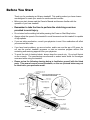
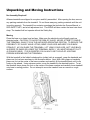
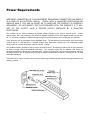
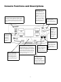
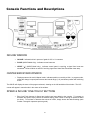
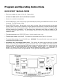
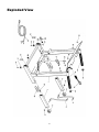
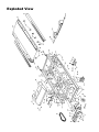
Alliance 815/835HR TREADMILL OWNER’S MANUAL Alliance Fitness Treadmills Manufactured in the USA by: KEYS Fitness Products, LP P.O. Box 551239 Dallas, Texas 75239 www.keysfitness.com TABLE OF CONTENTS PAGE Table of Contents 2 Important Safety Information 3 Before You Start 4 Warm Up Exercises 5 Unpacking and Moving Instructions 6 Power Requirements 7 Console Functions and Descriptions 8, 9, 10 Program and Operating Instructions 11, 12, 13 Program Descriptions and Profiles 14 Belt Adjustments and Tension 15 Maintenance Instructions 16 Troubleshooting Guide 17 Parts and Diagrams 18,19,20 Warranty Registration (Mail In Form) 2 21 Important Safety Information NING! 1) WARNING: Before using this treadmill or starting any exercise program, consult your physician. This is especially important for persons over the age of 35 and/or persons with pre-existing health problems. The manufacturer or distributor assumes no responsibility for personal injury or property damage sustained by or through the use of this product. 2) WARNING: To reduce the risk of electrical shock, burns, fire, or other possible injuries to the user, it is important to review this manual and the following precautions before operation. SAFETY PRECAUTIONS AND TIPS It is the owner’s responsibility to ensure that all users of this treadmill have read the Owner’s Manual and are familiar with warnings and safety precautions. This treadmill has a user maximum capacity of 275 pounds. The treadmill should only be used on a level surface and is intended for indoor use only. The treadmill should not be placed in a garage, patio, or near water and should never be used while you are wet. We recommends a treadmill mat be placed under the treadmill to protect floor or carpet and for easier cleaning. Follow safety information in regards to plugging in your treadmill. Keep the power cord away from the incline wheels and do not run the power cord underneath your treadmill. Do not operate the treadmill with a damaged or frayed power cord. Wear comfortable, good-quality walking or running shoes and appropriate clothing. Do not use the treadmill with bare feet, sandals, socks or stockings. Always straddle the belt and allow it to start moving before stepping onto the belt. Hold on to handrails when adjusting speed, incline, or other controls. Always examine your treadmill before using to ensure all parts are in working order. Allow the belt to fully stop before dismounting. Pets should be never be allowed near or on the treadmill. Do not leave children unsupervised near or on the treadmill. Never operate the treadmill where oxygen is being administered, or where aerosol products are being used. Never insert any object or body parts into any opening. For safety and to prevent damage to your treadmill, no more than one person should use the treadmill at a time. Always unplug the treadmill before cleaning and/or servicing. Service to your treadmill should only be performed by an authorized service representative, unless authorized and/or instructed by the manufacturer. Failure to follow these instructions will void the treadmill warranty. Never leave the treadmill unattended while it is running. 3 Before You Start Thank you for purchasing an Alliance treadmill! This quality product you have chosen was designed to meets your needs for cardiovascular exercise. • Before you start, please read the Owner’s Manual and become familiar with the operation of your new treadmill. • Remember to take the time to perform the stretching exercises provided to avoid injury. • Do not stand on the walking belt while pressing the Power or Start/Stop button. • Always adjust the speed of the treadmill in small increments as this treadmill is capable of high speeds. • If you are taking medication, consult your physician to see if the medication will affect your exercise heart rate. • If you have heart problems, you are not active, and/or are over the age of 50 years, do not use the pre-set treadmill programs or start an exercise program without first contacting and receiving approval from your physician. • To avoid the risk of electrical shock, always keep the console dry. Do not spill liquids on the console. The manufacturer recommends a sealed water bottle for beverages consumed while using the treadmill. • Please review the following drawing below to familiarize yourself with the listed parts. This manual covers several treadmills, so the one pictured below may not be identical to your particular model. 4 Warm Up Exercises NING! WARM UP FIRST ! Warming up prepares the body for exercise by increasing circulation, supplying more oxygen to the muscles and raising body temperature. Begin each workout with 5 to 10 minutes of stretching and light exercise to warm up. The drawings on this page show several forms of basic stretching you may perform before your workouts. Again, consult a physician before starting this or any other exercise program. 15 Seconds for each 25 Seconds 30 Seconds 20 Seconds 25 Seconds each leg 20 Seconds 20 Seconds 25 Seconds each leg 5 Seconds X 3 times 5 Times 5 20 Seconds 20 Seconds 30 Seconds 20 Seconds 15 Seconds Unpacking and Moving Instructions No Assembly Required! Alliance treadmills are shipped in one piece and fully assembled. After opening the box, remove any packing materials from the treadmill. Do not throw away any packing materials until the unit is working properly. The treadmill box contains a package that includes the Owners Manual, a RED SAFETY KEY, and a belt adjustment tool. The 835HR will also contain the heart rate chest strap. The treadmill will not operate without the Safety Key. Moving Place the base on a clean, level surface. Make sure the electrical cord will easily reach an electrical outlet. CAUTION ! TO AVOID THE RISK OF INJURY, NEVER ATTEMPT TO MOVE THE TREADMILL WHILE IT IS IN THE UNFOLDED OPERATING POSITON. TO REDUCE THE POSSIBILITY OF INJURY WHILE LIFTING, BEND YOUR LEGS AND KEEP YOUR BACK STRAIGHT. AS YOU RAISE THE TREADMILL, LIFT USING YOUR LEGS, NOT YOUR BACK. IN ORDER TO RAISE OR LOWER THE TREADMILL SAFELY, YOU MUST BE ABLE TO LIFT 45 POUNDS (20KG). IT IS SUGGESTED YOU ALWAYS USE THE AID OF A SECOND PERSON WHEN MOVING THE TREADMILL. With the treadmill in the folded locked position (safety latch is engaged), grasp the handrails and place one foot on base as shown in the illustration below. Next, with a firm grasp on handrails, place one foot on the center of the base crossbar and carefully tilt the treadmill back until it rolls freely on the wheels. Using extreme caution, move the treadmill to the desired location. To set the treadmill down, place one foot on the center of the base crossbar and carefully lower treadmill onto base in resting position. Do not attempt to move the treadmill over an uneven or rough surface. 6 Power Requirements WARNING! IMPROPER CONNECTION OF THE EQUIPMENT GROUNDING CONNECTOR CAN RESULT IN A RISK OF AN ELECTRIC SHOCK. CHECK WITH A QUALIFIED ELECTRICIAN OR SERVICE MAN IF YOU ARE IN DOUBT AS TO WHETHER THE PRODUCT IS PROPERLY GROUNDED. DO NOT MODIFY THE PLUG PROVIDED WITH THE PRODUCT, IF IT WILL NOT FIT THE OUTLET, HAVE A PROPER OUTLET INSTALLED BY A QUALIFIED ELECTRICIAN. This treadmill can be seriously damaged by sudden voltage changes in your home’s electrical power. Voltage spikes, surges, and noise interference can result from weather conditions or from other appliances being turned on or off. To reduce the possibility of treadmill damage, always use a surge protector (not included) with your treadmill. Surge protectors can be purchased at most hardware stores. The manufacturer recommends a single outlet surge protector with a UL 1449 rating as a Transient Voltage Surge Suppressor (TVSS) with a UL suppressed voltage rating of 400V or less and an electrical rating of 120VAC, 15 amps. This treadmill must be grounded to reduce the risk of electrical shock. Grounding provides a path of least resistance for electric current, should the treadmill malfunction. This treadmill comes with an electrical cord having an equipment-grounding conductor and a grounding plug. Always plug the power cord into a surge protector, and plug the surge protector into an appropriate outlet that is properly installed and grounded in accordance with all local codes and ordinances. This product is for use on a nominal 120-volt circuit, and has a grounding plug that looks like the plug illustrated in the drawing (1) below. 7 Console Functions and Descriptions START/STOP - This button starts the treadmill belt moving. There is a 4 second countdown built in as a safety feature to let you know the treadmill belt is about to start moving. Use the START/STOP button also to stop your treadmill after your workout. The belt will gradually come to a stop after pressing the button. PROGRAM BUTTONS - These buttons are used to access each of the three programs: Fat Burn, Cardio, and Warm Up. Each program has one preset program, and two additional custom programs in the P1 and P2 mode. See the “Program and Operating Instructions” on page 12. PAUSE - Press to temporarily pause your workout while in use. The treadmill is designed with an automatic power off feature after 5 minutes in the pause mode. ENTER - Use the Enter button while setting program time, speed, and incline options. See page 12 for complete ONE TOUCH INCLINE BAR - Use to either increase or decrease the incline. Each number indicates percent of grade. Pressing one of the buttons will gradually increase or decrease the incline to the POWER - Press to on. Allow 6-8 seconds while the electronics perform a self check prior to pressing other CONSOLE SAFETY KEY - Place the RED Safety Key here prior to turning power on. THE TREADMILL WILL NOT OPERATE WITHOUT THE SAFETY KEY ATTACHED. The safety key is equipped with a string and clip that will clip to your clothing. This is an important safety feature that will automatically turn the power off if you should trip or fall while using the treadmill. INCLINE - Use to either increase (UP arrow) or decrease (DOWN arrow) the incline. These buttons are also used while programming INCLINE. ONE TOUCH SPEED BAR Use to either increase or decrease the speed. Each number indicates MPH. Pressing one of the buttons will gradually increase or decrease the speed to the new setting. 8 SPEED - Use to either increase (UP arrow) or decrease (DOWN arrow) the speed. These buttons are also used while programming SPEED and TIME. Console Functions and Descriptions There are five display windows on the control panel to provide feedback information. TIME WINDOW • TIME: Indicates elapsed time after pressing start in minutes and seconds (0-99 minutes, 0-59 seconds) • INTERVAL TIME: Indicates countdown in seconds to the next interval starting at 5 seconds and counting to 0 seconds SPEED WINDOW • SPEED: Indicates MPH (miles per hour) or KMH (kilometer per hour) in .1 increments DISTANCE / CALORIES WINDOW • DISTANCE: Indicates Miles or Kilometers traveled in .01 increments up to 9.99 and .1 increments starting at 10.0 • CALORIES: Indicates estimated calories used based on 150 lb. person at the indicated speed, incline, and time 9 Console Functions and Descriptions INCLINE WINDOW • INCLINE: Indicates incline in percent of grade 0-12% in 1 increments • PULSE (835HR Model Only): Indicates current heart rate • HEART “♥” (835HR Model only): Indicates control panel is receiving a signal from heart rate transmitter. Heart will blink on and off if receiving signal from Heart Rate Transmitter chest strap. CENTER BRICKYARD WINDOW • Displays quarter mile track in Manual mode. Indicates position on track by a blink. In program mode, shows the change in speed profile across the interval range (1-10) and shows position with a blinking action. The 835HR will display the name of the program selected, showing on the left hand side of the window. The LAP counter will appear in manual mode in the center of the window. SPEED & INCLINE “ONE-TOUCH” BUTTONS • Easy One-Touch buttons for Speed and Incline have been added to the console. To increase or decrease the speed, simply choose the desired setting (each number 2 through 8 represents Miles per Hour). To increase or decrease the amount of incline, simply choose the desired setting (each number 2 through 8 represents percent grade). 10 Program and Operating Instructions QUICK START / MANUAL MODE • Plug into a standard wall outlet (110-Volt AC, 15-amp circuit). • ATTACH THE RED SAFETY KEY TO CENTER OF CONSOLE. • Stand on the treadmill and straddle belt. • Press POWER button. There will be an eight (8) second delay after pressing the POWER button before data can be entered. The TIME window will flash. • Press START/STOP button. Belt will begin to move after 4 seconds. Step on belt slowly after the belt starts moving. Speed or incline may be adjusted by using the appropriate UP (increase) or DOWN (decrease) buttons. Speed and Incline can also be adjusted using the “One Touch” buttons labeled 2 through 8, or by using the toggle switches located on the handlebars. For speed and incline adjustments while using the treadmill, try the convenient handlebar toggles switches. The left handlebar switch is for incline, while the right handlebar switch adjusts the speed. • To end your workout, press START/STOP button. Belt will gradually slow to zero. • To pause your workout, press PAUSE. The treadmill will automatically shut off after five (5) minutes. • To re-start after pausing: Press the PAUSE button. WARNING: The treadmill belt will resume at the speed the treadmill was moving before pausing. • Countdown Time, Preset Speed and/or Incline: Time, Speed, and Incline may be preset prior to getting started. After pressing the POWER button, the time window will blink. Use the SPEED UP or DOWN arrows to select your workout time, then press the ENTER button located on the left hand side of the console below the program buttons. The SPEED/TIME window will now be flashing. Using the same + or – arrows, select the speed for your workout, then press ENTER. Now the INCLINE window will be flashing. Use the INCLINE + or – arrows to set your workout incline, then press ENTER. To start, press the START/STOP button. 11 Program and Operating Instructions PROGRAM MODE • Plug into a standard wall outlet (110-Volt AC, 15-amp circuit). • ATTACH THE RED SAFETY KEY TO THE CENTER OF THE CONSOLE. • Stand on the treadmill and straddle belt. • Press POWER button. There will be an eight (8) second delay after pressing the POWER button before data can be entered. The TIME window will flash. • There are three (3) pre-set programs on the 815 and 835HR. Both include Fat Burn, Cardio, and Warm Up programs. The 835HR also includes a Heart Rate Control program (see the program profiles later in this manual). Select the program by pressing the appropriate button. • Press START/STOP button. Belt will begin to move after 4 seconds. Step on belt slowly after the belt starts moving. • Each of the pre-set programs (6) can also be customized. particular model. • Customizing programs in P1 and P2 Mode: Each pre-set program can be customized in the P1 or P2 mode. After making the program selection, the center window will read “OP.” ”OP” refers to “original program” and is preset. Press the same program button once more, and the center window will read P1. The “P1” mode is now accessed. You can now program the Time, Speed, and Incline in P1 mode, which will save your entered information for future use. The time window will blink. Use the SPEED UP or DOWN arrows to select your workout time, then press the ENTER button located on the left hand side of the console below the program buttons. The SPEED window will now be flashing. Using the SPEED UP or DOWN arrows, select the speed for your workout, then press the ENTER button. Now the INCLINE window will be flashing. Use the INCLINE UP or DOWN arrows to set your workout incline, then press the ENTER button. To start, press the START/STOP button. To access P2 mode, press the selected program button three times (once for OP, twice for P1, three times for P2). Follow the above procedure to customize. • TO CHANGE A PREVIOUSLY PROGRAMMED P1, P2, or user program: Once you have programmed the P1 or P2 modes, you will need to use the PAUSE button to change the program you previously entered. For instance, if P1 in Fat Burn has been programmed, to change to a new setting, press the Fat Burn button twice to access P1. Then press the PAUSE button to get the TIME window to flash. Follow the directions above to continue to change the program. 12 Follow the instructions below for your Program and Operating Instructions Heart Rate Control Instructions (835HR only) HEART RATE PROGRAM MODE The Heart Rate program is designed to keep your heart rate a desired level of “beats per minute” by automatically adjusting the incline. For example, if you have programmed in a desired heart rate of 105 beats per minute and your heart rate is only 95 beats per minute (you must be wearing Heart Rate Transmitter), the incline will automatically increase to intensify the work load, and increase you heart rate to the 105 beats per minute you programmed. If your heart rate is above your programmed amount of beats per minute the incline will automatically decrease to lower your heart rate. You may at any time during the Heart Rate Program adjust/override the speed and or incline by simply pressing the correct corresponding buttons. You may change your “Target Heart Rate” at ant time during the program by pressing the TARGET + or TARGET – buttons. • Plug into a standard wall outlet (110-Volt AC, 15-amp circuit). Attach Safety Key to console • Place the Heart Rate transmitter strap across chest against the skin. Stand on the treadmill and straddle belt. • Press POWER button. There will be an eight (8) second delay after pressing the POWER button before data can be entered. The TIME window will flash. The “Heart” shape on the treadmill will be flashing if the Heart Rate Transmitter is transmitting. Adjust the strap on the chest until the console is picking up a signal. • For Quick Start, press START/STOP button. Belt will begin to move after 4 seconds. Step on belt slowly after the belt starts moving. Speed or incline may be adjusted by using the appropriate + (increase) or – (decrease) buttons. Heart rate will read out in the Incline window. • To select the Heart Rate Control program, press the “Heart Rate Control” button. • The incline window will flash “125”, which is the default program target heart rate. • Adjust Target Heart Rate to desired level with the TARGET + or – buttons. • Press START/STOP button, or continue instructions below to program Time, Speed and Incline. • You can now program the Time, Speed, and Incline. The time window will blink. Use the SPEED/TIME + or – arrows to select your workout time, then press the ENTER PROGRAM button. The SPEED/TIME window will now be flashing. Using the same + or – arrows, select the maximum speed for your workout, then press ENTER PROGRAM. Now the INCLINE window will be flashing. Use the INCLINE + or – arrows to set your maximum workout incline, then press ENTER PROGRAM. To start, press the START/STOP button. 13 Program Profiles The FAT BURN program is designed to vary treadmill elevation while maintaining a constant walking speed. Set the desired maximum speed and incline, and the treadmill will automatically change the incline to the set amount, alternating in segments 2-3, 5-6, and 8-9. The CARDIO program is designed to vary treadmill speed while maintaining a constant incline. Set the desired maximum speed and incline, and the treadmill will automatically change the speed to the set amount, alternating in each segment. EACH PROGRAM HAS 10 SEGMENTS. THE LENGTH OF TIME FOR EACH SEGMENT IS BASED ON THE TIME LENGTH OF THE PROGRAM. IF YOU SET THE PROGRAM TO 30 MINUTES, EACH SEGMENT IS 3 MINUTES LONG (TIME divided by 10 segments). YOU CAN ALSO CUSTOMIZE THE TIME, SPEED, AND INCLINE FOR EACH OF THESE PROGRAMS. SEE PAGE 12 FOR PROGRAMMING THE P1 AND P2 MODES. The WARM UP program is designed to gradually increase treadmill speed and incline (warm up) in the first segment to the set maximum speed and incline. At the end of the program, the treadmill will gradually decrease speed and incline to half of the maximum set (cool down) in segments 9-10. 14 Belt Adjustment and Tension WARNING! Do not overtighten rollers! This will cause premature roller bearing failure! Belt adjustment and tension performs two functions: adjustment for tension and centering. Your new treadmill comes pre-adjusted from the factory for tension and centering. Please follow the procedures below if the belt shifts left or right or if the belt slips while walking: WALKING BELT HAS SHIFTING TO THE LEFT (Diagram 1) First, unplug the power cord from the surge protector. Using the hex key provided, turn the left rear roller adjustment bolt ¼ turn in the clockwise direction. Plug the power cord back into the surge protector and run the treadmill at 2.5 mph. You should see the belt start to correct itself, moving back towards the center. Repeat the above procedure until the walking belt is centered. It may be necessary to set walking belt tension once you have completed this procedure if the belt feels like it is slipping while walking. Refer to below to the “Walking Belt Slipping” instructions. WALKING BELT HAS SHIFTING TO THE RIGHT (Diagram 2) First, unplug the power cord from the surge protector. Using the hex key provided, turn the right rear roller adjustment bolt ¼ turn in the clockwise direction. Plug the power cord back into the surge protector and run the treadmill at 2.5 mph. You should see the belt start to correct itself, moving back towards the center. Repeat the above procedure until the walking belt is centered. It may be necessary to set walking belt tension once you have completed this procedure if the belt feels like it is slipping while walking. Refer to below to the “Walking Belt Slipping” instructions. WALKING BELT IS SLIPPING DURING USE (Diagram 3) First, unplug the power cord from the surge protector. Using the hex key provided, turn both left and right rear roller adjustment bolts the same distance, usually a ¼ turn in the clockwise direction. Plug the power cord back into the surge protector and run the treadmill at 2.5 mph. You should now walk on the belt to determine if the belt is still slipping. Repeat the above procedure until the walking belt is not slipping. The tension should be just tight enough not to slip. 15 Maintenance Instructions WARNING! Before performing any maintenance to your treadmill, always unplug the power cord from the surge protector. CLEANING Routine cleaning of your Alliance Fitness treadmill will extend the life of your treadmill. WARNING! To prevent electrical shock, be sure the power to the treadmill is OFF and the unit unplugged from the wall electrical outlet before attempting any cleaning or maintenance. AFTER EACH WORKOUT: Wipe off the console and other treadmill surfaces with a clean, water dampened soft cloth to remove excess perspiration. USE NO CHEMICALS. WEEKLY: Use of a treadmill mat is recommended for ease of cleaning. Dirt from your shoes contacts the belt and eventually makes it to underneath the treadmill. Vacuum underneath treadmill once a week. DECK LUBRICATION The walking belt has been pre-lubricated at the factory. However, it is recommended that the walking board be checked periodically for lubrication to ensure optimal treadmill performance. Your treadmill should not have to be lubricated usually within the first year or 500 hours of use. If you have questions, call us at (888) 340-0482. Every 30 days or 30 hours of operation, lift the sides of the walking belt and feel the top surface of the walking board as far under as you can reach. If you feel signs of silicone, no further lubrication is required. If it feels dry to the touch, follow the instructions below. Please use Lube ‘N Walk (can be purchased from your dealer or call the number on the front of the manual), or a non-petroleum based silicone such as “Napa 8300” (available at most stores). TO APPLY LUBRICANT TO THE WALKING BOARD 1) Position the walking belt so that the seam is located on top and in the center of the center of the walking board. 2) Insert the spray nozzle into the spray head of the lubricant can. 3) While lifting the side of the walking belt, position the spray nozzle between the walking belt and the board approximately 6” from the front of the treadmill. Apply the silicone spray to the walking board, moving from the front of the treadmill to the rear. Repeat this on the other side of the belt. Spray approximately 4 seconds on each side. 4) Allow the silicone to ‘set’ for one minute before using the treadmill. 16 Troubleshooting Guide Treadmill will not start. 1) Is the RED Safety Key Attached to the Console? 2) Make sure the power cord is plugged into a surge protector, the surge protector is plugged into a properly grounded outlet, and the surge protector is turned on. (Refer to “Power Requirements”) 3) Check the circuit breaker located on the front of the treadmill. If the switch protrudes, it has tripped. Wait five minutes and then press the switch back in. 4) Check the house electrical breaker box and the circuit breaker for the room the treadmill is located in. If it has tripped, reset or have an electrician replace the breaker in home. 5) Have an electrician check for inadequate voltage at the outlet. Treadmill looses power during use. 1) Check the circuit breaker located on the front of the treadmill. If the switch protrudes, it has tripped. Wait five minutes and then press the switch back in. 2) Check the house electrical breaker box and the circuit breaker for the room the treadmill is located in. If it has tripped, reset or have an electrician replace the breaker in home. 3) If treadmill still will not operate, please call Keys Technical Service at (888) 340-0482. Treadmill walking belt slows during use. 1) Check to make sure the treadmill is securely plugged into an UL-listed surge protector, rated at 15 amps, with a 14-guage cord of five feet or less and the surge protector is securely plugged into the outlet. 2) If treadmill still will not operate, please call Keys Technical Service at (888) 340-0482. Treadmill walking belt slips or is not centered on rear roller. 1) Refer to “Belt Adjustment and Tension” section. 2) Need help? Call Keys Technical Service at (888) 340-0482. Treadmill Error Messages. 2)Your treadmill is equipped with a software package that enables error messages to be displayed when there is a problem. To avoid possible damage to the treadmill and the possibility of injury, do not operate the treadmill until the problem is corrected. Call Keys Technical Service at (888) 3400482. 17 Parts List - Alliance 815 and 835HR KEY # QTY KEY # PART # 1 UP 3K ASSB PART # UPRIGHT ASSEMBLY DESCRIPTION 1 53 08-0004 CIRCUIT BREAKER 15 AMP 1 2 20-0001 DECK ASSEMBLY 1 54 13-0017 TELCO HARNESS FOR HEART RATE 1 3 20-0003 ELEVATION ASSEMBLY 1 55 11-0002 REAR ELEVATION BUSHING 2 4 SES EXT S.E.S. EXTENSION TUBE 2 56 11-0003 UPRIGHT PIVOT BUSHING 2 5 19-0010 UPRIGHT PIVOT BRACKET 2 6 19-0013 SAFETY LATCH 1 58 14-0162 SIDE FRAME DECAL ALLIANCE 2 7 19-0014 MOTOR MOUNTING BRACKET 1 59 CONSOLE DECAL 1 8 19-0015 MOTOR COVER BRACKET 6 60 14-0053 AND 140054 14-0190 MOTOR COVER DECAL ALLIANCE 1 9 19-0029 OPTICAL WHEEL BRACKET 1 62 14-0024 SAFETY LATCH DECAL N/S 1 10 19-0019 BELT GUIDE 2 63 14-0025 WARNING FOLDING DECAL N/S 1 64 14-0026 WARNING CONSOLE DECAL N/S 1 MOTOR TENSION SPRING 1 12 19-0032 SPRING ANCHOR BRACKET 2 65 02-0078 13 06-0018 BASE PAN MOTOR 1 66 02-0002A 24-0091 CONSOLE ASSEMBLY 815 1 67 16 05-0001 SIDE BOARD EXTRUSION 2 17 06-0027 PIVOT SUPPORT COVER 19 07-0041 21 22 DESCRIPTION QTY DECK LIFT SPRING 4 02-0004 SCREW, 8X 5/8 PHIL PH 40 68 02-0005 SCREW, 8X 5/8 PHIL PH HILO 8 69 02-0006 BOLT, 5/16 X 5 - 1/2 SHOULDER BOLT 1 2 70 02-0007 5/16-18 NYLOCK NUT 3 HEART RATE CHEST STRAP no t shown 1 71 02-0008 BOLT, 5/16-18 X 3/4 GRADE 2 ZP 3 06-0053 3-PC LCD CENTER PLASTIC CONSOLE 1 72 02-0009 NUT, 5/16-18 WHIZLOC 3 06-0071 FAN 5" 5/8” ID 1 76 02-0013 LOCK WASHER, 1/4 8 23 06-0020 BASE PAN END 1 77 02-0014 BOLT, 1/4-20 X 2 - 1/2 HEX 10 24 06-0004 BASE PLUG 2 78 02-0015 SPRING WASHER 4 25 06-0005 DOME PLUG 4 79 02-0016 BOLT, 3/8-16 X 2 - 1/2 HEX 1 26 06-0007 MOTOR COVER 1 80 02-0017 NUT, 3/8-16 NYLOCK 2 27 06-0008 END CAP 1 81 02-0018 PUSH NUT, 3/8 HAT 4 28 06-0009 S.E.S. EXTENSION GLIDE 4 82 02-0019 CARRIAGE BOLT 10-24 X 1-1/2 4 29 06-0019 BASE PAN CENTER 1 83 02-0020 SCREW, 1/4-20 X 2-1/2 SOCKET HEAD 2 30 06-0011 2" ROLLER WHEEL 2 84 02-0021 WASHER, 9/32 X 5/8 X 1/8 3 31 06-0012 3” ROLLER WHEEL 2 85 02-0022 NUT, 10-24 NYLOCK 4 32 06-0013 UPRIGHT SPACE 2 87 02-0024 CARRIAGE BOLT 5/16 X 1 2 33 10-0004 RUBBER FOOT 3 88 02-0025 WHEEL AXLE 2 34 10-0002 BOARD ISOLATOR 8 89 02-0026 PUSH NUT 10 35 10-0013 GRIP MOLDED WITH REMOTE 2 91 02-0028 SAFETY KEY 1 36 07-0020 HEART RATE RECEIVER NOT SHOWN 1 93 02-0030 SCREW, 8-32 X 5/8 HEX TRILOBE 1 37 12-0022 ACTUATOR (ELEVATION MOTOR) 1 94 02-0031 SCREW, 3/8-16 X 1 3/4 HEX 1 38 12-0021 DRIVE MOTOR 1 39 03-0004 WALKING BOARD 1 08-0090 MEM, LCD PROG HR 815HR 40 04-0008 WALKING BELT 18" X 105" 1 97 02-0034 SCREW, 8-32 X 5/8 PPH N/SHOWN 1 41 04-0004 POLY V BELT 1 98 02-0035 NUT, 8-32 NYLOCK NOT SHOWN 4 42 09-0012 FRONT ROLLER ASSEMBLY 1 99 02-0036 SCREW, GREEN HEAD 8 X 5/8 PPH 2 43 09-0013 REAR ROLLER 1 08-0094 MEM, LCD PROGRAM WITH INCLINE 815 1 44 13-0011 POWER CORD 1 08-0089 MEM, LCD POWER 815 AND 835HR 1 45 13-0003 ENCODER HARNESS 1 103 02-0040 GUIDE TUBE RETAINER NOT SHOWN 1 14-0168 OVERLAY 815 W/ SPEED BAR 1 104 14-0027 EMERGENCY STOP DECAL 1 14-0152 OVERLAY PROGRAM 835HR 1 105 06-0014 BUSHING, STRAIN RELIEF 1 48 13-0016 CONTROL PANEL HARNESS 1 107 06-0016 WIRE TIES NOT SHOWN 10 49 13-0007 JUMPER WIRE 6" NOT SHOWN 1 108 06-0021 WIRE CLAMP NOT SHOWN 5 07-0028 UPPER LCD ELECTRONICS 1 109 06-0022 RESET GUIDE TUBE NOT SHOWN 1 51 08-0014 MOTOR CONTROLLER 1 110 06-0024 HEX WRENCH CLIP NOT SHOWN 1 52 08-0047 OPTICAL ENCODER 1 111 10-0007 6" CROSS HANDLEBAR FOAM GRIP 18 2 Exploded View 19 Exploded View 20 Alliance 815 and 835HR Treadmills manfactured by KEYS FITNESS PRODUCTS, LP – LIMITED WARRANTY PLEASE CONSULT YOUR PHYSICIAN BEFORE USING THIS PRODUCT. This Limited Warranty applies in the United States, Canada, and Mexico to products manufactured or distributed by Keys Fitness Products, LP (“Keys”) under the ALLIANCE brand name. The warranty period to the original purchaser is (lifetime) on the frame, (10) years on the motor, (5) years on the walking belt and deck, (2) years on parts, and (1) year labor. This warranty does not cover wear and tear, only manufacturer defects for the periods specified. Keys warrants that the Product you have purchased for non-commercial, personal, family, or household use from Keys or from an authorized Keys reseller is free from defects in materials or workmanship under normal use during the warranty period. Your sales receipt, showing the date of purchase of the Product, is your proof of the date of purchase. This warranty only extends to you, the original purchaser. It is not transferable to anyone who subsequently purchases the Product from you. It excludes expendable parts. This Limited Warranty becomes VALID ONLY if the treadmill is assembled/installed by a Keys Fitness authorized dealer/technician unless otherwise authorized by Keys Fitness in writing (if anyone other than a Keys Fitness authorized dealer/technician assembles a Keys Fitness treadmill the warranty will be void unless accompanied by written authorization by Keys Fitness). Select models do not require assembly, and the original purchaser During the warranty period Keys will at no additional charge, repair or replace (at Keys’ option) the part or product if it becomes defective, malfunctions, or otherwise fails to conform with this Limited Warranty under normal non-commercial, personal, family or household use. In repairing the Product, Keys may replace defective parts, or at the option of Keys, serviceable used parts that are equivalent to new parts in performance. All exchanged parts and Products replaced under this warranty will become the property of Keys. Keys reserves the right to change manufacturers of any part to cover any existing warranty. To obtain warranty service, you must contact a Keys authorized service technician or Keys Fitness at our phone numbers located in this manual. Any parts determined to be defective must be returned to Keys to obtain warranty service. You must prepay any shipping charges, export taxes, custom duties and taxes, or any other charges associated with transportation of the parts or Product. In addition, you are responsible for insuring any parts or Product shipped or returned. You assume the risk of loss during shipment. You must present Keys with proof-of-purchase documents (including the date of purchase). Any evidence of alteration, erasing or forgery of proof-of-purchase documents will be cause to void this Limited Warranty. This warranty does not extend to any product not purchased from Keys or from an authorized Keys reseller. This Limited Warranty does not extend to any Product that has been damaged or rendered defective; (a) as a result of accident, misuse, or abuse; (b) by the use of parts not manufactured or sold by Keys; (c) by modification of the Product or normal wear and tear; (d) operation on incorrect power supplies; or (e) as a result of service by anyone other than Keys, or an authorized Keys warranty service provider. Product on which the serial number has been defaced or removed is not eligible for warranty service. Should any Product be submitted for warranty service be found ineligible therefore, an estimate of repair cost will furnished and the repair will be made if requested by you upon Keys’ receipt of payment or acceptable arrangements for payment. EXCEPT AS EXPRESSLY SET FORTH IN THIS WARRANTY, KEYS MAKES NO OTHER WARRANTIES, EXPRESSED OR IMPLIED, INCLUDING ANY IMPLIED WARRANTIES OF MERCHANTABILITY AND FITNESS FOR A PARTICULAR PURPOSE. KEYS EXPRESSLY DISCLAIMS ALL WARRANTIES NOT STATED IN THIS LIMITED WARRANTY. ANY IMPLIED WARRANTIES THAT MAY BE IMPOSED BY LAW ARE LIMITED TO THE TERMS OF THIS LIMITED WARRANTY. NEITHER KEYS NOR ANY OF ITS AFFILIATES SHALL BE RESPONSIBLE FOR INCIDENTAL OR CONSEQUENTIAL DAMAGES. SOME STATES DO NOT ALLOW LIMITATIONS ON HOW LONG AN IMPLIED WARRANTY LASTS OR THE EXCLUSION OR LIMITATION OF INCIDENTAL OR CONSEQUENTIAL DAMAGES, SO THE ABOVE LIMITATIONS OR EXCLUSION MAY NOT APPLY TO YOU. This Limited Warranty gives you specific legal rights and you may also have other rights that may vary from state to state. This is the only express warranty applicable to Keys-branded products. Keys neither assumes nor authorizes anyone to assume for it any other express warranty. PLEASE SEND IN THE ATTACHED WARRANTY CARD WITHIN TEN (10) DAYS OF PURCHASE TO REGISTER YOUR TREADMILL WITH KEYS FITNESS PRODUCTS, LP. MADE IN THE USA. Thank you for your business! PLEASE MAIL WARRANTY CARD TO: KEYS FITNESS PRODUCTS, PO BOX 551239, DALLAS, TX 75355. 21