1
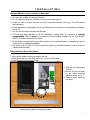
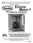
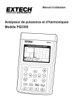
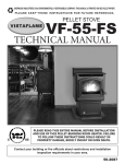
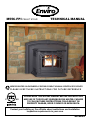
M55C-FPI PELLET STOVE TECHNICAL MANUAL SHERWOOD INDUSTRIES IS AN ENVIRONMENTALLY RESPONSIBLE COMPANY. THIS MANUAL IS PRINTED ON RECYCLED PAPER. PLEASE KEEP THESE INSTRUCTIONS FOR FUTURE REFERENCE PLEASE READ THIS ENTIRE MANUAL BEFORE INSTALLATION AND USE OF THIS PELLET-BURNING ROOM HEATER. FAILURE TO FOLLOW THESE INSTRUCTIONS COULD RESULT IN PROPERTY DAMAGE, BODILY INJURY OR EVEN DEATH. Contact your building or fire officials about restrictions and installation inspection requirements in your area. 50-2259 Table of Contents Safety Warnings & Recommendations...............................................................................................3 Specifications.................................................................................................................................5 Rating Label & Location............................................................................................................5 Dimensions..............................................................................................................................6 Specifications...........................................................................................................................6 Installation.....................................................................................................................................7 Deciding Where to Locate your Pellet Appliance..........................................................................7 Removing Pellet Stove From Pallet.............................................................................................7 Installing the Insert Frame & Levelling...........................................................................................8 Clearances to Combustibles.......................................................................................................9 Thermostat Installation.............................................................................................................9 Vent Termination Requirements.................................................................................................10 Outside Fresh-Air Connection...................................................................................................11 Exhaust And Fresh Air Intake Locations....................................................................................11 Masonry Fireplace Installation...................................................................................................12 Positive Flue Connection...........................................................................................................13 Built-In Installation..................................................................................................................14 Horizontal Exhaust Through Wall Installation...............................................................................15 Through Wall With Vertical Rise and Horizontal Termination Installation..........................................16 Outside Vertical Installation.......................................................................................................17 Inside Vertical Installation........................................................................................................18 Slider/Damper Set-Up..............................................................................................................19 Troubleshooting.........................................................................................................................20 Wiring Diagram.............................................................................................................................23 Parts List......................................................................................................................................24 Parts Diagram - Components..........................................................................................................27 Parts Diagram - Steel....................................................................................................................28 Warranty......................................................................................................................................29 Installation Data Sheet..................................................................................................................32 2 Safety Warnings & Recommendations * This manual is designed for the technician in conjunction with the owner’s manual. * Please read this entire Technical Manual before installing or operating your Enviro Pellet Stove. Failure to follow these instructions may result in property damage, bodily injury or even death. Any unauthorized modification of the appliance or use of replacement parts not recommended by the manufacturer is prohibited. All national and local regulations shall be complied with when operating this appliance. Caution: Do not connect to any air distribution duct or system. Warning: Never place wood, paper, furniture, drapes or other combustible materials within 48” (122cm) of the front of the unit, 12” (30.5cm) from each side, and 3” (7.6cm) from the back of the unit. Do not let children or pets touch it when it is hot. To prevent the possibility of a fire, ensure that the appliance is properly installed by adhering to the installation instructions. An Enviro dealer will be happy to assist you in obtaining information with regards to your local building codes and installation restrictions. FIRE EXTINGUISHER AND SMOKE DETECTION: All homes with a pellet burning stove should have at least one fire extinguisher in a central location known to all in the household. Smoke detectors should be installed and maintained in the room containing the stove. If it sounds the alarm, correct the cause but do not deactivate. You may choose to relocate the smoke detection devise within the room; DO NOT REMOVE THE SMOKE DETECTOR FROM THE ROOM. CHIMNEY OR RUN AWAY FIRE: Call local fire department (or dial 911). Close the draft fully. Extinguish the fire in the burn pot liner with a cup of water and close the door. Examine the flue pipes, chimney, attic, and roof of the house, to see if any part has become hot enough to catch fire. If necessary, spray with fire extinguisher or water from the garden hose. IMPORTANT: Do not operate the stove again until you are certain the chimney and its lining have not been damaged. OPERATION: The door and ash drawer must be kept closed when the unit is in operation to prevent fume spillage and for proper and safe operation of the pellet stove. Also ensure all gaskets on the door are checked and replaced when necessary. Unit hot while in operation. Keep children, clothing and furniture away. Contact may cause skin burns. CAUTION: When operating during adverse weather, if the unit exhibits dramatic changes in combustion stop using the unit immediately. FUEL: This stove is designed and approved to only burn wood pellets of any quality, corn, wheat, and barley. Dirty fuel will adversely affect the operation and performance of the unit and may void the warranty. Check with your dealer for fuel recommendations. THE USE OF CORD WOOD IS PROHIBITED BY LAW. Do not burn garbage or flammable fluids such as gasoline, naphtha or engine oil. SOOT: Operation of the stove with insufficient combustion air will result in the formation of soot which will collect on the glass, the heat exchanger, the exhaust vent system, and may stain the outside of the house. Frequently check your stove and adjust the slider/damper as needed to ensure proper combustion. See: “Slider/Damper Setting”. CLEANING: There will be some build up of fly ash and small amounts of creosote in the exhaust. This will vary due to the ash content of the fuel used and the operation of the stove. It is advisable to inspect and clean the exhaust vent semi-annually or every two tons of pellets. The appliance, flue gas connector and the chimney flue require regular cleaning. Check them for blockage prior to re-lighting after a prolonged shut down period. ASHES: Disposed ashes should be placed in a metal container with a tight fitting lid. The closed container of ashes should be on a non-combustible surface, well away from all combustible materials pending final disposal. If the ashes are disposed of by burial in soil or otherwise locally dispensed, they should be retained in the closed container until all cinders have thoroughly cooled. 3 Safety Warnings & Recommendations ELECTRICAL: The use of a surge protected power bar is recommended. The unit must be grounded. The grounded electrical cord should be connected to a standard 110-120 volts (4.2 Amps), 60 hertz electrical outlet and also must be accessible. If this power cord should become damaged, a replacement power cord must be purchased from the manufacturer or a qualified Enviro dealer. Be careful that the electrical cord is not trapped under the appliance and that it is clear of any hot surfaces or sharp edges. This unit’s maximum power requirement is 504 watts. GLASS: Do not abuse the glass by striking or slamming the door. Do not attempt to operate the stove with broken glass. The stove uses ceramic glass. Replacement glass must be purchased from an Enviro dealer. Do not attempt to open the door and clean the glass while the unit is in operation or if glass is hot. To clean the glass, use a soft cotton cloth and mild window cleaner, gas or wood stove glass cleaner, or take a damp paper towel and dip into the fly ash. This is a very mild abrasive and will not damage the glass. KEEP ASH PAN FREE OF RAW FUEL. DO NOT PLACE UNBURNED OR NEW PELLET FUEL IN ASH PAN. A fire in the ash pan may occur. INSTALLATION: Contact your local building or fire official to obtain a permit and any information on installation restrictions and inspection requirements for your area. Be sure to maintain the structural integrity of your home when passing a vent through walls, ceilings, or roofs, and all construction meets local building codes. It is recommended that the unit be secured into its position in order to avoid any displacement. This appliance must be installed on a floor with an adequate load bearing capacity, if existing construction doesn’t meet load capacity, suitable measures (e.g. load distributing plate) must be taken to achieve it. DO NOT INSTALL A FLUE DAMPER IN THE EXHAUST VENTING SYSTEM OF THIS UNIT. DO NOT CONNECT THIS UNIT TO A CHIMNEY FLUE SERVING ANOTHER APPLIANCE. FRESH AIR: This unit uses large quantities of air for combustion; outside Fresh Air connection is strongly recommended. Fresh Air must be connected to all units installed in Mobile and “Air Tight Homes” (R2000) or where required by local codes. Consider all large air moving devices when installing your unit and provide room air accordingly. NOTE: Extractor fans when operating in the same room or space as the appliance may cause problems. Limited air for combustion may result in poor performance, smoking and other side effects of poor combustion. The stove’s exhaust system works with negative combustion chamber pressure and a slightly positive chimney pressure. It is very important to ensure that the exhaust system be sealed and airtight. The ash pan and viewing door must be locked securely for proper and safe operation of the pellet stove. Do not burn with insufficient combustion air. A periodic check is recommended to ensure proper combustion air is admitted to the combustion chamber. Setting the proper combustion air is achieved by adjusting the slider damper located on the left side of the stove. Soot or creosote may accumulate when the stove is operated under incorrect conditions such as an rich burn (black tipped, lazy orange flames). If you have any questions with regards to your stove or the above-mentioned information, please feel free to contact your local dealer for further clarification and comments. Since Sherwood Industries Ltd. has no control over the installation of your stove, SHERWOOD INDUSTRIES LTD. grants no warranty implied or stated for the installation or maintenance of your stove. Therefore, Sherwood Industries Ltd. assumes no responsibility for any consequential damage(s). SAVE THIS INSTRUCTION MANUAL FOR FUTURE REFERENCE. 4 INSTALLED AS A FIREPLACE INSERT STOVE MODEL (FPI) / A INSTALLE COMME UN MODELE SUR PIED DE POELE. DO NOT REMOVE THIS LABEL / NE RETIREZ PAS CETTE ÉTIQUETTE J F M DATE OF MANUFACTURE / DATE DE FABRICATION: A M J J A S O N D 2010 2011 2012 Utilisation avec granules - le bois, le maïs, le blé, & l'orge seulement. Utiliser seulement lorsque les portes avants et la porte du réceptacle de cendre sont fermées. Si une ou des vitres devaient être remplacées, utilisez seulement du verre céramique. Les composantes requises pour l'installation: une rêvetement de cheminée reprisé en acier inoxydable 4”. G F B G A F E C L'APPAREIL EST CHAUD LORSQU'IL FONCTIONNE. NE PAS TOUCHER. GARDER LES ENFANTS, LES VÊTEMENTS ET LES MEUBLES ÉLOIGNÉS DE L'APPAREIL EN MARCHE. UN CONTACT AVEC CELUI-CI MANUFACTURED BY / FABRIQUE PAR: POURRAIT RÉSULTER EN DES BRÛLURES. VEUILLEZ SHERWOOD INDUSTRIES LTD. VOIR LA PLAQUE DU FABRICANT ET LES INSTRUCTIONS. VICTORIA BC CANADA 16622 Certified for use in Canada & USA Certifié pour installation au Canada et aux Etats-Unis. To Start Stove: Select fuel type mode; PREMIUM PELLETS for superior quality pellet fuel, REGULAR PELLETS for all grades of wood pellets & MULTIFUEL for all other fuels. Press the ON / OFF button. For first time use, a small handful of pellets in the burn pot liner will speed up ignition. To Operate Stove: MANUAL MODE: When a fire has been established the stove settings are adjustable. / HIGH/LOW MODE: (Requires a thermostat) When the thermostat calls for heat the stove settings are adjustable. When the thermostat contacts open, the HEAT LEVEL and Fans will drop down to the LOW setting until the thermostat contacts close again. / AUTO/OFF MODE: (Requires a thermostat) When the thermostat contacts close, the unit will light automatically. Once up to temperature the stove settings are adjustable. When the thermostat contacts open, the stove will drop down to the LOW settings for 30 minutes. If within the 30 min the thermostat contacts close, the HEAT LEVEL will return to previous MANUAL setting or if the thermostat contacts remain open the stove begin its shutdown routine and it will restart when the thermostat closes. To Turn Off Stove: MANUAL and HI / LOW mode: Press the ON / OFF button AUTO / OFF mode: Turn the thermostat down or off. Pour démarrer le poêle: Choisir le mode pour le carburant ; PREMIUM PELLETS pour le carburant de boulette de qualité de superior, REGULAR PELLET pour tous degrés de boulettes de bois & MULTIFUEL pour tous autres carburants. Appuyer sur le bouton "ON/OFF". Pour l’usage de première fois, une petite poignée de boulettes dans le pot de brûlure hâtera l'allumage. Pour faire fonctionner le poêle : MODE MANUEL : Lorsque le feu est bien établi, les réglages peuvent être ajustés. / MODE "HIGH/LOW" : (Nécessite un thermostat) Lorsque le thermostat requière de la chaleur, les réglages peuvent être ajustés. Lorsque les contacts du thermostat ouvrent, le réglage du niveau de chaleur et les ventilateurs s'ajusteront au réglage " bas " jusqu'à ce que les contacts du thermostat se referment. / MODE "AUTO/OFF" : (Nécessite un thermostat) Lorsque les contacts du thermostat ferment, le poêle s'allumera automatiquement. Lorsque la température adéquate est atteinte, les réglages peuvent être ajustés. Lorsque les contacts du thermostat ouvrent, le poêle s'ajustera aux réglages "LOW" pendant 30 minutes. Si les contacts du thermostat sont fermés pendant ces 30 minutes, le réglage de niveau de chaleur retournera en réglages "MANUEL" ou si les contacts du thermostat restent ouverts, le poêle entamera le processus d'arrêt et il vouloir redémarrer lorsque les contacts du thermostat refermer. Pour éteindre le poêle : MODE MANUEL ET " HIGH/LOW " : Appuyer sur le bouton "ON/OFF". MODE "AUTO / OFF" : Régler le thermostat à la baisse ou éteignez le. C-12224 ATTENTION: Combustible floors must be protected by a non-combustible material. - See Owners Manual. Le plancher combustible doit être protégé par un matériel incombustible. - Consultez le manual. 6” (152 mm) 6” (152 mm) Figure 1: M55C-FPI Rating Label. HOT WHILE IN OPERATION. DO NOT TOUCH. KEEP CHILDREN, CLOTHING AND FURNITURE AWAY. CONTACT MAY CAUSE BURNS. SEE NAMEPLATE AND INSTRUCTIONS. D From door opening of unit to edge of floor protection (De la porte ouvrant au devant de protection de plancher) From side of unit to edge of floor protection (De l'ouverture de porte pour prendre parti de protection de plancher) Adjacent wall CAUTION: Install and use only in accordance with the manufacturer's installation and operating instructions. Contact local building or fire officials about restrictions and installation inspection in your area. Do not connect this unit to a chimney flue serving another appliance. Inspect and clean exhaust venting system frequently. See local building code and manufacturer's instructions for precautions required for passing a chimney through a combustible wall or ceiling. ELECTRICAL RATING: 120 Volts, 60Hz, 4.2 Amps. Route Cord Away From Heater. For use with pelletized solid fuels - wood, corn, wheat, & barley only. Operate only with viewing door and ash removal door closed. Only replace glass with ceramic glass. Components required for installation: listed 4inch (100 mm) stainless steel chimney liner. Installez et utilisez cet appareil seulement selon les instructions d'installation et d'opération du fabricant. Contactez les autorités locales de votre quartier concernant les restrictions et les inspections d'installation. Inspectez et nettoyez le système d'échappement fréquemment. Consultez les codes de bâtiment locaux et les instructions du fabricant pour les précautions à prendre lorsque une cheminée doit être installée au travers un mur ou un plafond combustible. CLASSEMENT ÉLECTRIQUE : 120 Volts, 60 Hz, 4.2 Amps. Placez le câble électrique loin de la chaleur. Model / Modèle: M55C-FPI Minimum clearances to combustible materials./ Les dégagements minimums aux Listed Room Heater, Pelletized Fuel Type (Appareil de chauffage à granules certifié) matériels combustibles: Input rating when using: Wood Pellets/Corn - 55,000BTU (16.1KW*hr) Wheat/Barley - 53,000BTU (15.5KW*hr) A Sidewall to center of unit (De la paroi au centre de l'unité) 24” (610 mm) B Sidewall to surround panel (De la paroi à l'entoure le panneau) 2” (51 mm) (Le chauffage d'énergie avec: Boulettes de bois/lMaïs - 55,000BTU (16.1KW*hr) Blé/l'Orge - 53,000BTU (15.5KW*hr)) C Bottom of unit to an unshielded 12” (305 mm) mantle Tested to (Testée selon): ASTM 1509-04. US Environmental Protection Agency, certified to comply July 1, 1990, particulate (Le fond de l'unité à un manteau de cheminée non blindé) 33“ (838 mm) emission standards. (États-Unis Environnemental Protection Agence, a certifié pour conformer au Juillet 1, 1990, les normes de D Unit to top facing (protruding ¾” [19 mm]) particules d'émission.) (De l'unité au sommet du parement) 0” (0 mm) Standard for Fireplace Inserts / Norme pour des Insertions de Cheminée: ULC S628 E Unit to side facing (protruding ¾” [19 mm]) (De l'unité au côté du parement) 0” (0 mm) Serial No. / No. De Serié: WH-M55C-FPI Specifications Rating Label & Location: The rating label is located on the top of the hopper. 5 Specifications Dimensions: 16 1/8" 24 3/4" 26 7/8" 12" 32 7/8" 23" 44" Figure 2: Dimensions of M55C-FPI. Specifications: Input rating when using: Wood Pellets/Corn - 55,000BTU (16.1KW•hr) & Wheat/Barley - 53,000BTU (15.5KW•hr). Table 1: M55C-FPI Specifications. Description Residential Pellet Heater Fuel type 6mm (¼”) dia. Pellets - wood, corn, wheat, & barley* Voltage 110 - 120 V Current 4.2 Amps Max Power 504 Watts Frequency 60 Hz Hopper Capacity up to 50 lb (22.7 Kg) Consumption on Low 1.5 lb/hr (0.68 Kg/hr)* Testing Standard ASTM 1509-04 Weight (with full hopper) 370 lb (167.8 Kg) Consumption on High 6.5 lb/hr (2.95 Kg/hr)* *Note: Consumption will vary with the type of fuel used. 6 Installation Deciding Where to Locate your Pellet Appliance: 1. Unit must be installed in a masonry fireplace. 2. Do not install the stove in a bedroom or room where people sleep in. 3. Locate the stove in a large and open room that is centrally located in the house. This will optimize heat circulation. 4. Check clearances to combustibles and for the least amount of interference to house framing, plumbing, wiring, etc. 5. You can vent the stove with approved flex pipe. 6. This unit uses large quantities of air for combustion; outside Fresh Air connection is strongly recommended. Fresh Air must be connected to all units installed in Mobile and “Air Tight Homes” (R2000) or where required by local codes. 7. Do not obtain combustion air from an attic, garage or any unventilated space. Combustion air may be obtained from a ventilated crawlspace. 8. The power cord is 8 feet (2.43 m) long and may require a grounded extension cord to reach the nearest electrical outlet. Removing Pellet Stove From Pallet: 1.Remove the wooden crating surrounding the unit. 2.Remove the cast top, cast sides, cast front, and the cast ash shelf. 3.Unclip the unit from the lower frame. 4.Slide the unit forward and then out. 5.Remove the two top bolts on the pallet mounting plates as shown in Fig. 3. 6. Remove entire frame as one piece. Figure 3: Mounting Plates securing stove to pallet 7 Installation NOTE: Installer must attach the metal “fireplace altered” tag using screws or nails to the fireplace, in a location readily visible should the fireplace insert be removed, if the fireplace has been modified to accomodate the M55C-FPI. Installing the Insert Frame & Levelling: Warning: Careless installation is the major cause of safety hazards. Check all local building and safety codes before installation of unit. 1. Mount Surround Panel to Insert Frame. 2. Place the Insert Frame into the fireplace cavity. 3. Adjust the four levelling bolts until the frame is level. If the fireplace has an un-level surface which exceeds the length of the bolts, masonry bricks may be placed under the frame. 4. Once level, position the Insert Frame in the fireplace cavity so that the Surround Panel is flush with the front of the fireplace. 5. Adjust the top anchor bolts to secure it to the lintel. Ready-rod may be substituted if the bolts are not long enough. Anchor Bolts NOTE: Surround Panel removed for clarity Levelling Bolts Figure 4: M55C-FPI Frame. 8 Installation To Start Stove HIS LABEL / NE RETIREZ PAS CETTE ÉTIQUETTE grades of woo of pellets in th INSTALLED AS A FIREPLACE INSERT STOVE MODEL (FPI) / A INSTALLE To Operate S COMME UN MODELE SUR PIED DE POELE. MODE: (Req Minimum clearances to combustible materials./ Les dégagements minimums aux thermostat co matériels combustibles: close again. 5.5KW*hr) A Sidewall to center of unit (De la paroi au centre de l'unité) 24” (610 mm) automatically. B Sidewall to surround panel (De la paroi à l'entoure le panneau) 2” (51 mm) U (15.5KW*hr)) will drop down C Bottom of unit to an unshielded 12” (305 mm) mantle 90, particulate (Le fond de l'unité à un manteau de cheminée non blindé) 33“ (838 mm) will return to p 90, les normes de D Unit to top facing (protruding ¾” [19 mm]) and it will rest (De l'unité au sommet du parement) 0” (0 mm) To Turn Off S E Unit to side facing (protruding ¾” [19 mm]) (De l'unité au côté du parement) 0” (0 mm) AUTO / OFF F From door opening of unit to edge of floor protection Pour démarre (De la porte ouvrant au devant de protection de plancher) 6” (152 mm) tact local building qualité de su G From side of unit to edge of floor protection o a chimney flue (De l'ouverture de porte pour prendre parti de protection de plancher) 6” (152 mm) carburants. A uilding code and pot de brûlure e wall or ceiling. These dimensions are minimum clearances. Pour faire fon It is recommended that you ensure MODE "HIGH C Combustible sufficient room for beservicing, floors must protected routine and ash removal être ajustés. D cleaning and maintenance. by a non-combustible material. s'ajusteront a 4inch (100 mm) - See Owners Manual. Le plancher combustible doit être The unit must be installed with a minimum (Nécessite un E B protégé par un matériel incombustible. of 6” (152 mm) of floor protection in la front températur ant. Contactez les -of Consultez le manual. and to the sides of the door opening. A poêle s'ajuste tez et nettoyez le minutes, le ré fabricant pour les ouverts, le po ond combustible. F Pour éteindre G eur. Figure 4: M55C-FPI Clearance to Combustibles. MODE "AUTO Adjacent wall Clearances to Combustibles: CAUTION: Thermostat Installation: HOT WHILE IN OPERATION. DO NOT TOUCH. KEEP CHILDREN, CLOTHING AND FURNITURE AWAY. CONTACT MAY CAUSE BURNS. SEE NAMEPLATE AND INSTRUCTIONS. ATTENTION: L'APPAREIL EST CHAUD LORSQU'IL 1. Install the wall thermostat (millivolt rated thermostat FONCTIONNE. NE PAS TOUCHER. GARDER recommended, or a 12/24 Volt rated thermostat set to VÊTEMENTS ETtoo LES MEUBLES millivolts) LES in a location that is not close to the unitÉLOIGN but will effectively heat the area.UN CONTACT AVE L'APPAREIL ENdesired MARCHE. 2. Connect the Thermostat or Timer to the thermostat POURRAIT RÉSULTER EN DES BRÛLURES. wires on the unit. (Fig. 5) VOIR LA PLAQUE DU FABRICANT ET LES IN If the heat in the room becomes too great, the high limit switch may turn the stove off and the switch will have to be manually reset. To reset the high limit switch: -open the hopper lid -remove plug under control panel Figure 5: Thermostat connection wires. -use screwdriver to press down on the button on top of the snap disk switch 9 Installation Vent Termination Requirements: IT IS RECOMMENDED THAT YOUR PELLET STOVE BE INSTALLED BY AN AUTHORIZED DEALER/INSTALLER. Table 2: Use in conjunction with Figure 6 for allowable exterior vent termination locations. Letter Minimum Clearance A 24 in (61 cm) Description B 48 in (122 cm) Beside/below any door or window that may be opened. (18” (46 cm) if outside fresh air installed.) C 12 in (30 cm) Above any door or window that may be opened. (9” (23 cm) if outside fresh air installed.) D 24 in (61 cm) To any adjacent building, fences and protruding parts of the structure. Above grass, top of plants, wood, or any other combustible materials. E 24 in (61 cm) Below any eave or roof overhang F 12 in (30 cm) To outside corner. G 12 in (30 cm) To inside corner, combustible wall (vertical and horizontal terminations). H 3 ft (91 cm) within a height of 15 ft (4.5 m) above the meter/regulator assembly I 3 ft (91 cm) J 12 in (30 cm) Clearance to non-mechanical air supply inlet to building, or the combustion air inlet to any appliance. K 24 in (61 cm) Clearance above roof line for vertical terminations. L 7 ft (2.13 m) Clearance above paved sidewalk or paved driveway located on public property. 1. Do not terminate the vent in any enclosed or semi-enclosed areas such as a carport, garage, attic, crawlspace, narrow walkway, closely fenced area, under a sundeck or porch, or any location that can build up a concentration of fumes such as stairwells, covered breezeway, etc. To each side of center line extended above natural gas or propane meter/ regulator assembly or mechanical vent. From any forced air intake of other appliance G K E D F B Opens G Opens B A Termination Cap Air Supply Inlet G C I G Gas Meter Opens Restriction Zone L H (Termination not allowed) Figure 6: Use in conjunction with Table 2 for allowable exterior vent termination locations. 2. Vent surfaces can become hot enough to cause burns if touched by children. Non-combustible shielding or guards may be required. 3. Termination must exhaust above the inlet elevation. It is recommended that at least five feet of vertical pipe be installed outside when the appliance is vented directly through a wall, to create some natural draft to prevent the possibility of smoke or odor during appliance shut down or power failure. This will keep exhaust from causing a nuisance or hazard from exposing people or shrubs to high temperatures. In any case, the safest and preferred venting method is to extend the vent through the roof vertically. 4. Distance from the bottom of the termination and grade is 12” (30 cm) minimum. This is conditional upon the plants and nature of grade surface. The exhaust gases are hot enough to ignite grass, plants and shrubs located in the vicinity of termination. The grade surface must not be lawn. 5. If the unit is incorrectly vented or the air to fuel mixture is out of balance, a slight discoloration of the exterior of the house might occur. Since these factors are beyond the control of Sherwood Industries Ltd, we grant no guarantee against such incidents. NOTE: Venting terminals shall not be recessed into walls or siding. 10 Installation Outside Fresh-Air Connection: This Heater must have adequate air for proper combustion in the room that it is installed. A Fresh-air intake is strongly recommended for all installations. Failure to install intake air may result in improper combustion as well as the unit smoking during power failures. The inlet to the intake must be below and a minimum of 12” (30cm) away from the unit exhaust outlet. Outside Wall Outside fresh air is mandatory when installing this unit in airtight homes and mobile homes. When connecting to an outside fresh air source, do not use plastic or combustible pipe. A 3” minimum (76 mm) ID (inside diameter) steel, aluminum or copper pipe or ducting should be used. The inlet must have a screen installed. It is recommended, when you are installing a fresh air system, to keep the number of bends in the pipe to a minimum. 3" ID (76 mm) Optional Elbow Figure 7: Outside Air Connection. Exhaust And Fresh Air Intake Locations: This unit uses exhaust vent. 4.000 a 4” EXHAUST: Base of unit to center of flue 161/4” (413 mm) Center of unit to center of flue 95/8” (245 mm) 16.273 FRESH AIR INTAKE. Base of unit to center of intake 51/8” (130 mm) Center of unit to center of intake 5” (128 mm) 5.120 3.000 4.952 9.624 Figure 8: M55C-FPI Inlet and Outlet Location. DATE: 20/7/2010 BY PL SHERWOOD INDUSTRIES LTD. SPECIAL NOTE: DESC: BACK VIEW MODEL: M55C-FPI 11 Installation Masonry Fireplace Installation: A non-combustible manufactured hearth pad (min. 24 gauge galvanized steel or similar) must cover combustible flooring underneath, as well as 6” (150 mm) in front of the heater and 6” (150 mm) to the side of the heater. Rain Cap Steel Plate or Flashing Flexible or Rigid 4" Stainless Steel Liner Damper Removed or Fastened Open Flexible stainless steel pipe connection 12" (30.5cm) Mantle Minimum 36" (91 cm) from Bottom of stove Surround Panel Min 6" (150 mm) Floor Protection Masonry Fireplace Combustible Floor 1. Install the hearth pad. 2.Lock any existing fireplace dampers in the open position. 3.Set leveling leg to approximate height. 4.Connect a Exhaust Starter Quick Connect straight to the exhaust pipe. 5.This fireplace insert must be installed with a continuous chimney liner of 4” diameter extending from the fireplace insert to the top of the chimney. The chimney liner must conform to the Class 3 requirements of CAN/ULC-S635, Standard for Lining Systems for Existing Masonry or Factory-Built Chimneys and Vents, or CAN/ULC-S640, Standard for Lining Systems for New Masonry Chimneys. 6. It is necessary to permanently seal any opening between the masonry of the fireplace and the facing masonry. Figure 9: Masonry fireplace installation. When installing the insert into a masonry fireplace, DO NOT remove any bricks or masonry, with the following exception: masonry or steel, including the damper plate, may be removed from the smoke shelf and adjacent damper frame, if necessary, to accommodate a chimney liner. Do this only if their removal will not weaken the structure of the fireplace and chimney, and will not reduce protection for combustible materials to less than that required by the national building code. When installing the fireplace insert into a zero clearance fireplace, DO NOT cut or modify any factory firebox parts. 12 Installation Positive Flue Connection without a Full Reline (USA Only): This unit does not require a full reline (in USA only) when installing into a masonry fireplace, however, it is recommended to ensure proper drafting of the appliance. IMPORTANT: Ensure the chimney and firebox are cleaned and free of all debris, including soot and ashes, before proceeding with this installation. If it is not clean soot maybe blown into the room through the unit’s blower. Ensure the fireplace and chimney have not deteriorated in any way. If there is any sign of corrosion or damage in the chimney the unit can not be installed. This unit can be installing in a masonry fireplace built to (UBC 37 or ULC S628 standards) or a factory built fireplace (built to UL 127 or ULC S610 standards). 1. Install the hearth pad. The floor 6” (150 mm) in front of the unit and 6” (150 mm) to each side of the unit must be protected with a non-combustible hearth pad. 2.The vent connector from the insert must extend a minimum of 18” above the chimney seal plate. The chimney seal plate area must be sealed to prevent the exhaust from the chimney from coming back into the fireplace and prevent air from the fireplace from entering the chimney which will affect proper The existing chimney can not be corroded or damaged in any way. Chimney must be completely sealed with a non-combustible material and be possible to remove annually for cleaning. Top of vent pipe must be 18" (45.7cm) minimum above the chimney seal plate. 12" (30.5cm) Mantle Minimum 36" (91 cm) from Bottom of stove. Surround Panel drafting of appliance. A qualified installer should evaluate the existing fireplace to determine the best method for achieving a positive flue connection between the vent pipe or liner and the chimney. Whatever method used must effectively seal the area to prevent room air passage to the chimney cavity of the fireplace. A couple examples of Approved Methods of Achieving a Positive Flue Connection are: a) Secure a seal-off plate (i.e. 22gage sheet steel) in the masonry fireplace throat using masonry screws. b)Pack non-combustible material (i.e. rockwool) around the vent pipe or using a flue adapter. 3.Set leveling leg to approximate height. 4.Connect the Exhaust Starter Quick Connect straight to the exhaust pipe. Min 6" (15.2 cm) Floor Protection Masonry Fireplace Combustible Floor Figure 10: Masonry fireplace positive flue installation. IMPORTANT: The chimney seal plate must be removed for the annually chimney cleaning as ash will build up on top of the plate. 13 Installation Built-In Installation: Installation without a masonry fireplace The M55C-FPI can be installed without an existing masonry fireplace by building an enclosure for the unit to be installed in. This enclosure must be a minimum of 18” deep, 36” wide and 23-1/4” high and made with ½” noncombustible cement board. The floor of the enclosure must consist of a minimum of 1-1/4” air space and a layer of ½” noncombustible cement board and a layer of tile. The air space must be supported with sheet metal studs and have no combustible material in the air space. All venting for Built-In installation must use PL or L venting and be installed with vent manufacturer’s recommended clearances. Refer to page 9 for Clearances to Combustibles. Wood Framing Cement board box and facing 37" Wall Thimble 36" Tile over cement 23 1/4" board 18" 18" 16" Wood Trim 5 98" 7 4 " 5 8 11 8 " 1 58" 48" 1 14" Figure 11: Built-In Specifications 26" Optional fresh air intake 1 11 2 " Cement board screwed to steel studs 14 CL 2X4 Steel studs minimum 1-1/4" thick Installation Horizontal Exhaust Through Wall Installation: Vent installation: install vent at clearances specified by the vent manufacturer. A chimney connector shall not pass through an attic or roof space, closet or similar concealed spaces, or a floor, or ceiling. Where passage through a wall or partition of combustible construction is desired, the installation must conform to CAN/CSA-B365 Installation Code for Solid-Fuel-Burning Appliances and Equipment and with all local regulations, including those referring to regional and national. Only use venting of L or PL type or corn certified venting if corn will be burned as a fuel with an inside diameter of 4 inches (100 mm). All joints in the exhaust venting system must be fastened with at least three (3) screws. NOTE: • It is recommended that horizontal through wall installations have a “T” and 3 to 5 feet (91 to 152 cm) of vertical pipe in the system to help naturally draft the unit in the event of extreme weather or a power outage. This may also be required if a proper burn cannot be maintained, after the stove has been tested and the airflow set. This is due to the back pressure in the exhaust caused by airflow around the structure. • Follow vent manufacturer guidelines for installation, clearance to combustibles, and sealing of venting. High temp Sealant must be used when connecting vent pipe to the unit’s starter pipe. Improper seals at the vent joints may cause combustion by-products to leak into the room where installed - seal as required by vent manufacturer. 1. Locate the center of the exhaust pipe on the wall, refer to pellet vent manufacturer installation instructions for correct hole size and clearance to combustibles. 2. Install the wall thimble as per the instructions written on the thimble. Maintain an effective vapour barrier in accordance with local building codes. 3. Install a length of vent pipe into the wall thimble. Try not to have joints inside the thimble. The pipe should install easily into the thimble. 4. Connect the exhaust vent pipe to the exhaust pipe on the stove. Seal the connection with high temperature silicone. 5. The pipe must extend at least 12” (30 cm) away from the building. If necessary, bring another length of pipe to the outside of the home to connect to the first section. Do not forget to place high temperature silicone around the pipe that passes through the thimble if required by vent manufacturer. 6. Install vent termination or 3-5’ of vertical pipe and a 90 degree elbow and vent termination. 15 Installation RECOMMENDED - Through Wall With Vertical Rise and Horizontal Termination Installation: NOTE - This venting configuration is only for use with the Built-In installation. Termination cap 90°elbow Wall framing Vertical section of vent pipe Wall strap Horizontal frame for thimble Clean out tee Wall thimble Figure 12: Venting horizontally with rise. 16 Installation Outside Vertical Installations: To accomplish an outside vertical pipe installation, follow the “Horizontal Exhaust Through Wall Installations” section and then finish it by performing the following. 1. Install a tee with clean out on the outside of the house. 2. Install PL vent upward from the tee. Make sure that you install support brackets to keep the vent straight and secure. All joints in the exhaust venting system must be fastened with at least three (3) screws. 3. Install ceiling thimble and secure the flashing as you go through the roof. 4. Ensure that the rain cap is approximately 24” (61 cm) above the roof. NOTE - This venting configuration is only for use with the Built-In installation. Rain cap 24" (61 cm) Flashing 3" (7.5 cm) Clearance Support bracket Tee with cleanout Type "L" vent Figure 13: Outside Vertical Installation. 17 Installation Inside Vertical Installations: 1. Install a tee or 90° elbow on the inside of the house. 2. Install PL vent upward from the tee. Make sure that you install support brackets to keep the vent straight and secure. All joints in the exhaust venting system must be fastened with at least three (3) screws. 3. Install ceiling thimble and secure the flashing as you go through the roof. 4. Ensure that the rain cap is approximately 24” (61 cm) above the roof. NOTE - This venting configuration is only for use with the Built-In installation. Rain cap 24" (61 cm) Flashing 3" (7.5 cm) Clearance Support bracket Tee or 90° elbow Type "L" vent Figure 14: Inside Vertical Venting. 18 Installation Slider/Damper Set-Up: This is used to regulate the airflow through the pellet stove. CONVECTION FAN EXHAUST CHANNEL EXHAUST SENSOR & REMOVABLE PLATE SLIDER DAMPER NOTE: THE SURROUND PANEL MOUNT WAS REMOVED FOR CLARITY Figure 15: Slider/Damper Plate & Rod in Unit. Figure 16: Efficient Flame. This unit is designed to operate within a negative pressure range of 0.15-0.17 inches of water column (37-42 Pa). This can be measured using a Magnahelic pressure gauge once the unit has been running on heat level 5 setting after one hour of burn time. This adjustment is necessary for varying venting configurations. The reading can be taken from the ⅛” hole located above the top right corner of the door. A #8 screw must be removed in order to access this hole. The Combustion Trim, Feed Trim and Fuel Type Functions can be used to compensate for varying fuel qualities. Refer to page 7 in the Owners Manual for circuit board operation. If, after long periods of burning, the fire builds up or there is a build up of clinkers, this would be a sign that the fuel quality is poor - this requires more air. The easiest way to make sure that an efficient flame is achieved is to understand the characteristics of the fire. • A tall, lazy flame with dark orange tips requires more air. • A short, brisk flame, like a blowtorch, has too much air . • If the flame is in the middle of these two characteristics with a bright yellow/orange, active flame with no black tips then the air is set for proper operation, refer to Figure 16. SPECIAL NOTES: Fuel quality is a major factor in how the stove will operate. If the fuel has a high moisture content or ash content the fire will be less efficient and has a higher possibility of the fire building up and creating clinkers (hard ash buildup). 19 Troubleshooting DO NOT: ● Service the stove with wet hands. The stove is an electrical appliance, which may pose a shock hazard if handled improperly. Only qualified technicians should deal with possible internal electrical failures. ● Do not remove from the firebox any screws without penetrating oil lubrication. WHAT TO DO IF: 1. The stove will not start. 2. The stove will not operate when hot. 3. The exhaust blower will not function normally. 4. Light # 3 on Heat output bar flashing. 5. Auger light flashes but auger motor does not turn at all. 6. The 200 °F (93 °C) high limit temperature sensor has tripped. 7. The convection blower will not function normally. 8. Ignitor- the Fuel will not light. 9. Control settings (Heat Level) has no effect on the fire. 10. The stove keeps going out. 11 The agitator does not turn. *NOTE: All troubleshooting procedures should be carried out by qualified technicians or installers. 1. The stove will not start. • Check the line fuse to see if it has blown. • Make sure the stove is plugged in and the wall outlet is supplying power. • If the Control Board has been placed in the ON /OFF thermostat mode, then turn the thermostat up to call for heat. • Ensure the burn pot liner is correctly placed in the burn pot • Check the Heat Level Indicator. - If the # 3 light is flashing (unit may be out of fuel) • Check the Door and Ash Pan door - THEY MUST BE CLOSED TIGHT. • See section 8 “The Fuel will not light”. • Check the fuse on the circuit board. • If the unit still does not start, contact your local service dealer for service. 2. The stove will not operate when hot. • Check the Heat Level Indicator if a fire is not detected or if the fire has gone out the #3 light will flash because the Exhaust Temperature Sensor’s contacts have opened. • Check the hopper for fuel. • Incorrect air damper/combustion air trim setting. Excessive air may consume the fire too quickly before the next drop of fuel, leaving completely unburned fuel in the burn pot liner. Insufficient air may cause the vacuum switch to open or will cause build up, further restricting the air flow through the Burn Pot Liner. This in turn will cause the fuel to burn cold and very slowly. Fuel may build up and smother the fire. In this case clean the burn pot. NOTE: The unit may require a change to the vent system or installation of fresh air to correct Air to Fuel ratio problems if unable to achieve proper damper setting. • Combustion Blower failure. - The Combustion Blower is not turning fast enough to generate the proper vacuum in the fire box. Visual Check – is the blower motor turning. See section #3 - The Exhaust Blower will not function normally. • Poor Quality Fuel – Insufficient energy in the fuel to produce enough heat to keep the stove burning 20 Troubleshooting • Exhaust Temperature Sensor failure. Bypass sensor located on Exhaust Blower, if stove now operates properly, the unit may require cleaning or a new sensor. Contact your local dealer for service. • Check the agitator to make sure it is turning properly 3. The exhaust motor will not function normally. • Check the line fuse to see if it has blown. • Open the access panels; check all connections against the wiring diagram. • Check the Exhaust Blower voltage across the blower motor wires (>=115V on #5 setting and >= 75V on #1 setting). – Replace the Circuit Board if the Voltage reading is less than 75 V. with a line voltage of >115 V AC. • Clean all exhaust passages and venting. • Check and, if necessary, replace capacitor. 4. Light # 3 on Heat output bar flashing (The Exhaust Temp. Switch contacts have opened.) • Stove ran out of fuel - check fuel level in the hopper. • See sections #2 - Stove will not operate when hot, #3 - The Exhaust motor will not function normally, and #5 - Unit is on but auger does not turn at all for more suggestions. • Severe negative pressure in area where unit is installed - Check the operation by opening a window, does this solve the problem? If it does, install fresh air intake to unit or room. Venting system may require vertical section to move termination into a low pressure zone. • To reset Circuit Board after a trouble code - push the ON/OFF button. 5. Unit is on but auger motor does not turn at all. • Check the line fuse to see if it has blown. • Check the Door and Ash Pan door - THEY MUST BE CLOSED TIGHT. • If the Auger gear box does not turn but the motor’s armature does try to spin, then the auger is jammed. Try to break apart jam by poking at the jam through the drop tube. If this fails then empty the hopper and remove the Auger Cover **Remember to re-seal the cover after installation** • Auger stopped running. Pinch, break or blockage in Vacuum Hose - Check hose for pinch points or damage, replace or re-route as required. Blow out Vacuum Hose and intake pipe. • Damage to wires between Circuit Board and Vacuum Switch and Auger Motor - Inspect wires and connectors. • Vacuum Switch failure - Bypass the vacuum switch, if this corrects the problem check for above problems before replacing the Vacuum Switch. • Blocked exhaust / venting system - Have stove and venting cleaned and inspected. • Check Vacuum levels at the Vacuum Switch, with a Magnahelic Gauge (readings must be above .07” W.C. on low fire). 6. Light # 4 on Heat output bar flashing. • Hopper is open, or hopper switch has failed. • Reset sensor and determine cause. Was it Convection Blower failure or Circuit board control problems? • The 200 °F (93 °C) high limit temperature sensor has tripped. 21 Troubleshooting 7. The convection blower will not function normally. • Check the line fuse to see if it has blown. • Clean all grill openings at the back and below unit . • Check the Voltage across the blower wires, It should adjust with the heat output settings. If not contact your local dealer for service. 8. Ignitor - the pellets will not light. • Check the line fuse to see if it has blown. NOTE: The ignitor should be bright orange in color. • Everything else in the stove operates but the ignitor will not light the pellets. • Make sure the burn pot liner is up tight and square to the ignitor tube by pulling the ignitor tube out towards the liner. • Check to see if the exhaust blower is operating. If not, contact your local dealer for service. • Verify that the air pump is functioning properly. 9. Control settings (Heat Level) has no effect on the fire. • Check the line fuse to see if it has blown. • Check position of the Thermostat slide switch on the Circuit Board. • If there is no control of the Heat Level button, make sure the thermostat is calling for heat. • Call your local dealer for service. 10. The stove keeps going out. If the stove goes out and leaves fresh unburned fuel in the burn pot liner, the fire is going out before the stove shuts off. • Trim the combustion air down to decrease the magnahelic pressure. • Turn the Heat Level up slightly (poor quality fuels will require slightly higher settings). • Set the auger trim up one setting If the stove goes out and there are partially burned pellets left in the burn pot liner, the stove has shut down due to a lack of air, exhaust temperature, or power failure. • Trim the combustion air to a higher setting to increase the magnahelic pressure inside the stove. • Check to see if the stove needs a more complete cleaning. • Turn the Heat Level up slightly (poor quality fuel will require slightly higher settings). • Did the power go out? • Contact your local Dealer for service. 11. The agitator does not turn. • Ensure unit has finished start-up. • Ensure agitator is locked into the drive shaft properly and is not jammed. • Check drive chain assembly and gear motor for damage. • Check the agitator motor is functioning properly. 22 Wiring Diagram Red Combustion Blower Black Black Blue 2µF Capacitor Brown Exhaust Temperature Sensor Brown Blue Blue Black White Red White 120V Ground Plug Air Pump Green Ground Red White 5 Amp Green White Ground Black 2 Amp 2 Amp 2 Amp 2 Amp Thermostat Ignitor Agitator Motor Blue/Yellow Black Red Yellow Purple Blue Brown Brown White Connect Thermostat Here White White Yellow Auger Motor 6 µF Capacitor Purple White Grey Grey Grey Grey Orange Orange Orange Orange Brown Convection Blower Blue Vacuum Switch High Limit Temperature Switch Hopper Switch 23 Parts List Reference # Part # OPTION Log Set 50-1963 OPTION M55CI O/S Filler Panel 50-2155 OPTION Pellet Stove Thermostat 50-1971 OPTION Glass Tinted M55C 50-2247 OPTION M55C-FPI Service Rails 50-2262 Hopper Switch 50-2052 1 24 Description 2 High Limit Temp Sensor 200°F (93°C) Manual Reset EF-016 3 120°F (49°C) Ceramic Fan Temp Sensor EC-001 4 ⅝” I.D. Auger Brass Bushings (Set of 2) 50-1806 5 Stainless Steel Cast Agitator with Coupler 50-1697 6 Convection Blower 80mm 50-2064 7 Domestic Power Cord (115V) EC-042 8 Auger With Paddles 50-1161 9 Air Pump 50-1702 10 Auger Stops (Clear Rubber) 50-1559 11 Auger Plate And Bushing (Assembly) 50-1658 12 Silicone Hose (Black) 50-2067 13 ⅝” I.D. Auger Collar with Screw 50-968 14 Auger Motor 2rpm 50-2054 15 Exhaust Motor Capacitor including Strap 50-2053 16 Agitator Drive Shaft with Sprocket 50-1698 17 Motor Drive Sprocket 50-1700 18 Auger Motor 1 rpm EF-001 19 Combustion Blower including Housing & Gasket 50-2377 Combustion Blower Gasket 50-2380 20 M55C-FS Daughter Board 50-2109 21 M55C-FS Mother Board 50-2110 22 M55C-FS Glass 50-2119 23 Vacuum Switch Low Pressure 50-1390 24 Silicone Hose (Red) EF-018 25 Drive Chain 50-2059 26 M55C Glass Retainer 50-2122 27 M55C Door Complete 50-2137 28 Auger Tube Cover 50-2141 29 M55 Ignitor Assembly 50-2142 30 Hinge Bracket (Inner) 50-2144 31 M55C-FPI Owners Manual 50-2257 32 M55C-FPI Technical Manual 50-2259 33 M55C Touch Up Paint Bottle - DB 50-2263 34 M55C Touch Up Paint Bottle - BE 50-2264 35 M55C Touch Up Paint Bottle - CH 50-2265 36 Firebox Liner Support 50-2266 Parts List Reference # Description Part # 37 M55C-FPI Control Panel with Decal 50-2267 38 Exhaust Channel CW Sensor 50-2286 39 Baffle 50-2287 40 ¼” Spring Pin 50-1701 41 Agitator Bushing Left Side 50-1703 42 M55C-FS Wiring Harness 50-2149 43 Latch Bolt & Rollers C/W Nut 50-2213 44 Motherboard Mounting Panel 50-2288 45 Burn Pot Scraper Tool 50-1254 46 Door And Ash Door Gasket 9/16 Firm - 10ft (3.05m) 50-2058 47 M55C-FPI Cast Front Mounting Brackets (Set of 2) 50-2289 48 4” Exhaust Starter Tube C/W Gasket 50-2290 49 Cast Fluted Firebox Liner 50-2291 50 Pedestal & Ash Pan Gasket - 10ft (3.05m) EF-208 51 Ash Pan 50-2292 52 7 in Drawer Slides (Set of 2) 50-2293 53 22 in Drawer Slides (Set of 2) 50-2294 54 Bearings with Mounting Bolts (Set of 4) 50-2295 55 M55C-FPI/Milan/Empress FPI 2 Amp Small Fuse 50-2302 56 M55C-FPI/Milan/Empress FPI 4 Amp Small Fuse Ignitor 50-2303 57 Agitator Drive Bracket 50-2038 58 Pellet Stove Cleaning Brush EF-156 59 Firebox Cleaning Port Covers EF-194A 60 Window Channel Tape - 72” (1.8m) EC-058 61 Burn Pot 50-1692 62 SS Burn Pot Liner 50-2042 63 Fire Grate 50-2036 64 Cast Front with Doors - PD 50-2107 64 Cast Front with Doors - Beach 50-2120 64 Cast Front with Doors - Chestnut 50-2130 64 Cast Front with Doors - Diamond Black 50-2304 65 M55C-FPI Cast Top - PD 50-2268 65 M55C-FPI Cast Top - Beach 50-2277 65 M55C-FPI Cast Top - Chestnut 50-2283 65 M55C-FPI Cast Top - DB 50-2296 66 M55C-FPI Cast Side Left - PD 50-2269 66 M55C-FPI Cast Side Left - Beach 50-2274 66 M55C-FPI Cast Side Left - Chestnut 50-2280 66 M55C-FPI Cast Side Left - DB 50-2297 25 Parts List Reference # 26 Description Part # 67 M55C-FPI Cast Side Right - PD 50-2270 67 M55C-FPI Cast Side Right - Beach 50-2275 67 M55C-FPI Cast Side Right - Chestnut 50-2281 67 M55C-FPI Cast Side Right - DB 50-2298 68 M55C-FPI Cast Ash Door - PD 50-2271 68 M55C-FPI Cast Ash Door - Beach 50-2276 68 M55C-FPI Cast Ash Door - Chestnut 50-2282 68 M55C-FPI Cast Ash Door - DB 50-2299 69 M55C-FPI Cast Surround Trim Only - PD 50-2272 69 M55C-FPI Cast Surround Trim Only - Beach 50-2278 69 M55C-FPI Cast Surround Trim Only - Chestnut 50-2284 69 M55C-FPI Cast Surround Trim Only - DB 50-2300 70 M55C-FPI Cast Surround No Trim - PD 50-2273 70 M55C-FPI Cast Surround No Trim - Beach 50-2279 70 M55C-FPI Cast Surround No Trim - Chestnut 50-2285 70 M55C-FPI Cast Surround No Trim - DB 50-2301 Parts Diagram - Components 6 8 23 48 4 3 19 20 37 13 14 29 2 1 10 15 52 11 42 47 9 21 49 7 41 18 54 45 17 16 22 5 24 12 53 25 40 27 Parts Diagram - Steel 70 69 30 28 38 39 63 5 62 37 36 61 44 51 59 57 66 26 65 27 67 68 28 64 Warranty Sherwood Industries Ltd. is the manufacturer of the Enviro line of heating products. At Sherwood Industries, our commitment to the highest level of quality and customer service is the most important thing we do. Each Enviro stove is built on a tradition of using only the finest materials and is backed by our Exclusive Lifetime Limited Warranty to the original purchaser. With Enviro, you’re not just buying a stove, you’re buying a company with years of unequalled performance and quality. Limited Lifetime Warranty: Under this warranty, Sherwood Industries Ltd. covers the fireplace or stove body and accessories against defects in materials and workmanship, for part repair or replacement for the first seven (7) years and limited labour for the first two (2) years to the original purchaser. This Warranty covers: Firebox, Heat Exchanger, Burn Pot, Firebox Panels, Ceramic Glass, Pedestals, Panels, Legs, and Door Assembly. Please see the exclusions and limitation section below as certain restrictions and exclusions apply to this warranty. Limited Three (3) Year Warranty Under this warranty, Sherwood Industries Ltd. covers the Burn Pot Liner and Log Sets against defects in materials and workmanship, for part repair or replacement for the first three (3) years and limited labour for the first two (2) years to the original purchaser. Please see the exclusions and limitation section below as certain restrictions and exclusions apply to this warranty. Limited Two (2) Year Warranty: Under this warranty, Sherwood Industries Ltd. covers: Ignitor, Auger Motor, Circuit Board, Timers, Temp Sensors, Blowers, Vacuum Switch and Wire Harness, against defects in materials and workmanship, for part repair or replacement for the first two (2) years and limited labour for the first two (2) years to the original purchaser. Please see the exclusions and limitation section below as certain restrictions and exclusions apply to this warranty. Limited One (1) Year Warranty: Under this warranty, Sherwood Industries Ltd. covers all exterior surface finishes against defects in materials and workmanship, for part repair or replacement and limited labour for the first (1) year to the original purchaser. Please see the exclusions and limitation section below as certain restrictions and exclusions apply to this warranty. Here is how our Warranty works If you have any concerns with your Enviro product please contact the dealer where you purchased the fireplace or stove. Your dealer shall make all claims under this warranty in writing. To the Dealer When filling out a warranty claim please complete the following information on an official warranty claim form: Customer information: Name, address and telephone number of purchaser and date of purchase. Dealer information: Date of installation, name of installer and dealer, serial number of the appliance, nature of complaint, defects or malfunction, description and part numbers of any parts replaced. To the Distributor Sign and verify that work and information are correct. 29 Warranty Exclusions and Limitations: 1. This Warranty does not cover tarnish, discoloration or wear on the plating or paint. 2. This Warranty excludes wear and tear or breakage caused by cleaning, moving or service on log set. 3. A qualified installer must install this stove or fireplace. This Limited Warranty covers defects in materials and workmanship only if the product has been installed in accordance with local building and fire codes; in their absence, refer to the owner’s manual. If the product is damaged or broken as a result of any alteration, willful abuse, mishandling, accident, neglect, or misuse of the product, the Limited Warranty does not apply. 4. The stove must be operated and maintained at all times in accordance with the instructions in the Owner’s Manual. If the unit shows signs of neglect or misuse, it is not covered under the terms of this Warranty policy. Performance problems due to operator error will not be covered by the Limited Warranty policy. 5. As this is a heating appliance some changes in colour of surface finishes may occur. This is not a flaw and as such is not covered under this warranty. 6. Some minor expansion, contraction, or movement of certain parts and resulting noise, is normal and not a defect and, therefore, is not covered under this Limited Warranty. 7. Misuse includes over-firing. Over-firing this appliance can cause serious damage and will nullify the Limited Warranty. 8. The Limited Warranty will cover glass thermal breakage only and will not cover misuse of the stove glass, including but not limited to glass that is struck, has surface contaminates or has had harsh or abrasive cleaners used on it. 9. This warranty does not cover products made or provided by other manufacturers and used in conjunction with the operation of this stove without prior authorization from Sherwood Industries Ltd. The use of such products may nullify the Limited Warranty on this stove. If unsure as to the extent of this Limited Warranty, contact your authorized Enviro dealer before installation. 10. Sherwood Industries Ltd. will not be responsible for inadequate performance caused by environmental conditions. 11. The Limited Warranty does not cover installation and operational related problems such as spillage caused by environmental conditions. Environmental conditions include but are not limited to nearby trees, buildings, roof tops, wind, hills, mountains, inadequate venting or ventilation, excessive offsets, negative air pressures or other influences caused by mechanical systems such as furnaces, fans, clothes dryers etc. 12. The Limited Warranty is void if: a) The stove has been operated in atmospheres contaminated by chlorine, fluorine or other damaging chemicals. b) The stove is subject to submersion in water or prolonged periods of dampness or condensation. c) Any damage to the unit, combustion chamber or other components due to water, or weather damage which is the result of, but not limited to, improper chimney/venting installation. c) Salt air in coastal areas or high humidity can be corrosive to the finish; these environments can cause rusting. Damage caused by salt air or high humidity is not covered by the Limited Warranty. 13. Exclusions to the Limited Warranty include: injury, loss of use, damage, failure to function due to accident, negligence, misuse, improper installation, alteration or adjustment of the manufacturer’s settings of components, lack of proper and regular maintenance, alteration, or act of God. 14. The Limited Warranty does not cover damage caused to the fireplace or stove while in transit. If this occurs, do not operate the stove and contact your courier and/or dealer. 15. The Limited Warranty does not extend to or include firebox paint, door or glass gaskets with damage caused by normal wear and tear, or exterior paint discoloration or chipping, worn gaskets, etc. 16. The Limited Warranty does not include damage to the unit caused by abuse, improper installation, or modification of the unit. 30 Warranty 17. Damage to plated surfaces caused by fingerprints, scratches, melted items, or other external scores and residues left on the plated surfaces from the use of abrasive cleaners or polishes is not covered in this warranty. 18. The Limited Warranty does not cover tarnish, discoloration or wear on the plated surfaces. 19. The paint on the Metal Brick Liner may peel. This is due to the extreme conditions applied to the paint during normal usage. It is not a flaw and is not covered under warranty. 20. Sherwood Industries Ltd. is free of liability for any damages caused by the fireplace or stove, as well as inconvenience expenses and materials. The Limited Warranty does not cover incidental or consequential damages. 21. The Limited Warranty does not cover any loss or damage incurred by the use or removal of any component or apparatus to or from the Enviro fireplace or stove without the express written permission of Sherwood Industries Ltd. and bearing a Sherwood Industries Ltd. label of approval. 22. Any statement or representation of Enviro products and their performance contained in Enviro advertising, packaging literature, or printed material is not part of the Limited Warranty. 23. The Limited Warranty is automatically voided if the fireplace or stove’s serial number has been removed or altered in any way. If the stove is used for commercial purposes, it is excluded from the Limited Warranty. 24. No dealer, distributor, or similar person has the authority to represent or warrant Enviro products beyond the terms contained within the Limited Warranty. Sherwood Industries Ltd. assumes no liability for such warranties or representations. 25. Sherwood Industries Ltd. will not cover the cost of the removal or re-installation of the stove, hearth, facing, mantels, venting or other components. 26. Labour to replace or repair items under this Limited Warranty will be covered per our warranty service fee reimbursement schedule. Labour rates are set per component and as such total labour costs may not be covered. 27. Sherwood Industries Ltd. is not liable for freight or labour on any stove replaced in-field and is not liable for travel costs for service work. In the event of in-home repair work, the customer will pay any inhome travel fees or service charges required by the Authorized Dealer. 28. At no time will Sherwood Industries Ltd. be liable for any consequential damages which exceed the purchase price of the unit. Sherwood Industries Ltd. has no obligation to enhance or modify any stove once manufactured (example: as a stove evolves, field modifications or upgrades will not be performed). 29. This Limited Warranty is applicable only to the original purchaser and it is non-transferable. 30. This warranty only covers Enviro products that are purchased through an authorized Enviro dealer. 31. If for any reason any section of the Limited Warranty is declared invalid, the balance of the warranty remains in effect and all other clauses shall remain in effect. 32. The Limited Warranty is the only warranty supplied by Sherwood Industries Ltd., the manufacturer of the stove. All other warranties, whether express or implied, are hereby expressly disclaimed and purchaser’s recourse is expressly limited to the Limited Warranty. 33. Sherwood Industries Ltd. and its employees or representatives will not assume any damages, either directly or indirectly, caused by improper usage, operation, installation, servicing or maintenance of this stove. 34. Sherwood Industries Ltd. reserves the right to make changes without notice. Please complete and mail the warranty registration card and have the installer fill in the installation data sheet in the back of the manual for warranty and future reference. 35. Sherwood Industries Ltd. is responsible for stocking parts for a maximum of seven (7) years after discontinuing the manufacture or incorporation of the item into its products. An exception to this would be if an OEM supplier is not able to supply a part. 31 Installation Data Sheet The following information must be recorded by the installer for warranty purposes and future reference. NAME OF OWNER: NAME OF DEALER: _________________________________________ _________________________________________ ADDRESS: ADDRESS: _________________________________________ _________________________________________ _________________________________________ _________________________________________ _________________________________________ _________________________________________ PHONE:___________________________________ PHONE:___________________________________ MODEL:___________________________________ NAME OF INSTALLER: SERIAL NUMBER:___________________________ DATE OF PURCHASE: _____________ _________________________________________ (dd/mm/yyyy) DATE OF INSTALLATION:___________(dd/mm/yyyy) ADDRESS: MAGNEHELIC AT INSTALL:___________________ _________________________________________ INSTALLER’S SIGNATURE: _________________________________________ _________________________________________ _________________________________________ PHONE:___________________________________ MANUFACTURED BY: SHERWOOD INDUSTRIES LTD. 6782 OLDFIELD RD. SAANICHTON, BC, CANADA V8M 2A3 www.enviro.com July 11, 2011 C-12333 32