1
Save This Manual
For Future Reference
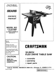
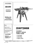
owners
manual
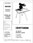
MODEL NO.
113.241591
SAW WITH LEGS
TWO CAST IRON
TABLE EXTENSIONS
MOTOR AND
HOLD DOWN CLAMP
L
Serial
Number
#
Model and serial
number may be found
at the rear of the base.
You should record both
model and serial number
in a safe place for
future use.
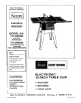
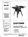
DELUXE
IO-INCH
FLEX DRIVE TABLE
SAW
CAUTION:
READ
. assembly
ALL
INSTRUCTIONS
. operating
CAREFULLY
= repair
Sold by SEARS,
ROEBUCK
AND
parts
CO.,
Chicago,
IL. 60684
U.S.A.
PriP,_:ed _n U_
Part No. 62965
i
_
..............
FULL ONE YEAR WARRANTY
ON CRAFTSMAN
,.
i
TAB LE SAW
If within one year from the date of purchase, this Craftsman Table Saw fails due to a defect in
material or workmanship, Sears will repair it, flee of charge.
WARRANTY SERVICE IS AVAILABLE BY SIMPLY CONTACTING
THE NEAREST SEARS
SERVICE CENTER/DEPARTMENT
THROUGHOUT
THE UNITED STATES.
This warranty applies only while this product is in use in the United States.
This warranty gives you specific legal rights, and you may also have other rights which vary
from state to state.
SEARS, ROEBUCK
GENERAL
AND CO.. Dept. 698/731A,
Sears Tower,
SAFETY iNSTRUCTIONS
1. KNOW YOUR POWER TOOL
Read and understand the owner's manual and
iabels affixed to the tool Learn its application
end imitations as well as the specific potential
hazards peculiar to this tool.
2. GROUND ALL TOOLS
This tool is equipped
with an approved 3conductor cord and a 3-prong grounding type
plug to fit the proper g rounding type receptacle.
The green conductor
in the cord is the
grounding wire. Never con nect the green wi re to
a live terminal.
Chicago, IL 60684
FOR POWER TOOLS
Z87.1) at all times. Everyday eyeglasses only
have impact resistant lenses, they are NOT
safety glasses. Also, use face or dust mask if
cutting operation is dusty, and ear protectors
(plugs or muffs) during extended periods of
operation.
13. SECt.iRE WORK
Use clamps or a vise to hold work when
practical. It's safer than using your hand, frees
both hands to operate tool.
14. DON'T OVERREACH
Keep proper footing and balance at all times.
3, KEEP GUARDS IN PLACE
in working order, and in proper adjustment and
alignment.
4. REMOVE ADJUSTmNG KEYS
AND WRENCHES
Form habit of checking to see that keys and
adjusting wrenches are removed from too_
before turning it on.
5. KEEP WORK AREA CLEAN
Cluttered areas and benches invite accidents,
Floor must not be slippery due to wax or
sawdust.
6. AVOID DANGEROUS ENVIRONMENT
Don't use power tools in damp or wet locations
or expose them to rain. Keep work area well
lighted. Provide adequate surrounding work
space.
7. KEEP CHILDREN AWAY
All visitors should be kept a safe distance from
work area,
15. MAINTAIN TOOLS WITH CARE
Keep tools sharp and clean for best and safest
performance. Follow instructions for lubricating
and changing accessories.
16. DISCONNECT
TOOLS
before servicing; when changing accessories
such as blades, bits, cutters, etc.
17. AVOID ACCIDENTAL STARTING
Make sure switch is in "OFF" position before
plugging in
18. USE RECOMMENDED
ACCESSORIES
Consult the owner's manual for recommended
accessories.
Follow
the instructions
that
accompany
the accessories.
The use of
improper accessories may cause hazards.
19. NEVER STAND ON TOOL
Serious injury could occur if the tool is tipped or
if the cutting tool is accidentally contacted.
Do not store materials above or near the tool
such that it is necessary to stand on the tool to
reach them.
8. MAKE WORKSHOP CHILD-PROOF
-- with padlocks, master switches, or by
removing Starter keys.
S, DON'T FORCE TOOL
Iw
t will do the job better and safer at the rate for
hich it was designed,
)r other
carefully
and
all
guard
11. WEAR PROPER
PPAREL
Do not wear Ioo
clothing; gioves, neckties or
jewelry (rings, _ St watches)to get caught in
nnovihg
part
N0nslip
footwear
is
recommended. Wear protective hair covering to
contain long hair. Roll long sleeves above the
elbow.
12. USE SAFETY GOGGLES (Head Protection)
Wear Safety goggles (must comply with ANS!
a
2
for
of moving
and any
.A
ADDITIONAL
SAFETY
iNSTRUCTiONS
WARNING: FOR YOUR OWN SAFETY, DO NOT
OPERATE YOUR SAW UNTIL IT IS COMPLETELY
ASSEMBLED AND INSTALLED ACCORDING TO
THE INSTRUCTIONS
... AND UNTIL YOU HAVE
READ AND UNDERSTAND THE FOLLOWING.
1. GENERAL
SAFETY INSTRUCTIONS
POWER TOOLS ... SEE PAGE 2
FOR
2. GETTING TO KNOW YOUR SAW... SEE PAGE
27.
3. BASIC SAW OPERATION...
SEE PAGE 30.
4, MAINTENANCE...
SEE PAGE 38.
5. STABILITY OF SAW
if there is any tendency for the saw to tip over or
move during certain cutting operations such as
cutting extremely large heavy panels or long
heavy boards, the saw should bebolted down.
If you attach any kind of table extensions over
24" wide to either end of the saw, make sure you
either bolt the saw to the bench or floor as
appropriate, or support the outer end of the
extension
from
the bench
or floor,
as
appropriate.
6. LOCATION
The saw should be positioned so neither the
operator nor a causal observer is forced to stand
in line with the saw blade.
FOR TABLE
operating immediately until the particular
part is properly repaired or replaced.
B. Small loose pieces of wood or other objects
that contact the rear of the revolving blade
can be thrown back at the operator at
excessive speed. This can usually be avoided
by keeping the guard and spreader in place
for all thru-sawing
operations
(sawing
entirely thru the work) AND by removing all
loose pieces from the table with a long stick
of wood IMMEDIATELY after they are cut off.
Use extra caution when the guard assembly
C. is removed for resawing, dadoing, rabbeting,
or molding
replace the guard as soon as
that operation is completed.
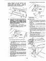
D. For rip or rip-type cuts, the following end of a
workpiece to which a push stick or push
board
is applied
must
be square
(perpendicular
to the fence) in order that
feed pressure applied to the workpiece by
the push stick or block does not cause the
workpiece to come away from the fence, and
possibly cause a kickback.
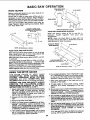
E. During rip and rip type cuts. the workpiece
must be held down on the table and against
the fence with a push stick, push block, or
featherboards.
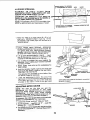
A featherboard
is made of
solid lumber per sketch.
]_
7. KICKBACKS
A "KICKBACK"
occurs during a rip-type
operation when a part or all of the workpiece _s
thrown back violently toward the operator.
Keep your face and body to one side of the
sawblade, out of line with a possible "Kickback."
Kickbacks
and possible injury from them
can usually be avoided by:
A. Maintaining the rip fence parallel to the
sawblade.
B. Keeping the sawblade sharp. Replace or
sharpen anti kickback pawls when points
become dull.
C. Keeping sawblade guard, spreader, and
antikickback pawls in place and operating
properly. The spreacler must be in alignment
with the sawblade and the pawls must stop a
kickback once it has started,
Check their action before ripping.
D. NOT ripping work that is twisted or warped
or does not have a straight edge to guide
along the rip fence.
E. NOT releasing work until you have pushed it
all the way past the sawblade.
F. Using a push stick for ripping widths of 2 to 6
in, and an auxi iary fence and push block for
ripping widths narrower than 2 in. (See
"Basic Saw Operation Using The Rip Fence"
section.)
G, NOT c6nfining the cut-off piece when
24'"
5/16"
I
AP_T
-5"'--.-.1
F. NEVER turn the saw "ON" before clearing
the table of all tools, wood scraps, etc.
except the workpiece and related feed of
support devices for the operation planned.
G. NEVER place your face or body in line witf"
the cutting tool.
H. NEVER place your fingers or hands in the
path of the sawblade or other cutting tool.
I. NEVER reach in back of the cutting tool witl"
either hand to hold down or support th_
workpiece, remove wood scraps, or for an_
other reason. Avoid awkward operations anc
J.
K.
L.
section of the workpiece between the saw
blade and the rip fence
8. PROTECTION:
EYES, HANDS, FACE, EARS,
BODY
A. If any part of your saw is malfunctioning, has
been damaged or broken..,
such as the
motor switch, or other operating control, a
safety device or the power Cord...
cease
SAWS
M.
hand
coulc
cause positions
fingers where
or handa suddenmovS_lPinto"
to
sawbtade or other cutting tool.
DO NOT perform layout, assembly, or setu_
work on the table while the cutting toot i,'
rotating.
DO
NOT
perform
any
operatior
"FREEHAND" -- always use either the ri[;
fence or the miter gauge to position ant
guide the work.
NEVER use the rip fence when crosscuttin_
.....
miter gauge when ripping. DO NO!
use the rip fence as a length stop.
Never hold onto or touch the "freeend"of the
workpiece or a "free piece" that is cut off
while power is "ON" and/or the sawbiade i,.
rotating.
Shut "OFF" the saw and disconnect
th_
power cord when removing the table insert
changing the cutting tool, removing ot
replacing the blade guard, or makin{;
adjustments.
when ripping, use the maximum diameter blade
f0 r which the saw is designed, since under these
conditions the spreader ts nearest the blade
N. Provideadequatesupportto the rear and
sides of the saw table for wider or long
workpieces.
O. Plastic and composition (like hardboard)
materials may be cut on your saw. However,
since these are usually quite hard and
slippery, the antikickback pawls may not
stop a kickback.
Therefore,
be especially
attentive
to
following
proper set-up
and cutting
procedures for ripping Do not stand, or
permit anyone else to stand, in line with a
potential kickback
P. If you stall or jam the sawblade in the
workpiece, turn saw "OFF", remove the
workpiece from the sawblade and check to
see if the sawblade is parallel to the miter
gauge grooves and if the spreader is in
proper alignment with the sawblade. If
ripping at the time, check to see if the rip
fence is parallel with the sawblade. Readjust
as indicated.
Q. DO NOT remove small pieces of cut-off
material that may become trapped inside the
blade guard while the saw is running. This
could endanger your hands or cause a
kickback. Turn saw "OFF" and wait until
blade stops.
R. Use extra care when ripping wood that has a
twisted grain or is twisted or bowed
it may
rock on the table and/or pinch the sawblade.
9. KNOW YOUR CUTTING TOOLS
A. Dull, gummy, or improperly sharpened or set
cutting tools can cause material to stick, jam,
stall the saw, or kickback at the operator.
Minimize potential injury by proper cutting
tool and machine maintenance.
NEVER ATTEMPT TO FREE A STALLED
SAWBLADE WITHOUT
FIRST TURNING
THE SAW OFF.
B. Never use grinding wheels, abrasive cut-off
wheels, friction
wheels (metal slitting
blades) wire wheels or buffing wheels.
10. USE ONLY ACCESSORIES
DESIGNED FOR
THIS SAW.
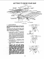
11. Crosscutting operations are more conveniently
worked and with greater safety if an auxiliary
wood facing is attached to the miter gauge using
the holes provided. However, the facing must
not interfere with the proper functioning of the
sawblade guard.
12. Make sure the top of the arbor or cutting tool
rotates toward you when standing in normal
operating position. Also make sure the cutting
t0ol, arbor collars and arbor nut are installed
properly.
Keep the cutting tool as low as
_)osstble for the operation being performed
14. Adjust table inserts flush with the table top.
NEVER operate the saw unless the proper insert
is installed.
15. NEVER feed material into the cutting tool from
the rear of the saw. An accident and serious
injury could result.
17. NEVER use another person as a substitute for a
table extension, or as additional support for a
workpiece that is longer or wider than the basic
saw table, orto assist in feeding or supporting or
pulling the work piece.
DO NOT pu the workpiece through the
sawblade - position your body at the nose (infeed) side of the guard: start and complete the
cut from the same side. This will require added
table support for long or wide workpeices that
extend beyond the length or width of the saw
table.
18. THINK SAFETY.
Safety is a combination
sense and alertness at all
being used.
19. NOTE AND FOLLOW
TIONS THAT APPEAR
YOUR SAW.
READ
I
AND
UNDERSTAND
OWNERS
$AWI_DE
KEE_
USE
GUARO
I DANGER
i4ANDS
OUT
A "PUSH.ST_CK"
WARNING:
OF
FOR
PATH
WHEN
"[
HRU-SAWIN
OF
SAW.LADE.
SAFETY INSTRUCON THE FRONT OF
MANUAl.
wrc_RSAFETYGOGGLES.
USE
of operator common
times when the saw is
G."
BEFORE
S,
KNOWHOWTO
6,
DO
7.
NEVER
NOT
OPERATING
REACH
MACHINE.
_VOtD"KICKIBACKS."
PERFORM
OPERATIONS
AROUND
OR
"PREEHANO,"
OVER
I FOR YOUR OWN SAFETY:
$AWBLADE,
REQUfRIEID*
uSElze VOLT t5 ,_P
SP.NCR CIRCUITA_O USE ISAMP TIME BELAYFUSE
20. WARNING: DO NOT ALLOW FAMILIARITY
(GAINED FROM FREQUENT USE OF YOUR
SAW)
TO BECOME
COMMONPLACE.
ALWAYS REMEMBER
THAT A CARELESS
FRACTION OF A SECOND IS SUFFICIENT TO
INFLICT SEVERE INJURY.
NOTE: Do not overtighten arbor nut. Use the arbor
.wrench to just "snug" it.
WEAR
YOUR
The operation of any power tool can result in foreign
MOTOR
SPECIFiCATiONS
This saw is designed to use a
Do not use any motor that
RPM. It is wired for operation
Hz., Alternating
current.
CONVERTED TO OPERATE
AND ELECTRICAL
3450 RPM motor only.
runs faster than 3450
on 110-120 volts, 60
IT MUST NOT BE
ON 230 VOLTS.
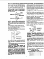
The Black and Red motor leads are connected to
quick connect tabs "A" and "B" on terminal board.
WARNING: Do not change any of these connections with current on.
TS
POWER LEAD
BLACK
REW
REQUIREMENTS
This saw is equipped with a 3-conductor cord and
grounding type plug which has a grounding prong,
approved by Underwriters'
Laboratories
and the
Canadian Standards
Association.
The ground
conductor has a green lug and is attached to thetool
housing at one end and to the ground prong in the
attachment plug at the other end.
This plug requires a mating 3-conductor grounded
type outlet as shown.
If the outlet you are planning to use for this saw is of
the two prong type DO NOT REMOVE OR ALTER
THE GROUNDING PRONG iN ANY MANNER. Use
an adapter as shown and always connect the
grounding lug to a known ground.
it is recommended
that you have a qualified
electrician replace the TWO prong outlet with a
properly grounded THREE prong outlet.
PowE.LEAD'--'
CAUTION: Oo not use blower or washing machine
motors or any motor wifh an automatic reset
overload protector as their use may be hazardous.
For replacement motor refer to parts list in this
manual.
CONNECTING TO POWER SOURCE OUTLET
This saw must be grounded while in use to protect
the operator from electrical shock.
If power cord is worn or cut, or damaged in any way,
have it replaced immediately.
If your saw is for use on less than 150 volts it has a
plug that looks like below.
3-PRONG
/n
I
gt
t_
A temporary adapter as illustrated is available for
connecting
plugs to 2-prong receptacles.
The
temporary adapter should be used only until a
properly grounded outlet can be installed by a
qualified electrician.
GROUNDING
WARNING:
THE GREEN GROUNDING
LUG
EXTENDING
FROM THE ADAPTER MUST BE
CONNECTED
TO A PERMANENT
GROUNE
SUCH AS TO A PROPERLY GROUNDED OUTLE1
BOX. NOT ALL OUTLET BOXES ARE PROPERL_
GROUNDED.
\
GROUNDING
PRONG
PROPERLY
GROUNDED
LUG
ADAPTER
PLUG
/,DI
0
A temporary adapter as shown below is available for
connecting plugs to 2-prong receptacles. The green
grounding lug extending from the adapter must be
connected to a permanent ground such as to a
properly grounded outlet box.
I.
3*PRONG
OUTLET
Plug power cord of fully assembled saw into 110120V properly grounded type outlet protected by a
15-am p. time delay or Circuit-Saver fuse or circuit
breaker.
IF YOUR ARE NOT SURE THAT YOUR OUTLET IS
PROPERLY GROUNDED, HAVE IT CHECKED BY
A QUALIFIED ELECTRICIAN.
WARNING:
DO NOT PERMIT FINGERS TO
TOUCH
THE TERMINALS
OF PLUG WHEN
INSTALLING OR REMOVING THE PLUG TO OR
FROM THE OUTLET.
WARNING: IF NOT PROPERLY GROUNDED THIS
POWER TOOL CAN INCUR THE POTENTIAL
HAZARD OF ELECTRICAL SHOCK PARTICULARLY WHEN USED IN DAMP LOCATIONS, IN
PROXIMITY TO PLUMBING, OR OUT OFDOORS.
SUCH AS YOUR
SAWBLADE.
HANDS
CONTACTING
THE
If you are not sure that your outlet box is properl_
grounded, have it checked by a qualified electrician
NOTE: The adapter illustrated is for use only if yoL
already
have a properly
grounded
2-pron_
receptacle.
The use of any extension cord will cause some los,'
of power. To keep this to a minimum and to preven
over-heating and motor burn-out, use the tab!_
below to determine the minimum wire size (A.W.G.
extension cord, Use only 3 wire extension cord,,
which have 3 prong grounding type plugs and 3.
pole receptacles which will accept the plug on th_
SBW.
The motor must rotate COUNTERCLOCKWISI
when viewed from the shaft end.
1 H,P. MOTOR 110-120V
Extension Cord Length
Wire SIze A.W.G.
Up to 50 Ft.................
14
50 to 100 Ft................
12
100- 200 Ft................
10
200 - 400 Ft .................
8
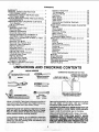
CONTENTS
WARRANTY
.................................
2
GENERAL SAFETY INSTRUCTION
FOR POWER TOOLS ......................
2
ADDITIONAL SAFETY INSTRUCTIONS
FOR TABLE SAWS ........................
3
MOTOR SPECIFICATIONS
AN D ELECTRICAL
REQUIREMENTS
..........................
5
UNPACKING ANC CHECKING CONTENTS
.. 6
Tools Needed .............................
6
List of Loose Parts .........................
7
ASSEMB L.Y ..................................
9
Assembling Steel Legs .....................
9
Mounting Saw .............................
9
Installing Handwheels .....................
10
Checking Table Insert .....................
10
Heeling Adjustment of Parallelism of
Sawblade to Miter Gauge Groove .........
11
Blade Tilt, or Squareness of Blade to Table
12
Tilt Mechanism ...........................
14
Mounting The Motor ......................
14
Mounting The Flexible Shaft ...............
15
Attaching Table Extensions
...............
18
Aligning Extensions .......................
19
Mounting Switch ..........................
19
Installing Rip Fence Guide Bars ...........
19
Aligning Rip Fence ....................
21
Adjusting Rip Scale Indicator ..............
23
Installing Blade Guard ....................
23
Aligning Spreader
........................
25
Adjusting Miter Gauge ....................
25
Assembling Hold-Down
...................
26
Plugging in the Motor .....................
26
GETTING TO KNOW YOUR SAW ...........
27
On-Off Switch .........................
27
UNPACKING
Elevation Handwheet ......................
Tilt Handwheel
...........................
Tilt Lock Handle ..........................
Rip Fence ................................
Miter Gauge ..............................
Blade Guard ..............................
"Fable Insert ...... "........................
Removing and Installing Sawblade .........
Exacti-Cut ................................
BASIC SAW OPERATION USING THE MITER
GAUGE
Work Helpers .............................
Crosscutting
..............................
Repetitive Cutting .........................
Miter Cutting
.............................
Bevel Crosscutting
........................
Compound Miter Cutting ..................
BASIC SAW OPERATION USING THE RIP
FENCE ...................................
Ripping
..................................
Bevel Ripping
............................
Ploughing and Molding ...................
Resawing .................................
Cutting Panels ............................
Rabbeting
................................
Dadoing ..................................
Using Featherboards ......................
MOTOR ....................................
MAINTENANCE
............................
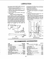
LUBRICATION
.............................
RECOMMENDED
ACCESSORIES
...........
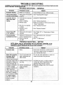
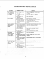
TROUBLE SHOOTING ......................
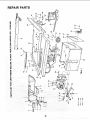
REPAIR PARTS .............................
AND CHECKING
STRAIGHT
3/4"
Medlumsmall
ScrewdrlverSCrewdrlver
DRAW LIGHT
BOARD
ALONG
LINE
THIS
ON
EDGE,
"_ BE
_, \_
i_j
SHOULD
Wrenches
i
EDGE
OF
THIS
EDGE
PERFECTLY
BOARD
MUST
STRAIGHT.
I f
Mlere
Sq-are
THICK.
\i l-
#2 Phillips Screv_ldver
CombP"Uon
33
33
33
35
36
36
36
37
37
38
38
39
39
40
42
SQUARE MUST BE TRUE.
_
Hammer
30
31
31
32
32
33
CONTENTS
COMBINATION
TOOLS NEEDED
;_"_-J_-_
28
28
28
28
28
28
28
29
29
j
BE NO GAP OR OVERLAP
HERE
SQUARE
OVERWHEN
IN DOTTED
IS FLIPPED
POSITION.
'7
............
•....................... rt
Separate al parts from packing mat
each one with the illustration and t
Parts to make certain all items are
before discarding any packing rnai
riai
re ii
acc
rial
plied to the table
any ordinary
spot remover.
health hazard never use
highly volatile solvents.
wax to the table.
, cloth.
NEVER
3E OUTLET
=.TE,
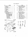
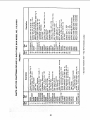
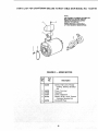
LIST OF LOOSE PARTS
item
A
B
C
D
E
F
G
H
J
K
L
M
N
0
P
Part Name
Blade Guard and Spreader ...........
Rip Fence ..........................
Owners Manual .....................
Miter Gauge ........................
Rod, Separation (Fence) .............
Leg ................................
Stiffener, End .......................
Stiffener, Side
Handwheel .........................
Extension, 12 x 27 ...................
Motor ..............................
Motor Mount .......................
Shaft, Flexible ......................
Rip Fence Guide Bar with Rip Scale ...
Rip Fence Guide Bar, Rear ............
Loose Parts Bag ....................
(Containing the following items):
Loose Parts Bag No. 62752 .......
Loose Parts Bag No. 62890 .......
Loose Parts Bag No. 62951
....
Loose Parts Bag No. 62891 .......
O Outlet, On/Off ................
R Key, Switch .................
S Wrench, Arbor ...............
T Bracket, Shaft ...............
U Support, Spreader ...........
Qty,
1
1
1
1
1
4
2
2
2
2
1
1
1
1
1
t
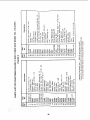
Item
1
1
1
1
1
t
1
2
1
Qty.
1
A
B
B
C
C
C
D
E
F
Part Name
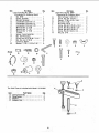
Loose Parts Bag No. 62752 for Legs ...
(Containing the Following Items):
Screw, Truss Hd.Ji4-20 x 5/8 ....
Lockwasher, External 1/4 ........
Lockwasher, External 5/16 .......
Nut, Hex 1/2-13 .................
Nut, Hex 1/4-20 .................
Nut, Hex 5/16-18 ................
Screw, Hex 5/16-18 x 1-1/4 ......
Washer, 11/32 x 11/16 x 1/16 ....
Foot, Leveling ..................
1
B
B
B
C
C
D
E
E
E
G
H
H
J
Loose Parts Bag No. 62890 ...........
(Containing the Following Items):
Lockwasher, External #10 ........
Lockwasher, External 114 ........
Lockwasher, External 5116 .......
Nut, Hex 1/4-20 .................
Nut, Hex 5/16-18 ................
Screw, Hex Hd. 1/4-20 x 1 .......
Washer, 21/64 x 5/8 x 1/16 ......
Washer, 17/64 x 3/4 x 1/16 ......
Washer, 21/64 x 47/64 x 1/16 ....
Screw, Pan Hd. Type T 10-32 x 3/8
Bolt, Carriage 1/4-20 x 3/4 .......
Bolt, Carriage 5/16-18 x 3/4 ......
Nut, Hex Jam 5/16 x 18 ..........
¢
G
T
G
U
7
24
24
4
8
24
4
4
8
4
3
6
4
6
8
2
2
2
4
3
4
4
2
Item
A
B
C
D
D
D
E
E
E
F
G
H
J
K
L
M
Part Name
Loose Parts Bag No. 62951 ...........
(Containing the Following Items):
Nut, Weld ......................
Clamp Spreader ................
Bracket, _;preader ..............
Lockwasher, External 1/4 ........
Lockwasher, External #10 ........
Lockwasher, External 5/16 .......
Wrench, Hex "L" 3/32 ...........
Wrench, Hex "L" 1/8 ............
Wrench, Hex "L" 5/32 ...........
Tie Wire ......................
Spacer, Fence Guide Bar .........
Nut, Self-Threading
..........
Screw, Hex Hd.5/16-18 x 1-1/4 ...
Nut, Hex Jam 5/16-18 ...........
Connector. Motor ...............
Washer 11/32 x11/16 x1/16
....
Qty.
1
Item
1
1
1
6
2
14
1
1
1
2
2
2
8
8
1
8
A
B
C
D
E
F
F
F
G
H
PartName
Loose Parts Bag No. 62891 ...........
(Containing the Following Items):
Bolt. Carriage 1/4-20 x 3/4 .......
Screw, Soc. Set 1/4-20 x 1 .......
Washer. 17/64 x 9/16 x 3/64 .....
Nut, Hex 1t4-20 .................
Nut, Wing 1/4-20 ................
Screw, Hex Hd. 5116-18 x 1-3/4 ...
Screw, Hex Hd. 5/16-18 x 3/4 ....
Screw, Hex Hd. 5/16-18 x 1 ......
Screw, Pan Hd. 10-32 x 3/4 .......
Key, Sq. 3/16 ...................
C
A
A
B
C
D
D
E
G
F
G
H
F
M
K
The Hold Down is included
Item
A
B
C
D
with Model 113,241691
Part Name
ClampAssembly
....................
Wing Screw .........................
Washer .............................
Support Rod ........................
Qty.
1
2
2
1
8
Qty.
1
4
2
4
4
2
2
2
2
2
1
E
H
ASSEMBLY
o
ASSEMBLING
STEEL LEGS
NOTE: Steel Legs are furnished
with Model
113.241691, From among the loose parts, find the
following Hardware:
24 Truss Head Screws, 1/4 - 20 x 5/8 in. long (top
of screw is rounded)
24 Lockwashers. 1/4 in. External Type (approx.
dia. of hole 1/4 in.)
24 Hex Nuts, 1/4 - 20 (approx, dia. of hole 1/4 in.)
8 Hex Nuts, 1/2 - 13 (approx. dia. of hole 1/2 in.)
4 Leveling feet.
Assemble the legs as shown ...
1. Insert the Truss Head Screws through the holes
in the legs, then through the holes in the
stiffeners. MAKE SURE THE SCREWS GO
THROUGH
THE
HOLES
IN THE
SIDE
STIFFENERS MARKED "X".
ASSEMBLE
THROUGH
MARKED"X"
J"
7
-/f
"_,SIDE
SCREWS
HOLES
STIFFENER
END
STIFFENER"
2. Install the Iockwashers,..
screw on the nuts but
Do Not tighten until completely assembled.
_21N. HEX
3, Install leveling feet.
MOUNTING
SAW
1. From among the loose parts, find the following
hardware:
4 Hex Head Screws, 5/16 - 18 x 1-1/4 in. long.
4 Hex Nuts, 5/16 - 18 (approx. dia. of hole 5/16 in.)
4 Lockwashers, 5/16 in. External Type (approx,
dia. of hole, 5/16 in.)
8 Flat Washers, (dia. of hole 11/32 in.)
2. Place saw on legs so that holes in bottom of saw
line up with holes in top of legs.
/
/
/
SAW
HEX HEAD SCREW
FLAT
3, install screws, washers,
shown.
Iockwashers
BASE
_,_l
I
WASHER
and nuts as
END
STIFFENER-'I
;
'I
NUTS
11,1/4
1
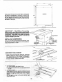
If you mount the saw on any other bench, make sure
that there is an opening in the top of the bench the
same size as the opening =nthe bottom of the saw so
that the sawdust can drop through. Recommended
working height is 33to 37 inches from the top of the
saw table to the floor.
OPENING
16"3/4"
15,1
@
7116"
FRONT
IMPORTANT
-- Read Before
Ot:
DIA,
HOLES--_
--_
SAW
Proceeding
Blade cannot be more than 2 inches above the table
top when tilting the sawblade to make bevel cuts or
adjustments, Lower blade to 2 inches or closer to
the table top to tilt the saw, Failure to do this may
result in damage to your saw.
.OCKWASHER
/
/
INSTALLING
HANDWHEELS
Line up FLAT SPOTS on shaft and handwheel, push
handwheel onto shaft. Install screw and Iockwashe r
to lOck handwheels on shaft.
10-32 x 3/4 IN.
PHILLIPS
HEAD SCREW
ELEVATION
HANOWB
TILT HANDWHEEL
//
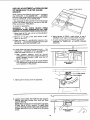
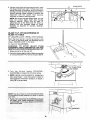
CHECKING
TABLE
INS ERT
1. Insert should be even with table top. Check as
shown. Loosen flat head screw that holds insert
and adjust the four set screws as necessary,
Tighten flat head screw. Do not _ighten screw to
the point where it deflects the insert.
3/32
SETSCREW
IN
WRENCH
2. To remove insert.
A. Loosen Phillips Flat Head Screw.
B: Lift insert from front end, and pull toward front
of saw.
3. To replace insert:
Place insert into insert opening in table and push
toward rear of sawto engage spring clip and until
keyslot in insert w ! drop over screw T ghten
screw.
Do not tighten screw to the point where it will
deflect the insert.
/
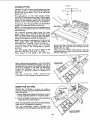
HEELING ADJUSTMENT
or PARALLELISM
OF SAWBLADE TO MITER GAUGE
GROOVE
MARK'X"ON
TOOTH
While cutting, the material must move in a straight
line PARALLEL to the SAWBLADE . . . therefore
both the miter gauge GROOVE and the RIP FENCE
must be PARALL:EL to the SAWBLADE,
If the sawblade IS NOT parallel to the miter gauge
groove, the blade will bind at one end of the cut.
(This is known as "HEELING").
To check for parallelism:
WARNING
-TO AVOID
INJURY
FROM
ACCIDENTAL START, TURN SWITCH "OFF" AND
REMOVE PLUG FROM POWER SOURCE OUTLET,
1. Raise blade all the way up by turning
handwheel clockwise,
elevation
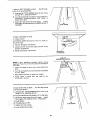
4. Move square to REAR, rotate blade to see if
MARKED tooth again touches blade of square.
2. Mark an "x" on one of the teeth which is SET
(bent) to the LEFT.
3. Place the head of a combination square in the
GROOVE... adjust blade of square so that it just
touches the tip of the MARKED tooth.
5. If tooth touches square at FRONT and REAR.
sawblade is PARALLEL to MITER GAUGE
GROOVE.
6. If tooth does not touch the same amount..,
the
mechanism underneath
must be adjusted to
make the blade PARALLEL to GROOVE.
o
A. Rear support
bearing
must be moved
TOWARD the combination square if there is a
space between marked tooth and end of
square in step 4.
B. Rear support bearing must be moved AWAY
from the square if marked tooth pushes square
out of position i_ the groove.
/
REAR SUPPORT
BEARING
I
o
c,A'.,
sc.E -
7. Make sure tilt clamp screw is tightened.
"-L_F
8. Loosen both screws that hold the rear support
bearing and both screws that hold the front
support bearing,
NOTE; Rear screws can be reached through back
of saw. Use a 9/16-in. wrench. To reach front
support bearing screws insert open end wrench
through opening in front of base by the tilt clamp
screw.
'
"_L
_-_=J
-'_
BEARING
il
_-
WOOD
• 9. Using a wood block and hammer as shown, move
rear support bearing to right or left as req ui red to
realign the blade. If necessary, shift front support
bearing in similar manner; butdo NOT move front
support bearing unless necessary, Recheck the
alignment
with the square,
then securely
retighten all support bearing screws.
BLOCK
/
NOTE: Be certain that the widest blade you use
does not contact
blade insert after moving
support
bearing.
Check
this at both
0°
(perpendicular
to the table) and 45 ° bevel by
rotating
the fully elevated blade by hand.
Readjust as required to maintain sufficient
clearance.
BLADE
BLADE
TILT, OR SQUARENESS
TO TABLE
OF
90 ° (SQUARE) and 45 ° (BEVEL) STOP SCREWS.
When the bevel pointer is pointing directly to the
"O" mark on the bevel scale, the sawblade should
make a SQUARE cut 90 ° to the table.
To check for SQUARENESS:.
WARNING:
TO AVOID
INJURY
FRONt
ACCIDENTAL START, TURN SWITCH "0 FF" AND
REMOVE PLUG FROM POWER SOURCE OUTLET,
1. Blade should be all'the way UP.
2. Place the square against blade. Make sure square
is nottouching
the TIP of one of the saw TEETH
O
"_J/__--TILT
-
CLAMP
,,_"
_"_TILT
LOCK
I'IAN[)LE
3. Turn
the tilt-lock
handle
(COUNTER-CLOCKWISE) to loosen the tilt clamp screw.
4. NOTE: Handle is spring loaded for engagement
with screw head -- must be pushed inward for
disengagement whenever necessary to obtain a
new grip on screw head.
//
12
SCREW
\
If blade is NOT SQUARE to table
screw must be ADJUSTED.
A. Unscrew 90° STOP SCREW three to four turns
using 3/16 in setscre.w wrench.
B. Turn tilt handwheel clockwise oneturn, then turn
handwheel
counterclockwise
until blade is
square with table.
C. Screw 90 ° stop screw IN until it stops..,
check
once again for squareness and readjust screw, if
necessary.
If blade
is SQUARE
A. Check
B. Loosen
medium
C. Reinstall
/
/
!
\
i
\
O
90 °
STOPSCREW
J
to table:
\
\
1
pointer
IF POINTER
DOES
the bevel scale:
A. Remove
/
.. the 90° stop
NOT
Elevation
point
to the "O"
mark
on
2
Handwheel.
pointer
screw
screwdriver.
Elevation
and adjust
pointer
using
//
/
Handwheel.
/,
POINTER
AT
"0" POSITION
HEAD
COMBINATION
OF
SQUARE
NOTE:
Lower
sawblade
elevation
before
tilting
sawblade. Failu re to do this may result in damage to
your saw.
1. Lower the blade to about two inches above the
table.
2. Turn tilt handwheel
to a 45 ° bevel.
counterclockwise
3. Raise blade elevation
to maximum
4. Check
bevel of blade
combination
square.
with
If blade is NOT 45 ° to table..,
must be ADJUSTED.
the
until
blade
height.
head
of
the
/
the 45 ° stop screw
A. Unscrew 45 ° STOP SCREW three
using 3/16 in. setscrew wrench.
B. Turn tilt handwheel
to tilt blade
to four
turns
7. Tighten
8. Lower
tilt lock
blade
is45 ° to the table.
\
to 90 ° .
handle.
below
\
/
C. Screw 45 ° stop screw IN until it stops..,
check
once again and readjust screw, if necessary.
5 Lower blade;
6. Tilt blade back
---k
table.
13
\
\
TiLT MECHANISM
Lower blade to 2 inches or closer to the table top
before tilting
blade. Failure to do this may result in
damage to your saw.
TILT
HANDWHEEL
The handwheel should turn freely without binding.
The turn ing action can be adjusted by tightening or
loosening the screws in the bearing retainer.
_J
NOTE: Tilt Handwheel must be removed to adjust.
When adjusting the screws in the bearing retainer
using a screwdriver, hold the nut inside using a 3/8
in. wrench.
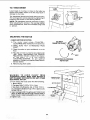
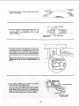
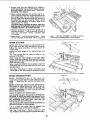
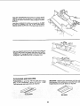
MOUNTING
THE
ADJUST
THESE
TWO SCREWS
MOTOR
1. CHECK MOTOR ROTATION
A. The motor
CLOCKWISE
must rotate
COUNTER-when viewed from the shaft end.
B. MAKE SURE "'KEY"
SHAFT,
IS REMOVED
C. Place the motor on your workbench
floor.
DIAMETER
SHAFT
FROM
5/8 INCH
or on the
(f
D. Plug the cord into a properly grounded outlet
(See "Motor
Specifications
and Electrical
Requirements"
Section.) Notice the rotation
of
the
shaft.
If it is not
turning
COUNTERCLOCKWISE,
do not continue
assembly, Contact your nearest Sears Store or
Service Center.
_,._
COUNTER-CLOCKWISE
ROTATION
E. Remove plug from outlet.
14
_"_"
KEY
THESE
TWO EDGES_EVEN
__
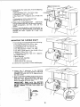
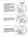
5. Fromamongthe looseparts,find thefollowing
hardware:
4 CarriageBolts,5/16- 18×3/4 in, long
4 Flatwashers17/64x 3/4x 1/16
4 Hex.Nuts,5/16- 18(approx,dia.of ho_e5/16
in.)
4 Lockwashers.
5/16in. ExternalType
(approx.alia.of hole5/t6 n.)
6. #lacemotoron MOTORMOUNT... insertbolts
throughholesin MOUNTthen
throughthemotor.
Install Iockwashers.and hex. nuts. Do not
tighten.
7. PositionMOTORBASEon MOTORMOUNTso
theedgesofthe MOTORBASEandtheMOTOR
MOUNTare even. Tighten all 4 Hex. nuts
securely.
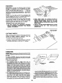
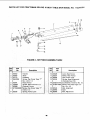
MOUNTING
THE
FLEXIBLE
SHAFT
1. From among the loose parts find the following:
3 Pan Head Screws 8-32 x 3/8 in. long
3 Lockwashers Externat Type No. 8
2 Carriage Bolts 1/4 - 20 x 3/4 in. long
2 Hex Head Screws 1/4-20 × 1 in. long
4 Hex Nuts 1/4-20 (approx. dia. of hole 1/4 in.)
2 Washers 17/64 x 3/4 x 1/16
4 Lockwashers External Type 1/4 in. (approx.
alia. of hole 1/4 in.)
2 Shaft Brackets
1 Flexible Shaft Assembly
1 Motor Connector
1 Square Key 3/16 x 5/8 long
2. Install 3/16 in. square key in motor shaft keyway.
Loose.
t.o2setscrews
.he.OTO.
3. CONNECTOR. Line up the keyway in MOTOR
CONNECTOR with the 3/16 in. square key on
_-_-_-nr_.___
i tl
t.eo,or
4. SlidetheMOTOROONNECTORontothemotor
Ill
II!
__
I I_-------_
f _'_l..=..__----------_t
/_
_/ _-"_
shaft as far as it will go. SECURELY tighten 2
setscrews. Test setscrews by trying to slide
motor connector off motor shaft.
CONNIECTOR is puslted on the shaft as far as it
/1/ ""_,_¢ _
_._,,So.
€,pp,o=
_8,.o,,,ore
too,o,
..,
IL_
=
j i_f
£z"'I--"_---_----_
3/8 INCH
_5
_f-_!
i
J
I t! °l !
I1t
I
k-\
I
{
I It
\\
I
I
t
I II
!li
_
--71i
I!l
SAW
MOTOR
5. Removethe plasticcoversfromthe endsof the
SHAFTHOUSING.
END
d
_ --.
ARBOR
END
6. Push the saw arbor end of the flexible shaft out
of the
SHAFT
HOUSING
until
it
is
approximately
1 inch above the end of the
SMALL FERRULE.
PULL FLEXIBLE
SHAFT
OUT 1"
©
SAW
ARBOR
END
L_[
O
7. Insert the flexible shaft assembly through the
opening in the side of the saw base. Line up the
SQUARE END of the FLEXIBLE SHAFTwith the
square hole in the arbor shaft, holding square
end of flexible shaft insert the FLEXIBLE SHA F]into the square hole in the arbor as far as it wil I
go.
IMPORTANT: Make sure the FLEXIBLE SHAFT is
inserted as far as it will go. Approximately 3/4
inch.
SHAFT
RETAINER
PAN HEAD SCREW
10-32 x 3/8 iN.
|6
CAREFULLY
ROTATE
BLADE
HAND TO LINE UP SQUARE
END OF FLEXIBLE SHAFT
WiTH
9. Bend the SHAFT HOUSING toward the motor
as illustrated, insert end of LARGE FERRULE
over MOTOR
CONNECTOR
and line up
SQUARE END of flexible shaft with square hoJe
in MOTOR CONNECTOR.
SQUARE
MOTOR
\
NOTF.: ff FLEXIBLE SHAFT is not properly
positioned in the square hole of the MOTOR
CONNECTOR it will not be Possible to make
this con nection. It may be necessary to carefully
rotate the blade to line up the SQUARE END of
the flexible shaft with the square hole in the
MOTOR CONNECTOR.
10. Push LARGE FERRULE as far as it will go
against the motor end cap. if it does not enter
motor end cap to ferrule bead, rotate saw blade
while pushing ferrule toward motorto permitthe
square ends of the core to enter their square
mating holes deep enough to allow ferrule to be
correctly positioned.
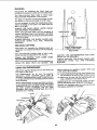
11. Assemble upper and lower shaft bracket by
inserting 1/4-20 x 3/4 carriage bolts in upper and
lower square holes on the saw base rear panel
and then through the slotted hole in the shaft
brackets. AssembJe 17/64 x 3/4 x 1/16 washer,
External Type Lockwasher, and 1/4-20 Hex Nut.
Finger tighten.
12. POsition the upper and lower shaft brackets so
they wrap around the LARGE FERRULE on the
SHAFT HOUSING. Bottom bracket should just
contact and support LARG E FERRULE. Tighten
nuts that hold the shaft b rackets to the saw base.
13. Assemble two 1/4-20 x 1 in. Hex Head Screws,
External Lockwashers, and !/4-20 Hex Nuts to
clamp upper and lower brackets together. Do.
not tighten.
17
HOLE
CONNECTOR
IN
BY
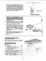
14. With end of LARGE FERRULE inserted into
recess in motor end cap tighten 2 Hex Head nuts
on shaft brackets. LARGE FERRULE must be
pushed against the motor end ca p as far as it wil I
go. Tighten nuts but do not OVERTIGHTEN.
The shaft brackets hold the LARGE FERRULE in
place. Nuts should be securely tightened to
prevent movement. Overtightening
may cause
damage to the LARGE FERRULE.
__
BEAD ON
CONTACT
FERRULE
MOTOR
MUST
END CAP
IMPORTANT: The LARGE FERRULE should be
centered over the MOTOR CONNECTOR (now
located Inside of LARGE FERRULE), to prevent
the MOTOR CONNECTOR from contacting the
LARGE FERRULE.
15. Carefully turn saw blade by hand to make sure
MOTOR CONNECTOR
does not hit LARGE
FERRULE.-If they are .in contact, it will cause a
noise and cause resistance to rotation,
16. If the MOTOR CONNECTOR
does hit the
LARGE FERRULE loosen the nuts holding the
shaft brackets to the saw base, and the nuts
holding
the LARGE FERRULE in the shaft
brackets. Adjust the brackets and the LARGE
FERRULE
until the LARGE
FERRULE is
centered
and is not hit by the MOTOR
CONNECTOR.
NOTE: It may be necessary to raise or lower
motor on motor mount slightly. Be sure to
reposition shaft brackets as required.
17. Tighten nuts.
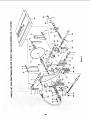
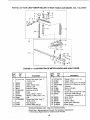
ATTACHING
AND ASSEMBLING
TABLE EXTENSIONS
From among the loose parts find the following
hardware: ((_uantity indicated is for 2 extensions)
HARDWARE FOR INSTALLING
EXTENSIONS TO SAW TABLE
Ref.
No. Description
Qty.
1 Hex Hd. Screw, 5/16-18 x 1-1/4 .... ..
8
2 Flat Washer (Dia. of Hole 11/32) .....
8
3 External Lockwasher, 5/16_ ...........
8
/
z
LARGE
FERRULE
MOTOR
CONNECTOR
MOVE
BRACKETS
UP OR
DOWN
SO THAT
MOTOR
CONNECTOR
INSIDE
DOES
NOT HIT FERRULE.
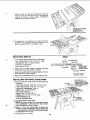
4. Line up front andtop of the extensionwith the
front and top of the table. Usea combination
square to line-up these edges. SLIGHTLY
TIGHTENnutswith a wrench.
CHECK WITH SQUARE
AT 2 PLACES
MARKED
WITH
"X"
ii
5. tf adjustment
_s necessary
you should tap the
extension
into position
using a hammer
and a
block of wood. Then firmly tighten
nuts.
BLOCK
OF WOOD
:
\
\
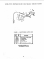
MOUNTING
JAM NUT
5/t6-18
SWITCH
1• From among loose parts find the following:
2 Hex Head Screws 5/16-18 x 3/4 in. long
2 Flatwashers (alia. of hole 21/64 in.)
2 External Lockwashers
2 Hex Nuts 5/!6-18
2. Insert two 3/4 inch screws through
washers then through holes in switch.
"_
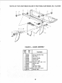
RiP FENCE
GUIDE
HOLE
two flat
%'_-'--
WASH
ER
t
HEX HEAD SCREW
5/16-18
x 3/4 IN.
BARS
1. From among the loose parts find the following
hardware:
2 Hex Plead Screws, 5/16-18 x 1-3/4 in. long
2 Hex Head Screws, 5/16-18 x 1 in. long
4 External Lockwashers, 5/16 in.
(approx. dia. of hole 5/16 in.)
4 Hex Nuts, 5/16-18
(approx. dia. of hole 5/16 in.)
2 SpaceFs, 3/4 in. dia. x !/2 in. long
2 Self-threading nuts
1 Fence Guide Bar Rod
7TH HOLE
3RD HOLE
LEFT SiDE OF
FRONT
GUIDE
BAR
(GUIDE
BAR IS TO BE
TURNED
END FOR END
AFTER
SCREWS
ARE
INSTALLED)
SCREW
5/16-18 x 1-3./4 IN.
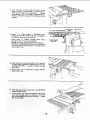
2. Lay guide bars on saw table,
NOTE: The various holes in the bar allows them
to be positioned on this saw and also makes
them adaptable to other models.
3. Insert a 1-3/4 inch long screw through the
THIRD hole IN THE FRONT BAR as illustrated
•.. Insert another 1-3/4 inch long screwthrough
the SEVENTH hole in bar.
4. Place spacers on screws.
/LOCKWASHER
@-_
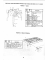
,8TH
w_
3. Insert screws through holes eight and ten in front
fence guide bar as illustrated•
4. Install two Iockwashers and nuts. Tighten nuts.
INSTALLING
8
19
5. Turn front bar end for end and insert bo}ts
through holes in middle and on right sides of
front of saw table as illustrated . . . install
Iockwashers and nuts. DON'T SCREW NUTS
ON ALL THE WAY. just get them started on the
screws.
4TH
_"
SELF-THREADING
NUT
OR
5TH
2ND
HOLE
HOLE
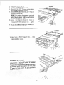
6. Insert 1 in. long screws in SECOND
and
FOURTH or FIFTH holes of rear bar and attach
to table the same way as front bar.
7. Insert ends of FENCE GUIDE BAR ROD
through holes in bars as illustrated.
NOTE; The ends of the RODare notthreaded,.
the SELF THREADING
NUTS will cut threads
on the rod as they are screwed on. Just start nuts
onto ends of rod.
FENCE
BAR
GUIDE
ROD
8. Hold rod with one hand and with a 1/2 in. wrench
or pliers start screwing on ONE of the nuts only
A TURN OR TWO...
screw on other nut the
same way.
9. Using TWO 1/2 in, wrenches or pliers tighten
both of the nuts,
.f
/
10. Slide the bars so that screws are in the M I DDLE
of the slotted holes,
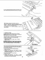
11. Lift rip fence lock lever and position rip fence
over miter gauge groove, holding up the rear
end while engaging front end witl-; bar..,
lower
fence onto table,
8 THICKNESSES
OF PAPER
12. Raise blade all the way up.
13. Carefully
move fence against
blade.
14. Move front bar until "0" mark on rip scale is
approximately
in line with indicator.
15. Move FRONT bar upwards
until fence is
approximately
1/32 in. above table..,
tighten
screw at left end of bar.
NOTE: Fold a piece of newspaper making 8
thicknesses and place between rip fence and
table to act as a spacer. This will ho_d the fence
off of the table approx. 1/32 in.
16. Adjust
rear bar so that
the fence
is
approximately 1/32 in. above table.., make sure
it is square with fence guide bar rod.., tighten
screw at end of bar.
17. Be sure top surface of extension is PARALLEL
to top surface of rear guide bar.
8THICKNESSES
OF PAPER
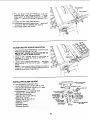
18. Move fence to RIGHT edge of table..,
make
sure it is approx. 1/32 i n. above table at front and
rear and tighten screws.
/
ALIGNING
RIP FENCE
The fence should side easily along the bars and
always remain in alignment
(para el to sawblade
and miter gauge grooves).
The alignment is rnaintained by a spring underneath
the rip fence which bears against the front guide
bar.
TO move the fence, loosen the lock handle and
grasp the fence with one hand at the front.
"_--_
For very close adjustments, grasp the guide bar with
both hands and move the fence with your thumbs.
\
Place fence on saw but DO NOT LOCK IT.
Move the REAR END of the fence slightly to the rig ht
or left . . . when you release it, the fence should
"spring" back to its original position.
If it does not, the spring pressure must be
INCREASED.
1. Loosen the screws.
2. Move Spring slightly toward front of fence.
NOTE: Applying a coat of paste wax to the rails will
allow fence to be moved more easily.
If the fence does not slide easily along the bars, the
pressure of the spring can be REDUCED.
1. Loosen the screws.
2. Move spring slightly toward rear of fence . . .
tighten screws.
SPRING
WARNING:
BE SURE TO PUSH LOCK LEVER ALL
THE WAY" DOWN UNTIL THE LEVER RESTS ON
THE STOP BEFORE USING THIS RIP FENCE.
SLIDE
ADJUST
SPRING
TO
PRESSURE
The rip fence lock lever when locked down should
hold the rip fence securely, it should not be difficult
to push down and lock.
If lock lever does not lock fence securely ....
1. Raise lock lever.
2. Tighten
the adjusting
nut using
a small
screwdriver until the lever, when locked, holds
the rip fence securely.
ff lock lever is difficult to push down ...
1. Raise lock lever_
2. Loosen the adjusting
nut using
a srnall
screwdriver until the lever is easy to push down
and holds the rip fence securely.
ADJUST|NG
/
NUT
/
FENCE
/
22
HEAD
HEX SCREWS
FENCE HEAD
3, The rip fence must be PARALLEL with the
sawblade and miter Gauge grooves
Move
fence until it is along side of groove. E)o NOT
LOCK IT. It sPiou/d be parallel to groove, If it rs
not;
A. Loosen the two "Hex Head Screws."
B. Hold fence head tightly against bar.. move end
of fence so that it is parallel with groove.
C. Alternately tighten the screws,
\
ADJUSTING
RiP SCALE
iNDiCATOR
1. Turn ELEVATION HANDWHEEL clockwise until
blade is up as high as it will go.
IMPORTANT: BLADE must be SQUARE (90 ° ) to
TABLE, in order to ALIGN rip fence,
2. Using a rule, position fence on right side of
sawblade 2 in. from the sides of the teeth...
tighten lock handle,
3. Loosen screw holding the indicator..,
adjust so
that it points to "2" on the rip scale..,
tighten
screw.
NOTE: If you cannot adjust indicator so that it
poin ts to "2", loosen the screws holding the front
guide bar and move the guide bar.
\
\
iNSTALLING
BLADE
GUARD
SPREADER
SUPPORT
PLATE
NUT
1. From Among the loose parts find:
4 Truss Head Screws 1/4-20 x 3/4 in. long
2 Hex Socket Setscrews 1/4-20 x 1 in. long
4 Washers 17/64 x 5/8 x 1/32
6 Lockwashers 1/4 in. External Type
(approx, die. of hole 1/4 in.)
2 Hex Head Nuts 1/4-20
{approx. die. of hole 1/4 in.)
2 Wing Nuts 1/4-20
(aprox, dia. of hole 1/4 in.)
1 Spreader Support
1 Plate Nut
1 Spreader Clamp
1 Spreader Bracket
SPREAOER
CLAMP
NUT
FLAT WASHER
17_41N
EXT.
EXT. IN IN.
HEX NUT
/
FLAT WASHER
17/64 IN.HOLE
EXT,
23
IN.
WASHER
IN. HOLE
!/4
tN.
NUT
,OCKET
EXT. 1/4 IN.
1/4
FLAT
HEX NUT
HEAD
SETSCREW
1 If_. LONG
BLADE SQUARE
WITH TABLE
WARNING:
TO
AVOID
INJURY
DUE
TO
ACCIDENTAL
START, TURN SWITCH
"OFF" AND
REMOVE PLUG FROM POWER SOURCE
OUTLET.
2. MAKE SURE THE BLADE IS ALL THE
AND SQUARE
WITH THE TABLE.
3. Position
SPREADER
SUPPORT
the rip fence guide bar,
on
rod
WAY UP
behind
RIP FENCE
GUIDE BAR
/
SPREADER
SUPPORT
POSITIONED
ON ROD
BEHIND
RIP FENCE
GUIDE BAR
\
\
4. Assemble the 7/8 in. long setscrews,
nuts.
Iockwashers and washers to the SPREADER
SUPPORT
BRACKET
and slip the
slot in the spreader
support.
5, Locate spreader support and bracket
inch behind the fence guide bar.
6, Finger
tighten
ONLY
THE HEX
nuts
into
\
the
on rod. 1/16
SPREADER
SUPPORT
_
..._-_-_BRACKET
NUTS.
VIEW LOOKING DOWN
FROM TOP
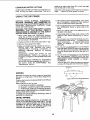
7. Lay a piece of flat straight wood and a square on
saw table and rotatethe SPREADER SUPPORT
until the bracket is aligned with square.
B.
24
sPACE
EQUAL
3 THICKNESSES
.-
WARNING:
AVORD
iNJURY
ACCIDENTAL
START, TURN SWITCH OFF AND
REMOVE PLUG FROM POWER OUTLET.
iMPORTANT:
The SPREADER must always be y=am
the
cut (KERF)
made
by the and
sawblade,
PARALLEL
to the
sawb,ade
in the MIDDLE of
NOTE:
The
spreader
is
thinner
than
the width
of the
KERF by approximately six thicknesses
of paper.
TO APPROX,
OF PAPER
KERF
_
J
WOOD
_:_._ ,_
BLADE
.f._-.
_..... _.-:L ....
,
"_" _ -- ......................
\._[_'C:3;:.:Ci
C_ -- _
_--
sPR
_._
_/
SPACE
:___:i!__i__
- ----__
"'z2 _._
........ _
l_]i!i
EQUAL
-
TO
APPROX.
LOOKING
DOWN
ON
SAW
3 THIC KN ESSES OF PAPER
1. Make two folds in a small piece (6 x 6 in,) of
ordinary
NEWSPAPER
making
three
thicknesses. The folded paper will be used as a
"spacing gauge".
/
2, Install TRUSS HEAD SCREWS, SPREADER
CLAM P and WING NUTS to spreader bracket. Do
net tighten wing nuts. Place spreader between
spreader clamp and bracket. Move forward until
all three are in line. TIGHTEN WING NUTS.
;1ANT,K,CKBACK
t
/
J
t,
t
_ |/[!
PAWLS
I_ _/
t TIGHTLYAGAINSTI
t ft ,J/
1 .OLD*OOD
3. Lift up both ANTIKICKBACK
PAWLS ... insert
one of the setscrew wrenches or a pencil in the
notches to hold the pawls out of the way.
4. Lay a piece of straight flat wood against the
sawblade. Insert folded paper between spreader
and strip of wood.
5, MAKE SURE THE HEX NUTS UNDERNEATH
ARE LOOSE,
6. Hold the spreader tightly against the wood and
make sure the wood is against the saw blade.
TIGHTEN THE HEX NUTS.
This will align the spreader in the middle of the
cut (KERF) made by sawblade.
7. Lower the antikickback
pawls The end of the
right hand (viewed from front of saw) pawl should
move down and clear the end of the small slot
provided in the insert. If end of the right hang
ADJUSTING
MITER
_.
_
_
HOLD
_
WING NUT
F
I
/
_
TIGHTLY
SPREADER
AGAINST
WOOD
SPREADER
BRACKET
SPREADER
CLAMP
pawt strikes the metal of the insert, reposition tl
sp reader support.
GAUGE
NOTE: The slots for the stop pin and the
graduations are manufactured
to very close
tolerances which provide accuracy
for average
woodworking.
In some cases where extreme
accuracy is required, when making angle cuts, for
example, make a trial cut and then recheck it.
1, Loosen the "knob , and pull 'stop pin" OUT.
INDICATO
BLOCK
necessary,
4. If the head is not square with the bar, adjustments
are required.
A. Loosen the "knob" (1) and the "two screws"
(2).
B. Position the HEAD square with the BAR using
a combination square.
C. PUSH the STOP PIN into the slot in the head at
"0"...
push the pin into the slot and twist it.
Lock the knob.
D. Recheck with the soluare. If the head is still not
square, loosen the screws (2) and readjust t.he
iNDiCATOR BLOCK.
E. With the head square with the barand the pun
pushed into the slot adjust the pointer (3) to
point to "0".
F. The miter gauge head must rest on top of the
bar without being able to move up and down
•. , yet.it must swivel freely.
G. The swiveling movement of the head can be
adjusted
by tightening
or loosening
the
setscrew (4) . . . using the 1/8 in. setscrew
wrench.
NOTE: The setscrew is located inside of the
head. To reach it, swivel the head to 60
degrees and turn the miter gauge upside
down.
ASSEMBLING
1/8 IN. SETSCREW
WRENCH
HOLD-DOWN
Locate the clamp assembly, support rod, two wing
screws and two washers in loose parts bag.
Screw the support rod (1) tightly into the hole in the
miter gauge head.
Position the clam p assembly (2) on the handle and
rod .. install washers (3) an(_ wing screws (4).
NOTE: The sma!l knob (5) on the clamp screw must
not turn. Check nut underneath it ... it must betight
against the knob. Use a 1/2 inch wrench to tighten it.
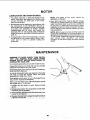
PLUGGING
IN
I
MOTOR
1. From among the loose parts, find two wire tieS.
2. Route motor cord along right side of cabinet and
snap ties in 1/4" hole in stde of cabinet. Secure
two cords in wire ties.
3. Plug motor cord into outlet on side of switch box.
WIRE TIES
PICTURE
26
CLARITY
GETTING
TO KNOW YOUR SAW
9 SAWBLADE
8
MITER
LOCK
GAUGE
HANDLE
10
TABLE
INSERT
EXACT-I-CUT
ANTIKICKBACK
PAWLS
RIP
FENCE
HOLES
ATTACHING
6
MITER
GAUGE
, ,UNO..EAT,,ABLE,
TI TLOOK.A"O
2
ELEVATION
\
HANDWHEEL
3
1
1
ON-OFF
ON-OFF
TILT HANDWHEEL
SWITCH
SWITCH
CAUTION: Before turning switch on, make sure the
blade guard is correctly installed and operating
properly.
The On-Off Switch has a locking feature. THIS
FEATURE
IS INTENDED
TO PREVENT
UNAUTHORIZED
AND POSSIBLE HAZARDOUS
USE BY CHILDREN AND OTHERS.
A. TO turn saw ON... stand to either side of the
blade never in line with it . . . insert finger
under switch lever and pull END of lever out.
Do not cycle the motor switch on and off
rapidly, as this may cause the sawblade to
loosen. In the event this should ever occur.
allow the sawblade to come to a cornplete
stop and retighten the arbor nut normally, not
excessively. Never leave the saw while the
power is "ON".
B. TO turn saw OFF.
. PUSH lever in. Never
leave the saw until the cutting tool has come
to a complete stop,
C. TO lock switch in OFF position.., hold switch
IN with one hand... REMOVE key with other
hand,
KEY
(YELLOW PLASTIC)
WARNING:
FOR YOUR OWN SAFETY,
LOWER BLADE OR OTHER CUTTING
TOOL BELOW TABLE SU RFACE. (IF BLADE
IS TILTED, RETURN IT TO VERTICAL (90 ° )
POSITION). ALWAYS LOCK THE SWITCH
OFF. WHEN SAW IS NOT IN USE..
•
REMOVE KEY AND KEEP IT IN A SAFE
PLACE . . . ALSO . .. IN THE EVENT OF A
POWER FAILURE (ALL OF YOUR LIGHTS
GO OUT) TURN SWITCH OFF ... LOCK IT
AND REMOVE
THE KEY. THIS WILL
PREVENT THE SAW FROM STARTING UP
AGAIN WHEN THE POWER COMES BACK
ON.
27
FOR
FACING
2
3
4
ELEVATIONHANDWHEEL...
elevates or
lowers the blade, Turn clockwise to elevate..
counterclockwise to lower.
NOTE: Any time sawblade has been elevated
to 2-5/8 inches or higher above the table it will
be necessary to lower the blade by turning the
elevation handwheel 5 turnscounterclockwise
before tilting to bevel.
TiLT HANDWHEEL...
tilts the blade for bevel
cutting. Turn clockwise to tilt toward left
counterclockwise to tilt toward vertical.
When the blade is tilted to the LEFT as far as it
will go, it should be at 45 ° to the table and the
bevel indicator should point 45 °,
NOTE: There are LIMIT STOPS on the saw
which prevent the blade from tilting beyond
45 ° to the LEFT and 90° to the RIGHT. (See
"Adjustments"
section
"Blade
Tilt, or
Squareness of Blade to Table").
8
MITER GAUGE..
head is locked in position
for crosscutting or mitering by tightening the
lock knob. ALWAYS LOCK IT SECURELY
WHEN IN USE.
There are slots for the stcp pin at the 45 deg tee
right and left positions for conveniently setting
the Miter Gauge to cut miters,
NOTE: The slots for the stop pin and the
graduations are manufactured to very close
tolerances which provide accuracy for average
woodworking.
In some cases where extreme
accuracy is required, when making angle cuts,
for example, make a trial cut and then recheck
it.
If necessary, the miter gauge head can then be
swiveled slightly to compensate and then
locked.
Slots are provided in the miter gauge for
attaching an AUXILIARY FACING to make it
easier to cut long pieces. Be positive facing
does not interfere with the proper operation of
the sawblade guard.
Select a suitable piece of smooth straight
wood . . ari]l two holes and attach it with
screws.
NOTE: When bevel crosscutting, attach facing
so that it extends to the right of the miter gauge
and use the miter gauge in the groove to the
right of the blade.
TILT LOCK HANDLE...
locks the blade in the
desired
tilt position.
To loosen
turn
counterclockwise. Push handle in and turn itto
another position if necessary in order to
tighten or loosen.
!MPORTA.NT: Be sure handle Is hanging in the
DOWN
position before tilting blade. If it Is
pointing to the 1 o'clock position it may jam on
underside of the table and bend the locking
bolt,
5
RIP FENCE... is locked in place by tightening
the lock knob. To move the fence, loosen the
knob and grasp the fencewith one hand at the
fro nt.
Holes are provided in the rip fence for
attaching a wood facing when using the dado
head, or molding head.
Select a piece of smooth straight wood approx.
3/4" thick, at least as long as the rip fence, and
at least 7-1/2" wide (high)to permitclamping
of featherboards.
Attach it to the fence with three Round Head
#10 Wood Screws 2 in. long. To remove the
facing, loosen the screws, slide the facing
forward and pull the screws through the round
holes.
If you are making a rip type cut in material
thinner than 3/16 in. while the fence is
positioned over the depressed area of table
extension, the facing should be attached to the
fence so thatthe bottom edge touches the top
surface of the extension. In this case, the
facing must be shorter than the fence. This will
prevent thin material from sliding under the rip
fence.
WOOD
)LD DOWN
CLAMP
LOCK
ARY
STOP
FACING
PIN
FACING
45 ° SLOT
FOR STOP
PIN
7
BLADEGUARD must always be in place and
work ng properly for all thru-sawing cuts. That
is, all cuts whereby the blade cuts compete y
through the workpiece.
To remove the guard for special operations,
loosen the wing nuts and slide the guard off of
the rod. DO NOT DISTURB THE SETTING OF
THE ROD.
When rep acing the guard, make sure the PIN
in the rod engages with the NOTCH n the
spreader support. Make sure wing screws are
tightened securely.
8
TABLE INSERT is removable for removing or
installing blades or other cutting tools.
_G: TO
AVOID
INJURY
DUE TO
;H "OFF"
POWER
VING
surface.
d pull toward
ROUND HEAD
/
#10 WOOD SCREWS
28
BLADE
NEVER OPERATETHE SAW WITHOUTTHE
PROPERINSERTIN PLACE. USE THE SAW
BLADEINSERTWHENSAWING, . . USE THE
COMBINATION
DADO
22271) WHEN DADOING
MOLDING
INSERT
OR MOLDING.
GUARD
NOT
SHOWN
FOR PICTURE
CLARITY
.......
(9BLOCK
<._>
il/
:)R NUT
LOOSE
COLLAR
ARBOR
SCREW
_@_
TEETH
POINTING
FRONT
9
REMOVING AND INSTALLING SAWBLADE.
WARNING:
TO AVOID INJURY DUE TO
ACCIDENTAL START, TURN SWITCH "OFF"
AND
REMOVE
PLUG
FROM
POWER
SOURCE OUTLET BEFORE REMOVING OR
iNSTALLiNG SAWBLADE.
10
ARBOR
NUT
TO .--,.-_
OF SAW
t%...
EXACT-I-CUT
The "yellow" plastic disc imbedded in the table
in front of the sawblade, is provided fol
marking the location of the "sawcut" on the
workpiece.
A. Check disc ... if it is above table surface
place a piece of hardwood on top of it and ta!:
it down.
A. Raise Blade Guard ... remove insert.
B. To REMOVE blade, place a block of wood
against front of blade. _. PULL arbor wrench
toward you to LOOSEN arbor nut.
B. With blade 90 ° (square to table) cut off -"
piece of wood.
C. Pull miter gauge back until wood isover disc
Using very sharp pencil, mark a line on disc
D. With miter gauge in right hand g roove, follow
same procedure and mark another line or
disc.
E. These lines indicate the "path" of the cu'
(kerf) made by the sawblade.
F. When cutting the workpiece, line up mark or
workpiece With line on disc.
//,_
///_\ _'-
.....
_P,_I_#(_H
///////_L_
i!fF y
'BOR
WOOD
SLOCK
BLADE
GUARD
NOT
SHOWN
FOR
NU."
PICTURE
i_J
j//
CLARITY
C. TO TIGHTEN arbor nut, place a block of
wood against rear of blade... PUSH wrench
away from you.
When installin_l the blade . . . make sure the
teeth are pointing
. andthatthebladeandcollarsareclean
and
free from any burrs.
The HOLLOW side of the collar must be
against the blade.
Always tighten the arbor nut securely.
NOTE: When using the Dado or Molding Head,
it s not necessary to install the loose collar.
usethehold- own
c .mp(optional
accessor
\\\'
on the miter gauge for greater accuracy.
@
_P_I_J__I_
_____....--_j_r
_-'-_--_I _I_JJdl_
_-_\iJ_
_
__.J_-_----_
_
_
_'_
toward
,he
,root
ofthe
saw
To replace insert.
Place insert into insert opening in table and
push toward rear of saw to engage spring clip
and until keyslot in insert will drop over screw.
__
_
"_
y
BLADE
GUARD
_
NOT
_"
,
Z
,_/..-___-'P('_-'_"-"__L__.__ -___
_
SHOWN
FOR
PICTURE
F
,¢
Do not tighten screw to the point where it will
deflect the insert.
_._._.,___
CLARITY
_
BASIC SAW OPERATION
WORK
THESE EDGES MUST
BE PARALLEL
HELPERS
Before cutting" any wood. on,,your saw, study all of
the "Basic Saw Operations.
Notice that in order to make some of the cuts, it is
necessary to use certain devices "Work Helpers"
like the Push Stick, the Push Block and the Auxiliary
Fence/Work Support, which you can make yourself.
After you have made a few practice cuts, make up
these "helpers" before starting any projects. Make
the "Push Stick" first.
3/4 PLYWOOD
\
\
PUSH BLOCK
3/8
2-1/2
3/8
SLIGHTLY LESS THAN
THICKNESS OF WORKPIECE
UP TO 3/a'"
1-5/8
1
NOTE:
AUXILIARY
All dimensions
FENCE/WORK
I
318 PLYWOOD
in inches
SUPPORT
Make one using a piece of 3/8 in. and 3/4 in.
plywood.
Fasten
together
with glue and
woodscrews.
NOTE: Since the Push Block is used with the
Auxiliary Fence, the 4-3/4 in. dimensions must _)e
held identical on both the pieces.
45 ° NOTCH
AUXILIARY FENCE/
WORK SUPPORT
NOTE:
All dimensions
in inches
27
PUSH STICK AND PUSH BLOCK
Make the Push Stick using a piece Of 1 x2,or ripone
from a wide board, say 11-1/2 in. wide, and set the
rip fence 9-7/8 in. from the sawblade.
Make the Push Block using a piece of 3/8 in. and 3/4
in. plywood.
The small piece of wood 3/8 in. x 3/8 in. x 2-1/2 in.
should be GLUED to the plywood ... DO'NOT USE
NAILS. This isto prevent dulling the sawblade in the
event you mistakingly cut into the push block.
Position the handle in the centerof the plywood and
fasten together with glue and woodsorews.
USING
THE MITER
314 PLYWOOD
1-1/4
THIS FACE AND THIS
EDGE MUST BE PARALLEL
'
N
3/8 PLYWOOD
"\
NOTE:
All dimension
in inches
5-1/2
_%_/"
GAUGE
6. Do not stand directly in front of the blade in case
of a THROWBACK (Small cut-off piece caught
by the back of the blade and thrown toward the
operator). Stand to either side of the blade.
7. Keep your hands clear of the blade and out of
the path of the blade.
8. If blade stalls or stops while cutting, TURN
SWITCH OFF before attempting
to free the
blade.
9 Do not reach over or behind the blade to pull the
workpiece through the cut.., to support long or
hea_ workpieces •. •to remove cut-off pieces of
mate='ial or FOR ANY OTHER REASON.
THE
MITER
GAUGE
IS USED
WHEN
CROSSCUTTING,
MITER
CUTTING,
BEVEL
CUTTING,
COMPOUND
MITER
CUTTING,
DADOING
and when RABBETTING
AND
MOLDING across the end of a narrow workpiece.
WARNING: FOR YOUR OWN SAFETY, ALWAYS
OBSERVE
THE
FOLLOWING
SAFETY
PRECAUTIONS IN ADDITION TO THE SAFETY
INSTRUCTIONS
ON PAGES 2, 3, and 4.
1. Never make these cuts freehand (without using
the miter gauge or other auxiliary devices)
because the blade could bind in the cut and
cause a KICKBACK or cause your fingers or
hand to slip into the blade.
Use.
3. Remove
rip fence
from table.
th_
gut
EN
KI(
remove small pieces of cut-off material
Ly become TRAPPED inside the blade
ihile the saw is RUNNING. THIS COULD
_GER YOUR
HANDS
or cause a
_CK.
Turn
e saw OFF. After the blade has stopped
turning, lift the guard and remove the piece.
would increase the hazard potential.
3O
WORKPIECE
!
CROSSCUTTING
CROSSCUTTING
is known as cutting wood across
the grain, at 90 ° , or square with both the edge and
the flat side of the wood. This is done with miter
gauge set at "0".
The graduations on the miter gauge provide
accuracy for average woodworking. In some cases
where extreme at:curacy is required, when making
angle cuts, for example, make a trial cut and then
recheck it with an accurate square, or protractor.
r I
JtI
l
TABLE
If necessary, the miter gauge head can be swiveled
slightly to compensate for any inaccuracy.
NOTE: The space between the miter.gauge barand
the groove in the table is held to a minimum during
manufacturing.
For maximum accuracy when using the miter
gauge, always "favor" one side of the groove in the
table, in other words, don't move the miter gauge
from side to side while cutting, but keep one side of
the bar riding against one side of the groove.
NOTE: Glue a piece of sandpaper to the face of the
miter gauge head. This will help prevent the
workpiece from "creeping" while it is being cut.
The Hold-Down Clamp included with 113.241690
should be used on the miter gauge for greater
accuracy.
The miter gauge may be used in either of the
grooves in the table. Make sure it is locked.
When using the miter gauge in the LEFT hand
groove, hold the workpiece firmly against the miter
gauge head with your left hand, and grip the lock
handle with your right.
When using the RIGHT Hand groove, hold the
workpiece with your right hand and the Iockhandle
with your left hand.
\
When cutting long workpieces, invert AUXILIARY
FENCE/WORK SUPPORT and position it on top of
the guide bars to support the work pieces as near to
the end as possible. If this does not adequately
support the workpiece, you can make a simple
support by clamping a piece of plywood to a
sawhorse,
Use the Hold-Down
Clamp
included
with
113.241690 on miter gauge for greater accuracy.
AUXILIARY
FENCE/
WORK SUPPORT
\
REPETiTiVE
CUTTING
REPETITIVE CUTTING
is known as cutting a
quantity of pieces the same length without having to
mark each piece.
1. Use the Stop Rods (optional accessory) only for
cutt ng dup icate pieces 6 in. long and longer.
2, Follow all Safety Precautions and Operational_
Instructions for Cross Cutting.
When making repetitive cuts from a long workpiece.
Use
I
WORK
SUPPORT
\
1. NEVER USE THE RIP FENCE'AS
A LENGTH
STOP BECAUSE THE CUTOFF PIECE COULD
BIND BETWEEN THE FENCE AND THE BLADE
CAUSING A KICKBACK.
\
\
\
BLOCK
2. When making repetitive cuts shorter than 6 in..
clam p a block of wood 2 in. long to the table to act
as a length stop. Do not clamp directly to the
bottom edge of the table because the 'swivel of
the clamp will not grip properly, Place a small
block of wood between the bottom edge of the
table and the "(3" clamp.
CAUTION: When clamping the block, make sure
that the end of the block is well in front of the
sawblade. Be sure it is clamped securely.
3. Slide the workpiecealong
the miter gauge until it
touches the block..,
hold it securely or clam _>it
with the Hold-Down
Clamp
included
with
113.241690.
4 Make the cut.., pull the workpiece back ... push
the cut off piece off the table with a long push
MITER
stick. . . DO NOT ATTEMPT TO PICK IT UP AS
THIS COULD ENDANGER YOUR HANDS.
CUTTING
MITER CUTTING is known as
angle other than 90 ° with the
Follow the same procedure
crosscutting.
Adjust the miter gauge to the
lock it.
TABLE
cutting wood at an
edge of the wood.
as you would for
desired angle, and
The miter gauge may be used in either of the
grooves in the table.
When using the miter gauge in the LEFT Hand
groove, hold the workpiece firmly against the miter
kgauge head with your left hand, and grip the lock
nob with your right.
When using the RIGHT hand groove, hold the
workpiece with your right hand and the knob with
your left hand.
Use the Hold-Down
Clamp included
with
113.241690 o n the miter gauge for greater accu racy.
BEVEL
CROSSCUTTING
BEVEL
CROSSCUTTING
is the same as
crosscutting except that the wood is also cut at an
angle . . . other than 90° with the flat side of the
wood
NOTE: Anytime saw blade has been elevated to 25/8 inches or higher above the table, it will be
necessary to lower the blade by turning the
elevation handwheel 5 turns counterclockwise
before tilting to beVel
'\
Adjust the blade to the desired angle.
the
LEFT because the blade
Use the AUXILIARY
FENCE/WORK
\
and the
SUPPORT for
workpiece as near to the end as possible.
Use the Hold-Down
Clamp included
with
113.241690 on the miter gauge for greater accuracy.
32
COMPOUND
made at an angle other than 90 ° to both the edg_
and the flat side of the wood,
MOTER CUTTING
COMPOUND MITER CUTTING is a combination of
miter cutting and bevel crosscutting.
The cut is
Adjust the miter gauge and the blade to the desirec
angle.,.
Make sure miter gauge is locked.
USING THE RmPFENCE
5. Have blade extend approximately 1/8 in. abow
top of workpiece. Additional blade exposun
would increase the hazard potential.
RIPPING,
BEVEL
RIPPING,
PLOUGHING,
MOLDING,
RESAWING
AND RABBETING are
performed using the RIP FENCE together with the
AUXILIARY
FENCE/WORK
SUPPORT,
PUSH
STICK OR PUSH BLOCK.
6. Do not stand directly in front of the blade in casq
of a KICKBACK. Stand to either side of th,
blade.
WARNING: FOR YOUR OWN SAFETY, ALWAYS
OBSERVE
THE
FOLLOWING
SAFETY
PRECAUTIONS iN ADDITION TO THE SAFETY
iNSTRUCTIONS
ON PAGES 2, 3, and 4.
7. Keep your hands clear of the blade and out c
the path of the blade.
8. If the blade stalls or stops while cutting. TURf
SWITCH OFF before attempting
to free th_
blade.
1. Never make these cuts FREEHAND (without
using the rip fence or auxiliary devices when
required) because the blade could bind in the
cut and cause a KICKBACK.
9. Do not reach over or behind the bladeto pull th,
workpiece through the cut.., to support long o
heavy workpieces..,
to remove small cut-c1
pieces of material or FOR ANY OTHEI
REASON.
2. Always lock the rip fence securely when in use.
3. Remove miter gauge from table.
4. Make sure blade guard is installed for all thrusawing
type
cuts.
Replace
the guard
IMMEDIATELY
following
completion
of
resawing,
rabbeting,
dadoing,
or molding
operations.
Frequently
check
the action
of the
ANTIKICKBACK
PAWLS by passing
the
workpiece alongside of the spreader while saw
is OFF.
Pull the workpiece TOWARD you. If the PAWLS
do not DIG into the workpiece and HOLD it _ ..
the pawls
must be SHARPENED.
See
"Maintenance"
section.
!0. Do not pick up small pieces of cut-off materi_
from the table. REMOVE them by pushing ther
OFF the table with a long stick. Otherwise the
could be thrown back at you by the rear of th
blade.
11. Do not remove small pieces of cut-off materi_
that may become TRAPPED inside the blad
guard while the saw is RUNNING. THIS COULI
ENDANGER
YOUR HANDS
or cause
KICKBACK.
Turn the saw OFF. After the blade has stoppe
turning, lift the guard and remove the piece.
WORKPIECE
IF-.
RiPPiNG
L " )
RIPPING is known as cutting a piece of wood with
the grain, or lengthwise. This is done using the rip
fence.
Position the fence to the desired Wl DTH OF RIP and
lock in place.
Before starting to rip, be sure
A. Rip Fence is parallel to sawblade.
B. Spreader is properly aligned with sawblade.
C. Antikickback pawls are functioning properly.
When ri pping LONG BOARDS or LARGE PANELS.
always use a we rk support ....
A simple one can be made by clamping a piece of
plywood to a sawhorse.
TABLE
ALWAYS
BEVEL RIPPING
fWhen bevel ripping material 6 in. or narrower, use
ence on the right side of the blade ONLY. This will
mounted to the left, the sawblade guard may
interfere with proper use of a push stick.
33
SUPPORT
LONG
WORKPIECES
When "Wl DTH OF RIP" is 6 in. and Wi DER use your
RIGHT Hand to feed the workpiece until it is clear of
the table.
Use LEFT hand ONLY to guide the .work piece
not FEED the workp ece with the left hand,
When "WIDTH OF RIP" is 2 in, to 6 in. wide
PUSH STICK tc feed the work.
... do
USE THE
When WIDTH OF RIP is NARROWER
than 2 in,. the
push stick CANNOT be used because the guard will
interfere...
USE the AUXILIARY FENCE/WORK
SUPPORT and PUSH BLOCK.
Attach Auxi!!ary Fence/Work
with two ' C c amps.
Support
to rip fence
/
34
Feed the workpie'ce by hand along the AUXILIARY
FENCE until the end is approx. 1 in. past the front
edge of the table. Continue to feed using the PUSH
BLOCK.
Hold the workpiece in position and install the PUSH
BLOCK by sliding it on top of the AUXILIARY
FENCE/WORK SUPPORT (This May Raise Guard)-
BAFFLE
Narrow strips thicker than the Auxiliary Fence/Work
Support may enter the guard and strike the baffle.
CAREFULLY raise guard only enough to clear the
workpiece. Use PUSH BLOCK to complete cut.
PLOUGHING
AND MOLDING
MOLDING is shaping the workpiece with the grair
the long way of the workpiece, using the fence. USE
Featherboards and push sticks as required.
PLOUGHING
is grooving with the grain the long
way of the workpiece,
using the fence.
USE
Featherboards and push sticks as required.
I
PLOUGHIN
MOLDING
35
RESAWING
RESAWING is known as ripping a piece of wood
through its thickness. Do not attempt to resaw
BOWED or WARPED material. NOTE: To RESAWa
piece of wood wider than 3-3/8 in...
it will be
necessary to remove the blade guard ... and use the
AUXILIARY FENCE/WORK SUPPORT. (See "Work
Helpers").
SMALL
BLOCK
OF WOOD
Clamp it to the table so that the workpiece will
SLIDE EASILY but not TILT or MOVE SIDEWAYS
without BINDING between the two fences.
/
Do not clamp directly tc the bottom edge of the table
because the "swivel" of the clamp will not grip
properly. Place a small block of wood between the
bottom edge of the table and the "C" clamp.
WARNING: FOR YOUR OWN SAFETY...
2. MAKE FIRST PASS TO A DEPTH SLIGHTLY
LESS THAN ONE-HALF THE WIDTH OF THE
BOARD;
KEEP SAME FACE OF BOARD
AGAINST FENCE FOR SECOND PASS AS THE
FIRST PASS.
I. DO NOT "BACK UP" (REVERSE FEEDING)
WHILE RESAWING BECAUSE THIS COULD
CAUSE A KICKBACK.
3. iNSTALL BLADE GUARD IMMEDIATELY UPON
COMPLETION
OF THE
RESAWING
OPERATION.
AUXILIARY
FENCE/
WORK SUPPORT
CUTTING
PANELS
When cutting panels (whenever fence is positioned
outside of table surface), ALWAYS
use the
AUXILIARY FENCE/WORK SUPPORT.
1. Unlock fence and raise rear end.
2. Position AUXILIARY FENCE/WORK SUPPORT
as shown and attach it with two "C" clamps.
RABBETING
RABBETING is known as cutting out a section of the
corner of a piece of material, across an end oralong
an edge.
To make a RABBET requires cuts which do not go
all the way through the material. Therefore the blade
AABDET
S 00"D
F
1. Remove blade guard.
2. For rabbeting along an edge (long way of
workpiece) as shown, add facing to rip fence
approximately as high as the workpiece is wide.
Adjust rip fence and blade to required
dimensions; then make first cut with board flat on
table as any rip (type) cut; makesecond cut with
workpiece On edge. Follow all precautions, safety
instructions, and operational instructions as for
/
j
/
//
RABBETING
ACROSS THE END
RABBETING
ALONG
TNE EDGE
piece to obtain thedesired width of cut. DO NOT
3. For rabbeting across an end, for workpiece 101/2 and narrower make the rabbet cut w th the
board flat on the table. Using the miter gauge
fitted with a facing follow the same procedures
and instructions
for cross cutting, making
successive cuts across the width of the work-
use the rip fence for rabbeting across the end,
4. INSTALL BLADE GUARD IMMEDIATELY UPON
COMPLETION OFRABBETING OPERATION.
Rabbet cuts can be made in one pass of the workpieceoverthe cutterusing thedado head or molding
head.
DADOING
Instructions for operating the Dado Head are
contained in boo _let furnished with the Dado Head.
The Recommended
Dado Head is listed under
Recommended Accessories in this manual.
The arbor on the saw, is only long enough so that
the widest cut that can be made is 13/16" wide.
o
It is not necessary to install the outside loose collar
before screwing on the arbor nut. Make sure the
arbor nut is tig ht.
ALWAYS USE DADO INSERT LISTED UNDER
RECOMMENDED ACCESSORIES.
When using the dado head it will be necessary to
remove the Blade Guard and Spreader. Use Miter
Gage and follow same procedures ano Instructions
for C ross Cutting.
ALWAYS REPLACE THE BLADE, GUARD AND
SPREADER
WHEN
YOU ARE
FINISHED
DADOING.
MOLDING
Always
use Molding
Insert
Recommended Accessories.
Listed
Under
When using the molding head it will be necessaryto
remove the Blade Guard and Spreader. USE
ARBOR
_
SAW ARBOR
REMOVE SAWBLADE
.J
INSTALL
DADO
AND
HEAD
BACK OF SAW
CAUTION. USE FEATHERBOARDS
AND PUSH
STICKS, etc AS REQUIRED.
ALWAYS REPLACE THE BLADE GUARD AND
SPREADER
WHEN
YOU
ARE
FINISHED
MOLDING.
FEATHERBOARDS
Before starting the operation (switch
cutter below table surface):
Add 8 inch high flat facing board to the fence, the
full length of the fence.
Use featherboar.ds
for all non "thru-sawing"
operations
(when
sawblade guard must be
removed). Featherboards are used to keep the work
in contact with the fence and table as shown, and to
stop kickbacks.
Mount featherboards to fence and table as shown,
so that leading edges of featherboards will support
workpiece until cut is complete, and the workpiece
has been pushed completely
past the cutter
(sawblade, dado head molding head, etc.) with a
pushstick, as in ripping.
"OFF"
and
(a) Install featherboards so they exert pressure on
the work piece; be positive they are secure, and
(b) Make sure by trial that the featherboards will
stop a kickback if one should occur.
Featherboards are not employed during non thrusawing operations when using the miter gauge.
Replace the sawblade guard as soon as the non
thru-sawing ooeration is complete.
/
"C" CLAMPS
FEATHERBOARD
WORK
:OLLA_
CUTTING
Instructions
for operating the Molding Head are
contained in a booklet furnished with the Molding
Head.
The recommended
molding head is listed under
Recommended Accessories in this manual
USING
LOOSE
o
SUPPORT
37
MOTOR
LUBRICATmON
AND MAINTENANCE
1. The sleeve bearings, in both end shields of the
motor, have been lubricated at the factory with
correct lubricant. No other part of the motor
requires lubrication,
2. Re-lubricate motor bearings in accordance with
the instructions
on the nameplate. Be sure to
wipe off dirt or grit if present around oil hole caps
to prevent any possibility of foreign material
contaminating
the oil wicks that supply the
bearings with oil. Use a good grade of medium
weight mineral oil, such asautomobileengine
oil,
SAE 2(3.
4.
3. If disassembly of the motor is necessary, it should
be returned to your nearest Sears retail or mailorder store jn order to prevent voiding the
g ua rantee.
NOTE: The speed of this motor canno_ be
regulated or changed.
Every effort should be made to prevent foreign
material from entering the motor. When operated
under conditions likely to permit accumulations
of dust. dirt, or waste within the motor, a visual
inspection should be made at frequent intervals.
Accumulations of dry dust can usually be blown
out successfully.
NOTE: Motors used on wood-working
tools are
;)articularly susceptible to the accumulation
of
sawdust and wood chips and should be blown out
or "vacuumed" frequently to prevent interference
with
normal motor
ventilation
and proper
operation of the centrifugally-operated
starting
switch.
MAINTENANCE
WARNING: TO AVOID INJURY, TURN SWDTCH
"OFF" AND
REMOVE PLUG FROM POWER
SOURCE OUTLET BEFORE MAINTAINING
OR
LUBRICATING YOUR SAW.
Do not allow sawdust to accumulate inside the saw.
\
Frequently blow out any dust that may accumulate
inside the saw cabinet and the motor.
FrequenUy clean your cutting tools with Craftsman
Gum and Pitch Remover.
A coat of automobile-type
wax applied to the table
will help to keep the surface clean and allow
workpieces to slide more freely.
If the power cord is worn or cut, or damaged in any
way, have it replaced immediately.
Make sure the teeth of the ANTIKICKBACK pawls
are always sharp. To sharpen:
1. Identify the dull tooth or teeth. Remove blade
guard.
2. Rotate pawl toward rear of spreader so that teeth
are above top of spreader.
.i j
¸¸¸¸38
LUBRiCATiON
eventually age and harden so that it witl not prov | €
an adequate oil film between
the core and cas_r
liner and must be replaced.
The following parts should be oiled occasionally
with SAE No. 20 or No. 30 engine oil.
1. Tilt screw threads and pivot nut. (First Clean with
Craftsman Gum & Pitch Remover.)
2. Elevation screw threads and pivot nut. (First
Clean with Craftsman Gum & Pitch Remover.)
LUBRICATmON
1 Remove the core from the casing, clean the co
by washing
with kerosene
or an approve
solvent.
3. Cradle bearing points.
4. Bearing points in guard assembly,
and rip fence.
LUBRICATION
PROCEDURES
2. Dry the core.
miter gauge
3. Inspect the core for worn or broken
is damaged,
it should be replaced.
OF FLEXIBLE SHAFT
wires,
if co
4. "Butter" the entire length of the core with a goc
grade of general purpose bearing
grease witf _
minimum
operating
temperature
of-40°F
a_
reassemble
in casing. DO NOT force 'the grea
into the casing
with a grease gun. Too mLJ,
grease wil affect shaft life because it makes t
core work ha rder.
Flexible shafts do require ;)eriodic lubrication
because the core acts as a screw conveyor which
will ;>umpthe lubrication to one end of the shaft over
an extended period of operation. The frequency of
lubrication depenes on how the saw is used. When
the saw operates continuously for long periods of
time a lubrication schedule should be developed.
The time period may be every 80 or 100 hours. An
indication that the shaft needs lubrication is when it
becomes noisy. Conversely, when the saw has
limited and infreauent
use, the grease will
GUAR__
BEARING
]1_ BEARING POINTS
RECOMMENDED
POINTS
ACCESSORIES
ITEM
CAT. NO.
Steel Stand ...........................
9-22214
Caster Sets .................
9-22222 or 9-22221
Solid Table Extension .................
9-29957
7 In. Molding Head Set ..................
9-3217
7 In. Molding Head Set ..................
9-3218
7 In. Molding Head ......................
9-32t4
Molding/Dado Insert for 7 in.
Dia. Molding or Dado Head ..........
9-22271
Work Light .............................
9-2480
Sawdust Collection System ............
9-24242
in'
" Sawblades with 5/8" Bore
See Catalog
,v Dia.
Work Light .............................
9-2481
ITEM
CAT. IN
7 In. Dia. Adjustable Dado Head
9-3261 - 9-3262 - 9-3,_
7 In, Dia. Dado Head .....................
9-31_
Sending Wheel .......................
9-22-_
Miter-Gauge StOp Rods ...............
9-29S
Miter-Gauge Hold-Down Clamp .......
9-29_
Taper Jig ...............................
9-3:
Universal Jig ...........................
9-3:
Powe Tool Know How Handbook
Table Saw ............................
9-_€
2 "
Cast Iron Extension, 12 x 27 Inches ....
9- _=
Rip Fence Bar
...................
Table Extension Kit ...................
39
9"2°J_"
9-2_"
TROUBLE
SHOOTmNG
WARNING: TO AVOID INJURY, TURN SWITCH "OFF" AND ALWAYS REMOVE PLUG FROM POWER SOURCE
OUTLET BEFORE TROUBLESHOOTING.
TROUBLE
TROUBLE
SHOOTING
-- GENERAL
r PROBABLE CAUSE
Excessive vibraUon.
REMEDY
1. Blade out of balance.
,
|
1. Discard Blade and use a different
,.
1. Miter gauge not adjusted
Cut when crosscutting•
1. See "Adjusting
blade.
Miter Gauge."
properly.
Cut binds, burns or
stalls motor when
1. Dull blade with improper
tooth set.
"
1. Sharpen or replace blade.
2. Blade is Heeling.
2. See "Heeling
3. Warped board.
3. Make sure concave or hollow side is facing
"down," feed slowly.
4. Rip fence not parallel
to blade.
4. See "Aligning
Rip Fence"
5. Spreader out of
5. See "Aligning
Spreader."
Adjustment..."
alignment.
Cut not true at 90°
.1. Stop screws not properly
or 45 ° positions.
I
Tilt and elevating
1. See "Blade Tilt", or "Squareness
adjusted,
to Table."
1. Sawdust on threads of tilt
handwheel turn hard.
1. See "Maintenance
screw or elevating screw,
I
i
of Blade
2. Bearing retainers
too tight.
TROUBLE
and Lubrication"
section.
2, See "Tilt Mechanism."
SHOOTING
-- MOTOR
NOTE: Motors used on wood-working tools are particularly susceptible to the
accumulation
of sawdust and wood chips and should be blown out or "vacuumed"
frequently to prevent interference with normal motor ventilation.
TROUBLE
PROBABLE
' Excessive noise.
CAUSE
REMEDY
1. Motor.
1. Have motor checked by qualified
I
•
.......
Motor falls to develop
LOW VOLTAGE:
I
service
technician. Repair service is available at
your nearest Sears store.
|
i 1. Circuit overloaded with
lights, appliances and
other motors.
1. Do not use other appliances or motors o,
same circuit when using the saw.
length of
output.)
4O
TROUBLE
SHOOTING
TROUBLE
PROBABLE CAUSE
Motor starts slowly
or falls to come up
1. Low voltage will not
to full speed.
-- MOTOR
(Continued)
REMEDY
trip relay.
2. Windings burned out
1, Request voltage check from the power
company.
2. Have motor repaired or replaced.
or open.
3. Starting relay not
3. Have relay replaced.
operating.
Motor overheats.
1. Motor overloaded.
1. Feed work slower into blade.
2. improper cooling. (Air
circulation restricted
2. Clean out sawdust to provide normal air
circulation through motor.
See "Maintenance and Lubrication"
through motor due to
sawdust.
Starting switch in
motor will not
operate.
section.
1. Burned switch contacts
1. Have switch replaced and request a voltage
check from the power company.
(due to extended hold-in
periods caused by low
line voltage, etc.)
2. Shorted
2. Have capacitor
defective.
capacitor
3. Loose or broken
tested and replace if
3. Have wiring checked and repaired.
connections.
Motor stalls
1. Starting
(resulting in blown
fuses or tripped
circuit breakers).
operating.
2. Voltage too Iowto permit
1. Have switch replaced.
switch not
2. Request voltage check from the power
motor to reach operating
company.
speed.
3. Fuses or circuit breakers
3. Install proper size fuses or circuit breakers.
do not have sufficient
capacity.
Frequent opening of
fuses or circuit
breakers.
1. Motor overloaded.
1. Feed work slower into blade.
2. Fuses or circuit breakers
do not have sufficient
2. Install proper size fuses or circuit breakers.
capacity.
3. Starting switch not
operating (motor does
3. Have switch replaced.
reach speed)
41
REPAIR PARTS
\
!
/
/
!
!
/
42
%.-
€
o
Ol
D.
,4
¢b
@
w'=
6
Z
..&
IU
o
o
d
"O
O
t-
O.
(D
m
E
.o
ZE
no
"Io
00
l-
U.
IIC
0
0
m
,.i
I--
<
Q.
I'--_O
43
E
u.
I
I
I
0
I
I
44
trl
,,-
04
• CO
o_
X
0,,I
_
O_
o,!
C
0
x
Q.
6
Q
>
0
(n
T'-
e_
d
_0
0
c3
Z
Ec_ooo_
c E
_
c
_LU.___.___,--u_ _--_
.J
I.U
0
E
0
:E
g_
0_
_
_- _ c_ _'cc
LoDO_'_.C__
OmZI_7_-J
._.--
0
0
0
....
__,_ _ F-_
0
0
_-
(-
<€
u)
_OT
ILl
.J
_mNaa_
m
,<
_
NNN
E
O-r-_
F-
0
_
_
o
o
?.
,,,
m
°P,
w
x
_
,'r
m
.J
_
o
z
o
I-h
0
:_,
o
_E
m
_
--
"E
u) m
0
0
ira
..I
4S
m
rr
€I.
<
Q
0
PARTS
LIST FOR CRAFTSMAN
DELUXE
10 INCH
TABLE
SAW MODEL
NO. 113,241691
9
18
17
FIGURE
Key
No.
:
1
2
3
4
Pa_
No.
62942
62945
62775
9404336
•
3 - RIP FENCE
ASSEMBLY
Key
No.
Description
Handle
Shoe
Indicator
Screw, Pan Cross Type "T"
10
11
12
13
62952
Part
No.
Description
62529
62531
62944
62533
Lock, Rear Fence
Roller, Rear Fence
Rod, Fence Lock
Spring, Head Alignment
(Includes
Key #18)
*Lockwasher,
External
No. 10
*Screw, Hex Head Type "A"
No. 4-40 x 1/4
=
5
62941
IO
Head,
Fence
15 "STD611005
I
16 162532
17
18
46
i
No. 10x 1/2
Pad A gnment
Cam
PARTS
LaST FOR CRAFTSMAN
FIGURE
Key
No.
1
Part
No.
STD601103
2 60425
3 62779
4 62778
5 62777
6 STD541231
7 62482
8 37858
9 9414920
10 37841
11 STD600803
12
37857
DELUXE
4 - ILLUSTRATION
10 iNCH
TABLE SAW MODEL
OF MITER GAUGE
Description
Key i
Part
No. i
No.
14 STD551031
15 37893
16 60288
17 STD510803
18 135
*Screw, Pan Head Type "T"
10-32 x 3/8
Bushing
Latch, Clamp Lock
Clamp, Lock
Support, Clamp
Nut, Hex 5/16-18
Knob
Screw, Wing 1/4-20 x 1
Washer, 17/64 x 5/8 x !/16
Clip
24
25
26
8-32 x 5/16
Rod, Support
62383
62780
9-29928
27:9-29929
AND HOLD DOWN
Description
*Washer, 21/64 x 1 x 1/16,
Gauge, Miter
Screw, Locking Set 1/4-20x3/8
*Screw, Pan Cross 8-32 x 5/16
nd cator
Block, Indicator
Pin, Stop
Screw, Sems Cross 8-32 x 5/8
Rod, Asm. Miter Gauge
Consisting of Items 23, 24, 6
Stud, Clamp
Stud, Pivot
Screw, Clamp
i-Hold Down Assembly
itMiter
Gauge
* Standard Hardware Item - May be purc based locally.
-PStock Item - May be secured through the Hardware Departments
of most Sears Retail Stores or Catalog Order Houses
47
NO. 113.241691
PARTS
LiST FOR CRAFTSMAN
DELUXE
10 iNCH
TABLE
SAW MODEL
5
6
!
3
4
J
FIGURE
Key
No.
5 -- ON/OFF
Part
No.
POWER
"
_JJ
OUTLET
60381
Description
i
1
2
3
4
• 5
6
60381
60375
60380
60256
60374
eOn/Off Power Outlet Complete
Cord Molded
. Hous ng, Switch
Key, Switch
Switch, Locking
6 x 3/4
• Does Not Include Key No. 3
Order Separately If Required.
48
NO. 113o241591
PARTS
LIST FOR CRAFTSMAN
8
"l
7
DELUXE
10 iNCH TABLE
SAW MODEL
10
:J
FIGURE
Key
No.
6 --
GUARD
Part
No.
1
62894
60297
2
3
4
5
62391
62395
62389
62390
6
7
8
9
10
11
12
STD551025
62520
62879
62861
62410
STD5718t0
62519
ASSEMBLY
Description
Guard, Assembly,
Nut, Push
Pin 1/4 x 1-I/2
Saw
Support, Guard
Guard, Saw
Pin, 1/4 x 1-3/4
*Washer, 17/64 x 5/8 x 1/16
Spacer, Pawl
Pawl
Spreader, Blade
Pin, 1/4 x 1-3/64
*Pin, Roll, 3/16 x 15/16
Spring, Pawi
49
NO. 113.241691
PARTS
LiST FOR CRAFTSMAN
DELUXE
10 iNCH TABLE
FIGURE
SAW MODEL
NO, !33.241691
7 -- LEGS
3
I
2
$
"Key
No.
4
Pa_
No.
.....
Description
,,,,,,
12
1
60314
2
3
4
5
6
7
8
62552
62554
STD551225
STD541025
62553
STD541250
803835
HARDWARE
0
11
12
FIGURE
_Key
8-
TABLE
EXTENSION
Pa_
STD541031
*Nut
Hex 5/16-18
SO
Screw, Serrated Truss Hd.
1/4-20 x 5/8
Leg
Stiffener, Side
"Lockwasher, Ext. 1/4
*Nut, Hex 1/4-20
Stiffener, End
*Nut, Hex 1/2-13
Foot, Leveling
FOR ATTACHING
STD523112
STD551031
STD551131
STD541031
r62752
I
.,
LEGS
TO SAW.
*Screw,
Hd. x5/16-18x
Washer, Hex
11/32
11/16 x 1-1/4
1/16
*Lockwasher,
Ext. 5/16
*Nut, Hex 5/16-18
Bag of Loose
(not illust.)
Parts
For Legs
PARTS
LIST FOR CRAFTSMAN
DELUXE
10 iNCH
TABLE SAW MODEL
NO, 113.24160
NOTE:
\
ANY ATTEMPT TO REPAIR THIS MOTOR
MAY CREATE A HAZARD UNLESS
REPAIR IS DONE BY QUALIFIED
SERVICE TECHNICIAN.
Tf5
\
REPAIR SERVICE IS AVAILABLE
AT YOUR NEAREST SEARS STORE,
FIGURE
62963
Part
No.
Key
No.
1
60306
2
3
4
64088
37588
37587
64142
•
6
9 i
64258
MOTOR
Description
Screw, 8-32 x 3/8, Thread
Cutting, Slotted, Serrated
Hd.
Cover, Terminal
Capacitor
Cover, Capacitor
. Screw, 10-32 x 3/16, Thread
Forming, Serrated Hal,
Cord with Plug
|
51
DELUXE 10 iNCH
FLEX DRIVE TABLE
SERVICE
MODEL NO.
113.241691
SAW
Now that you have purchased your 10-inch table saw should a
need ever exist for repair parts or service, simply contact any
Sears Service Center and most Sears, Roebuck and Co. stores,
Be sure to provide all pertinent
facts when you cat] or visit.
The model
rear of the
number
base.
of your
10-inch
table
saw witt be found
at the
SAW WITH LEGS
TWO CAST IRON
TABLE EXTENSIONS
MOTOR AND
HOLD DOWN CLAMP
WHEN ORDERING
REPAIR
FOLLOWING
INFORMATION:
HOW TO ORDER
REPAIR PARTS
PARTS,
ALWAYS
PART NUMBER
PART
MODEL NUMBER
113.241691
NAME OF ITEM
DELUXE
10-iNCH
TABLE SAW
GIVE
THE
DESCRIPTION
FLEX DRIVE
All parts listed may be ordered
from any Sears Service Center
and most Sears stores. If the
parts you need are not stocked
locally,
your order will be electronically
transmitted
to a Sears
Repair Parts Distribution
Center
for handling.
Sold by SEARS,
Part No. 62965
ROEBUCK
AND
Form
CO.,
Chicago,
IL. 60684
U.S.A.
No. SP4895-4
Printed in U.S.A.
8/87