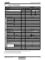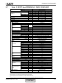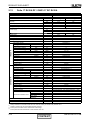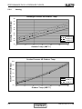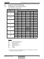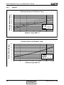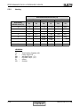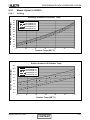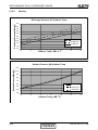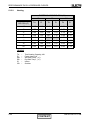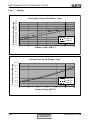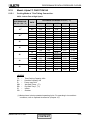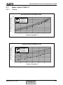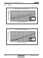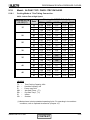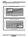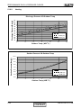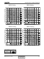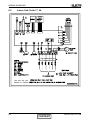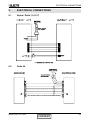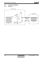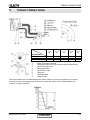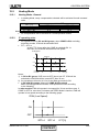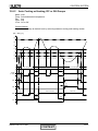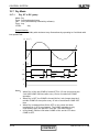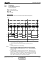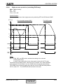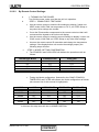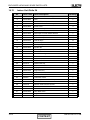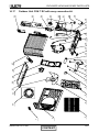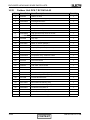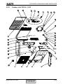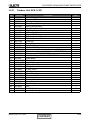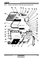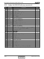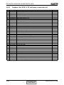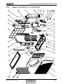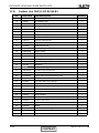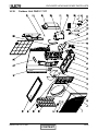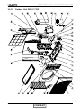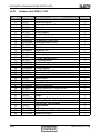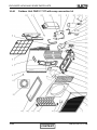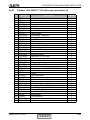
1
Service Manual
Alpha / Delta Series
Indoor Units
Alpha 7
Delta 7
Alpha 9
Delta 9 DF
Alpha 12
Delta 12 DF
Alpha 17
Alpha 17
Delta 17 DF
Delta 24
Outdoor Units
CON 7 (Alpha)
GCN 7
GCN 9 (Alpha)
ONG3-9 B1
ONG3-9 B2
GCN 12 (Alpha)
ONG3-12 B1
ONG3-12 B2
ONG3-14 B1
ONG3-17 (Alpha)
ONG3-17
OU7-24C
REFRIGERANT
COOLING ONLY
R410A
HEAT PUMP
SM ALPHA 1-E.3 GB
JULY 2008
CONTENT
LIST OF EFFECTIVE PAGES
LIST OF EFFECTIVE PAGES
Note: Changes in the pages are indicated by a “Revision#” in the footer of each effected page
(when none indicates no changes in the relevant page). All pages in the following list represent
effected/ non effected pages divided by chapters.
Dates of issue for original and changed pages are:
Original ....... 0 ........ 10 December 2004
Total number of pages in this publication is 169 consisting of the following:
Page
No.
Revision
No. #
Page
No.
Revision
No. #
Page
No.
Revision
No. #
Title ....................... 3
A ........................... 3
i ............................. 3
1-1 - 1-2 ................ 3
2-1 - 2-13 .............. 3
3-1 ........................ 3
4-1 - 4-6 ................ 3
5-1 - 5-40 .............. 3
6-1 - 6-8 ................ 3
7-1 ........................ 3
8-1 - 8-5 ................ 3
9-1 ........................ 3
10-1-10-4 .............. 3
11-1 ....................... 3
12-1-12-32 ............ 3
13-1-13-2 .............. 3
14-1-14-49 ............ 3
Appendix -A ...........3
• Zero in this column indicates an original page.
*Due to constant improvements please note that the data on this service manual can be modified with out notice.
**Photos are not contractual
A
CONTENT
SM ALPHA 1-E.3 GB
TABLE OF CONTENTS
Table of Contents
1.
INTRODUCTION ...................................................................................................1-1
2.
PRODUCT DATA SHEET ......................................................................................2-1
3.
RATING CONDITIONS ..........................................................................................3-1
4.
OUTLINE DIMENSIONS .......................................................................................4-1
5.
PERFORMANCE DATA & PRESSURE CURVES ................................................5-1
6.
SOUND LEVEL CHARACTERISTICS ..................................................................6-1
7.
ELECTRICAL DATA ..............................................................................................7-1
8.
WIRING DIAGRAMS .............................................................................................8-1
9.
ELECTRICAL CONNECTIONS .............................................................................9-1
10. REFRIGERATION DIAGRAMS .............................................................................10-1
11.
TUBING CONNECTIONS......................................................................................11-1
12. CONTROL SYSTEM .............................................................................................12-1
13. TROUBLESHOOTING ..........................................................................................13-1
14. EXPLODED VIEWS AND SPARE PARTS LISTS .................................................14-1
15. APPENDIX A .........................................................................................................15-1
SM ALPHA 1-E.3 GB
i
INTRODUCTION
1.
INTRODUCTION
1.1
General
The new Alpha / Delta split wall mounted is based on the compact range. It comprise
the ST (cooling only) and RC (heat pump) models,
The indoor Alpha / Delta units are available as LED display types, featuring esthetic
design, compact dimensions, and low noise operation.
1.2
Main Features
The Alpha / Deltaseries benefits from the most advanced technological innovations,
namely:
● R410A models
● Microprocessor control.
● Infrared remote control with liquid crystal display.
● Indoor large diameter cross flow fan, allowing low noise level operation.
● Bended indoor coil with treated aluminum fins and coating for improved
efficiency.
● High COP.
● Easy access to the interconnecting tubing and wiring connections, so that
removing the front grill or casing is not necessary.
● Refrigerant pipes can be connected to the indoor unit from 5 different optional
directions.
● Automatic treated air sweep.
● Easy installation and service.
● 4M length tubing connection kit is provided in the outdoor unit (optional).
1.3
Indoor Unit
The indoor unit is wall mounted, and can be easily fitted to many types of residential
and commercials applications.
It includes:
● Casing with air inlet and outlet grills.
● A large-diameter tangential fan.
● Bended coil with treated aluminum fins.
● Motorized flaps
● Multi-speed motor with internal protection
● Advanced electronic control box assembly
● Interconnecting wiring terminal block
● Mounting plate
SM ALPHA 1-E.3 GB
CONTENT
1-1
INTRODUCTION
1.4
Filtration
The Alpha / Delta series presents several types of air filters
● Easily accessible, and re-usable pre-filters (mesh)
● Pre-charged electrostatic filter (optional)
● Active carbon filter (optional)
1.5
Control
The microprocessor indoor controller, and an infrared remote control, supplied as
standard, provide complete operating function and programming. For further details
please refer to the Operation Manual, Appendix A.
1.6
Outdoor Unit
The Alpha / Delta outdoor units can be installed as floor or wall mounted units by using
a wall supporting bracket. The metal sheets are protected by anti- corrosion paint work
allowing long life resistance. All outdoor units are pre-charged. For further information
please refer to the Product Data Sheet, Chapter 2.
It includes :
● A Rotary compressor mounted in a soundproofed compartment :
● Axial fan.
● Outdoor coil with hydrophilic louver fins for RC units.
● Outlet air fan grill.
● Service valves” flare” type connection.
● Interconnecting wiring terminal block.
1.7
Tubing Connections
Flare type interconnecting tubing can be produced on site.
A connection pipe kit is provided in outdoor package.
For further details please refer to the Installation Manual, Appendix A.
1.8
Accessories
ASK (All Season Kit):
For low ambient working conditions in cooling, an ASK can be installed inside the outdoor
unit. This kit allows cooling operation down to outdoor temp of -10 ºC by gradually
controlling the outdoor fan speed motor.
1.9
Inbox Documentation
Each unit is supplied with its own installation and operation manuals.
1-2
CONTENT
SM ALPHA 1-E.3 GB
PRODUCT DATA SHEET
2.
PRODUCT DATA SHEET
2.1
Alpha 7 / CON7 (Alpha)
Model Indoor Unit
Model Outdoor Unit
Installation Method of Pipe
Characteristics
Capacity (1)
OUTDOOR
INDOOR
Power input (1)
EER (Cooling) or COP(Heating) (1)
Energy efficiency class
Power supply
Rated current
Starting current
Circuit breaker rating
Fan type & quantity
Fan speeds
H/M/L
H/M/L
Air flow (2)
External static pressure
Min-Max
Sound power level (3)
H/M/L
Sound pressure level(4)
H/M/L
Moisture removal
Condenstate drain tube I.D
Dimensions
WxHxD
Weight
Package dimensions
WxHxD
Packaged weight
Units per pallet
Stacking height
Refrigerant control
Compressor type, model
Fan type & quantity
Fan speeds
H/L
Air flow
H/L
Sound power level
H/L
Sound pressure level(4)
H/L
Dimensions
WxHxD
Weight
Package dimensions
WxHxD
Packaged weight
Units per pallet
Stacking height
Refrigerant type
Refrigerant chargless distance
Additional charge
Liquid line
Suction line
Connections between
Max.tubing length
units
Max.height difference
Operation control type
Heating elements
Others
(1)
(2)
(3)
(4)
Kg/m
kg
In.(mm)
In.(mm)
m.
Alpha 7
CON 7 (Alpha)
Flared
Cooling Only
Cooling
Heating
7000
7000
7300
2.05
2.05
2.15
0.68
0.68
0.63
3.01
3.01
3.41
B
B
B
230V/Single/50Hz
3.0
3.0
2.8
15
10
Crossflow x 1
1150/950
390/320
0
50/44
37/32
0.8
16
680*250*180
7
740*250*310
9.5
36
9 levels
Capillary tube
Rotary,TOSHIBA,PA82X1C-4DZDE
Propeller(direct) x 1
850
1200
61
62
52
53
610*235*490
27
27.5
720*550*360
30/33.5(with kit)
30.5/34(with kit)
12
4 levels
R410A
0.72kg/7.5m
4m≤length≤10m,0.72kg; 10m<length≤15m,0.8kg
Ф 1/4”(6.35)
Ф 3/8”(9.53)
Max.15
m.
Max.7
Units
Btu/hr
kW
kW
W/W
V/Ph/Hz
A
A
A
RPM
m3/hr
Pa
dB(A)
dB(A)
l/hr
mm
mm
kg
mm
kg
units
units
RPM
m3/hr
dB(A)
dB(A)
mm
kg
mm
kg
Units
units
Remote control
kW
Rating conditions in accordance with ISO 5151 and ISO 13253 (for ducted units) and EN 14511.
Airflow in ducted units; at nominal external static pressure.
Sound power in ducted units is measured at air discharge.
Sound pressure level measured at 1 meter distance from unit.
SM ALPHA 1-E.3 GB
CONTENT
2-1
PRODUCT DATA SHEET
2.2
Delta 7 R410A А2 DF / GCN 7 RC R410A A2
Model Indoor Unit
Model Outdoor Unit
Installation Method of Pipe
Characteristics
Units
Btu/hr
kW
kW
W/W
Capacity (4)
Power input (4)
EER (Cooling) or COP(Heating) (4)
Energy efficiency class(SII)
Power supply
OUTDOOR
INDOOR
Rated current
Power factor
Prated (IDU)
Prated (IDU+ODU)
Starting current
Circuit breaker rating
Fan type & quantity
Fan speeds
H/M/L
Air flow (1)
H/M/L
External static pressure
Min
Sound power level (2)
H/M/L
Sound pressure level(3)
H/M/L
Moisture removal
Condenstate drain tube I.D
Dimensions
WxHxD
Net Weight
Package dimensions
WxHxD
Packaged weight
Units per pallet
Stacking height
Refrigerant control
Compressor type,model
Fan type & quantity
Fan speeds
H
Air flow
H
Sound power level
H
Sound pressure level(3)
H
Dimensions
WxHxD
Net Weight
Package dimensions
WxHxD
Packaged weight
Units per pallet
Stacking height
Refrigerant type
Refrigerant chargless distance
Additional charge
Liquid line
Suction line
Connections between
Max.tubing length
units
Max.height
difference
Operation control type
Heating elements(Option)
Others
(1)
(2)
(3)
(4)
V
Ph
Hz
A
W
W
A
A
RPM
m3/hr
Pa
dB(A)
dB(A)
l/hr
mm
mm
kg
mm
kg
units
units
RPM
m3/hr
dB(A)
dB(A)
mm
kg
mm
kg
Units
units
kg(7.5m)
In.(mm)
In.(mm)
m.
Delta 7 R410A A2 DF
GCN 7 RC R410A A2
Flared
Cooling
Heating
7780
7850
2.28
2.30
0.62
0.67
3.70
3.45
A
A
230
1
50
2.8
3.0
0.95
0.95
30
890
15
10
Crossflow x 1
1050/-/900
450/-/380
0
50/-/44
37/-/31
0.74
16
680x250x180
6
740x310x248
8.5
32
8 levels
Capillary tube
Rotary,Toshiba(GMCC),PA82X1C-4DZDE
Propeller(direct) x 1
830
1450
60
50
830x545x245
31.5
870x600x320
34
12
3 levels
R410A
0.8kg
4m≤Length≤10m: +0g; 10m Length≤15m: +50g
1/4"(6.35)
3/8"(9.53)
Max.15
m.
Max.7
Remote control
kW
Rating conditions in accordance with ISO 5151 and ISO 13253 (for ducted units) and EN 14511.
Airflow in ducted units; at nominal external static pressure.
Sound power in ducted units is measured at air discharge.
Sound pressure level measured at 1 meter distance from unit.
2-2
CONTENT
SM ALPHA 1-E.3 GB
PRODUCT DATA SHEET
2.3
Alpha 9 / GCN9 (Alpha)
Model Indoor Unit
Model Outdoor Unit
Installation Method of Pipe
Characteristics
Capacity
Units
Btu/hr
kW
kW
W/W
(1)
OUTDOOR
INDOOR
Power input (1)
EER (Cooling) or COP(Heating) (1)
Energy efficiency class
Power supply
Rated current
Starting current
Circuit breaker rating
Fan type & quantity
Fan speeds
Air flow (2)
External static pressure
Sound power level (3)
Sound pressure level(4)
Moisture removal
Condenstate drain tube I.D
Dimensions
Weight
Package dimensions
Packaged weight
Units per pallet
Stacking height
Refrigerant control
Compressor type,model
Fan type & quantity
Fan speeds
Air flow
Sound power level
Sound pressure level(4)
Dimensions
Weight
Package dimensions
Packaged weight
Units per pallet
Stacking height
Refrigerant type
Refrigerant chargless distance
V/Ph/Hz
A
A
A
H/M/L
H/M/L
Min-Max
H/M/L
H/M/L
Operation control type
Heating elements
Others
(1)
(2)
(3)
(4)
9000
2.64
0.87
3.03
B
3.9
RPM
m3/hr
Pa
dB(A)
dB(A)
l/hr
mm
mm
kg
mm
kg
units
units
WxHxD
WxHxD
Heating
9000
2.64
0.87
3.03
B
9650
2.83
0.93
3.04
D
230V/Single/50Hz
3.9
21.7
10
Crossflow x 1
1310/1100
450/360
0
53/49
41/35
1.2
16
680*250*180
7
740*250*310
9.5
36
9 levels
Capillary tube
4.1
Rotary,TOSHIBA,PA108X1C-4FZDE
H/L
H/L
H/L
H/L
WxHxD
RPM
m3/hr
dB(A)
dB(A)
mm
kg
mm
kg
Units
units
WxHxD
kg/m
Additional charge
Connections between
units
Alpha 9
GCN 9 (Alpha)
Flared
Cooling Only
Cooling
kg
Liquid line
Suction line
Max.tubing length
Max.height difference
In.(mm)
In.(mm)
m.
m.
Propeller(direct) x 1
750
1370
59
49
61
51
830x245x545
32.5
33.5
880x320x610
35/38.5(with kit)
36/39.5(with kit)
9
3levels
R410A
0.85kg/7.5m
0.9kg/7.5m
4m≤length≤10m,0.85kg
4m≤length≤10m,0.9kg
10m<length≤15m,0.93kg 10m<length≤15m,0.98kg
Ф 1/4”(6.35)
Ф 3/8”(9.53)
Max.15
Max.7
Remote control
kW
Rating conditions in accordance with ISO 5151 and ISO 13253 (for ducted units). and EN 14511
Airflow in ducted units; at nominal external static pressure.
Sound power in ducted units is measured at air discharge.
Sound pressure level measured at 1 meter distance from unit.
SM ALPHA 1-E.3 GB
CONTENT
2-3
PRODUCT DATA SHEET
2.4
Delta 9 RC/ST fixed RPM R410A / ONG3-9 R410A B1
Model
Indoor unit
Outdoor unit
Characteristics
Total
Capacity (4)
Sensible capacity
Moisture removal
OUTDOOR
INDOOR
Power input (4)
EER (Cooling) or COP(Heating) (4)
Power supply
Running Current (Rated)
Starting current
Circuit breaker rating
Model
Fan type & quantity
H/M/L
Fan speeds
H
Air flow (1)
M
L
Area
Coil
Rows
Fin Spacing
External static pressure
Nom
Airflow direction control
Air Filter
Running Current (Rated)
Power level (H/M/L)
Sound
Pressure level(3) (H/M/L
Cooling Temperature Operating Range (Min/Max)
Heating Temperature Operating Range (Min/Max)
Condenstate drain tube I.D
Dimensions/(packaged)
WxDxH
Weight
Model
Type
Model
Compressor
Motor kW
Running Current (Rated)
Motor Speed
Type
Blades
Diameter
Fan
Air flow
Motor Type
Speed (H/L)
Motor output
Area
Rows
Coil
Fin Spacing
Power level (H/L)
Sound
Pressure level(3) (H/L)
Cooling Temperature Operating Range (Min/Max)
Heating Temperature Operating Range (Min/Max)
Dimensions/(packaged)
WxDxH
Weight(packaged)
Type
Control
Refrigerant
Chargless distance
Add charge per mtr
Liquid line
Suction line
Connections between
Type
units
Max.tubing length
Max.height difference
Operation control type
Heating elements (Option)
Others
Units
Btu/hr
kW
kW
l/hr
kW
W/W
V/Ph/Hz
A
A
A
RPM
L/S
M2
Qty
mm
Pa
amp
dB(A)
dB(A)
mm
mm
kg
watt
amp
RPM
Qty
mm
m3/hr
RPM
watt
M2
Qty
mm
dB(A)
dB(A)
mm
kg
kg/m
g/m
In.(mm)
In.(mm)
m.
m.
kW
Delta 9RC/ST fixed rpm R410A
ONG3-9 R410A B1
Cooling
Heating
Cooling Only
8870
9720
8870
2.6
2.85
2.6
1940
1940
0.98
0.98
0.78
0.850
0.78
3.35
3.34
3.34
220-240V/Single/50Hz
3.8
3.5
3.5
21.7
10
Delta 9RC/ST fixed rpm R410A
Centifugal x1
1310/-/1100
125
100
0.126
2
1.5
0
supplied by others
0.13
53/-/49
41/-/35
21°C DB (15 °C WB) / 32°C DB (23°C WB)
10°C /27°C
16
680*250*180 / 740*310*248
9.5
ONG3-9 R410A B1
Single Rotary
PA103X1C-4DZDE
840/870
3.90/3.80
3000
Propeller(direct) x 1
3
400
1750
fixed RPM
730
20
0.45
2
1.5
60 / 49 / 21°C/ 46°C
-9°C / 24°C
795*610*290 / 970*650*394
33 / 35.5
32 / 34.5
R410A
Capillary tube
0.91kg/7.5m
4m<L≤10m: +0g; 10m<L≤15m: +80g
1/4"(6.35)
3/8"(9.53)
Flared
Max15
Max.8
RC7 Remote control
-
(1) Airflow in ducted units;at nominal external static pressure.
(2)
Sound power in ducted units is measured at air discharge.
(3)
Sound pressure level measured at 1-meter distance from unit.
(4)
Rating conditions in accordance to AS 3823, ISO 5151 and ISO 13253 (for ducted units).
2-4
CONTENT
SM ALPHA 1-E.3 GB
PRODUCT DATA SHEET
2.5
Delta 9 R410A B2 DF / ONG3-9 RC R410A B2 ISR
Model Indoor Unit
Model Outdoor Unit
Installation Method of Pipe
Characteristics
Units
Btu/hr
kW
kW
W/W
Capacity (4)
Power input (4)
EER (Cooling) or COP(Heating) (4)
Energy efficiency class(SII)
Power supply
OUTDOOR
INDOOR
Rated current
Power factor
Prated (IDU)
Prated (IDU+ODU)
Starting current
Circuit breaker rating
Fan type & quantity
Fan speeds
H/M/L
Air flow (1)
H/M/L
External static pressure
Min
Sound power level (2)
H/M/L
Sound pressure level(3)
H/M/L
Moisture removal
Condenstate drain tube I.D
Dimensions
WxHxD
Net Weight
Package dimensions
WxHxD
Packaged weight
Units per pallet
Stacking height
Refrigerant control
Compressor type,model
Fan type & quantity
Fan speeds
H
Air flow
H
Sound power level
H
Sound pressure level(3)
H
Dimensions
WxHxD
Net Weight
Package dimensions
WxHxD
Packaged weight
Units per pallet
Stacking height
Refrigerant type
Refrigerant chargless distance
Additional charge
Liquid line
Suction line
Connections between
Max.tubing length
units
Max.height
difference
Operation control type
Heating elements(Option)
Others
(1)
(2)
(3)
(4)
V
Ph
Hz
A
W
W
A
A
RPM
m3/hr
Pa
dB(A)
dB(A)
l/hr
mm
mm
kg
mm
kg
units
units
RPM
m3/hr
dB(A)
dB(A)
mm
kg
mm
kg
Units
units
kg(7.5m)
In.(mm)
In.(mm)
m.
Delta 9 R410A B2 DF ISR
ONG3-9 RC R410A B2 ISR
Flared
Cooling
Heating
9210
9890
2.70
2.90
0.75
0.83
3.60
3.50
C
C
230
1
50
3.4
3.8
0.95
0.95
30
1050
16.6
10
Crossflow x 1
1320/-/1100
450/-/360
0
53/-/49
41/-/35
1.02
16
680x250x180
6
740x310x248
8.5
32
8 levels
Capillary tube
Rotary,Toshiba(GMCC),PA103X1C-4FZDE1
Propeller(direct) x 1
780
1800
59
49
795x610x290
33
970x650x394
35.5
9
3 levels
R410A
0.95kg
4m≤Length≤10m: +0g; 10m≤Length≤15m: +50g
1/4"(6.35)
3/8"(9.53)
Max.15
m.
Max.7
Remote control
kW
Rating conditions in accordance with ISO 5151 and ISO 13253 (for ducted units) and EN 14511.
Airflow in ducted units; at nominal external static pressure.
Sound power in ducted units is measured at air discharge.
Sound pressure level measured at 1 meter distance from unit.
SM ALPHA 1-E.3 GB
CONTENT
2-5
PRODUCT DATA SHEET
2.6
Alpha 12 / GCN12 (Alpha)
Model Indoor Unit
Model Outdoor Unit
Installation Method of Pipe
Characteristics
Units
Btu/hr
kW
kW
W/W
Capacity (1)
OUTDOOR
INDOOR
Power input (1)
EER (Cooling) or COP(Heating) (1)
Energy efficiency class
Power supply
Rated current
Starting current
Circuit breaker rating
Fan type & quantity
Fan speeds
Air flow (2)
External static pressure
Sound power level (3)
Sound pressure level(4)
Moisture removal
Condenstate drain tube I.D
Dimensions
Weight
Package dimensions
Packaged weight
Units per pallet
Stacking height
Refrigerant control
Compressor type,model
Fan type & quantity
Fan speeds
Air flow
Sound power level
Sound pressure level(4)
Dimensions
Weight
Package dimensions
Packaged weight
Units per pallet
Stacking height
Refrigerant type
Refrigerant chargless distance
V/Ph/Hz
A
A
A
H/M/L
H/M/L
Min-Max
H/M/L
H/M/L
WxHxD
WxHxD
H/L
H/L
H/L
H/L
WxHxD
RPM
m3/hr
dB(A)
dB(A)
mm
kg
mm
kg
Units
units
WxHxD
kg/m
Additional charge per 1 meter
Connections between
units
Operation control type
Heating elements
Others
(1)
(2)
(3)
(4)
RPM
m3/hr
Pa
dB(A)
dB(A)
l/hr
mm
mm
kg
mm
kg
units
units
g/m
Liquid line
Suction line
Max.tubing length
Max.height
difference
In.(mm)
In.(mm)
m.
Alpha 12
GCN 12 (Alpha)
Flared
Cooling Only
Cooling
12000
3.50
1.16
3.02
B
5.2
12000
3.50
1.16
3.02
B
230V/Single/50Hz
5.2
31.5
10
Crossflow x 1
1210/950
620/460
0
53/47
40/33
1.5
16
840*250*180
8
900*250*310
11
36
9 levels
Heating
12900
3.78
1.17
3.23
C
5.2
Capillary tube
Rotary,TOSHIBA,PA145X2C-4FT
Propeller(direct) x 1
830
1450
65
65
54
54
830x245x545
37
38
880x320x610
39.5/43(with kit)
40.5/44(with kit)
9
3 levels
R410A
0.89kg/7.5m
4m≤length≤10m,0.89kg
10m<length≤15m,0.97kg
Ф1/4”(6.35)
ø3/8”(9.53)
Max.15
m.
Max.7
Remote control
kW
Rating conditions in accordance with ISO 5151 and ISO 13253 (for ducted units) and EN 14511.
Airflow in ducted units; at nominal external static pressure.
Sound power in ducted units is measured at air discharge.
Sound pressure level measured at 1 meter distance from unit.
2-6
CONTENT
SM ALPHA 1-E.3 GB
PRODUCT DATA SHEET
2.7
Delta 12 RC/ST fixed RPM R410A / ONG3-12 R410A B1
Model
Indoor unit
Delta 12RC/ST fixed rpm R410A
Outdoor unit
Characteristics
Total
Capacity (4)
Sensible capacity
Moisture removal
OUTDOOR
INDOOR
Power input (4)
EER (Cooling) or COP(Heating) (4)
Power supply
Running Current (Rated)
Starting current
Circuit breaker rating
Model
Fan type & quantity
H/M/L
Fan speeds
H
Air flow (1)
M
L
Area
Coil
Rows
Fin Spacing
External static pressure
Nom
Airflow direction control
Air Filter
Running Current (Rated)
Power level (H/M/L)
Sound
Pressure level(3) (H/M/
Cooling Temperature Operating Range (Min/Max)
Heating Temperature Operating Range (Min/Max)
Condenstate drain tube I.D
Dimensions/(packaged)
WxDxH
Weight
Model
Type
Model
Compressor
Motor kW
Running Current (Rated
Motor Speed
Type
Blades
Diameter
Fan
Air flow
Motor Type
Speed (H/L)
Motor output
Area
Coil
Rows
Fin Spacing
Power level (H/L)
Sound
Pressure level(3) (H/L)
Cooling Temperature Operating Range (Min/Max)
Heating Temperature Operating Range (Min/Max)
Dimensions/(packaged)
WxDxH
Weight(packaged)
Type
Control
Refrigerant
Chargless distance
Add charge per mtr
Liquid line
Suction line
Connections between
Type
units
Max.tubing length
Max.height difference
Operation control type
Heating elements (Option)
Others
Units
Btu/hr
kW
kW
l/hr
kW
W/W
V/Ph/Hz
A
A
A
RPM
L/S
M2
Qty
mm
Pa
amp
dB(A)
dB(A)
mm
mm
kg
watt
amp
RPM
Qty
mm
m3/hr
RPM
watt
M2
Qty
mm
dB(A)
dB(A)
mm
kg
kg/m
g/m
In.(mm)
In.(mm)
m.
m.
kW
ONG3-12 R410A B1
Cooling
Heating
12280
11260
3.60
3.3
2.585
1.05
1.030
1.01
3.26
3.47
220-240V/Single/50Hz
4.6
4.7
4.6
24
10
Delta 12RC/ST fixed rpm R410A
Centifugal x1
1210/-/950
172
127
0.167
2
1.5
0
supplied by others
0.13
53/-/47
40/-/33
21 °C DB (15°C WB) / 32°C DB (23°C WB)
10 °C ~27 °C
16
840*250*180 / 900*310*248
10.5
ONG3-12 R410A B1
Single Rotary
PANSONIC, 5PS132EAA22
1085/1115
5.05/4.85
3000
Propeller(direct) x 1
3
400
1850
Fixed RPM
810
25
0.45
2
1.5
61/50/21 °C / 46 °C
-9 °C / 24 °C
795*610*290 / 970*650*394
34.5 / 37
33.5 / 36
R410A
Capillary tube
0.93kg/7.5m
4m<L≤10m: +0g; 10m<L≤15m: +80g
1/4"(6.35)
3/8"(9.53)
Flared
Max15
Max.8
RC7 Remote control
-
Cooling Only
11260
3.3
2.585
1.05
1.01
3.26
(1) Airflow in ducted units;at nominal external static pressure.
(2)
Sound power in ducted units is measured at air discharge.
(3)
Sound pressure level measured at 1-meter distance from unit.
(4)
Rating conditions in accordance to AS 3823, ISO 5151 and ISO 13253 (for ducted units).
SM ALPHA 1-E.3 GB
CONTENT
2-7
PRODUCT DATA SHEET
2.8
Delta 12 R410A B2 DF / ONG3-12 RC R410A B2 ISR
Model Indoor Unit
Model Outdoor Unit
Installation Method of Pipe
Characteristics
Power input (4)
EER (Cooling) or COP(Heating) (4)
Energy efficiency class(SII)
INDOOR
m.
Max.7
V
Ph
Hz
A
Power supply
OUTDOOR
In.(mm)
In.(mm)
m.
Units
Btu/hr
kW
kW
W/W
Capacity (4)
Rated current
Power factor
Prated (IDU)
Prated (IDU+ODU)
Starting current
Circuit breaker rating
Fan type & quantity
Fan speeds
Air flow (1)
External static pressure
Sound power level (2)
Sound pressure level(3)
Moisture removal
Condenstate drain tube I.D
Dimensions
Net Weight
Package dimensions
Packaged weight
Units per pallet
Stacking height
Refrigerant control
Compressor type,model
Fan type & quantity
Fan speeds
Air flow
Sound power level
Sound pressure level(3)
Dimensions
Net Weight
Package dimensions
Packaged weight
Units per pallet
Stacking height
Refrigerant type
Refrigerant chargless distance
Delta 12 R410A B2 DF ISR
ONG3-12 RC R410A B2 ISR
Flared
Cooling
Heating
12110
12620
3.55
3.70
0.99
1.03
3.60
3.60
A
A
230
1
50
4.5
4.7
0.95
0.95
30
1430
24
10
Crossflow x 1
1250/-/880
620/-/390
0
53/-/47
40/-/33
1.26
16
840x250x180
8
900x310x248
10.5
32
8 levels
Capillary tube
Rotary,Panasonic,5PS132EAC22
Propeller(direct) x 1
810
1850
62
52
795x610x290
34.5
970x650x394
37
9
3 levels
R410A
0.98kg
4m≤Length≤10m: +0g; 10m≤Length≤15m:
+70g
1/4"(6.35)
3/8"(9.53)
Max.15
W
W
A
A
H/M/L
H/M/L
Min
H/M/L
H/M/L
WxHxD
WxHxD
H
H
H
H
WxHxD
WxHxD
RPM
m3/hr
Pa
dB(A)
dB(A)
l/hr
mm
mm
kg
mm
kg
units
units
RPM
m3/hr
dB(A)
dB(A)
mm
kg
mm
kg
Units
units
kg(7.5m)
Additional charge
Connections between units
Operation control type
Heating elements (Option)
Others
(1)
(2)
(3)
(4)
Liquid line
Suction line
Max.tubing length
Max.height
difference
Remote control
kW
Rating conditions in accordance with ISO 5151 and ISO 13253 (for ducted units) and EN 14511.
Airflow in ducted units; at nominal external static pressure.
Sound power in ducted units is measured at air discharge.
Sound pressure level measured at 1 meter distance from unit.
2-8
CONTENT
SM ALPHA 1-E.3 GB
PRODUCT DATA SHEET
2.9
Delta 17 R410A B1 DF / ONG3-14 RC R410A B1 ISR
Model Indoor Unit
Model Outdoor Unit
Installation Method of Pipe
Characteristics
Units
Btu/hr
kW
kW
W/W
Capacity (4)
Power input (4)
EER (Cooling) or COP(Heating) (4)
Energy efficiency class(SII)
V
Ph
Hz
A
Power supply
OUTDOOR
INDOOR
Rated current
Power factor
Prated (IDU)
Prated (IDU+ODU)
Starting current
Circuit breaker rating
Fan type & quantity
Fan speeds
Air flow (1)
External static pressure
Sound power level (2)
Sound pressure level(3)
Moisture removal
Condenstate drain tube I.D
Dimensions
Net Weight
Package dimensions
Packaged weight
Units per pallet
Stacking height
Refrigerant control
Compressor type,model
Fan type & quantity
Fan speeds
Air flow
Sound power level
Sound pressure level(3)
Dimensions
Net Weight
Package dimensions
Packaged weight
Units per pallet
Stacking height
Refrigerant type
Refrigerant chargless distance
Additional charge
Connections between units
Operation control type
Heating elements (Option)
Others
(1)
(2)
(3)
(4)
W
W
A
A
H/M/L
H/M/L
Min
H/M/L
H/M/L
WxHxD
WxHxD
H
H
H
H
WxHxD
WxHxD
RPM
m3/hr
Pa
dB(A)
dB(A)
l/hr
mm
mm
kg
mm
kg
units
units
RPM
m3/hr
dB(A)
dB(A)
mm
kg
mm
kg
Units
units
kg(7.5m)
Liquid line
Suction line
Max.tubing length
Max.height difference
In.(mm)
In.(mm)
m.
m.
DELTA 17 R410A B1 DF ISR
ONG3-14 RC R410A B1 ISR
Flared
Cooling
Heating
16040
16720
4.70
4.90
1.40
1.40
3.38
3.50
C
C
230
1
50
6.4
6.4
0.95
0.95
42
1830
28.4
15
Crossflow x 1
1200/ - /1000
720/ - /590
0
55/-/50
43/ - /37
1.75
16
900x295x200
11
955x360x270
14
24
8 levels
Capillary tube
Rotary,Panasonic,5KS170EAB21
Propeller(direct) x 1
910
2160
64
53
795x610x290
40.5
970x650x394
43
9
3 levels
R410A
1.27kg
4m≤Length≤10m: +0g; 10m≤Length≤15m: +150g
1/4"(6.35)
1/2"(12.7)
Max.15
Max.7
Remote control
kW
Rating conditions in accordance with ISO 5151 and ISO 13253 (for ducted units) and EN 14511.
Airflow in ducted units; at nominal external static pressure.
Sound power in ducted units is measured at air discharge.
Sound pressure level measured at 1 meter distance from unit.
SM ALPHA 1-E.3 GB
CONTENT
2-9
PRODUCT DATA SHEET
2.10
Alpha 17 / ONG3-17 (Alpha)
Model Indoor Unit
Model Outdoor Unit
Alpha 17
ONG3 17 (Alpha)
Installation Method of Pipe
Flared
Characteristics
Capacity (1)
Units
cooling only
Cooling
Heating
Btu/hr
17570
5.15
1.70
3.03
B
17570
5.15
1.70
3.03
B
18250
5.35
1.65
3.24
C
kW
Power input (1)
kW
EER (Cooling) or COP(Heating) (1)
W/W
Energy efficiency class
Power supply
V/Ph/Hz
Rated current
A
Starting current
A
Circuit breaker rating
A
230V/Single/50Hz
7.6
7.6
15
Fan type & quantity
INDOOR
Cross flow x 1
Fan speeds
H/M/L
RPM
1200/1000
Air flow (2)
H/M/L
m3/hr
720/590
Min-Max
Pa
0
Sound power level (3)
H/M/L
dB(A)
55-50
Sound pressure level(4)
H/M/L
External static pressure
dB(A)
43-37
Moisture removal
l/hr
2.2
Condensate drain tube I.D
mm
16
WxHxD
mm
900x295x200
kg
11
WxHxD
mm
955x360x270
kg
14
Dimensions
Weight
Package dimensions
Packaged weight
Units per pallet
units
24
Stacking height
units
8 levels
Refrigerant control
Capillary tube
Compressor type, model
Rotary,TOSHIBA,PA200X2CS-4KT1
Fan type & quantity
Propeller(direct) x 1
Fan speeds
H/L
RPM
910
Air flow
H/L
m3/hr
2160
Sound power level
H/L
dB(A)
64
Sound pressure level(4)
H/L
dB(A)
53
WxHxD
mm
WxHxD
mm
Dimensions
OUTDOOR
Weight
Package dimensions
kg
Packaged weight
kg
65
54
795x290x610
42
43
945x395x655
45/49(with kit)
Units
9
Stacking height
units
3 levels
Refrigerant chargless distance
kg/m
Additional charge per 1 meter
g/m
Refrigerant type
R410A
Liquid line
In.(mm)
1.28/7.5
4m ≤ L ≤10M:0g
10m ≤ L ≤15M:+100g
ø1/4”(6.35)
Suction line
In.(mm)
ø 1/2”(12.7)
Max.tubing length
m.
Max.15
Max.height difference
m.
Max.7
Operation control type
Heating elements
Others
(1)
(2)
(3)
(4)
46/50(with kit)
Units per pallet
Connections between units
7.4
30
Remote Control
kW
ASK Factory Option
Rating conditions in accordance with ISO 5151 and ISO 13253 (for ducted units) and EN 14511.
Airflow in ducted units; at nominal external static pressure.
Sound power in ducted units is measured at air discharge.
Sound pressure level measured at 1 meter distance from unit.
2-10
CONTENT
SM ALPHA 1-E.3 GB
PRODUCT DATA SHEET
2.11
Delta 17 RC/ST fixed RPM R410A / ONG3-17 (Alpha)
Delta 17RC/ST fixed rpm R410A
Model Indoor Unit
Model Outdoor Unit
ONG3 17 (Alpha)
Installation Method of Pipe
Flared
Characteristics
Capacity (1)
Units
cooling only
Cooling
Heating
Btu/hr
17570
5.15
1.70
3.03
B
17570
5.15
1.70
3.03
B
18250
5.35
1.65
3.24
C
kW
Power input (1)
kW
EER (Cooling) or COP(Heating) (1)
W/W
Energy efficiency class
Power supply
V/Ph/Hz
Rated current
A
Starting current
A
Circuit breaker rating
A
230V/Single/50Hz
7.6
15
INDOOR
Cross flow x 1
Fan speeds
H/M/L
RPM
1200/1000
Air flow (2)
H/M/L
m3/hr
720/590
Min-Max
Pa
0
Sound power level (3)
H/M/L
dB(A)
55-50
Sound pressure level(4)
H/M/L
External static pressure
dB(A)
43-37
Moisture removal
l/hr
2.2
Condensate drain tube I.D
mm
16
WxHxD
mm
900x295x205
kg
11
WxHxD
mm
955x360x270
kg
14
Dimensions
Weight
Package dimensions
Packaged weight
Units per pallet
units
24
Stacking height
units
8 levels
Refrigerant control
Capillary tube
Compressor type, model
Rotary,TOSHIBA,PA200X2CS-4KT1
Fan type & quantity
Propeller(direct) x 1
Fan speeds
H/L
RPM
910
Air flow
H/L
m3/hr
2160
Sound power level
H/L
dB(A)
64
Sound pressure level(4)
H/L
dB(A)
53
WxHxD
mm
WxHxD
mm
Dimensions
Weight
Package dimensions
kg
Packaged weight
kg
65
54
795x290x610
42
43
945x395x655
45/49(with kit)
46/50(with kit)
Units per pallet
Units
9
Stacking height
units
3 levels
Refrigerant chargless distance
kg/m
1.28/7.5
Additional charge per 1 meter
g/m
4m ≤ L ≤10M:0g
10m ≤ L ≤15M:+100g
Refrigerant type
Connections between units
R410A
Liquid line
In.(mm)
ø1/4”(6.35)
Suction line
In.(mm)
ø 1/2”(12.7)
m.
Max.15
m.
Max.7
Max.tubing length
Max.height
difference
Operation control type
Heating elements
Others
(1)
(2)
(3)
(4)
7.4
30
Fan type & quantity
OUTDOOR
7.6
Remote Control
kW
ASK Factory Option
Rating conditions in accordance with ISO 5151 and ISO 13253 (for ducted units) and EN 14511.
Airflow in ducted units; at nominal external static pressure.
Sound power in ducted units is measured at air discharge.
Sound pressure level measured at 1 meter distance from unit.
SM ALPHA 1-E.3 GB
CONTENT
2-11
PRODUCT DATA SHEET
2.12
Delta 17 R410A DF / ONG3-17 RC R410A
Model Indoor Unit
Model Outdoor Unit
Installation Method of Pipe
Characteristics
Units
Btu/hr
kW
kW
W/W
Capacity(4)
Power input(4)
EER (Cooling) or COP(Heating) (4)
Energy efficiency class(SII)
V
Ph
Hz
A
Power supply
Rated current
Power factor
Prated (IDU)
Prated (IDU+ODU)
Starting current
Circuit breaker rating
Fan type & quantity
Fan speeds
OUTDOOR
INDOOR
Air flow(1)
External static pressure
Sound power level(2)
Sound pressure level(3)
Moisture removal
Condenstate drain tube I.D
Dimensions
Net Weight
Package dimensions
Packaged weight
Units per pallet
Stacking height
Refrigerant control
Compressor type,model
Fan type & quantity
Fan speeds
Air flow
Sound power level
Sound pressure level(3)
Dimensions
Net Weight
Package dimensions
Packaged weight
Units per pallet
Stacking height
Refrigerant type
Refrigerant chargless distance
Additional charge
Connections between units
Operation control type
Heating elements (Option)
Others
(1)
(2)
(3)
(4)
W
W
A
A
H/M/L
H/M/L
Min
H/M/L
H/M/L
WxHxD
WxHxD
H
H
H
H
WxHxD
WxHxD
RPM
m3/hr
Pa
dB(A)
dB(A)
l/hr
mm
mm
kg
mm
kg
units
units
RPM
m3/hr
dB(A)
dB(A)
mm
kg
mm
kg
Units
units
kg(7.5m)
Liquid line
Suction line
Max.tubing length
Max.height
difference
In.(mm)
In.(mm)
m.
Delta 17 R410A DF
ONG3-17 RC R410A
Flared
Cooling
Heating
18430
18770
5.40
5.50
1.69
1.67
3.20
3.30
F
E
230
1
50
7.7
7.6
0.95
0.95
40
2150
32
15
Crossflow x 1
1200/ - /1000
720/ - /590
0
55/-/50
43/ - /37
2.33
16
900x295x200
11
955x360x270
14
24
8 levels
Capillary tube
Rotary,TOSHIBA PA200X2CS-4KT1
Propeller(direct) x 1
910
2160
65
54
795x610x290
43
970x650x394
46
9
3 levels
R410A
1.28kg
4m≤Length≤10m: +0g; 10m≤Length≤15m: +100g
1/4"(6.35)
1/2"(12.7)
Max.15
m.
Max.7
Remote control
kW
Rating conditions in accordance with ISO 5151 and ISO 13253 (for ducted units) and EN 14511.
Airflow in ducted units; at nominal external static pressure.
Sound power in ducted units is measured at air discharge.
Sound pressure level measured at 1 meter distance from unit.
2-12
CONTENT
SM ALPHA 1-E.3 GB
PRODUCT DATA SHEET
2.13
Delta 24 R410A / OU7-24C R410A
Model Indoor Unit
Model Outdoor Unit
Delta 24
OU7-24C
Installation method
WALL MOUNTED
Characteristics
Capacity(1)
Power input
(1)
COP(1)
Energy efficiency class
Units
Cooling only
Cooling
Heating
Btu/hr
23100
23100
24150
kW
6.77
6.77
7.08
kW
2.24
2.24
2.35
W/W
3.02
3.02
2.95
B
B
D
Power supply
V/ Ph /Hz
Rated current
A
Starting current
A
Circuit breaker rating
A
230/50/1
10.5
20
Fan type & quantity
CROSS FLOW *1
Fan speeds
H/ M/ L
RPM
1300
1200
1100
Air flow(2)
H/ M/ L
m_/hr
910
820
740
External static pressure
INDOOR
11.0
63
Min-Max
Pa
Sound power level(3)
H/ M/ L
dB(A)
60
57
55
Sound pressure level(4)
Moisture removal
H/ M/ L
dB(A)
47
44
42
L/hr
Condensate drain tube I.D
Dimensions
N/A
2.3
mm
W/ H / D
Weight
mm
16
1060
295
kg
Package dimensions
W/ H / D
Packaged weight
mm
1125
360
kg
18
Units per pallet
Units
16
Stacking height
Units
CAPILLARY TUBE
Compressor type, model
ROTARY
OUTDOOR
Fan type & quantity
AXIAL*1
Fan speeds
H/L
RPM
850
720
Air flow
H/L
m_/hr
3100
2600
Sound power level
H/L
dB(A)
67
62
Sound pressure level(4)
Dimensions
H/L
dB(A)
58
W/ H / D
mm
Weight
54
900
680
kg
Package dimensions
W/ H / D
Packaged weight
mm
985
730
kg
67
Units per pallet
Units
6
Stacking height
Units
2
Refrigerant chargless distance
kg/m
1.7 / 7.5
Additional charge
Connections
between units
g/m
7.5m<Add 30g / <15m
Liquid line
In.
3/8
Suction line
In.
5/8
Max. tubing length
m.
15
Max. height difference
m.
Heating elements
Others
(4)
406
R410A
Operation control type
(3)
340
64
Refrigerant type
(2)
280
8
Refrigerant control
(1)
210
15
7
LCD REMOTE CONTROL
kW
Rating conditions in accordance with ISO 5151 and ISO 13253 (for ducted units) and EN 14511.
Airflow in ducted units; at nominal external static pressure.
Sound power in ducted units is measured at air discharge.
Sound pressure level measured at 1 meter distance from unit.
SM ALPHA 1-E.3 GB
CONTENT
2-13
RATING CONDITIONS
3.
RATING CONDITIONS
Standard conditions in accordance with ISO 5151, ISO 13253 (for ducted units)
and EN 14511.
Cooling:
Indoor:
27oC DB 19oC WB
Outdoor: 35 oC DB
Heating:
Indoor:
20oC DB
Outdoor: 7oC DB 6oC WB
3.1
Operating Limits
3.1.1 R410A
Cooling
Heating
Indoor
Outdoor
Upper limit
Lower limit
Upper limit
32oC DB 23oC WB
21oC DB 15oC WB
27oC DB
46oC DB
10oC DB
24oC DB 18oC WB
Lower limit
10oC DB
-9oC DB -10oC WB
Voltage
SM ALPHA 1-E.3 GB
198 – 264 V
CONTENT
3-1
OUTLINE DIMENSIONS
4.
OUTLINE DIMENSIONS
4.1
Indoor Unit: Apha 7, 9 (Omega)
4.2
Indoor Unit: Alpha 12 (Omega)
SM ALPHA 1-E.3 GB
CONTENT
4-1
OUTLINE DIMENSIONS
4.3
Indoor Unit: Alpha 17
200
295
900
4.4
Indoor Unit: Alpha 9DF
680
250
180
4-2
CONTENT
SM ALPHA 1-E.3 GB
OUTLINE DIMENSIONS
4.5
Indoor Unit: Alpha 12DF
840
250
180
4.6
Indoor Unit: Delta 17F
SM ALPHA 1-E.3 GB
CONTENT
4-3
OUTLINE DIMENSIONS
4.7
4-4
Indoor Unit: Delta 24F
CONTENT
SM ALPHA 1-E.3 GB
OUTLINE DIMENSIONS
4.8
Outdoor Unit CON 7 (Alpha)
650
240
235
75
130
520
610
4.9
280
248
403
Outdoor Unit GCN 7, 9, 12 (Alpha)
830
760
545
245
472
260
50
237
AI R I NTAKE
AI R OUTLET
SM ALPHA 1-E.3 GB
CONTENT
4-5
OUTLINE DIMENSIONS
4.10
Outdoor Unit ONG3- 9, 12, 14, 17 (Alpha)
4.11
Outdoor Unit OU7-24C
4-6
CONTENT
SM ALPHA 1-E.3 GB
PERFORMANCE DATA & PRESSURE CURVES
5.
PERFORMANCE DATA & PRESSURE CURVES
5.1
Alpha7/CON7
5.1.1
Cooling Mode at 7.5m Tubing Connection.
230V : Indoor Fan at High Speed.
ENTERING AIR
DB OD Coil(oC)
15
(1)
20(1)
25
30
35
40
46
Data
TC
SC
PI
TC
SC
PI
TC
SC
PI
TC
SC
PI
TC
SC
PI
TC
SC
PI
TC
SC
PI
ENTERING AIR WB/DB ID Coil(oC)
15/21
17/24
19/27
21/29
23/32
2.16
2.24
2.29
2.34
2.38
1.49
1.55
1.61
1.65
1.68
0.48
0.48
0.48
0.49
0.49
2.09
2.20
2.27
2.33
2.38
1.46
1.54
1.60
1.65
1.68
0.52
0.53
0.53
0.53
0.53
1.98
2.14
2.25
2.31
2.37
1.42
1.51
1.59
1.64
1.67
0.57
0.57
0.57
0.58
0.58
1.85
2.01
2.18
2.25
2.32
1.38
1.46
1.56
1.60
1.63
0.62
0.61
0.62
0.63
0.64
1.71
1.86
2.15
2.25
2.05
1.31
1.40
1.52
1.56
1.59
0.68
0.66
0.67
0.69
0.69
1.56
1.70
2.02
2.13
1.85
1.23
1.33
1.44
1.48
1.51
0.71
0.72
0.73
0.74
0.75
1.35
1.48
1.62
1.79
1.93
1.14
1.22
1.31
1.36
1.39
0.78
0.79
0.81
0.82
0.83
LEGEND
TC
SC
PI
WB
DB
ID
OD
–
–
–
–
–
–
–
Total Cooling Capacity, kW
Sensible Capacity, kW
Power Input, kW
Wet Bulb Temp., (oC)
Dry Bulb Temp., (oC)
Indoor
Outdoor
(1) Marked area is below standard operating limits. For operating in low ambient
conditions, an A.S.K Kit is required.
SM ALPHA 1-E.3 GB
CONTENT
5-1
PERFORMANCE DATA & PRESSURE CURVES
5.1.2
Heating
ENTERING AIR DB ID COIL(Oc)
15
20
25
ENTERING
WB OD COIL(oC)
TH
Pl
TH
Pl
TH
Pl
-10
1.13
0.50
1.09
0.54
1.04
0.56
-7
1.21
0.52
1.17
0.54
1.13
0.57
-2
1.29
0.52
1.25
0.55
1.20
0.59
2
1.57
0.55
1.51
0.58
1.44
0.62
6
2.21
0.59
2.15
0.63
2.07
0.67
10
2.41
0.62
2.34
0.66
2.28
0.71
15
2.60
0.65
2.54
0.70
2.47
0.74
20
2.74
0.67
2.68
0.72
2.60
0.78
LEGEND
TH
PI
WB
DB
ID
OD
5-2
–
–
–
–
–
–
Total Heating Capacity, kW
Power Input, kW
Wet Bulb Temp., (oC)
Dry Bulb Temp., (oC)
Indoor
Outdoor
CONTENT
SM ALPHA 1-E.3 GB
PERFORMANCE DATA & PRESSURE CURVES
5.2
Model: Alpha7/CON7
5.2.1
Cooling
Discharge Pressure VS.Outdoor Temp
Discharge Pressure (Bar[g])
38
15/21(WB/DB ºC)
17/24(WB/DB ºC)
19/27(WB/DB ºC)
21/29(WB/DB ºC)
23/32(WB/DB ºC)
36
34
32
30
28
26
24
22
20
18
16
15
20
25
30
35
40
46
40
46
o
Outdoor Temp.(DB C )
Suction Pressure VS.Outdoor Temp
Suction Pressure (Bar[g])
11.0
15/21(WB/DB ºC)
17/24(WB/DB ºC)
19/27(WB/DB ºC)
21/29(WB/DB ºC)
23/32(WB/DB ºC)
10.5
10.0
9.5
9.0
8.5
8.0
7.5
7.0
6.5
15
20
25
30
35
o
Outdoor Temp.(DB C )
SM ALPHA 1-E.3 GB
CONTENT
5-3
PERFORMANCE DATA & PRESSURE CURVES
5.2.2
Heating
Discharge Pressure VS.Outdoor Temp
Discharge Pressure(Bar[g])
36
34
32
30
28
26
24
22
25 DB (ºC)
20 DB (ºC)
20
15 DB (ºC)
18
-10
-5
0
5
o
10
Outdoor Temp.( WB C )
15
20
Suction Pressure VS.Outdoor Temp
Suction Pressure(Bar[g])
10.0
9.0
8.0
7.0
6.0
15 DB (ºC)
20 DB (ºC)
5.0
25 DB (ºC)
4.0
-10
-5
0
5
o
10
15
20
Outdoor Temp.( WB C )
5-4
CONTENT
SM ALPHA 1-E.3 GB
PERFORMANCE DATA & PRESSURE CURVES
5.3
Alpha7 DF / GCN7 RC R410A A2
5.3.1
Cooling Mode at 7.5m Tubing Connection.
230V : Indoor Fan at High Speed.
Entering Air DB
OD Coil(oC)
Data
TC
SC
PI
TC
SC
PI
TC
SC
PI
TC
SC
PI
TC
SC
PI
TC
SC
PI
TC
SC
PI
15
20
25
30
35
40
46
Entering Air WB/DB ID Coil(oC)
15/21
2.40
1.67
0.44
2.33
1.64
0.48
2.20
1.59
0.52
2.06
1.54
0.56
1.90
1.47
0.60
1.73
1.38
0.65
1.50
1.28
0.71
17/24
2.49
1.74
0.44
2.45
1.73
0.48
2.38
1.69
0.52
2.24
1.64
0.56
2.07
1.57
0.61
1.89
1.49
0.66
1.64
1.37
0.72
19/27
2.55
1.81
0.44
2.53
1.80
0.48
2.50
1.78
0.52
2.42
1.75
0.57
2.28
1.71
0.62
2.06
1.61
0.67
1.81
1.47
0.73
21/29
2.61
1.85
0.44
2.59
1.85
0.48
2.57
1.84
0.53
2.51
1.80
0.57
2.39
1.75
0.62
2.25
1.66
0.68
2.00
1.52
0.74
23/32
2.65
1.89
0.44
2.64
1.88
0.48
2.64
1.87
0.53
2.58
1.83
0.58
2.51
1.79
0.63
2.37
1.70
0.68
2.15
1.56
0.75
LEGEND
TC
SC
PI
WB
DB
ID
OD
–
–
–
–
–
–
–
Total Cooling Capacity, kW
Sensible Capacity, kW
Power Input, kW
Wet Bulb Temp., (oC)
Dry Bulb Temp., (oC)
Indoor
Outdoor
(1) Marked area is below standard operating limits. For operating in low ambient
conditions, an A.S.K Kit is required.
SM ALPHA 1-E.3 GB
CONTENT
5-5
PERFORMANCE DATA & PRESSURE CURVES
5.3.2
Heating
ENTERING AIR DB ID COIL(OC)
15
20
25
ENTERING WB
OD COIL(oC)
TH
Pl
TH
Pl
TH
Pl
-10
1.21
0.54
1.16
0.57
1.12
0.60
-7
1.30
0.55
1.25
0.58
1.21
0.61
-2
1.38
0.56
1.33
0.59
1.29
0.62
2
1.68
0.58
1.61
0.62
1.54
0.66
6
2.37
0.63
2.30
0.67
2.22
0.71
10
2.58
0.66
2.51
0.71
2.44
0.76
15
2.78
0.69
2.71
0.74
2.65
0.79
20
2.93
0.71
2.86
0.77
2.78
0.83
LEGEND
TH
PI
WB
DB
ID
OD
5-6
–
–
–
–
–
–
Total Heating Capacity, kW
Power Input, kW
Wet Bulb Temp., (oC)
Dry Bulb Temp., (oC)
Indoor
Outdoor
CONTENT
SM ALPHA 1-E.3 GB
PERFORMANCE DATA & PRESSURE CURVES
5.4
Alpha7 DF / GCN7 RC R410A A2
5.4.1
Cooling
Discharge Pressure (Bar[g])
Discharge Pressure VS.Outdoor Temp
36
34
32
30
28
26
24
22
20
18
16
14
12
15/21(WB/DB ºC)
17/24(WB/DB ºC)
19/27(WB/DB ºC)
21/29(WB/DB ºC)
23/32(WB/DB ºC)
15
20
25
30
35
40
Outdoor Temp.(DB oC )
46
Suction Pressure VS.Outdoor Temp
Suction Pressure (Bar[g])
12.0
11.0
10.0
9.0
8.0
15/21(WB/DB ºC)
17/24(WB/DB ºC)
19/27(WB/DB ºC)
21/29(WB/DB ºC)
23/32(WB/DB ºC)
7.0
6.0
5.0
15
SM ALPHA 1-E.3 GB
20
25
30
35
Outdoor Temp.(DB oC )
CONTENT
40
46
5-7
PERFORMANCE DATA & PRESSURE CURVES
5.4.2
Heating
Discharge Pressure(Bar[g])
Discharge Pressure VS.Outdoor Temp
36
34
32
30
28
26
24
25 DB (ºC)
22
20 DB (ºC)
20
15 DB (ºC)
18
16
-10
-5
0
5
10
Outdoor Temp.( WB oC )
15
20
Suction Pressure VS.Outdoor Temp
Suction Pressure(Bar[g])
12.0
11.0
10.0
9.0
8.0
7.0
6.0
15 DB (ºC)
5.0
20 DB (ºC)
25 DB (ºC)
4.0
3.0
-10
5-8
-5
0
5
10
Outdoor Temp.( WB oC )
CONTENT
15
20
SM ALPHA 1-E.3 GB
PERFORMANCE DATA & PRESSURE CURVES
5.5
Alpha9 / GCN9
5.5.1
Cooling Mode at 7.5m Tubing Connection.
230V : Indoor Fan at High Speed.
ENTERING AIR
DB OD Coil(oC)
15(1)
20(1)
25
30
35
40
46
Data
TC
SC
PI
TC
SC
PI
TC
SC
PI
TC
SC
PI
TC
SC
PI
TC
SC
PI
TC
SC
PI
ENTERING AIR WB/DB ID Coil(oC)
15/21
17/24
19/27
21/29
23/32
2.78
2.88
2.95
3.02
3.07
1.78
1.86
1.93
1.98
2.02
0.62
0.62
0.62
0.62
0.62
2.69
2.84
2.93
3.00
3.06
1.75
1.84
1.92
1.97
2.01
0.67
0.67
0.67
0.68
0.68
2.55
2.75
2.89
2.98
3.05
1.70
1.81
1.90
1.96
2.00
0.72
0.73
0.73
0.74
0.74
2.38
2.59
2.80
2.90
2.99
1.65
1.75
1.86
1.92
1.95
0.80
0.78
0.79
0.81
0.81
2.21
2.39
2.77
2.90
2.64
1.57
1.68
1.82
1.87
1.91
0.87
0.84
0.86
0.88
0.88
2.01
2.18
2.60
2.74
2.38
1.48
1.59
1.72
1.78
1.81
0.91
0.92
0.94
0.95
0.96
1.74
1.90
2.09
2.31
2.49
1.36
1.46
1.57
1.62
1.66
0.99
1.01
1.03
1.04
1.06
LEGEND
TC
SC
PI
WB
DB
ID
OD
–
–
–
–
–
–
–
Total Cooling Capacity, kW
Sensible Capacity, kW
Power Input, kW
Wet Bulb Temp., (oC)
Dry Bulb Temp., (oC)
Indoor
Outdoor
(1) Marked area is below standard operating limits. For operating in low ambient
conditions, an A.S.K Kit is required.
SM ALPHA 1-E.3 GB
CONTENT
5-9
PERFORMANCE DATA & PRESSURE CURVES
5.5.2
Heating
ENTERING AIR DB ID COIL(Oc)
15
20
25
ENTERING
WB OD COIL(oC)
TH
Pl
TH
Pl
TH
Pl
-10
1.49
0.74
1.43
0.79
1.37
0.83
-7
1.60
0.76
1.54
0.80
1.49
0.85
-2
1.70
0.77
1.64
0.82
1.58
0.86
2
2.07
0.81
1.98
0.86
1.90
0.91
6
2.91
0.87
2.83
0.93
2.73
0.99
10
3.17
0.92
3.08
0.98
3.00
1.05
15
3.42
0.96
3.34
1.03
3.25
1.10
20
3.61
0.99
3.52
1.07
3.42
1.15
LEGENDw
TH
PI
WB
DB
ID
OD
5-10
–
–
–
–
–
–
Total Heating Capacity, kW
Power Input, kW
Wet Bulb Temp., (oC)
Dry Bulb Temp., (oC)
Indoor
Outdoor
CONTENT
SM ALPHA 1-E.3 GB
PERFORMANCE DATA & PRESSURE CURVES
5.6
Model: Alpha9 / GCN9
5.6.1
Cooling
Discharge Pressure VS.Outdoor Temp
Discharge Pressure (Bar[g])
38
15/21(WB/DB ºC)
17/24(WB/DB ºC)
19/27(WB/DB ºC)
21/29(WB/DB ºC)
23/32(WB/DB ºC)
36
34
32
30
28
26
24
22
20
18
16
15
20
25
30
35
40
46
40
46
o
Outdoor Temp.(DB C )
Suction Pressure VS.Outdoor Temp
Suction Pressure (Bar[g])
11.0
15/21(WB/DB ºC)
17/24(WB/DB ºC)
19/27(WB/DB ºC)
21/29(WB/DB ºC)
23/32(WB/DB ºC)
10.5
10.0
9.5
9.0
8.5
8.0
7.5
7.0
6.5
15
20
25
30
35
o
Outdoor Temp.(DB C )
SM ALPHA 1-E.3 GB
CONTENT
5-11
PERFORMANCE DATA & PRESSURE CURVES
5.6.2
Heating
Discharge Pressure VS.Outdoor Temp
Discharge Pressure(Bar[g])
40
38
36
34
32
30
28
26
24
25 DB (ºC)
20 DB (ºC)
22
15 DB (ºC)
20
-10
-5
0
5
10
o
Outdoor Temp.( WB C )
15
20
Suction Pressure VS.Outdoor Temp
Suction Pressure(Bar[g])
11.0
10.0
9.0
8.0
7.0
6.0
15 DB (ºC)
20 DB (ºC)
5.0
4.0
25 DB (ºC)
3.0
-10
-5
0
5
o
10
15
20
Outdoor Temp.( WB C )
5-12
CONTENT
SM ALPHA 1-E.3 GB
PERFORMANCE DATA & PRESSURE CURVES
5.7
Alpha9 DF / ONG3-9 RC R410A B2
5.7.1
Cooling Mode at 7.5m Tubing Connection.
230V : Indoor Fan at High Speed.
Entering Air DB
OD Coil(oC)
Data
TC
SC
PI
TC
SC
PI
TC
SC
PI
TC
SC
PI
TC
SC
PI
TC
SC
PI
TC
SC
PI
15
20
25
30
35
40
46
Entering Air WB/DB ID Coil(oC)
15/21
2.85
1.82
0.53
2.75
1.79
0.58
2.61
1.74
0.62
2.44
1.68
0.67
2.26
1.60
0.73
2.05
1.51
0.78
1.78
1.39
0.86
17/24
2.95
1.90
0.53
2.90
1.88
0.58
2.81
1.85
0.63
2.65
1.79
0.68
2.45
1.72
0.74
2.23
1.63
0.80
1.95
1.49
0.87
19/27
3.02
1.97
0.53
2.99
1.96
0.58
2.96
1.95
0.63
2.87
1.90
0.69
2.70
1.86
0.75
2.44
1.76
0.81
2.14
1.60
0.89
21/29
3.09
2.02
0.54
3.06
2.02
0.58
3.05
2.00
0.64
2.97
1.96
0.69
2.84
1.91
0.76
2.66
1.82
0.82
2.36
1.66
0.90
23/32
3.14
2.06
0.54
3.13
2.05
0.59
3.12
2.04
0.64
3.06
2.00
0.70
2.97
1.95
0.76
2.80
1.85
0.83
2.55
1.70
0.91
LEGEND
TC
SC
PI
WB
DB
ID
OD
–
–
–
–
–
–
–
Total Cooling Capacity, kW
Sensible Capacity, kW
Power Input, kW
Wet Bulb Temp., (oC)
Dry Bulb Temp., (oC)
Indoor
Outdoor
(1) Marked area is below standard operating limits. For operating in low ambient
conditions, an A.S.K Kit is required.
SM ALPHA 1-E.3 GB
CONTENT
5-13
PERFORMANCE DATA & PRESSURE CURVES
5.7.2
Heating
ENTERING AIR DB ID COIL(OC)
15
20
25
ENTERING WB
OD COIL(oC)
TH
Pl
TH
Pl
TH
Pl
-10
1.52
0.66
1.46
0.71
1.41
0.74
-7
1.64
0.68
1.58
0.72
1.52
0.76
-2
1.74
0.69
1.68
0.73
1.62
0.77
2
2.12
0.72
2.03
0.77
1.94
0.81
6
2.99
0.78
2.90
0.83
2.80
0.88
10
3.25
0.82
3.16
0.88
3.07
0.94
15
3.51
0.85
3.42
0.92
3.34
0.98
20
3.70
0.88
3.61
0.95
3.51
1.03
LEGEND
TH
PI
WB
DB
ID
OD
5-14
–
–
–
–
–
–
Total Heating Capacity, kW
Power Input, kW
Wet Bulb Temp., (oC)
Dry Bulb Temp., (oC)
Indoor
Outdoor
CONTENT
SM ALPHA 1-E.3 GB
PERFORMANCE DATA & PRESSURE CURVES
5.8
Alpha9 DF / ONG3-9 RC R410A B2
5.8.1
Cooling
Discharge Pressure (Bar[g])
Discharge Pressure VS.Outdoor Temp
36
34
32
30
28
26
24
22
20
18
16
14
12
15/21(WB/DB ºC)
17/24(WB/DB ºC)
19/27(WB/DB ºC)
21/29(WB/DB ºC)
23/32(WB/DB ºC)
15
20
25
30
35
40
Outdoor Temp.(DB oC )
46
Suction Pressure VS.Outdoor Temp
Suction Pressure (Bar[g])
12.0
11.0
10.0
9.0
8.0
15/21(WB/DB ºC)
17/24(WB/DB ºC)
19/27(WB/DB ºC)
21/29(WB/DB ºC)
23/32(WB/DB ºC)
7.0
6.0
5.0
15
20
25
30
o
35
40
46
Outdoor Temp.(DB C )
SM ALPHA 1-E.3 GB
CONTENT
5-15
PERFORMANCE DATA & PRESSURE CURVES
5.8.2
Heating
Discharge Pressure(Bar[g])
Discharge Pressure VS.Outdoor Temp
38
36
34
32
30
28
26
24
22
20
18
16
25 DB (ºC)
20 DB (ºC)
15 DB (ºC)
-10
-5
0
5
10
Outdoor Temp.( WB oC )
15
20
Suction Pressure VS.Outdoor Temp
Suction Pressure(Bar[g])
11.0
10.0
9.0
8.0
7.0
6.0
15 DB (ºC)
5.0
20 DB (ºC)
4.0
25 DB (ºC)
3.0
-10
5-16
-5
0
5
10
Outdoor Temp.( WB oC )
CONTENT
15
20
SM ALPHA 1-E.3 GB
PERFORMANCE DATA & PRESSURE CURVES
5.9
Alpha12 / GCN12
5.9.1
Cooling Mode at 7.5m Tubing Connection.
230V : Indoor Fan at High Speed.
ENTERING AIR
DB OD Coil(oC)
15
(1)
20(1)
25
30
35
40
46
Data
TC
SC
PI
TC
SC
PI
TC
SC
PI
TC
SC
PI
TC
SC
PI
TC
SC
PI
TC
SC
PI
ENTERING AIR WB/DB ID Coil(oC)
15/21
17/24
19/27
21/29
23/32
3.69
3.82
3.91
4.00
4.06
2.42
2.52
2.62
2.69
2.74
0.82
0.82
0.83
0.83
0.83
3.57
3.76
3.88
3.97
4.06
2.37
2.50
2.60
2.68
2.73
0.89
0.90
0.90
0.90
0.91
3.38
3.65
3.83
3.95
4.05
2.31
2.45
2.59
2.66
2.71
0.96
0.97
0.98
0.98
0.99
3.16
3.44
3.71
3.85
3.96
2.24
2.38
2.53
2.60
2.65
1.07
1.04
1.06
1.07
1.08
2.92
3.17
3.68
3.85
3.50
2.13
2.28
2.47
2.54
2.59
1.16
1.12
1.14
1.17
1.18
2.66
2.89
3.45
3.63
3.16
2.01
2.16
2.34
2.41
2.46
1.21
1.23
1.25
1.27
1.28
2.31
2.52
2.77
3.06
3.30
1.85
1.98
2.13
2.20
2.25
1.32
1.34
1.37
1.39
1.41
LEGEND
TC
SC
PI
WB
DB
ID
OD
–
–
–
–
–
–
–
Total Cooling Capacity, kW
Sensible Capacity, kW
Power Input, kW
Wet Bulb Temp., (oC)
Dry Bulb Temp., (oC)
Indoor
Outdoor
(1) Marked area is below standard operating limits. For operating in low ambient
conditions, an A.S.K Kit is required
SM ALPHA 1-E.3 GB
CONTENT
5-17
PERFORMANCE DATA & PRESSURE CURVES
5.9.2
Heating
ENTERING AIR DB ID COIL(Oc)
15
20
25
ENTERING
WB OD COIL(oC)
TH
Pl
TH
Pl
TH
Pl
-10
1.98
0.94
1.91
1.00
1.83
1.05
-7
2.14
0.96
2.06
1.01
1.98
1.07
-2
2.27
0.97
2.19
1.03
2.12
1.09
2
2.76
1.02
2.65
1.08
2.53
1.15
6
3.89
1.09
3.78
1.17
3.65
1.24
10
4.23
1.15
4.12
1.23
4.01
1.32
15
4.57
1.21
4.46
1.30
4.35
1.38
20
4.82
1.24
4.71
1.35
4.57
1.45
LEGEND
TH
PI
WB
DB
ID
OD
5-18
–
–
–
–
–
–
Total Heating Capacity, kW
Power Input, kW
Wet Bulb Temp., (oC)
Dry Bulb Temp., (oC)
Indoor
Outdoor
CONTENT
SM ALPHA 1-E.3 GB
PERFORMANCE DATA & PRESSURE CURVES
5.10
Model: Alpha12 / GCN12
5.10.1
Cooling
Discharge Pressure VS.Outdoor Temp
Discharge Pressure (Bar[g])
38
15/21(WB/DB ºC)
17/24(WB/DB ºC)
19/27(WB/DB ºC)
21/29(WB/DB ºC)
23/32(WB/DB ºC)
36
34
32
30
28
26
24
22
20
18
16
15
20
25
30
35
40
46
40
46
o
Outdoor Temp.(DB C )
Suction Pressure VS.Outdoor Temp
Suction Pressure (Bar[g])
10.5
15/21(WB/DB ºC)
17/24(WB/DB ºC)
19/27(WB/DB ºC)
21/29(WB/DB ºC)
23/32(WB/DB ºC)
10.0
9.5
9.0
8.5
8.0
7.5
7.0
6.5
6.0
15
20
25
30
35
o
Outdoor Temp.(DB C )
SM ALPHA 1-E.3 GB
CONTENT
5-19
PERFORMANCE DATA & PRESSURE CURVES
5.10.2
Heating
Discharge Pressure VS.Outdoor Temp
Discharge Pressure(Bar[g])
38
36
34
32
30
28
26
25 DB (ºC)
20 DB (ºC)
24
22
15 DB (ºC)
20
-10
-5
0
5
10
o
Outdoor Temp.( WB C )
15
20
Suction Pressure VS.Outdoor Temp
Suction Pressure(Bar[g])
11.0
10.0
9.0
8.0
7.0
6.0
15 DB (ºC)
20 DB (ºC)
5.0
4.0
25 DB (ºC)
3.0
-10
-5
0
5
o
10
15
20
Outdoor Temp.( WB C )
5-20
CONTENT
SM ALPHA 1-E.3 GB
PERFORMANCE DATA & PRESSURE CURVES
5.11
Alpha12 DF / ONG3-12 RC R410A B2
5.11.1
Cooling Mode at 7.5m Tubing Connection.
230V : Indoor Fan at High Speed.
Entering Air DB
OD Coil(oC)
Data
TC
SC
PI
TC
SC
PI
TC
SC
PI
TC
SC
PI
TC
SC
PI
TC
SC
PI
TC
SC
PI
15
20
25
30
35
40
46
Entering Air WB/DB ID Coil(oC)
15/21
3.74
2.46
0.70
3.62
2.41
0.76
3.43
2.35
0.82
3.20
2.27
0.89
2.97
2.16
0.96
2.70
2.04
1.03
2.34
1.88
1.13
17/24
3.88
2.56
0.70
3.82
2.54
0.76
3.70
2.49
0.83
3.49
2.42
0.90
3.22
2.32
0.97
2.94
2.19
1.05
2.56
2.01
1.15
19/27
3.97
2.66
0.70
3.94
2.65
0.77
3.89
2.63
0.83
3.77
2.57
0.91
3.55
2.51
0.99
3.20
2.38
1.07
2.81
2.17
1.17
21/29
4.06
2.73
0.71
4.03
2.72
0.77
4.01
2.70
0.84
3.90
2.65
0.92
3.73
2.58
1.00
3.50
2.45
1.08
3.11
2.24
1.19
23/32
4.12
2.78
0.71
4.12
2.77
0.77
4.10
2.75
0.85
4.02
2.70
0.92
3.90
2.63
1.00
3.68
2.50
1.09
3.35
2.29
1.20
LEGEND
TC
SC
PI
WB
DB
ID
OD
–
–
–
–
–
–
–
Total Cooling Capacity, kW
Sensible Capacity, kW
Power Input, kW
Wet Bulb Temp., (oC)
Dry Bulb Temp., (oC)
Indoor
Outdoor
(1) Marked area is below standard operating limits. For operating in low ambient
conditions, an A.S.K Kit is required
SM ALPHA 1-E.3 GB
CONTENT
5-21
PERFORMANCE DATA & PRESSURE CURVES
5.11.2
Heating
ENTERING AIR DB ID COIL(OC)
15
20
25
ENTERING WB
OD COIL(oC)
TH
Pl
TH
Pl
TH
Pl
-10
1.94
0.82
1.87
0.88
1.79
0.92
-7
2.09
0.84
2.02
0.89
1.94
0.94
-2
2.22
0.85
2.15
0.91
2.07
0.96
2
2.70
0.90
2.59
0.95
2.48
1.01
6
3.81
0.96
3.70
1.03
3.57
1.09
10
4.14
1.02
4.03
1.09
3.92
1.16
15
4.48
1.06
4.37
1.14
4.26
1.22
20
4.72
1.09
4.61
1.18
4.48
1.28
LEGEND
TH
PI
WB
DB
ID
OD
5-22
–
–
–
–
–
–
Total Heating Capacity, kW
Power Input, kW
Wet Bulb Temp., (oC)
Dry Bulb Temp., (oC)
Indoor
Outdoor
CONTENT
SM ALPHA 1-E.3 GB
PERFORMANCE DATA & PRESSURE CURVES
5.12
Model: Alpha12 DF / ONG3-12 RC R410A B2
5.12.1
Cooling
Discharge Pressure (Bar[g])
Discharge Pressure VS.Outdoor Temp
36
34
32
30
28
26
24
22
20
18
16
14
12
15/21(WB/DB ºC)
17/24(WB/DB ºC)
19/27(WB/DB ºC)
21/29(WB/DB ºC)
23/32(WB/DB ºC)
15
20
25
30
35
40
Outdoor Temp.(DB oC )
46
Suction Pressure VS.Outdoor Temp
Suction Pressure (Bar[g])
12.0
11.0
10.0
9.0
8.0
15/21(WB/DB ºC)
17/24(WB/DB ºC)
19/27(WB/DB ºC)
21/29(WB/DB ºC)
23/32(WB/DB ºC)
7.0
6.0
5.0
15
SM ALPHA 1-E.3 GB
20
25
30
35
Outdoor Temp.(DB oC )
CONTENT
40
46
5-23
PERFORMANCE DATA & PRESSURE CURVES
5.12.2
Heating
Discharge Pressure VS.Outdoor Temp
Discharge Pressure(Bar[g])
36
34
32
30
28
26
24
25 DB (ºC)
22
20 DB (ºC)
20
15 DB (ºC)
18
16
-10
-5
0
5
o
10
Outdoor Temp.( WB C )
15
20
Suction Pressure VS.Outdoor Temp
Suction Pressure(Bar[g])
11.0
10.0
9.0
8.0
7.0
6.0
15 DB (ºC)
5.0
20 DB (ºC)
4.0
25 DB (ºC)
3.0
-10
-5
0
5
o
10
15
20
Outdoor Temp.( WB C )
5-24
CONTENT
SM ALPHA 1-E.3 GB
PERFORMANCE DATA & PRESSURE CURVES
5.13
Alpha17 DF / ONG3-14 RC R410A B2
5.13.1
Cooling Mode at 7.5m Tubing Connection.
230V : Indoor Fan at High Speed.
Entering Air DB
OD Coil(oC)
Data
TC
SC
PI
TC
SC
PI
TC
SC
PI
TC
SC
PI
TC
SC
PI
TC
SC
PI
TC
SC
PI
15
20
25
30
35
40
46
Entering Air WB/DB ID Coil(oC)
15/21
4.95
3.06
0.99
4.79
3.00
1.08
4.53
2.92
1.16
4.24
2.83
1.26
3.93
2.69
1.35
3.57
2.54
1.46
3.10
2.34
1.60
17/24
5.13
3.19
0.99
5.05
3.16
1.08
4.90
3.10
1.17
4.62
3.01
1.27
4.26
2.89
1.38
3.89
2.73
1.48
3.39
2.50
1.62
19/27
5.25
3.32
1.00
5.21
3.30
1.08
5.15
3.27
1.18
4.99
3.20
1.29
4.70
3.13
1.40
4.24
2.96
1.51
3.72
2.70
1.66
21/29
5.38
3.40
1.00
5.33
3.39
1.09
5.30
3.37
1.19
5.17
3.29
1.30
4.94
3.22
1.41
4.64
3.05
1.53
4.12
2.79
1.68
23/32
5.46
3.46
1.00
5.45
3.45
1.09
5.43
3.43
1.20
5.32
3.36
1.31
5.17
3.28
1.42
4.88
3.11
1.54
4.43
2.85
1.70
LEGEND
TC
SC
PI
WB
DB
ID
OD
–
–
–
–
–
–
–
Total Cooling Capacity, kW
Sensible Capacity, kW
Power Input, kW
Wet Bulb Temp., (oC)
Dry Bulb Temp., (oC)
Indoor
Outdoor
(1) Marked area is below standard operating limits. For operating in low ambient
conditions, an A.S.K Kit is required
SM ALPHA 1-E.3 GB
CONTENT
5-25
PERFORMANCE DATA & PRESSURE CURVES
5.13.2
Heating
ENTERING AIR DB ID COIL(OC)
15
20
25
ENTERING WB
OD COIL(oC)
TH
Pl
TH
Pl
TH
Pl
-10
2.57
1.12
2.47
1.19
2.38
1.25
-7
2.77
1.15
2.67
1.21
2.57
1.28
-2
2.94
1.16
2.84
1.23
2.74
1.30
2
3.58
1.22
3.43
1.30
3.28
1.37
6
5.05
1.31
4.90
1.40
4.73
1.49
10
5.49
1.38
5.34
1.48
5.19
1.58
15
5.93
1.44
5.78
1.55
5.64
1.65
20
6.25
1.48
6.10
1.61
5.93
1.74
LEGEND
TH
PI
WB
DB
ID
OD
5-26
–
–
–
–
–
–
Total Heating Capacity, kW
Power Input, kW
Wet Bulb Temp., (oC)
Dry Bulb Temp., (oC)
Indoor
Outdoor
CONTENT
SM ALPHA 1-E.3 GB
PERFORMANCE DATA & PRESSURE CURVES
5.14
Model: Alpha17 DF / ONG3-14 RC R410A B2
5.14.1
Cooling
Discharge Pressure (Bar[g])
Discharge Pressure VS.Outdoor Temp
36
34
32
30
28
26
24
22
20
18
16
14
12
15/21(WB/DB ºC)
17/24(WB/DB ºC)
19/27(WB/DB ºC)
21/29(WB/DB ºC)
23/32(WB/DB ºC)
15
20
25
30
35
40
Outdoor Temp.(DB oC )
46
Suction Pressure VS.Outdoor Temp
Suction Pressure (Bar[g])
12.0
11.0
10.0
9.0
8.0
15/21(WB/DB ºC)
17/24(WB/DB ºC)
19/27(WB/DB ºC)
21/29(WB/DB ºC)
23/32(WB/DB ºC)
7.0
6.0
5.0
15
SM ALPHA 1-E.3 GB
20
25
30
35
Outdoor Temp.(DB oC )
CONTENT
40
46
5-27
PERFORMANCE DATA & PRESSURE CURVES
5.14.2
Heating
Discharge Pressure(Bar[g])
Discharge Pressure VS.Outdoor Temp
38
36
34
32
30
28
26
24
22
20
18
16
25 DB (ºC)
20 DB (ºC)
15 DB (ºC)
-10
-5
0
5
10
Outdoor Temp.( WB oC )
15
20
Suction Pressure VS.Outdoor Temp
Suction Pressure(Bar[g])
11.0
10.0
9.0
8.0
7.0
6.0
15 DB (ºC)
5.0
20 DB (ºC)
4.0
25 DB (ºC)
3.0
-10
5-28
-5
0
5
10
Outdoor Temp.( WB oC )
CONTENT
15
20
SM ALPHA 1-E.3 GB
PERFORMANCE DATA & PRESSURE CURVES
5.15
Model: Alpha17/ ONG17 R410A
5.15.1
Cooling Mode at 7.5m Tubing Connection.
230V : Indoor Fan at High Speed.
ENTERING AIR
DB OD COIL (°C)
ENTERING AIR WB/DB ID COIL ( °C)
DATA
TC
15
(1)
SC
PI
TC
SC
PI
TC
SC
PI
TC
SC
PI
20(1)
25
30
TC
SC
PI
35
TC
SC
PI
TC
SC
PI
40
46
15/21
17/24
19/27
21/29
23/32
5.43
3.56
1.21
5.25
3.49
1.31
4.97
3.40
1.41
4.65
3.30
1.53
4.30
3.14
1.65
3.91
2.95
1.77
3.39
2.72
1.94
5.62
3.72
1.21
5.54
3.68
1.31
5.36
3.61
1.42
5.06
3.50
1.55
4.67
3.36
1.67
4.26
3.18
1.80
3.71
2.92
1.97
5.75
3.86
1.21
5.71
3.84
1.32
5.64
3.81
1.43
5.47
3.73
1.56
5.15
3.64
1.70
4.65
3.44
1.83
4.08
3.14
2.01
5.89
3.96
1.21
5.85
3.95
1.32
5.81
3.92
1.44
5.66
3.84
1.57
5.41
3.75
1.71
5.08
3.55
1.86
4.51
3.25
2.04
5.98
4.03
1.22
5.97
4.02
1.33
5.95
3.99
1.45
5.83
3.91
1.59
5.66
3.82
1.72
5.34
3.63
1.87
4.86
3.32
2.06
LEGEND
TC
SC
PI
WB
DB
ID
OD
–
–
–
–
–
–
–
Total Cooling Capacity, kWv
Sensible Capacity, kW
Power Input, kW
Wet Bulb Temp., (oC)
Dry Bulb Temp., (oC)
Indoor
Outdoor
(1) Marked area is below standard operating limits. For operating in low ambient
conditions, refer to Optional Accessories (Chapter 15).
SM ALPHA 1-E.3 GB
CONTENT
5-29
PERFORMANCE DATA & PRESSURE CURVES
5.15.2
Heating Mode at 7.5m Tubing Connection.
230V : Indoor Fan at High Speed.
ENTERING AIR DB ID COIL ( °C)
15
ENTERING AIR
WB OU COIL ( °C)
-10
-7
-2
2
6
10
15
20
20
25
TH
PI
TH
PI
TH
PI
2.81
3.02
3.21
3.91
5.51
5.99
6.47
6.82
1.32
1.35
1.37
1.44
1.54
1.63
1.70
1.75
2.70
2.92
3.10
3.75
1.41
1.43
1.45
1.53
5.35
1.65
5.83
6.31
6.66
1.74
1.83
1.90
2.59
2.81
3.00
3.58
5.16
5.67
6.15
6.47
1.48
1.50
1.53
1.62
1.75
1.86
1.95
2.05
* the above chart includes the weighted deicing infleuence.
LEGEND
TH
PI
WB
DB
ID
OU
–
–
–
–
–
–
Total Heating Capacity, kW
Power Input, kW
Wet Bulb Temp., (oC)
Dry Bulb Temp., (oC)
Indoor
Outdoor
5.16
Capacity Correction Factor Due to Tubing Length
5.16.1
Cooling
Model
Alpha7,9,12,17
3m
1.02
7.5m
1
TOTAL TUBING LENGTH (One Way)
10m 15m 20m 25m 30m 40m
0.97 0.95
---------
50m
---
* Minimum recommended tubing length between indoor and outdoor units is 3m.
5.16.2
Heating
Model
Alpha7,9,12,17
3m
1.03
TOTAL TUBING LENGTH(One Way)
7.5m 10m 15m 20m 25m 30m 40m
1
0.98 0.96
---------
50m
---
* Minimum recommended tubing length between indoor and outdoor units is 3m.
5-30
CONTENT
SM ALPHA 1-E.3 GB
PERFORMANCE DATA & PRESSURE CURVES
5.17
Model: Alpha17/ONG3-17
5.17.1
Cooling
Discharge Pressure (Bar[g])
Discharge Pressure VS.Outdoor Temp
40
38
15/21(WB/DB
17/24(WB/DB
19/27(WB/DB
21/29(WB/DB
23/32(WB/DB
36
34
32
30
ºC)
ºC)
ºC)
ºC)
ºC)
28
26
24
22
20
18
16
15
20
25
30
35
40
46
o
Outdoor Temp.(DB C )
Suction Pressure VS.Outdoor Temp
Suction Pressure (Bar[g])
11.0
15/21(WB/DB
17/24(WB/DB
19/27(WB/DB
21/29(WB/DB
23/32(WB/DB
10.5
10.0
9.5
ºC)
ºC)
ºC)
ºC)
ºC)
9.0
8.5
8.0
7.5
7.0
6.5
15
20
25
30
35
40
46
o
Outdoor Temp.(DB C )
SM ALPHA 1-E.3 GB
CONTENT
5-31
PERFORMANCE DATA & PRESSURE CURVES
5.17.2
Heating.
Discharge Pressure VS.Outdoor Temp
Discharge Pressure(Bar[g])
40
38
36
34
32
30
28
26
25 DB (ºC)
24
20 DB (ºC)
22
15 DB (ºC)
20
18
-10
-5
0
5
o
10
15
20
Outdoor Temp.( WB C )
Suction Pressure VS.Outdoor Temp
Suction Pressure(Bar[g])
11.0
10.0
9.0
8.0
7.0
15 DB (ºC)
6.0
20 DB (ºC)
5.0
25 DB (ºC)
4.0
-10
-5
0
5
10
15
20
o
Outdoor Temp.( WB C )
5-32
CONTENT
SM ALPHA 1-E.3 GB
PERFORMANCE DATA & PRESSURE CURVES
5.18
Model: ALPHA17 DF / ONG3-17RC R410A B2
5.18.1
Cooling Mode at 7.5m Tubing Connection.
230V : Indoor Fan at High Speed.
Entering Air DB
OD Coil(oC)
Data
TC
SC
PI
TC
SC
PI
TC
SC
PI
TC
SC
PI
TC
SC
PI
TC
SC
PI
TC
SC
PI
15
20
25
30
35
40
46
Entering Air WB/DB ID Coil(oC)
15/21
5.69
3.38
1.20
5.51
3.32
1.30
5.21
3.23
1.41
4.87
3.13
1.52
4.51
2.98
1.64
4.10
2.80
1.76
3.56
2.58
1.93
17/24
5.89
3.53
1.20
5.80
3.49
1.31
5.63
3.43
1.42
5.31
3.33
1.54
4.90
3.19
1.66
4.47
3.02
1.79
3.89
2.77
1.96
19/27
6.03
3.66
1.20
5.99
3.64
1.31
5.91
3.62
1.43
5.73
3.54
1.55
5.40
3.45
1.69
4.87
3.27
1.82
4.28
2.98
2.00
21/29
6.18
3.76
1.21
6.13
3.75
1.32
6.09
3.72
1.43
5.94
3.64
1.56
5.67
3.55
1.70
5.33
3.37
1.84
4.73
3.08
2.03
23/32
6.27
3.83
1.21
6.26
3.82
1.32
6.24
3.79
1.44
6.11
3.71
1.58
5.94
3.62
1.71
5.60
3.44
1.86
5.09
3.15
2.05
LEGEND
TC
SC
PI
WB
DB
ID
OD
–
–
–
–
–
–
–
Total Cooling Capacity, kWv
Sensible Capacity, kW
Power Input, kW
Wet Bulb Temp., (oC)
Dry Bulb Temp., (oC)
Indoor
Outdoor
(1) Marked area is below standard operating limits. For operating in low ambient
conditions, refer to Optional Accessories (Chapter 15).
SM ALPHA 1-E.3 GB
CONTENT
5-33
PERFORMANCE DATA & PRESSURE CURVES
5.8.2
Heating
ENTERING AIR DB ID COIL(OC)
15
20
25
ENTERING WB
OD COIL(oC)
TH
Pl
TH
Pl
TH
Pl
-10
2.89
1.34
2.78
1.42
2.67
1.49
-7
3.11
1.37
3.00
1.44
2.89
1.52
-2
3.30
1.39
3.19
1.47
3.08
1.55
2
4.02
1.45
3.85
1.54
3.69
1.64
6
5.67
1.56
5.50
1.67
5.31
1.77
10
6.16
1.65
6.00
1.76
5.83
1.88
15
6.66
1.72
6.49
1.85
6.33
1.97
20
7.01
1.77
6.85
1.92
6.66
2.07
LEGEND
TH
PI
WB
DB
ID
OD
5-34
–
–
–
–
–
–
Total Heating Capacity, kW
Power Input, kW
Wet Bulb Temp., (oC)
Dry Bulb Temp., (oC)
Indoor
Outdoor
CONTENT
SM ALPHA 1-E.3 GB
PERFORMANCE DATA & PRESSURE CURVES
5.19
Model: ALPHA17 DF / ONG3-17RC R410A B2
5.19.1
Cooling
Discharge Pressure (Bar[g])
Discharge Pressure VS.Outdoor Temp
36
34
32
30
28
26
24
22
20
18
16
14
12
15/21(WB/DB ºC)
17/24(WB/DB ºC)
19/27(WB/DB ºC)
21/29(WB/DB ºC)
23/32(WB/DB ºC)
15
20
25
30
35
40
Outdoor Temp.(DB oC )
46
Suction Pressure VS.Outdoor Temp
Suction Pressure (Bar[g])
12.0
11.0
10.0
9.0
8.0
15/21(WB/DB ºC)
17/24(WB/DB ºC)
19/27(WB/DB ºC)
21/29(WB/DB ºC)
23/32(WB/DB ºC)
7.0
6.0
5.0
15
SM ALPHA 1-E.3 GB
20
25
30
35
Outdoor Temp.(DB oC )
CONTENT
40
46
5-35
PERFORMANCE DATA & PRESSURE CURVES
5.19.2
Heating.
Discharge Pressure(Bar[g])
Discharge Pressure VS.Outdoor Temp
40
38
36
34
32
30
28
26
24
22
20
18
16
25 DB (ºC)
20 DB (ºC)
15 DB (ºC)
-10
-5
0
5
o
10
Outdoor Temp.( WB C )
15
20
Suction Pressure VS.Outdoor Temp
Suction Pressure(Bar[g])
11.0
10.0
9.0
8.0
7.0
6.0
15 DB (ºC)
5.0
20 DB (ºC)
4.0
25 DB (ºC)
3.0
-10
5-36
-5
0
5
10
Outdoor Temp.( WB oC )
CONTENT
15
20
SM ALPHA 1-E.3 GB
PERFORMANCE DATA & PRESSURE CURVES
5.20
Model: Delta 24 / OU7-24C R410A
5.20.1
Cooling Mode at 7.5m Tubing Connection.
230V : Indoor Fan at High Speed.
Entering Air DB
OD Coil(oC)
Data
TC
SC
PI
TC
SC
PI
TC
SC
PI
TC
SC
PI
TC
SC
PI
TC
SC
PI
TC
SC
PI
15
20
25
30
35
40
46
Entering Air WB/DB ID Coil(oC)
15/21
7.14
4.80
1.59
6.90
4.70
1.72
6.53
4.58
1.86
6.11
4.44
2.01
5.66
4.22
2.17
5.14
3.98
2.34
4.46
3.66
2.56
17/24
7.39
5.00
1.59
7.28
4.96
1.73
7.05
4.86
1.88
6.65
4.72
2.04
6.14
4.52
2.20
5.60
4.28
2.37
4.88
3.93
2.59
19/27
7.57
5.20
1.59
7.51
5.17
1.74
7.42
5.13
1.89
7.19
5.02
2.06
6.77
4.90
2.24
6.11
4.64
2.41
5.37
4.23
2.65
21/29
7.74
5.33
1.60
7.68
5.31
1.75
7.64
5.28
1.90
7.44
5.16
2.07
7.11
5.04
2.26
6.68
4.78
2.45
5.93
4.37
2.69
23/32
7.86
5.43
1.61
7.85
5.41
1.75
7.83
5.37
1.91
7.66
5.26
2.09
7.45
5.14
2.27
7.02
4.88
2.47
6.39
4.47
2.72
LEGEND
TC
SC
PI
WB
DB
ID
OD
–
–
–
–
–
–
–
Total Cooling Capacity, kWv
Sensible Capacity, kW
Power Input, kW
Wet Bulb Temp., (oC)
Dry Bulb Temp., (oC)
Indoor
Outdoor
(1) Marked area is below standard operating limits. For operating in low ambient
conditions, refer to Optional Accessories (Chapter 15).
SM ALPHA 1-E.3 GB
CONTENT
5-37
PERFORMANCE DATA & PRESSURE CURVES
5.20.2
Heating
ENTERING AIR DB ID COIL(OC)
15
20
25
ENTERING WB
OD COIL(oC)
TH
Pl
TH
Pl
TH
Pl
-10
3.72
1.88
3.58
2.00
3.43
2.10
-7
4.00
1.93
3.86
2.03
3.72
2.14
-2
4.25
1.95
4.11
2.07
3.96
2.19
2
5.17
2.04
4.96
2.17
4.74
2.30
6
7.29
2.20
7.08
2.35
6.83
2.50
10
7.93
2.32
7.72
2.48
7.50
2.65
15
8.57
2.42
8.35
2.61
8.14
2.77
20
9.03
2.49
8.81
2.70
8.57
2.91
LEGEND
TH
PI
WB
DB
ID
OD
5-38
–
–
–
–
–
–
Total Heating Capacity, kW
Power Input, kW
Wet Bulb Temp., (oC)
Dry Bulb Temp., (oC)
Indoor
Outdoor
CONTENT
SM ALPHA 1-E.3 GB
PERFORMANCE DATA & PRESSURE CURVES
5.21
Model: Delta 24 / OU7-24C R410A
5.21.1
Cooling
Suction Pressure VS.Outdoor Temp
Suction Pressure (Bar[g])
12
21/15(DB/WB
24/17(DB/WB
27/19(DB/WB
29/21(DB/WB
32/23(DB/WB
11
10
ºC)
ºC)
ºC)
ºC)
ºC)
9
8
7
6
5
15
20
25
30
35
40
46
40
46
o
Outdoor Temp.(DB C )
Discharge Pressure (Barg])
Discharge Pressure VS.Outdoor Temp
40
38
36
34
32
30
28
26
24
22
20
18
16
14
21/15(DB/WB
24/17(DB/WB
27/19(DB/WB
29/21(DB/WB
32/23(DB/WB
15
20
ºC)
ºC)
ºC)
ºC)
ºC)
25
30
35
o
Outdoor Temp.(DB C )
SM ALPHA 1-E.3 GB
CONTENT
5-39
PERFORMANCE DATA & PRESSURE CURVES
5.21.2
Heating.
Suction Pressure VS.Outdoor Temp
Suction Pressure(Bar[g])
12
11
10
9
8
7
6
15 DB (ºC)
5
20 DB (ºC)
25 DB (ºC)
4
3
-10
-5
0
5
10
15
20
o
Outdoor Temp.( WB C )
Discharge Pressure(Bar[g])
Discharge Pressure VS.Outdoor Temp
40
38
36
34
32
30
28
26
24
22
20
18
16
14
25 DB (ºC)
20 DB (ºC)
15 DB (ºC)
-10
-5
0
5
10
15
20
o
Outdoor Temp.( WB C )
5-40
CONTENT
SM ALPHA 1-E.3 GB
SOUND LEVEL CHARACTERISTICS
6.
SOUND LEVEL CHARACTERISTICS
6.1
Sound Pressure Level
6.2
Figure 1. Wall Mounted
Figure 2. Floor Mounted
Figure 3. Ducted
Figure 4. Cassette
Soud Pressure Level Spectrum (Measured as Figure 1)
Alpha 9
NC-70
NC-60
NC-50
NC-40
NC-30
APPROXIMATE
THRESHOLD OF
HEARING FOR
CONTINUOUS
NOISE
NC-20
OCTAVE BAND SOUND PRESSURE LEVEL, dB re 0.002 MICRO BAR
OCTAVE BAND SOUND PRESSURE LEVEL, dB re 0.002 MICRO BAR
Alpha 7
BAND CENTER FREQUENCIES, Hz
FAN SPEED
NC-70
NC-60
NC-50
NC-40
NC-30
APPROXIMATE
THRESHOLD OF
HEARING FOR
CONTINUOUS
NOISE
NC-20
BAND CENTER FREQUENCIES, Hz
LINE
HI
LO
SM ALPHA 1-E.3 GB
CONTENT
6-1
SOUND LEVEL CHARACTERISTICS
Alpha 17
NC-70
NC-60
NC-50
NC-40
NC-30
APPROXIMATE
THRESHOLD OF
HEARING FOR
CONTINUOUS
NOISE
NC-20
OCTAVE BAND SOUND PRESSURE LEVEL, dB re 0.002 MICRO BAR
OCTAVE BAND SOUND PRESSURE LEVEL, dB re 0.002 MICRO BAR
Alpha 12
NC-70
NC-60
NC-50
NC-40
NC-30
APPROXIMATE
THRESHOLD OF
HEARING FOR
CONTINUOUS
NOISE
BAND CENTER FREQUENCIES, Hz
BAND CENTER FREQUENCIES, Hz
Alpha 9 DF
NC-70
NC-60
NC-50
NC-40
NC-30
NC-20
OCTAVE BAND SOUND PRESSURE LEVEL, dB re 0.002 MICRO BAR
OCTAVE BAND SOUND PRESSURE LEVEL, dB re 0.002 MICRO BAR
Alpha 7 DF
APPROXIMATE
THRESHOLD OF
HEARING FOR
CONTINUOUS
NOISE
BAND CENTER FREQUENCIES, Hz
FAN SPEED
NC-20
NC-70
NC-60
NC-50
NC-40
NC-30
APPROXIMATE
THRESHOLD OF
HEARING FOR
CONTINUOUS
NOISE
NC-20
BAND CENTER FREQUENCIES, Hz
LINE
HI
LO
6-2
CONTENT
SM ALPHA 1-E.3 GB
SOUND LEVEL CHARACTERISTICS
Delta 17
NC-70
NC-60
NC-50
NC-40
NC-30
APPROXIMATE
THRESHOLD OF
HEARING FOR
CONTINUOUS
NOISE
NC-20
OCTAVE BAND SOUND PRESSURE LEVEL, dB re 0.002 MICRO BAR
OCTAVE BAND SOUND PRESSURE LEVEL, dB re 0.002 MICRO BAR
Alpha 12 DF
BAND CENTER FREQUENCIES, Hz
FAN SPEED
NC-70
NC-60
NC-50
NC-40
NC-30
APPROXIMATE
THRESHOLD OF
HEARING FOR
CONTINUOUS
NOISE
NC-20
BAND CENTER FREQUENCIES, Hz
LINE
HI
LO
SM ALPHA 1-E.3 GB
CONTENT
6-3
SOUND LEVEL CHARACTERISTICS
6.3
Outdoor units
Microphone Distance from Unit
6.4
Sound Pressure Level Spectrum (Measured as Figure 5)
CON 7 Heating
NC-70
NC-60
NC-50
NC-40
NC-30
APPROXIMATE
THRESHOLD OF
HEARING FOR
CONTINUOUS
NOISE
NC-20
OCTAVE BAND SOUND PRESSURE LEVEL, dB re 0.002 MICRO BAR
OCTAVE BAND SOUND PRESSURE LEVEL, dB re 0.002 MICRO BAR
CON 7 Cooling
NC-60
NC-50
NC-40
NC-30
APPROXIMATE
THRESHOLD OF
HEARING FOR
CONTINUOUS
NOISE
NC-20
BAND CENTER FREQUENCIES, Hz
BAND CENTER FREQUENCIES, Hz
FAN SPEED
NC-70
LINE
HI
LO
6-4
CONTENT
SM ALPHA 1-E.3 GB
SOUND LEVEL CHARACTERISTICS
GCN 9 Heating
NC-70
NC-60
NC-50
NC-40
NC-30
APPROXIMATE
THRESHOLD OF
HEARING FOR
CONTINUOUS
NOISE
NC-20
OCTAVE BAND SOUND PRESSURE LEVEL, dB re 0.002 MICRO BAR
OCTAVE BAND SOUND PRESSURE LEVEL, dB re 0.002 MICRO BAR
GCN 9 Cooling
NC-70
NC-60
NC-50
NC-40
NC-30
APPROXIMATE
THRESHOLD OF
HEARING FOR
CONTINUOUS
NOISE
BAND CENTER FREQUENCIES, Hz
BAND CENTER FREQUENCIES, Hz
GCN 12 Heating
NC-70
NC-60
NC-50
NC-40
NC-30
NC-20
OCTAVE BAND SOUND PRESSURE LEVEL, dB re 0.002 MICRO BAR
OCTAVE BAND SOUND PRESSURE LEVEL, dB re 0.002 MICRO BAR
GCN 12 Cooling
APPROXIMATE
THRESHOLD OF
HEARING FOR
CONTINUOUS
NOISE
BAND CENTER FREQUENCIES, Hz
FAN SPEED
NC-20
NC-70
NC-60
NC-50
NC-40
NC-30
APPROXIMATE
THRESHOLD OF
HEARING FOR
CONTINUOUS
NOISE
NC-20
BAND CENTER FREQUENCIES, Hz
LINE
HI
LO
SM ALPHA 1-E.3 GB
CONTENT
6-5
SOUND LEVEL CHARACTERISTICS
ONG3-17 Heating
NC-70
NC-60
NC-50
NC-40
NC-30
APPROXIMATE
THRESHOLD OF
HEARING FOR
CONTINUOUS
NOISE
NC-20
OCTAVE BAND SOUND PRESSURE LEVEL, dB re 0.002 MICRO BAR
OCTAVE BAND SOUND PRESSURE LEVEL, dB re 0.002 MICRO BAR
ONG3-17 Cooling
NC-70
NC-60
NC-50
NC-40
NC-30
APPROXIMATE
THRESHOLD OF
HEARING FOR
CONTINUOUS
NOISE
BAND CENTER FREQUENCIES, Hz
BAND CENTER FREQUENCIES, Hz
GCN 7 Heating
NC-70
NC-60
NC-50
NC-40
NC-30
NC-20
OCTAVE BAND SOUND PRESSURE LEVEL, dB re 0.002 MICRO BAR
OCTAVE BAND SOUND PRESSURE LEVEL, dB re 0.002 MICRO BAR
GCN 7 Cooling
APPROXIMATE
THRESHOLD OF
HEARING FOR
CONTINUOUS
NOISE
NC-70
NC-60
NC-50
NC-40
NC-30
APPROXIMATE
THRESHOLD OF
HEARING FOR
CONTINUOUS
NOISE
NC-20
BAND CENTER FREQUENCIES, Hz
BAND CENTER FREQUENCIES, Hz
FAN SPEED
NC-20
LINE
HI
LO
6-6
CONTENT
SM ALPHA 1-E.3 GB
SOUND LEVEL CHARACTERISTICS
ONG3-9 Heating
NC-70
NC-60
NC-50
NC-40
NC-30
APPROXIMATE
THRESHOLD OF
HEARING FOR
CONTINUOUS
NOISE
NC-20
OCTAVE BAND SOUND PRESSURE LEVEL, dB re 0.002 MICRO BAR
OCTAVE BAND SOUND PRESSURE LEVEL, dB re 0.002 MICRO BAR
ONG3-9 Cooling
NC-70
NC-60
NC-50
NC-40
NC-30
APPROXIMATE
THRESHOLD OF
HEARING FOR
CONTINUOUS
NOISE
BAND CENTER FREQUENCIES, Hz
BAND CENTER FREQUENCIES, Hz
ONG3-12 Heating
NC-70
NC-60
NC-50
NC-40
NC-30
NC-20
OCTAVE BAND SOUND PRESSURE LEVEL, dB re 0.002 MICRO BAR
OCTAVE BAND SOUND PRESSURE LEVEL, dB re 0.002 MICRO BAR
ONG3-12 Cooling
APPROXIMATE
THRESHOLD OF
HEARING FOR
CONTINUOUS
NOISE
BAND CENTER FREQUENCIES, Hz
FAN SPEED
NC-20
NC-70
NC-60
NC-50
NC-40
NC-30
APPROXIMATE
THRESHOLD OF
HEARING FOR
CONTINUOUS
NOISE
NC-20
BAND CENTER FREQUENCIES, Hz
LINE
HI
LO
SM ALPHA 1-E.3 GB
CONTENT
6-7
SOUND LEVEL CHARACTERISTICS
ONG3-14 Heating
NC-70
NC-60
NC-50
NC-40
NC-30
APPROXIMATE
THRESHOLD OF
HEARING FOR
CONTINUOUS
NOISE
NC-20
OCTAVE BAND SOUND PRESSURE LEVEL, dB re 0.002 MICRO BAR
OCTAVE BAND SOUND PRESSURE LEVEL, dB re 0.002 MICRO BAR
ONG3-14 Cooling
NC-70
NC-60
NC-50
NC-40
NC-30
APPROXIMATE
THRESHOLD OF
HEARING FOR
CONTINUOUS
NOISE
BAND CENTER FREQUENCIES, Hz
BAND CENTER FREQUENCIES, Hz
ONG3-17 Heating
NC-70
NC-60
NC-50
NC-40
NC-30
NC-20
OCTAVE BAND SOUND PRESSURE LEVEL, dB re 0.002 MICRO BAR
OCTAVE BAND SOUND PRESSURE LEVEL, dB re 0.002 MICRO BAR
ONG3-17 Cooling
APPROXIMATE
THRESHOLD OF
HEARING FOR
CONTINUOUS
NOISE
BAND CENTER FREQUENCIES, Hz
FAN SPEED
NC-20
NC-70
NC-60
NC-50
NC-40
NC-30
APPROXIMATE
THRESHOLD OF
HEARING FOR
CONTINUOUS
NOISE
NC-20
BAND CENTER FREQUENCIES, Hz
LINE
HI
LO
6-8
CONTENT
SM ALPHA 1-E.3 GB
ELECTRICAL DATA
7.
ELECTRICAL DATA
7.1
Single Phase Units
MODEL
Power Supply
Max Current, A
Circuit Breaker,A
Power Supply Wiring No. X
Cross Section mm2
Interconnecting Cable RC
Model No. X Cross Section mm2
Interconnecting Cable ST
Model No. X Cross Section mm2
MODEL
Power Supply
Max Current, A
Circuit Breaker,A
Power Supply Wiring No. X
Cross Section mm2
Interconnecting Cable RC
Model No. X Cross Section mm2
Interconnecting Cable ST
Model No. X Cross Section mm2
MODEL
Power Supply
Max Current, A
Circuit Breaker,A
Power Supply Wiring No. X
Cross Section mm2
Interconnecting Cable RC
Model No. X Cross Section mm2
Interconnecting Cable ST
Model No. X Cross Section mm2
Alpha 7
Alpha 9
To indoor
1PH-230V-50Hz
4.1
10
To indoor
1PH-230V-50Hz
6.5
10
3x1.0 mm2
3x1.0 mm2
5x1.0 mm2 +2x0.5 mm2 (OCT senser)
5x1.0 mm2 +2x0.5 mm2 (OCT senser)
4x1.0 mm2
4x1.0 mm2
Alpha 12
Alpha 17 / Delta 17
To indoor
1PH-230V-50Hz
7.7
10
To indoor
1PH-230V-50Hz
10.4
15
3x1.0 mm2
3x1.5 mm2
5x1.0 mm2 +2x0.5 mm2 (OCT senser)
5x1.5 mm2 +2x0.5 mm2 (OCT senser)
4x1.0 mm2
4x1.5 mm2
Delta 24
To outdoor
1PH-230V-50Hz
14.0
20
3x2.5 mm2
6x1.5 mm2 +2x0.5 mm2 (OCT senser)
5x1.5 mm2 +2x0.5 mm2
NOTE
Power wiring cord should comply with local lows and electrical
regulations requirements.
SM ALPHA 1-E.3 GB
CONTENT
7-1
WIRING DIAGRAMS
8.
WIRING DIAGRAMS
8.1
Indoor Unit: Alpha / Delta 7,9,12
SM ALPHA 1-E.3 GB
CONTENT
8-1
WIRING DIAGRAMS
8.2
8-2
Indoor Unit: Delta 17, 24
CONTENT
SM ALPHA 1-E.3 GB
WIRING DIAGRAMS
8.2
Outdoor Unit: CON 7
8.3
Outdoor Unit: CON 7 with easy connection kit
SM ALPHA 1-E.3 GB
CONTENT
8-3
WIRING DIAGRAMS
8.4
Outdoor Unit: GCN 7, 9, 12
REV: 03
8.5
8-4
Outdoor Unit: GCN 9,12 with easy connection kit
CONTENT
SM ALPHA 1-E.3 GB
WIRING DIAGRAMS
8.6
Outdoor Unit: ONG3-9, 12, 14, 17
8.6
Outdoor Unit: OU7-24C
SM ALPHA 1-E.3 GB
CONTENT
8-5
ELECTRICAL CONNECTIONS
9.
ELECTRICAL CONNECTIONS
9.1
Alpha / Delta 7,9,12,17
9.2
Delta 24
INDOOR
SM ALPHA 1-E.3 GB
OUTDOOR
CONTENT
9-1
REFRIGERATION DIAGRAMS
10.
REFRIGERATION DIAGRAMS
10.1
Heat Pump Models
10.1.1
Alpha / Delta 7, 9, 12, 17 RC
OUTDOOR UNIT
INDOOR UNIT
Service
port
Compressor
Sensor
Reverse
valve
Capillary
tube
Strainer
Outdoor coil
Sensor
Valves
Flared
connection
Capillary
tube
Indoor coil
Check
valve
COOLING MODE
OUTDOOR UNIT
INDOOR UNIT
Service
port
Compressor
Sensor
Reverse
valve
Sensor
Valves
Capillary
tube
Capillary
tube
Outdoor coil
Strainer
Flared
connection
Indoor coil
Check
valve
HEATING MODE
SM ALPHA 1-E.3 GB
CONTENT
10-1
REFRIGERATION DIAGRAMS
10.1.2
Delta 17 / ONG3-17
OUTDOOR UNIT
INDOOR UNIT
Service
port
Reverse
valve
Capillary
tube
Outdoor coil
Sensor
Compressor
Sensor
Strainer
Valves
Flared
connection
Capillary
tube
Check
valve
Indoor coil
Strainer
COOLING MODE
OUTDOOR UNIT
INDOOR UNIT
Service
port
Reverse
valve
Capillary
tube
Outdoor coil
Strainer
Sensor
Compressor
Sensor
Valves
Flared
connection
Capillary
tube
Indoor coil
Check
valve
Strainer
HEATING MODE
10-2
CONTENT
Service Manual - ALPHA
REFRIGERATION DIAGRAMS
10.1.3
Delta 24 / OU7-24C
SM ALPHA 1-E.3 GB
CONTENT
10-3
REFRIGERATION DIAGRAMS
10.2
Cooling Only Models
10.2.1
All Models
OUTDOOR UNIT
INDOOR UNIT
Compressor
Service
port
Sensor
Valves
Capillary
tube
Outdoor coil
10-4
Flared
connection
Indoor coil
Strainer
CONTENT
Service Manual - ALPHA
TUBING CONNECTIONS
11.
TUBING CONNECTIONS
TUBE (Inch)
¼”
⅜”
½”
⅝”
¾”
11-13
13-20
11-13
40-45
13-20
11-13
60-65
18-25
11-13
70-75
18-25
11-13
80-85
40-50
11-13
TORQUE (Nm)
Flare Nuts
Valve Cap
Service Port Cap
1.
2.
3.
4.
5.
6.
7.
8.
Valve Protection Cap-end
Refrigerant Valve Port (use Allen wrench to open/close)
Valve Protection Cap
Refrigerant Valve
Service Port Cap
Flare Nut
Unit Back Side
Copper Tube
When the outdoor unit is installed above the indoor unit an oil trap is required every 5m along
the suction line at the lowest point of the riser. Incase the indoor unit is installed above the
outdoor, no trap is required.
SM ALPHA 1-E.3 GB
Revision Y05-2
CONTENT
11-1
CONTROL SYSTEM
12.
CONTROL SYSTEM
12.1
Electronic Control
12.1.1
Introduction
The electronic control information is designed for service applications, and is common
to the following groups of air-conditioners:
● ST/ RC group -Cooling only / cooling and heating by heat pump.
● SH group
-Cooling and heating by heat pump and supplementary
heater.
● RH group
-Cooling, heating by heaters only.
12.1.2
Jumpers Settings
GROUP
J6 Setting
J2 Setting
ST / RC
Open
Open
SH
Closed
Open
RH
Closed
Closed
SM ALPHA 1-E.3 GB
CONTENT
12-1
CONTROL SYSTEM
12.2
Legend
AC
- Alternate Current
A/C
ANY
CLOCK
COMP
CPU
ELUM
E²PROM, EEP
HE
HPC
H/W
ICP
ICT
IF, IFAN
IR
LEVEL1
LEVEL2/3
LEVEL4
Max
Min
min
NA
OCP
OCT
OF, OFAN
OPER
Para.
RAT
RC
R/C
RCT
RH
RT
RV
SB, STBY
sec
Sect
SH
SPT
ST
S/W
TEMP
W/O
- Air-Conditioner
- ON or OFF status
- ON/OFF Operation Input, (dry contact)
- Compressor
- Central Processing Unit
- Extended Louver Upward Movement (Software Jumper)
- Erase Enable Programmable Read Only Memory
- Heating Element
- High Pressure Control
- Hardware
- Indoor Condensation Pump
- Indoor Coil Temperature (RT2) sensor
- Indoor Fan
- Infra Red
- Normal Water Level
- Medium/High Water Level
- Overflow Level
- Maximum
- Minimum
- Minute (time)
- Not Applicable
- Outdoor Condensation Pump
- Outdoor Coil Temperature (RT3) sensor
- Outdoor Fan
- Operate
- Paragraph
- Return Air Temperature (RT1) sensor
- Reverse Cycle (Heat Pump)
- Remote Control
- Remote Control Temperature
- Resistance Heater
- Room Temperature (i.e. RCT in IFEEL mode, RAT otherwise)
- Reversing Valve
- Stand-By
- Second (time)
- Section
- Supplementary Heater
- Set Point Temperature
- Standard (a Model with Cooling Only)
- Software
- Temperature
- Without
WVL
ΔT
- Water Valve
- The difference between SPT and RT.
in Heat Mode:ΔT = SPT-RT
in Cool/Dry/Fan Mode: ΔT = RT-SPT
12-2
CONTENT
SM ALPHA 1-E.3 GB
CONTROL SYSTEM
12.3
General functions
12.3.1
COMP operation
For each Mode including POWER OFF & SB, a Min time delay of 3 min
before COMP restarting, excluding DEICING Mode
The Min operation time of COMP under different operating conditions is
Operation Mode
Heat, Cool or Auto Modes
Fan, Dry, Overflow, Protection modes, or mode change
12.3.2
Min operation time of
COMP
3 min.
ignored
IFAN operation
•
Min time interval between IFAN speed change in AUTOFAN Mode, is 30 sec.
•
Min time interval between IFAN speed change in H/M/L Mode is 1 sec.
•
IFAN speed in Heat/Cool Autofan Mode is determined according to the following table:
ΔT
ΔT ≥ 2
2 ≥ ΔT ≥ 1
1 ≥ ΔT
where
IFAN Speed
HIGH
MED
LOW
in Heat Mode:ΔT = SPT-RT
in Cool Mode:ΔT = RT-SPT
Note:
•
•
In Heat Mode, the rules in section 4.0.3 have the higher priority.
The table above can be represent by a hysteresis curve which
will minimize the switching of the IFAN relay and will minimize the
change in IFAN speed:
IFAN speed
H
M
L
1
12.3.3
12.3.4
2
3
T [oc]
OFAN operation
•
Min time interval between OFAN ON/OFF state change is 30 sec.
•
In general, OFAN starts together with COMP.
HE operation
•
Minimum Heaters ON or OFF time is 30 sec.
•
Heaters can be activated only if IFAN is on.
SM ALPHA 1-E.3 GB
CONTENT
12-3
CONTROL SYSTEM
12.3.5
Protections
12.3.6
High pressure protection is applicable to all operating modes.
•
Deicing control is valid in Heat and Auto Heat Mode only.
•
Defrosting control is valid in Dry, Cool, Heat and Auto Modes.
•
No reset after protection modes.
Thermistors operation
12.3.6.1
12-4
•
•
Return air Temp. is detected by RAT (RT1) in normal Mode, or by RCT (R/C sensor)
in I-FEEL Mode.
•
Indoor Coil Temp. is detected by ICT (RT2).
Definition of thermistor faults:
a.
Thermistor is disconnected The thermistor reading is below -30oc.
b.
Thermistor is shorted The thermistor reading is over 75oc.
c.
Thermistor Temp reading doesn’t change (irrelevant for RT1) (i) This test is performed only once after a unit is switched from
OFF/STBY to operation. At the first occurrence of 10 min
continuous COMP operation, the current ICT & OCT are
compared with those when the COMP was switched from OFF
to ON 10 min before. If the ΔT is less than 3oc, the thermistor is
regarded as defective.
(ii) The ICT and OCT no-change error can be disabled together by
connecting a4.7 kohm resistor (5%) to the OCT connector. These
resistors are equivalent to a thermistor at 43+/-1oc and 48+/-1oc
respectively.
(iii) Connecting a 4.7k resistor to the ICT connector will disable the
ICT no-change error only.
CONTENT
SM ALPHA 1-E.3 GB
CONTROL SYSTEM
12.3.6.2
i.
Handling the thermistor faults in a COMP unit
ICT/OCT thermistor is disconnected or shorted The invalid thermistor temperature is replaced by 43oc, so that the unit
can continue the normal operation. All protections related to that faulty
thermistor will be disabled. For example, in case of any ICT fault, the ICT
high pressure protection in Heat Mode and ICT defrost protection in Cool
Mode will not operate anymore. The same is also applied to the OCT fault.
ii.
RAT thermistor is disconnected or shorted –
The RAT will be derived from the ICT by using the equations :
Heat Mode: RAT=ICT/2.3
Cool Mode
RAT=ICT*4
Notes:
• In case of any thermistor failure, the STBY LED will be blinking until the
fault condition is corrected.
• User can use the system diagnostics function to find out the nature of
the thermistor faults.
i.
RAT thermistor is disconnected or shorted –
System will operate continuously in the last IFAN & WVL status when
turned ON.
Notes:
• As in the COMP unit, the STBY LED will be blinking to indicate a
thermistor fault. And, the user can use the system diagnostics function
to find out the nature of the fault.
SM ALPHA 1-E.3 GB
CONTENT
12-5
CONTROL SYSTEM
12.4
1)
2)
Cooling Mode - General
Room Temperature, RT, is detected by
• RAT in normal operation, or
• RCT (R/C sensor) in I-FEEL mode.
The resolution of RT is 1oc.
• RT is activating COMP/WVL if (RT > SPT), and
• RT is stopping COMP/WVL if (RT =< SPT).
3)
Indoor Coil Temp is detected by ICT (RT2).
4)
Outdoor Coil Temp is detected by OCT (RT3).
5)
OFAN OPERATIONS
• OFAN starts together with COMP in general.
12-6
CONTENT
SM ALPHA 1-E.3 GB
CONTROL SYSTEM
12.4.1
Cooling
Mode:
Temp:
Fan:
Timer:
I Feel:
Cool, Auto (at Cooling)
Selected desired temperature.
HIGH, MED, LOW
Any
On or Off
Control function
Maintains room temp at desired level by comparing RT and SPT.
(RT - SPT) [ oc]
+3
+2
+1
0
-1
-2
ON
COMP
(WVL) OFF
ON
OFAN
OFF
USER FAN SPEED
IFAN
ON
RV
OFF
Note:
1) IFAN is always running at High, Medium or Low speed selected by user.
2) In IFEEL mode, the Room Temperature (RT) is the RCT from a R/C. Otherwise, the
RT is the RAT from the Room Thermistor.
SM ALPHA 1-E.3 GB
CONTENT
12-7
CONTROL SYSTEM
12.4.2
Cooling with Autofan
Mode:
Temp:
Fan:
Timer:
I Feel:
Cool, Auto (at cooling)
Selected desired temperature
Auto
Any
On or Off
Control function
Maintains room temp at desired level and controls the IFAN speed for optimal comfort.
(RT - SPT) [ oc]
+3
+2
+1
0
-1
-2
ON
COMP
(WVL)
OFF
ON
OFAN
OFF
H
IFAN
M
L
ON
RV
12-8
OFF
CONTENT
SM ALPHA 1-E.3 GB
CONTROL SYSTEM
12.5
Heating Mode
12.5.1
Heating Mode - General
•
In heating Mode, temp. compensation schedule will be activated for wall mounted
units.
Add to SPT
SPT [oc]
I-FEEL ON
0 oc
0 oc
18 ≤ SPT ≤ 27
27 < SPT ≤ 30
I-FEEL OFF
+2 oc
+3 oc
Notes :
• No compensation will be activated in Forced operation modes
12.5.2
IF operating rules
•
•
As a general rule for RC and SH groups, when COMP is ON, excluding
protection modes, IFAN will be switched ON if
ICT > 35oc or
at the IFTC 30 sec after the COMP is switched ON. In
this case, the IFAN will be started at low speed.
IFAN Speed
EMD/ELD
Any
Low
EMD/ELD
Stop
General :
For WAX :
30
15
35
20
40
25
ICT [oc]
Notes :
1) In SH or RC group, if HE is set to OFF due to low ICT, IFAN will be
switched to LOW and will be turned OFF after 30 sec.
2) An exception to this rule (4.0.3.a) is the Back-up mode for SH.
• In RC and SH groups, whenever COMP & HE are both
OFF, excluding protection modes, IFAN operation will be according
to the following:
In other models IFAN will operate in low speed for 30 sec and then stop. If
COMP is OFF for more than 3 minutes and IFEEL Mode is inactive, IFAN will
operate in low speed according to the following graph:
IFAN (Low Speed)
ON
OFF
SPT+4
SM ALPHA 1-E.3 GB
SPT+6
CONTENT
ICT [oc]
12-9
CONTROL SYSTEM
12.5.3
HE operation
•
For all Groups, HE can be ON only when IFAN is ON.
•
For all Groups, HE switches to OFF when ICT > 50 oc, and is activated
again when ICT ≤ 45oc.
•
In SH or RC group, HE operation is limited by the following graph:
HE
ON
OFF
General :
For WAX :
30
15
35
20
40
45
50
ICT [oc]
• Back-up mode for SH group
After COMP has been working for 5 minutes, HE & IFAN are activated even
if the ICT is still below 35oc. This situation is called Back-up Mode. Both
HE & IFAN will work in Back-up Mode until the ICT reaches 35oc. Then, the
operation goes on in the usual mode .
12-10
CONTENT
SM ALPHA 1-E.3 GB
CONTROL SYSTEM
12.5.4
Heating, RC or SH Group
Mode:
Temp:
Fan:
Timer:
I Feel:
Heat, Auto (at heating)
Selected desired temperature
HIGH, MED, LOW
Any
On or Off
Control function
Maintains room temp. at desired level by comparing RAT or RCT to SPT.
(RT - SPT) [ oc]
+2
+1
0
-1
-2
-3
ON
COMP
(WVL)
OFF
ON
HE1
OFF
ON
HE2
OFF
H/M/L
IFAN
L
OFF
Note 1
Note 2
ON
RV
OFF
SM ALPHA 1-E.3 GB
CONTENT
12-11
CONTROL SYSTEM
12.5.5
Heating, RC or SH Group with Autofan
Mode:
Temp:
Fan:
Timer:
I Feel:
Heat, Auto (at heating)
Selected desired temperature
Auto
Any
On or Off
Control function
Maintains room temp at desired level by controlling COMP, IFAN and OFAN.
(RT - SPT) [ oc]
+2
+1
0
-1
-2
-3
ON
COMP
(WVL)
OFF
ON
HE1
OFF
ON
HE2
OFF
H
M
IFAN
L
OFF
Note 1
Note 2
ON
RV
12-12
OFF
CONTENT
SM ALPHA 1-E.3 GB
CONTROL SYSTEM
12.5.6
OFAN operation is controlled by the graph below when
1. (RAT ≥ SPT – 2oc), AND
2. (ICT ≥ 45oc), AND
3. (COMP is ON)
Otherwise, OFAN runs together with COMP.
OCT [oc]
+3
+2
+1
0
-1
ON
OFAN
OFF
SM ALPHA 1-E.3 GB
CONTENT
12-13
CONTROL SYSTEM
12.6
Automatic Cooling or Heating
12.6.1
Automatic Cooling or Heating - General
• Switching-temperature between Cooling and Heating is SPT ± 3oc.
• Autofan in Automatic Cooling and Heating Mode will activate “Cooling
with Autofan Mode” and “Heating with Autofan Mode” respectively.
• When the Auto Mode is started with SPT +/-0oc, the unit will not select
Auto Heat or Auto Cool mode immediately. Instead, the unit will be in
a temporary Fan Mode with IFAN operating at low speed.
The proper Auto Heat mode or Auto Cool will be started whenever the RT
reaches SPT-1oc or SPT+1oc respectively.
• For RC & SH units, Mode change between Auto Heat & Auto Cool
Modes is possible only after the COMP has been OFF during the
last T minutes.
Mode Change
Auto Cool to Auto Heat
Auto Heat to Auto Cool
•
12-14
time, T
3 min
4 min
When unit is changed form Cool/Dry mode to Auto Mode, the unit
will continue to operate at (Auto) Cool Mode until the conditions for
switching from Auto Cool to Auto Heat are satisfied.
Similarly, when unit is changed from Heat Mode to Auto Mode, the
unit will continue to operate at (Auto) Heat Mode until the conditions
for switching from Auto Heat to Auto Cool are satisfied.
CONTENT
SM ALPHA 1-E.3 GB
CONTROL SYSTEM
12.6.2
Auto Cooling or Heating, RC or SH Groups
Mode:
Temp:
Fan:
Timer:
I Feel:
Auto
Selected desired temperature
Any
Any
On or Off
Control function
Maintains room temp at desired level by selecting between cooling and heating modes.
(RT - SPT) [ oc]
+3
+2
+1
0
-1
-2
-3
Auto Heat Mode
ON
COMP
& OFAN
Auto Cool Mode
Auto Heat Mode
> 4 min
> 3 min
(3)
(3)
OFF
ON
HE1
OFF
(5)
ON
HE2
OFF
H/M/L/OFF
IFAN
H/M/L/OFF
L/OFF
USER FAN SPEED
L/OFF
> 3 min
ON
RV
H/M/L/OFF
L/OFF
> 2 min
(4)
(4)
OFF
SM ALPHA 1-E.3 GB
CONTENT
12-15
CONTROL SYSTEM
12.7 Dry Mode
12.7.1
Dry, ST or RC group
Mode: Dry
Temp: Selected desired temp
Fan: Low (automatically selected by software)
Timer: Any
I FEEL:
Any
Control function
Reduce room humidity with minimum temp. fluctuations by operating in Cool Mode with
low speed IFAN.
(RT - SPT) [ oc]
+2
+1
0
10
20
40
30
50
Time [min]
-1
-2
DRY-ON
DRY
DRY-OFF
LOW
IFAN
OFF
5 minutes COMP
ON time
ON
COMP
& OFAN
OFF
Max 15 minutes
ON
HE1
& HE2
3.5
min
Note1
Max 15 minutes
6 min
Note 2
OFF
ON
RV
OFF
Notes :
• When Dry is ON, the COMP is forced OFF for 3.5 min (longer than the
3 min Min COMP-Off time) after every 15 min of continuous COMP
operation.
• When Dry is OFF, the COMP is forced ON for 6 min (longer than the 3
min Min COMP-On time) after every 15 min of continuous COMP OFF
time.
• When Dry is changed from ON to OFF or vice versa, the limits
mentioned in (1) & (2) are ignored. The COMP operation is only
controlled by the 3 min Min OFF time and 1 min Min ON time.
• In Dry Mode, IFAN is LOW when COMP is ON, and is OFF when
COMP is OFF.
12-16
CONTENT
SM ALPHA 1-E.3 GB
CONTROL SYSTEM
12.8
Protection
12.8.1
Cooling Mode Protections
Indoor Coil Defrost
Mode:
Temp:
Fan:
Timer:
I Feel:
Cooling, Dry, Auto
Selected desired temp.
Any
Any
On or Off
Control Function
Protect the indoor coil from ice formation at low ambient temperature.
ICT [oc]
+14
+5
+2
+1
0
-1
-6
t1
t2
t3
t1
t1
ON
OFAN
OFF
ON
COMP
OFF
ON
IFAN
OFF
J7 OPEN
J7 CLOSED
t1 = 5 min minimum for each COMP starting
t2 = OFAN cycling (alternate between ON and OFF every 30 sec) for 20 min
maximum
t3 = COMP and OFAN stop for 10 min minimum
Notes:
•
•
When J7 is closed (connected), OFAN cycling is cancelled and the
set temperature for COMP & OFAN cut-out and cut-in are changed.
COMP & OFAN are forced OFF when ICT =< -6oc, and are kept OFF
until ICT > 14oc.
For WAX model, the defrost processes is simpler. When J7 is open,
COMP & OFAN are forced OFF when ICT =< -1oc, and are kept OFF
until ICT > 5oc. When J7 is closed, the WAX defrosting process is the
same as that of the other models (R.H.S. of the graph above). In both
cases, the ICT checking in t2 and t3 are not applied.
SM ALPHA 1-E.3 GB
CONTENT
12-17
CONTROL SYSTEM
12.8.2
High Pressure Protection
Mode:
Temp:
Fan:
Timer:
I Feel:
(Auto) Cooling or Dry
Selected desired temp.
Any
Any
On or Off
Control Function
To protect the COMP from the high pressure built-up in the outdoor coil during normal
cooling operation, by switching OFF the IFAN and COMP.
OCT [oc]
For all models except WAX & P2000
For WAX & P2000 models
68
66
61
55
52
Any
COMP OFF
COMP is forced OFF
COMP is forced OFF
OFAN is forced ON
OFAN is forced ON
Any
OFAN
ON
OFAN follow operation of
COMP
Any
IFAN
L
IFAN forced
to LOW
ON
OPER
LED
Blink
Note:
• The ICT is also monitored during Cool and Dry mode, in case the RV control circuit
is faulty. Whenever ICT reaches 70oc, which indicates a high pressure in the indoor
coil, the COMP will be forced off automatically. The COMP can be turned on again only
after the ICT is under 70oc again and after the 3 min COMP ON delay time. The OPER
LED will not blink in this case.
12-18
CONTENT
SM ALPHA 1-E.3 GB
CONTROL SYSTEM
12.8.3
Heating Mode Protections
Outdoor coil Deicing (excluding RH Group)
Mode: Heating, Auto (at heating)
Temp: Selected desired Temp
Fan: Any
Timer: Any
I FEEL:
Any
Control function
Protects the Outdoor coil from ice formation by controlling COMP & RV operation.
Scope
This new deicer is designed to operate at extreme temp conditions. The deicing cycle
could be triggered from:
1. OCT temp and time between two consecutive deicing cycles.
2. Detection of ice forming by change of the OCT temp.
Both algorithms adjust the time between deicing cycles to optimize the A/C
performance. The algorithm will automatically increase the time between deicing cycles
and reduce the deicing cycle as needed.
The algorithm uses EEPROM data to operate.
SM ALPHA 1-E.3 GB
CONTENT
12-19
CONTROL SYSTEM
Deicing procedure
OCT [oc]
12
0
DOC
DST
(DDT)
3 min
3 min
36s
max 12 min.
36s
ON
COMP
OFF
DI (note 1)
DI (note 2)
ON
OFAN
OFF
30s
30s
ON
RV
DT
OFF
RC or WAX units
all SH units
except WAX
ANY
IFAN
L
IFAN is forced to Low Speed
ON
HE
ANY
HEs are forced ON
ANY
IFAN
OFF
Note 3
ANY
HE
OFF
HEs are forced OFF
ON
OPER
LED
BLINK
Notes :
• At the first COMP activation after SB or OFF, if (OCT < 0oc), then DI = 10
min, else DI = 40 min.
• In the following Deicing cycles, the time interval between two Deicing
cycles activation is between 30 to 80 min (refer to the flow chart).
• For RC group, HEs are forced OFF. IFAN operation is as in Heat
Mode, Sect 4.0.3.a, i.e. IFAN will be set to OFF when ICT<30oc.
For WAX, the IFAN is simply forced OFF.
• For SH group, HEs are forced ON and IFAN is forced to operate in Low
speed, regardless of the ICT and difference between RAT & SPT.
12-20
CONTENT
SM ALPHA 1-E.3 GB
CONTROL SYSTEM
12.8.4
High pressure protection (excluding RH Group)
Mode:
Fan:
Timer:
I Feel:
(Auto) Heating
Any
Any
On or Off
Control Function
Protect the Compressor from high pressure by switching OFF the OFAN and COMP.
ICT [oc]
For all models except WAX
For WAX model
67
66
61
55
52
Any
COMP Off
COMP is forced OFF
COMP is forced OFF
Any
OFAN
Off
OFAN is force
Off
ON
OPER
LED
BLINK
Notes:
•
IFAN, HE1 and HE2 will be activated according to the relevant
Heating Mode Sect.
•
In case of any malfunction in the relay control circuit, the OCT is also
monitored during heating mode. Whenever OCT reaches 70oc, which indicates
a high pressure in the outdoor coil, the COMP will be forced off automatically.
The COMP can be turned on again only after the 3 min COMP ON delay and the
OCT is under 70oc. The OPER LED will not blink in this case.
SM ALPHA 1-E.3 GB
CONTENT
12-21
CONTROL SYSTEM
12.9
Timer
Mode:
Temp.
Fan:
Timer:
I Feel:
Any
Selected desired temp
Any
Timer On, Timer Off
On or Off
Control function
•
Starts or stops the unit operation after pre-set time. If RC-1 is used,
the timer setting will be (0.5 - 24 Hr) from the moment the timer is set.
The minimum resolution is 30 minutes.
If RC-2 or later version of remote controls is used, the timer
setting will be (0:00 - 23:50) real time with 10 minutes resolution.
•
After power failure, all pre-set timers are cleared. The system is
forced to STBY mode and the Timer LED indicator is blinked to
indicate the situation. The LED keeps blinking until the timer settings
can be reloaded from a R/C message.
Note: If all timers are inactive, the system will not be forced
OFF after the power failure. The last OPER/STBY status will
be loaded from the EEP instead.
•
When the A/C receives any valid message from a R/C, the current
ON/OFF timer settings will be replaced by the new timer settings in
the R/C message.
Note: The following timer related operations will not affect the
A/C operating mode (Heat/Cool/Auto/Dry/Fan) setting.
• Set ON/OFF timer
• Clear ON/OFF timer
• R/C ON Timer is time-up
• R/C OFF Timer is time-up
E.g.
12-22
When a STBY A/C unit (with Cool Mode setting in its EEP) is
turned on by the ON-TIMER of a R/C with heat mode setting,
the A/C will start in Cool Mode.
CONTENT
SM ALPHA 1-E.3 GB
CONTROL SYSTEM
12.10
Forced Operation
Forced operation allows units to start, stop and operate in Cooling or Heating in pre-set
temperature according to the following table:
Note:
•
•
•
Pre-set Temp for :
Forced operation
mode
WMZ, WMF,WNG models
Cooling
22°C
Heating
28°C
While under the forced operation, the temperature compensation
schedule.
The forced operation is activated when the mode button on the
Display Board is used to switch the unit to Cool or Heat mode.
The IFAN is always set to Autofan Speed in forced operation.
SM ALPHA 1-E.3 GB
CONTENT
12-23
CONTROL SYSTEM
12.11
Sleep Mode
Mode:
Temp:
Fan:
Timer:
I Feel:
Any
Set – desired temperature selected
Any
Interact with Sleep Timer as described in sect 12.2
On or Off
The Sleep mode is activated by using the sleep button on the R/C. In Sleep Mode,
the unit will automatically adjust the SPT to turn up/down the room temperature (RT)
gradually to provide maximum comfort to the user in sleep.
Sleep is treated as TIMER function. Therefore, the TIMER LED is activated similar to
TIMER function.
12.11.1
Adjustment in Sleep Mode
1. in cool, auto cool or dry modes, the SPT adjustment is positive (from 0 to +3oc).
2. In heat or auto heat modes, the SPT adjustment is negative (from 0 to -3oc).
3. In other modes, there is no SPT adjustment.
4. The SPT adjustment is cancelled when the Sleep mode is cancelled.
RT
7 Hours Sleep operation
for Normal Sleep Mode
Unit is turned to SB
after Sleep
SPT+3
Cool, Dry modes
SPT+2
SPT+1
SPT
SPT-1
SPT-2
Heat mode
SPT-3
Start
Sleep
1
2
3
4
5
6
7
Time [Hr]
8
Note: If Off-timer is active, the unit may go to SB before or after 7 hours of
sleep operation.
12-24
CONTENT
SM ALPHA 1-E.3 GB
CONTROL SYSTEM
12.11.2
Time adjustment in Sleep Mode
The user can make use of the Off-Timer to extend the Sleep Time from 7 hours to 12
hour (max). The operation of the new “Extended Sleep Mode” is illustrated by the
graphs below.
Case 1 is the Standard Sleep Mode, which is the only sleep mode in previous version
of MCU. The A/C unit simply works for 7 hours, then goes to SB.
Case 2 is the new Extended Sleep Mode. If an active Off-Timer is set to turn off the
A/C between 7-12 hour, relative to the starting of Sleep, the Sleep time is extended.
And, instead of going to SB at the 7th hour, the A/C will work until reaching the Off-time.
Case 3 is an exception to case 2. The Sleep Mode will not be extended to the Off-Time
when the Off-Timer is preceded by an On-Timer, which is also between 7-12 hour.
Case 1 : Standard Sleep Mode
Condition : Off-timer is not set or is beyond 12 hour.
Oper
SB
Start
Sleep
2
4
6
7
8
10
6
7
8
10
12
Time [Hr]
12
Time [Hr]
12
Time [Hr]
Case 2 : Extended Sleep Mode
Condition : Off-timer is set at 7-12 hour.
Oper
SB
Start
Sleep
2
4
Off-timer
Case 3 : Exception to Case 2
Condition : Off-timer is set at 7-12 hour
On-timer is set at 7-12 hour and before Off-timer
Oper
SB
Start
Sleep
2
SM ALPHA 1-E.3 GB
4
6
7
8
10
On-timer
CONTENT
Off-timer
12-25
CONTROL SYSTEM
12.12 Controller Self-Test Procedure
12.12.1
By Shorting Test Jumper J1
SELF-TEST FLOW CHART
FOR CONTROLLER (VERSION 4V5 OR HIGHER)
Step 1
SHORT JUMPER
J1
(CONTROL PCB)
RC/ST TEST
MODEL
CONFIGURATION
TEST
Step 2
PRESS ON
POWER
BUTTON
STEP MOTOR TEST
FREQUENCY
TEST
Step 3
PRESS ON
MODE BUTTON
STANDBY
LEDS OFF
OPERATE
LEDS ON TEST
TIMER
AUTO RELAY
TEST
COOL
HEAT
INDOOR FAN
SPEED TEST
COMPRESSOR
OUTDOOR FAN
Step 4
PRESS ON RESET
BUTTON
BUZZER TEST
(ONE BEEP SOUND)
R.V.
Step 5
PRESS ON FAN
BUTTON ON THE
REMOTE CONTROL
REMOTE CONTROL
TO CPU COMUNICATION
(TWO BEEPS SOUNDS)
LOW
MEDIUM
Step 6
PRESS ON MODE
BUTTON
THERMISTOR ANALOG
VOLTAGE CHECKING
Step 7
PRESS ON MODE
BUTTON
EEPROM MEMORY
TEST
Step 8
DISCONNECT
JUMPER
J1
END OF SELF
TEST
12-26
CONTENT
HIGH
SM ALPHA 1-E.3 GB
CONTROL SYSTEM
12.12.2
By Remote Control Settings:
a.
1: TURNING ON THE POWER.
Turn ON the power, make sure that the unit is in operation.
b.
STEP 2 : ENABLE SELF-TEST MODE
c.
•
Use the remote control to send the first settings to display / indoor unit
HEAT mode, HIGH IFAN, set temperature to 16 ºC, no I-FEEL Sleep or
any other timer settings are needed.
•
Cover the IR transmitter components in the remote control so that it will
not transmit the signals to the indoor unit display.
•
Use the remote control to send the second settings to display / indoor unit
COOL mode, LOW IFAN, no I-FEEL Sleep or any other timer settings.
•
Uncover the remote control IR transmitter and change the temperature
settings. If the display/indoor unit receive the settings properly the
following steps will start:
STEP 3: MODEL SETTING CONFIRMATION
•
The STAND-BY and COOL LEDS will indicate the operation mode as
follows:
OPERATION MODE
STAND-BY LED
COOL LED
ST
ON
OFF
RC
OFF
OFF
SH
OFF
ON
RH
ON
ON
•
Testing the Model configuration. Selected by the COMP, STAND-BY,
TIMER LEDS and FILTER will indicate the model configuration as follows
(the relevant line for this manual is highlighted):
MODEL
COMP
OPERATE LED
TIMER LED
FILTER LED
WNG
ON
OFF
OFF
OFF
WMZ
ON
ON
OFF
ON
WMN4
OFF
OFF
ON
OFF
WMN2/WHX
OFF
ON
OFF
ON
WMN3
OFF
ON
ON
ON
In this term the step motor will turn to HOME POSITION.
SM ALPHA 1-E.3 GB
CONTENT
12-27
CONTROL SYSTEM
d.
STEP 4 : AUTO LED WALK TEST.
•
All the LEDS will turn OFF.
•
All the LEDS will turn ON for 1 second one by one in the following
sequence:
STAND-BY Ö OPERATE Ö TIMER Ö FILTER Ö COOL Ö
•
e.
HEAT.
In PRX all the LEDS will turn ON for 1 second one by one in the following
sequence : 18 °c Ö 20 °c Ö 22 °c Ö 24 °c Ö 26 °c Ö 28 °c Ö 30 °c Ö
High IFAN Ö Auto IFAN Ö Med IFAN Ö Low IFAN Ö STAND-BYÖ
TIMER Ö FILTER ÖCOOLÖ HEAT.
STEP 5: AUTO REALY WALK TEST:
•
All relays will energize one by one in the following sequence:
COMPRESSOR Ö OUTDOOR FANÖR. V. Ö HEATER 1 Ö HEATER 2
Ö INDOOR WATER PUMP Ö SWING or OUTDOOR WATER PUMP Ö
INDOOR FAN: LOW Ö MID Ö HIGH.
•
f.
STEP 6: FREQUENCY TESTING:
•
g.
When the relay walk test is completed, the next test will start
automatically.
If the frequency measuring process fails the COOL LED will turn ON.
In order to move to the next step, press ON/OFF button on the remote
control.
STEP 7: INPUT TEST.
•
The test purpose is to check the analog real time indicators (thermistors,
LEVEL and clock) according to the table below.
LED Indicator
Condition for LED to be ON
Room thermistor ≠ 25°c
Indoor coil thermistor ≠ 25°c
Outdoor coil thermistor ≠ 25°c
Clock
LEVEL 2&3
LEVEL 4
STBY LED
OPER LED
TIMER LED
FILTER LED
COOL LED
HEAT LED
h.
STEP 8: TIMING RESET TEST (WATCH DOG).
•
The test purpose is to verify that the CPU rise time after power failure
is between 1 to 3 sec, test results are indicated on the LEDS : STANDBY,OPER, TIMER and FILTER turning ON one by one.
•
The results of the test are coded as follows:
Pass condition:
1 sec - STAND-BY and OPER are turned ON
2 sec - STAND-BY, OPER and TIMER are turned ON
12-28
CONTENT
SM ALPHA 1-E.3 GB
CONTROL SYSTEM
Fail condition:
0 sec - STAND-BY is turned ON
3 sec - STAND-BY, OPER, TIMER and FILTER are turned ON
•
i.
When the timing reset test is completed, the next test will start
automatically.
STEP 9: MEMORY TEST (EEPROM)
•
The test purpose is to check if the memory is functioning correctly. The test
result is reported by using the STAND-BY and FILTER LEDS:
LED Indicator
Condition for LED to be ON
STAND-BY LED
FILTER LED
Test passed
Test failed
AT THIS POINT THE SELF-TEST IS COMPLETED.
In order to terminate Self-Test mode the User can change the unit setting from COOL
Mode, LOW FAN to COOL Mode, MED FAN or to wait without using the remote control
for 60 sec.
Values of Sensors Temperature VS. Voltage (DC)
Temp. (*C) Voltage (V) Temp. (*C) Voltage (V) Temp. (*C) Voltage (V) Temp. (*C) Voltage (V)
-20
4.554
2
3.744
24
2.555
46
1.487
-19
4.529
3
3.695
25
2.5
47
1.447
-18
4.502
4
3.646
26
2.445
48
1.409
-17
4.475
5
3.595
27
2.391
49
1.371
-16
4.446
6
3.544
28
2.338
50
1.334
-15
4.417
7
3.492
29
2.284
51
1.298
-14
4.386
8
3.439
30
2.232
52
1.263
-13
4.354
9
3.386
31
2.18
53
1.228
-12
4.322
10
3.332
32
2.128
54
1.195
-11
4.287
11
3.278
33
2.077
55
1.162
-10
4.252
12
3.223
34
2.027
56
1.13
9
4.216
13
3.168
35
1.978
57
1.099
-8
4.178
14
3.113
36
1.929
58
1.069
-7
4.14
15
3.058
37
1.881
59
1.04
-6
4.1
16
3.002
38
1.834
60
1.011
-5
4.059
17
2.946
39
1.798
61
0.983
-4
4.017
18
2.89
40
1.742
62
0.956
-3
3.974
19
2.833
41
1.698
63
0.929
-2
3.93
20
2.777
42
1.654
64
0.904
-1
3.885
21
2.722
43
1.611
65
0.879
0
3.839
22
2.666
44
1.569
66
0.854
1
3.792
23
2.61
45
1.527
67
0.831
SM ALPHA 1-E.3 GB
CONTENT
12-29
CONTROL SYSTEM
12.13
On Unit Indicators and Controls
STAND BY
INDICATOR
OPERATION
INDICATOR
Lights up when the Air Conditioner is connected to power and
ready to receive the R/C commands
Blinks continuously in case of any thermistor failure.
Lights up during operation.
Blinks for 300 ms, to announce that a R/C infrared signal has
been received and stored.
Blinks continuously during
• OCT High Pressure Protection Mode
• ICT High Pressure Protection Mode
• Deicing in Heating Mode
• Water Over Flow in ECC Model
MODE BUTTON
(Cool, Heat, SB)
12-30
Use to cycle the operation mode of the A/C unit among COOL,
HEAT and SB modes, without using the R/C.
Every time this switch is pressed, the next operation mode is
selected, in this order :
SB Î Cool Mode Î Heat Mode Î SB Î ...
Press this button continuously for 5 sec or more to start the
Diagnostic Mode.
CONTENT
SM ALPHA 1-E.3 GB
CONTROL SYSTEM
12.14
Clock Random Delay From 0 to 2.5 seconds
0=
1=
Clock Switch Open
Clock Switch close
The Clock is activate according to the following table:
A/C STATE
CLOCK STATE
CLOCK ACTION
(before clock is changed) (before clock is changed) (clock is changed)
A/C NEW STATE
(after clock is changed)
ON
1
0
OFF
OFF
0
1
ON
OFF by
interrupt (1)
1
0
OFF
ON by
interrupt (1)
0
1
ON
Notes :
1.
Clock can be interrupted by :
• R/C - POWER ON/OFF Push-button.
• R/C - TIMER.
• R/C - SLEEP.
• A/C - MODE SWITCH.
2. Any change in the CLOCK level during the first 6 sec after the system
Reset is ignored.
SM ALPHA 1-E.3 GB
CONTENT
12-31
TROUBLESHOOTING
13.
NO
1.
TROUBLESHOOTING
SYMPTON
The stand-by
indicator (red led)
on the central
control display
panel doesn’t light
up.
PROBABLE CAUSE
There is no correct voltage
between the line and neutral
terminals on main P.C.B
CORRECTIVE ACTION
-If the voltage is low repair power
supply.
-If there is no voltage repair
general wiring.
-If there is correct voltage replace
main or display P.C.B’S
-Replace batteries of the remote
control.
2.
The operation
indicator (green
led) on the central
control display
panel does not
light up.
The remote control batteries
are discharged
3.
The operation
indicator (green
led) does not light
up when starting
from unit.
The indoor fan
does not function
correctly.
The outdoor fan
does not function
correctly.
Check main P.C.B and display
P.C.B
-Replace P.C.B if necessary.
Check the voltage between
indoor fan terminals on the
main P.C.B
Check the voltage between out
door fan terminals on the main
P.C.B
-If there is voltage replace
capacitor or motor.
There is voltage between
outdoor fan terminals on the
outdoor unit.
-Replace capacitor or motor.
There is no voltage between
outdoor fan terminals on the
outdoor unit.
Check voltage on compressor
terminals on the outdoor unit.
(with ammeter)
-Check and repair electrical wiring
between indoor and outdoor units.
Check if there is correct voltage
between compressor terminals
on the outdoor unit.
-If the voltage correct replace
capacitor or compressor.
4.
5.
6.
The compressor
does not start up.
-If there is no voltage replace main
P.C.B
-If no voltage replace main P.C.B
-If low voltage repair power supply.
-If there is no voltage repair
electrical wiring between indoor
and outdoor units.
7.
The refrigeration
system does not
function correctly.
SM ALPHA 1-E.3 GB
Check for leaks or restrictions.
With ammeter. Pressure gauge
or surface thermometer.
CONTENT
-Repair refrigeration system and
charge refrigerant if necessary.
13-1
TROUBLESHOOTING
NO
SYMPTON
PROBABLE CAUSE
CORRECTIVE ACTION
8
No cooling or
heating only
indoor fan works.
Outdoor fan motor faulty or
other fault caused, compressor
overload protection cut out.
-Replace P.C.B.
-Outdoor fan blocked remove
obstructions.
9.
Only indoor fan
and compressor
working.
Only indoor fan
working.
Outdoor fan blocked.
-Remove obstructions.
-Run capacitor of outdoor fan
motor faulty.
-Windings of outdoor fan are
shorted.
-Overload safety device on
compressor is cut out (low
voltage or high temperature).
-Replace capacitor.
-Compressor runs capacitor
faulty.
-Replace compressor capacitor.
10.
11.
No cooling or
heating takes
place, indoor fans
working.
-Replace motor.
-Check for proper voltage, switch
off power and try again after one
hour.
-Replace compressor.
12.
No air supply
at indoor unit,
compressor
operates.
13.
Partial, limited air
supply at indoor
unit.
14.
Water
accumulates
and over flow
from indoor unit
section.
Water dripping
from outdoor unit
base, (in heating
mode).
Freeze-up of
outdoor coil in
heating mode,
poor heating effect
in room, indoor fan
operates.
15.
16.
17.
13-2
Unit is in heat
mode but
operating in
cooling.
-Compressor windings are
shorted.
-Indoor fan motor is blocked or
turns slowly.
-Indoor fan run capacitor faulty.
-Motor windings are shorted.
Lack of refrigerant (will
accompanied by whistling
noise) cause ice formation on
indoor unit coil in cooling mode.
Drain tube or spout of drain pan
clogged.
-Check voltage, repair wiring if
necessary.
-Check fan wheel if it is tight
enough on motor shaft, tighten if
necessary.
-charge the unit after localizing
leak.
-Disassemble plastic drain tube
from spout of indoor unit drain pan.
Water drain outlet is clogged.
-Open outdoor unit cover clean out
water outlet clean the base inside
thoroughly.
-Faulty outdoor thermistor.
-Replace thermistor.
-Faulty control cable.
-Repair control cable.
-Outdoor temperature is below
design conditions.
-Shut unit off, it cannot work
properly.
-Outdoor unit air outlet is
blocked.
-Faulty RV coil.
-Remove obstructions.
-RV coil is ok valve is stuck
position.
-Replace the reversing valve.
CONTENT
-Replace RV coil.
SM ALPHA 1-E.3 GB
EXPLODED VIEWS AND SPARE PARTS LISTS
14.
EXPLODED VIEWS AND SPARE PARTS LISTS
14.1
Indoor Unit Alpha 7, 9, 12
7
6
5
SM ALPHA 1-E.3 GB
CONTENT
14-1
EXPLODED VIEWS AND SPARE PARTS LISTS
14.2
Indoor Unit Alpha 7, 9
No.
1
2
3
4
Part No.
4525979
4527484
4527485
4525989
4523901
4525990
4527003
4527004
452700501
5
6
7
8
9
10
11
12
13
14
15
16
17
18
19
20
21
22
23
24
25
26
27
28
29
30
14-2
452700502
452700503
452700504
452700505
452700506
452700507
452700508
452700509
452700510
452700511
4525987
453070700
126233
434530
4523526
4523523
4523505
4527112
4526649
452784400
4525991
4523693
4526659
453027400
4526000
4523507
438600
412040
4526132
4526133
4524040
4526134
4526136
4525998
4516263
452778400
452778300
453124100
4525988
436525
438082
4519813
453027000
Description
Grille A
Grille B
Grille C
Air Filter
Active Carbon Filter (Optional)
Filter Support (Optional)
Printing Frame “Electra”for Isreal
Printing Frame “Fagor”
Printing Frame “AIWELL”
Printing Frame “GORNEJE”
Printing Frame “Belair”
Printing Frame “Relax”
Printing Frame “No brand”
Printing Frame “OCEAN”
Printing Frame “BOSCH”
Printing Frame “SIEMENS”
Printing Frame “Electra”for European
Printing Frame “Climair”
Printing Frame “Johnson”
Screw Cover
Coil Assy.
Nut brass 1/4’
Nut brass 3/8’
Beraing Assy.
Fan Assy. Plastic
Motor IOD-7
Motor IOD-9
Air Outlet Assy. (Israel market)
Air Outlet Assy.(except Israel market)
Louver
Drain Hose
Rear Panel Assy.
Mount Bracket
Tube Clip
Step Motor
Remote Controller RC3
Remote Controller RC5-RC
Power Cord Cable(Iseral)
Power Cord Cable(Europe 2m)
Power Cord Cable(Austrilia)
Power Cord Cable(no plug)
Power Cord Cable(Europe 3m)
Motor Cover
Sensor Base
Display Assy
Control Box Assy.
Control Box Assy. (easy connecter)
Cable Locker
Cable Locker
Thermistor Indoor Coilblack
Thermistor Roomred
Terminal Cover
CONTENT
Qty
1
1
1
2
2
2
1
1
1
1
1
1
1
1
1
1
1
1
1
3
1
1
1
1
1
1
1
1
1
1
1
1
1
1
1
1
1
1
1
1
1
1
1
1
1
1
1
1
1
1
1
1
SM ALPHA 1-E.3 GB
EXPLODED VIEWS AND SPARE PARTS LISTS
14.3
Indoor Unit Alpha 12
No.
1
2
3
4
5
6
7
8
9
10
11
12
13
14
15
16
17
18
19
20
21
22
23
24
25
26
27
28
29
30
Part No.
4527501
4527502
4527503
4527507
4527359
4527508
452766800
452766801
452766802
452766803
452766804
452766805
452766806
452766807
452766808
452766809
452766810
452766811
4525987
453058200
126233
434530
4523526
4527111
4527112
4527187
452784401
4527509
4523693
4527186
453027500
4527512
4523507
438600
412040
4526132
4526133
4524040
4526134
4526136
4525998
4516263
452778400
452778300
453124100
4525988
436525
438082
4519813
453027000
SM ALPHA 1-E.3 GB
Description
Grille A
Grille B
Grille C
Air Filter
Active Carbon Filter (Optional)
Filter Support (Optional)
Printing Frame “Electra”for Isreal
Printing Frame “AIRWELL”
Printing Frame “GORNEJE”
Printing Frame “Belair”
Printing Frame “Relax”
Printing Frame “Electra”for Europent
Printing Frame “Fagor”
Printing Frame “No brand”
Printing Frame “OCEAN”
Printing Frame “BOSCH”
Printing Frame “SIEMENS”
Printing Frame “Johnson”
Screw Cover
Coil Assy.
Nut brass 1/4’
Nut brass 3/8’
Beraing Assy.
Fan Assy. Plastic
Motor IOD-12
Air Outlet Assy. (Israel market)
Air Outlet Assy.(except Israel market)
Louver
Drain Hose
Rear Panel Assy.
Mount Bracket
Tube Clip
Step Motor
Remote Controller RC3
Remote Controller RC5-RC
Power Cord Cable(Iseral)
Power Cord Cable(Europe 2m)
Power Cord Cable(Austrilia)
Power Cord Cable(no plug)
Power Cord Cable(Europe 3m)
Motor Cover
Sensor Base
Display Assy.
Control Box Assy.
Control Box Assy. (easy connecter)
Cable Locker
Cable Locker
Thermistor Indoor Coilblack
Thermistor Roomred
Terminal Cover
CONTENT
Qty
1
1
1
2
2
2
1
1
1
1
1
1
1
1
1
1
1
1
3
1
1
1
1
1
1
1
1
1
1
1
1
2
1
1
1
1
1
1
1
1
1
1
1
1
1
1
1
1
1
1
14-3
EXPLODED VIEWS AND SPARE PARTS LISTS
14.4
Indoor Unit Alpha 7, 9, 12 DF
Alpha 7/9/12 [02 Ver]
1
2
29
3
28
4
27
26
25
5
24
6
23
22
7
21
8
20
9
10
11
19
12
18
13
17
14
16
15
14-4
CONTENT
SM ALPHA 1-E.3 GB
EXPLODED VIEWS AND SPARE PARTS LISTS
14.5
Indoor Unit Alpha 7 DF
No.
Item Code
Item Description
1
465100013
Grill /Alpha 7,9 F
1
2
453036500
Filter for DELTA 7/9
2
4
465720127
Front Frame Assy./Delta F 9
1
5
4525987
SCREW COVER
3
6
453070700
Evap. System Assy./Alfa7,
1
7
4525982
AIR OUTLET FRAME
1
8
4523693
DRAIN HOSE
1
9
4525991
LOUVER
1
10
4525992
VER. FLAP A
8
10
4525993
VER. FLAP B
2
11
4523526
BERAING ASSY FAN
1
12
466020000
ImpellerFan98*510/ALPHA79
1
13
4526659
REAR PANEL ASSY
1
14
464220008
Mount Bracket./Low Cost ALPHA 9
1
15
4526000
TUBE CLIP
1
16
4523505R
Motor
1
17
4525998
MOTEOR COVER
1
18
4523507
Step motor
1
19
455013401R
ISR ISRPowerCord/3G/1.0/2100(187)
1
20
4525988
CABLE LOCKER
1
21
453089600R
Display assy. for DELTA EHK:936A034-00
1
22
4516263
SENSOR BASE
1
23
467300198R
Controller/Delta 7/9/12 S/W:10V14
1
24
438082
Thermistor Indoor
1
25
4519813
Thermistor room
1
26
453027000
Terminal Cover
1
28
4520416
Defrost cable EXPORT UNITS£©
1
29
438600R
Remote controller RC3-RC 973-600-00
1
32
465440009
Frame Left Crank
1
32
465440010
Frame Right Crank
1
SM ALPHA 1-E.3 GB
CONTENT
Quantity
14-5
EXPLODED VIEWS AND SPARE PARTS LISTS
14.6
No.
Indoor Unit Alpha 9 DF
Item Code
Item Description
1
465100013
Grill /Alpha 7,9 F
1
2
453036500
Filter for DELTA 7/9
2
4
465720127
Front Frame Assy./Delta F 9
1
5
4525987
SCREW COVER
3
6
453070700
Evap. System Assy/Alfa7,
1
7
4525982
AIR OUTLET FRAME
1
8
4523693
DRAIN HOSE
1
9
4525991
LOUVER
1
10
4525992
VER. FLAP A
8
10
4525993
VER. FLAP B
2
11
4523526
BERAING ASSY FAN
1
12
453264200
Impeller Fan
1
13
4526659
REAR PANEL ASSY
1
14
464220008
Mount Bracket./Low Cost ALPHA 9
1
15
4526000
TUBE CLIP
1
16
4527112R
Motor Compact 12
1
17
4525998
MOTEOR COVER
1
18
4523507
Step motor
1
19
455013401R
ISR ISRPowerCord/3G/1.0/2100(187)
1
20
4525988
CABLE LOCKER
1
21
453089600R
Display assy. for DELTA EHK:936A034-00
1
22
4516263
SENSOR BASE
1
23
467300198R
Controller/Delta 7/9/12 S/W:10V14
1
24
438082
Thermistor Indoor
1
25
4519813
Thermistor room
1
26
453027000
Terminal Cover
1
28
4520416
Defrost cable EXPORT UNITS
1
29
438600R
Remote controller RC3-RC 973-600-00
1
32
465440009
Frame Left Crank
1
32
465440010
Frame Right Crank
1
14-6
CONTENT
Quantity
SM ALPHA 1-E.3 GB
EXPLODED VIEWS AND SPARE PARTS LISTS
14.7
Indoor Unit Alpha 12 DF
No.
Item Code
Item Description
1
465100014
Grill /Alpha 12 F
1
2
453082900
Filter for DELTA 12
2
4
465720128
Front Frame Assy./Delta F 12
1
5
4525987
SCREW COVER
3
6
453058200
Evap. System Assy./Alfa12
1
7
4527506
Air Outlet
1
8
4523693
DRAIN HOSE
1
9
4527509
Horizontal Flap
1
10
4525992
VER. FLAP A
9
10
4527510
Vertical Flap B
3
11
4523526
BERAING ASSY FAN
1
12
4527111
FAN ASSY PLASTIC
1
13
4527186
IOD-12 REAR PANEL ASSY
1
14
464220007
Mount Bracket./Low Cost ALPHA 12
1
15
4526000
TUBE CLIP
1
16
4527112R
Motor Compact 12
1
17
4525998
MOTEOR COVER
1
18
4523507
Step motor
1
19
455013400R
ISR ISRPowerCord/3G/1.5/2100(187)
1
20
4525988
CABLE LOCKER
1
21
453089600R
Display assy. for DELTA EHK:936A034-00
1
22
4516263
SENSOR BASE
1
23
467300198R
Controller/Delta 7/9/12 S/W:10V14
1
24
438082
Thermistor Indoor
1
25
4519813
Thermistor room
1
26
453027000
Terminal Cover
1
28
4520416
Defrost cable EXPORT UNITS
1
29
438600R
Remote controller RC3-RC 973-600-00
1
32
465440009
Frame Left Crank
1
32
465440010
Frame Right Crank
1
SM ALPHA 1-E.3 GB
CONTENT
Quantity
14-7
EXPLODED VIEWS AND SPARE PARTS LISTS
14.8
14-8
Indoor Unit Alpha 17
CONTENT
SM ALPHA 1-E.3 GB
EXPLODED VIEWS AND SPARE PARTS LISTS
14.9
NO.
1
2
3
4
5
6
7
8
9
10
11
12
13
14
15
16
17
18
19
20
21
22
23
24
25
26
Indoor Unit Alpha 17
Part NO.
453080700
453080800
4518113
465720011
465720010
453101700
453081000
453102200
4518662
453082400
453102000
453101600
4518664
453101400
453081900
4526000
438600
4523507
452766401
452766400
4518651
453102100
452918800
453101900
457300010
457300011
4525988
436525
438082
4519813
453027000
SM ALPHA 1-E.3 GB
Name
Grill A/ALPHA-17
Filter
Active Carbon Filter (Optional)
Front Frame Assy./ALPHA-17 electra for ISREAL
Front Frame Assy./ALPHA-17 electra for EURO.
Front Frame Assy./ALPHA-17 Johnson
Screw Cover
Evaporator Assy.
Bearing assy fan
Impeller Fan
LED Display assy./ALPHA-17
Air Outlet Frame Assy./ALPHA-17
Drain hose
Unit Housing Assy./ALPHA-17
Mount Bracket Assy.
TUBE CLIP
Remote controller RC3-RC 973-600-00
Step motor
Power Cord European 2m optional
Power Cord Israel 2m optional
Cover Side Motor
Resin Motor/ 18W/1200rpm 1000rpm
Cover/motor
Control Box Assy./ALPHA-17
Controller/Alpha 17, With 5 Poles of Terminal
Controller/Alpha 17, With 6 Poles of Terminal
CABLE LOCKER
SUPPLY CORD LATCH WMN
Thermistor Indoor coil BLACK
Thermistor room
Terminal Cover
CONTENT
Quantity
1
2
2
1
1
1
3
1
1
1
1
1
1
1
1
1
1
1
1
1
1
1
1
1
1
1
1
1
1
1
1
14-9
EXPLODED VIEWS AND SPARE PARTS LISTS
14.10
Indoor Unit Delta 17, 24
1
2
3
4
5
36
6
34
31
7
8
30
29
28
9
26
10
25
24
11
23
22
12
21
20
13
19
18
14
17
16
15
14-10
CONTENT
SM ALPHA 1-E.3 GB
EXPLODED VIEWS AND SPARE PARTS LISTS
14.11
Indoor Unit Delta 17
No.
Item Code
Item Description
1
465100015
Grill /Alpha 17 F
1
2
453080800
Filter
2
4
465720182
Front Frame Assy./ Electra Delta Fix 14
1
5
453081000
Screw Cover
3
6
453102200
Evaporator Assy.
1
7
453081100
Air Outlet Frame
1
8
4518664
Drain hose
1
9
4527509
Horizontal Flap
1
10
453081400
A Vertical Flap A
11
10
453081500
B Vertical Flap B
1
11
4518662
Bearing assy fan
1
12
453082400
Impeller Fan
1
13
453101400
Unit Housing Assy./ALPHA-17
1
14
453081900
Mount Bracket Assy.
1
15
4526000
TUBE CLIP
1
16
453102100R
ResinMotor/18W/1200rpm1000rpm
1
17
452918800
Cover/motor
1
18
4523507
Step motor
1
19
455013400R
ISR ISRPowerCord/3G/1.5/2100(187)
1
20
4525988
CABLE LOCKER
1
21
467300007R
Display Board Assy./DELTA EHK: 936A035-0
1
22
4516263
SENSOR BASE
1
23
467300199R
Controller/Delta 17/22 S/W:10V14
1
24
438082
Thermistor Indoor
1
25
4519813
Thermistor room
1
26
453027000
Terminal Cover
1
28
4520416
Defrost cable EXPORT UNITS
1
29
438600R
Remote controller RC3-RC 973-600-00
1
32
465440001
Grill Left Crank
1
32
465440002
Grill Right Crank
1
SM ALPHA 1-E.3 GB
CONTENT
Quantity
14-11
EXPLODED VIEWS AND SPARE PARTS LISTS
14.12
Indoor Unit Delta 24
No.
14-12
Item Code
Item Description
1
465020098
Front Plate/Delta 18&24 Fagor
1
2
452919800
Filter
2
3
4518113
AIR FILTER ASSY
1
4
465720204
Silk-Screen Front Frame Assy./Delta 18-2
1
5
452919600
Screw cover
3
6
462350084
Evaporator Assy./WNG24 R410A
1
7
452917300
Air outlet
1
8
465210009
Drain Pipe for Israel /WNG18/24/30
1
9
452917500
Horizontal flap A
1
9
452917600
Horizontal flap B
1
10
452930700
Vertical flap A
12
10
452918200
Vertical flap B
2
11
4518662
Bearing assy fan
1
12
453024900
Impeller fan
1
13
453053800
Base assy./WNG18
1
14
452920100
Mount bracket/WNG-18
1
15
452919400
Joint/Unit housing
1
16
453134300R
Resin Motor 26W 1300/1200/ 1100 /WNG24 L
1
17
452918800
Cover/motor
1
18
453050300
STEP MOTOR B
1
20
4519147
Power Cord Clip
1
20
452919200
Tie/connection Wire
1
21
467300197R
Display Board/Delta 18 F
1
22
452919100
Support/sensor
1
22
4516263
SENSOR BASE
1
23
467300201R
Controller/Delta F 18 S/W:10V14
1
24
438082
Thermistor Indoor
1
25
467400025
( 650mm ) Indoor Air Inlet Temperature S
1
26
452919500
Cover/terminal
1
28
4520416
Defrost cable EXPORT UNITS
1
29
438600R
Remote controller RC3-RC 973-600-00
1
30
4518651
Cover Side Motor
1
31
453057900
Gear BOX ASSY
1
34
452918700
Support/horizontal louver
2
36
4518657
TUBE LOCK
1
CONTENT
Quantity
SM ALPHA 1-E.3 GB
EXPLODED VIEWS AND SPARE PARTS LISTS
1
2
33
3
32
4
31
5
30
6
29
7
28
8
9
27
10
11
12
13
14
15
16
17
18
19
20
21
22
23
25
24
Outdoor Unit CON 7 RC
26
14.13
SM ALPHA 1-E.3 GB
CONTENT
14-13
EXPLODED VIEWS AND SPARE PARTS LISTS
14.14
No.
1
2
3
4
5
6
7
8
9
10
11
12
13
14
15
16
17
18
19
20
21
22
23
24
25
26
27
28
29
30
31
32
33
14-14
Outdoor Unit CON 7 RC
Part No.
436358
4526671
4526481
4527483
453044400
4525427
455000108
236179
453057000
4514588
453054500
455000502
453056700
452964500
4510677
4524278
4516637
453045400
453046100
453046200
4520071
453044200
4518951
453045600
4526669
4526668
453057500
4526143
453045000
4523609
4523707
4526675
453121500
Description
L.lifter
Front Panel
CON Outdoor Grille
Screw ST4X10-C-H DK>9
Partition plate
Clip for capacitance
Double patch Capacitor for fan motor 2uF
2 Poles Terminal Block
Pedestal/Control
5 Poles Terminal Block
Clip/cables
Compressor Capacitor With Screw 25uF (CBB65)
Rubber grommet/base plate
Compressor Assy. PA82X1C-4DZDE(R410A GMCC)
Nut With Flange M8 -D=24 GB6187-86
Wire assy
Out sensor Black
Base Plate
Low Pressure Stop Valve OD9.53 R410A
High Pressure Stop Valve OD6.35 R411A
4-W Valve coil for R410A
4-W Valve Welding assy
4-W valve SHF-4H for R410A
Capillary assy
Side Panel Painting
R lifter
Condenser Assy
Linker of motor support assy
Motor Support
Motor YDK20-6L
AXIAL FAN
Top Cover Painting
Install Accessory
CONTENT
Qty
1
1
1
1
1
1
1
1
1
1
1
1
4
1
3
1
1
1
1
1
1
1
1
1
1
1
1
1
1
1
1
1
1
SM ALPHA 1-E.3 GB
EXPLODED VIEWS AND SPARE PARTS LISTS
SM ALPHA 1-E.3 GB
2
1
32
3
31
4
30
5
29
6
28
7
27
8
9
26
10
11
12
13
14
15
16
17
18
19
20
21
22
24
23
Outdoor Unit CON 7 ST
25
14.15
CONTENT
14-15
EXPLODED VIEWS AND SPARE PARTS LISTS
14.16
No.
1
2
3
4
5
6
7
8
9
10
11
12
13
14
15
16
17
18
19
20
21
22
23
24
25
26
27
28
29
30
31
32
14-16
Outdoor Unit CON 7 ST
Part No.
436358
4526671
4526481
4527483
453044400
4525427
455000108
453057000
4514588
453054500
455000502
453056700
452964500
4510677
4524278
453183600
453045400
453046100
453046200
453112700
453126300
453112600
453112400
4526669
4526668
453057500
4526143
453045000
4523609
4523707
4526675
453166600
Description
L.lifter
Front Panel
CON Outdoor Grille
Screw ST4X10-C-H DK>9
Partition plate
Clip for capacitance
Double patch Capacitor for fan motor 2uF
Pedestal/Control
5 Poles Terminal Block
Clip/cables
Compressor Capacitor With Screw 25uF (CBB65)
Rubber grommet/base plate
Compressor Assy. PA82X1C-4DZDE(R410A GMCC)
Nut With Flange M8 -D=24 GB6187-86
Wire assy
Discharge Pipe Assy
Base Plate
Low Pressure Stop Valve OD9.53 R410A
High Pressure Stop Valve OD6.35 R411A
Connect Pipe 6.35X0.8
Capillary 2.6X1.4X1400
Suction Pipe 2
Suction Pipe 1
Side Panel Painting
R lifter
Condenser Assy
Linker of motor support assy
Motor Support
Motor YDK20-6L
AXIAL FAN
Top Cover Painting
Install Accessory
CONTENT
Qty
1
1
1
1
1
1
1
1
1
1
1
4
1
3
1
1
1
1
1
1
1
1
1
1
1
1
1
1
1
1
1
1
SM ALPHA 1-E.3 GB
EXPLODED VIEWS AND SPARE PARTS LISTS
SM ALPHA 1-E.3 GB
2
1
3
33
4
5
32
31
6
30
7
29
8
9
28
10
27
11
12
13
14
15
16
17
18
19
20
21
22
23
25
24
Outdoor Unit CON 7 RC with easy connection kit
26
14.17
CONTENT
14-17
EXPLODED VIEWS AND SPARE PARTS LISTS
14.18
No.
1
2
3
4
5
6
7
8
9
10
11
12
13
14
15
16
17
18
19
20
21
22
23
24
25
26
27
28
29
30
31
32
14-18
Outdoor Unit CON 7 RC with easy connection kit
Part No.
436358
4526671
4526481
4527483
453044400
4525427
453054400
453057000
453080600
453054500
455000502
453056700
452964500
4510677
453112800
453122600
453045400
453046100
453046200
453112700
453126300
453112600
453112400
4526669
4526668
453057500
4526143
453045000
453057200
4523707
4526675
453084800
Description
L.lifter
Front Panel
CON Outdoor Grille
Screw ST4X10-C-H DK>9
Partition plate
Clip for capacitance
Fixing plate/Terminal Plate
Pedestal/Control
Terminal Socket/ALPHA Controller
Clip/cables
Compressor Capacitor With Screw 25uF (CBB65)
Rubber grommet/base plate
Compressor Assy. PA82X1C-4DZDE(R410A GMCC)
Nut With Flange M8 -D=24 GB6187-86
Power Cord/Compressor
Discharge Pipe Assy
Base Plate
Low Pressure Stop Valve OD9.53 R410A
High Pressure Stop Valve OD6.35 R411A
Connect Pipe 6.35X0.8
Capillary 2.6X1.4X1400
Suction Pipe 2
Suction Pipe 1
Side Panel Painting
R lifter
Condenser Assy
Linker of motor support assy
Motor Support
Motor
AXIAL FAN
Top Cover Painting
Connect Pipe Assy./1/4'+3/8'/Alpha7,9,12ST
CONTENT
Qty
1
1
1
1
1
1
1
1
1
1
1
4
1
3
1
1
1
1
1
1
1
1
1
1
1
1
1
1
1
1
1
1
SM ALPHA 1-E.3 GB
EXPLODED VIEWS AND SPARE PARTS LISTS
2
3
32
4
31
5
6
7
8
9
10
11
12
13
14
15
16
17
18
19
20
21
22
23
24
Outdoor Unit CON 7 ST with easy connection kit
25
14.19
SM ALPHA 1-E.3 GB
CONTENT
14-19
EXPLODED VIEWS AND SPARE PARTS LISTS
14.20
No.
1
2
3
4
5
6
7
8
9
10
11
12
13
14
15
16
17
18
19
20
21
22
23
24
25
26
27
28
29
30
31
32
33
14-20
Outdoor Unit CON 7 ST with easy connection kit
Part No.
436358
4526671
4526481
4527483
453044400
4525427
453054400
236179
453057000
453080600
453054500
455000502
453056700
452964500
4510677
453112800
4516637
453045400
453046100
453046200
453118500
453183700
4518951
453045600
4526669
4526668
453057500
4526143
453045000
453057200
4523707
4526675
453085100
Description
L.lifter
Front Panel
CON Outdoor Grille
Screw ST4X10-C-H DK>9
Partition plate
Clip for capacitance
Fixing plate/Terminal Plate
2 Poles Terminal Block
Pedestal/Control
Terminal Socket/ALPHA Controller
Clip/cables
Compressor Capacitor With Screw 25uF (CBB65)
Rubber grommet/base plate
Compressor Assy. PA82X1C-4DZDE(R410A GMCC)
Nut With Flange M8 -D=24 GB6187-86
Power Cord/Compressor
Out sensor Black
Base Plate
Low Pressure Stop Valve OD9.53 R410A
High Pressure Stop Valve OD6.35 R411A
4-W Valve coil/ R410A
4-W Valve Welding assy
4-W valve SHF-4H for R410A
Capillary assy
Side Panel Painting
R lifter
Condenser Assy
Linker of motor support assy
Motor Support
Motor
AXIAL FAN
Top Cover Painting
Connect Pipe Assy./1/4'+3/8'/Alpha7,9,12RC
CONTENT
Qty
1
1
1
1
1
1
1
1
1
1
1
1
4
1
3
1
1
1
1
1
1
1
1
1
1
1
1
1
1
1
1
1
1
SM ALPHA 1-E.3 GB
EXPLODED VIEWS AND SPARE PARTS LISTS
14.21
Outdoor Unit GCN 7 RC R410A A2
SM ALPHA 1-E.3 GB
CONTENT
14-21
EXPLODED VIEWS AND SPARE PARTS LISTS
14.22
Outdoor Unit GCN 7 RC R410A A2
No.
14-22
Item Code
Item Description
1
4522551
Grille A of GCN
1
2
4523441
Front panel A Painting assy
1
3
464600053
Painting Base ASSY.
1
5
455000108
Double patch Capacitor for fan
1
6
464160018
Partition plate/GCZ 9/12
1
8
455000502
Compressor Capacitor 35uF With Screw
1
10
453047000
Low pressure stop valve for R410A
1
11
453046900
High pressure stop valve for R410A
1
12
4519251
Axial Fan OD=400
1
13
4518022
Cap. Clip
1
14
204107
Cable clip Nylon
1
16
4522766R
Motor of outdoor (830rpm)
1
17
464860002
Motor Support Assy.
1
18
463600038
CapillaryAssy.2.6*1.4*(10002400)/GCN7RCR
1
19
201019
Nut M8
3
20
391498
Wire assy
1
21
452964500
Compressor Assy. PA82X1C-4DX2
1
22
469100003
Insulation Felt/ Compressor
1
24
4516637
Out sensor Black
1
25
461600049
4-Way Valve Assy./GCN 7RC R410A
1
26
4520071
4-W valve coil for R410A
1
27
4518951
4-W valve SHF-4H for R410A
1
28
4516857
BIG SIDE COVER
1
29
453086200
Side Plate Painting Assy.
1
29
464770007
Rear Plate/Right Painting Assy/GCZ 9/12
1
30
4514588
5 Poles terminal block
1
31
236179
2 Poles terminal block
1
34
464770001
Rear Plate/Left Painting Assy
1
34
464800000
Guard Net/ODU Painting Assy
1
35
462300037
Condenser Assy/GCZ 12
1
36
4516158
Cover panel Painting assy
1
37
436358
L. lifter
1
38
453085800
Connect Plate/Motor Support
1
CONTENT
Quantity
SM ALPHA 1-E.3 GB
EXPLODED VIEWS AND SPARE PARTS LISTS
14.23
Outdoor Unit GCN 9, 12 RC
SM ALPHA 1-E.3 GB
CONTENT
14-23
EXPLODED VIEWS AND SPARE PARTS LISTS
14.24
No.
1
2
3
4
5
6
7
8
9
10
11
12
13
14
15
16
17
18
19
20
21
22
23
24
25
26
27
28
29
30
31
32
33
34
35
14-24
Outdoor Unit GCN 9 RC
Part No.
4516158
4522551
436358
4523441
4516907
453086200
4516857
204107
253046
236332
236179
4511168
4518022
201130
203008
455000108
455000502
453090300
452795300
391498
453047000
453046900
453091500
4520071
4518951
453091600
4516156
4516637
453090700
453086000
323156
4522765
4519251
4519300
453166600
Description
PAINTED COVER PANEL ASSY.
Grill A of GCN
Left Handle
Front Panel A Painting Assy.
Base Painting Assy.
Side Plate Painting Assy.
Big Side Cover
Cable Clip Nylon
Clip set PVC
6 Poles Terminal Block
2 Poles Terminal Block
Wire Clip
Cap. Clip
Nut (For Capacitor)
Washer (For Capacitor)
Double patch Capacitor for fan motor 2uF
Compressor Capacitor With Screw 25uF (CBB65)
Compressor Assy. PA-108X1C-4FZDE
Nut With Flange M6
W ire assy
Gas Valve
Liquid Valve
4-Way Valve System Assy.
4-Way Valve coil
4-Way Valve
Capillary assy
Back Panel
Outdoor Unit Sensor
Condensor Assy.
Patition Plate
Motor Support
Fan Motor
Fan
Nut M8 (For Fan)
Install Accessory
CONTENT
Qty
1
1
1
1
1
1
1
1
1
1
1
1
1
1
1
1
1
1
3
1
1
1
1
1
1
1
1
1
1
1
1
1
1
1
1
SM ALPHA 1-E.3 GB
EXPLODED VIEWS AND SPARE PARTS LISTS
14.25
No.
1
2
3
4
5
6
7
8
9
10
11
12
13
14
15
16
17
18
19
20
21
22
23
24
25
26
27
28
29
30
31
32
33
34
35
Outdoor Unit GCN 12 RC
Part No.
4516158
4522551
436358
4523441
4523862
453086200
4516857
204107
253046
236332
236179
4511168
4518022
201130
203008
455000108
455000504
4526452
4510677
391498
453047000
453046900
453092700
4520071
4518952
453092800
4516156
4516637
453092100
453086000
323156
4522766
4519251
4519300
453166600
SM ALPHA 1-E.3 GB
Description
PAINTED COVER PANEL ASSY.
Grill A of GCN
Left Handle
Front Panel A Painting Assy.
Base Painting Assy.
Side Plate Painting Assy.
Big Side Cover
Cable Clip Nylon
Clip set PVC
6 Poles Terminal Block
2 Poles Terminal Block
Wire Clip
Cap. Clip
Nut (For Capacitor)
Washer (For Capacitor)
Double patch Capacitor for fan motor 2uF
Compressor Capacitor With Screw 35uF (CBB65)
Comp. Assy PA145X2C-4FT
Nut With Flange M8 -D=24 GB6187-86
W ire assy
Gas Valve
Liquid Valve
4-Way Valve System Assy.
4-Way Valve coil
4-Way Valve
Capillary assy
Back Panel
Outdoor Unit Sensor
Condensor Assy.
Patition Plate
Motor Support
Fan Motor
Fan
Nut M8 (For Fan)
Install Accessory
CONTENT
Qty
1
1
1
1
1
1
1
1
1
1
1
1
1
1
1
1
1
1
3
1
1
1
1
1
1
1
1
1
1
1
1
1
1
1
1
14-25
EXPLODED VIEWS AND SPARE PARTS LISTS
14.26
14-26
Outdoor Unit GCN 9,12 ST
CONTENT
SM ALPHA 1-E.3 GB
EXPLODED VIEWS AND SPARE PARTS LISTS
14.27
No.
1
2
3
4
5
6
7
8
9
10
11
12
13
14
15
16
17
18
19
20
21
22
23
24
25
26
27
28
29
30
31
32
33
34
35
Outdoor Unit GCN 9 ST
Part No.
4516158
4522551
436358
4523441
4516907
453086200
4516857
204107
253046
236332
236179
4511168
4518022
201130
203008
455000108
455000502
453090300
452795300
391498
453047000
453046900
453086900
453087000
4526865
453091300
453121700
4516156
453090700
453086000
323156
4522765
4519251
4519300
453166600
SM ALPHA 1-E.3 GB
Description
PAINTED COVER PANEL ASSY.
Grill A of GCN
Left Handle
Front Panel A Painting Assy.
Base Painting Assy.
Side Plate Painting Assy.
Big Side Cover
Cable Clip Nylon
Clip set PVC
6 Poles Terminal Block
2 Poles Terminal Block
Wire Clip
Cap. Clip
Nut (For Capacitor)
Washer (For Capacitor)
Double patch Capacitor for fan motor 2uF
Compressor Capacitor With Screw 25uF (CBB65)
Compressor Assy. PA-108X1C-4FZDE
Nut With Flange M6
W ire assy
Gas Valve
Liquid Valve
Suction tube
Discharge 1
Muffle
Discharge 2
Capillary
Back Panel
Condensor Assy.
Patition Plate
Motor Support
Fan Motor
Fan
Nut M8 (For Fan)
Install Accessory
CONTENT
Qty
1
1
1
1
1
1
1
1
1
1
1
1
1
1
1
1
1
1
3
1
1
1
1
1
1
1
1
1
1
1
1
1
1
1
1
14-27
EXPLODED VIEWS AND SPARE PARTS LISTS
14.28
No.
1
2
3
4
5
6
7
8
9
10
11
12
13
14
15
16
17
18
19
20
21
22
23
24
25
26
27
28
29
30
31
32
33
34
35
14-28
Outdoor Unit GCN 12 ST
Part No.
4516158
4522551
436358
4523441
4523862
453086200
4516857
204107
253046
236332
236179
4511168
4518022
201130
203008
455000108
455000504
4526452
4510677
391498
453047000
453046900
453087500
453087600
453091000
453092500
4516156
4516156
453092100
453086000
323156
4522766
4519251
4519300
453166600
Description
PAINTED COVER PANEL ASSY.
Grill A of GCN
Left Handle
Front Panel A Painting Assy.
Base Painting Assy.
Side Plate Painting Assy.
Big Side Cover
Cable Clip Nylon
Clip set PVC
6 Poles Terminal Block
2 Poles Terminal Block
Wire Clip
Cap. Clip
Nut (For Capacitor)
Washer (For Capacitor)
Double patch Capacitor for fan motor 2uF
Compressor Capacitor With Screw 35uF (CBB65)
Comp. Assy PA145X2C-4FT
Nut With Flange M8 -D=24 GB6187-86
W ire assy
Gas Valve
Liquid Valve
Suction tube
Discharge 1
Muffle
Discharge 2
Capillary
Back Panel
Condensor Assy.
Patition Plate
Motor Support
Fan Motor
Fan
Nut M8 (For Fan)
Install Accessory
CONTENT
Qty
1
1
1
1
1
1
1
1
1
1
1
1
1
1
1
1
1
1
3
1
1
1
1
1
1
1
1
1
1
1
1
1
1
1
1
SM ALPHA 1-E.3 GB
EXPLODED VIEWS AND SPARE PARTS LISTS
14.29
Outdoor Unit GCN 9, 12 RC with easy connection kit
SM ALPHA 1-E.3 GB
CONTENT
14-29
EXPLODED VIEWS AND SPARE PARTS LISTS
14.30
No.
1
2
3
4
5
6
7
8
9
10
11
12
13
14
15
16
17
18
19
20
21
22
23
24
25
26
27
28
29
30
31
32
33
34
35
36
37
14-30
Outdoor Unit GCN 9 RC with easy connection kit
Part No.
4516158
4522551
436358
4523441
4516907
453086200
4516857
204107
253046
170906
170466
170716
236179
4511168
453080600
201130
203008
453054400
455001002
453090300
452795300
453112800
453047000
453046900
453182300
4520071
4518951
453091600
4516156
4516637
453090700
453086000
323156
453114100
4519251
4519300
453085100
Description
PAINTED COVER PANEL ASSY.
Grill A of GCN
Left Handle
Front Panel A Painting Assy.
Base Painting Assy.
Side Plate Painting Assy.
Big Side Cover
Cable Clip Nylon
Clip set PVC
Brass Hex Nut GB6170
Washer star GB862.2 φ4
Screw M4x12 GB818-76
2 Poles Terminal Block
Wire Clip
Terminal Socket/ Alpha Controller
Nut (For Capacitor)
Washer (For Capacitor)
Fixing plate/Terminal plate
Combinated Capacitor With Screw (25+2)uF (CBB65)
Compressor Assy. PA-108X1C-4FZDE
Nut With Flange M6
W ire assy
Gas Valve
Liquid Valve
4-Way Valve System Assy.
4-Way Valve coil
4-Way Valve
Capillary assy
Back Panel
Outdoor Unit Sensor
Condensor Assy.
Patition Plate
Motor Support
Fan Motor
Fan
Nut M8 (For Fan)
Connect Pipe Assy./1/4'+3/8'/Alpha7,9,12RC
CONTENT
Qty
1
1
1
1
1
1
1
1
1
2
2
2
1
1
1
1
1
1
1
1
3
1
1
1
1
1
1
1
1
1
1
1
1
1
1
1
1
SM ALPHA 1-E.3 GB
EXPLODED VIEWS AND SPARE PARTS LISTS
14.31
No.
1
2
3
4
5
6
7
8
9
10
11
12
13
14
15
16
17
18
19
20
21
22
23
24
25
26
27
28
29
30
31
32
33
34
35
36
Outdoor Unit GCN 12 RC with easy connection kit
Part No.
4516158
4522551
436358
4523441
4523862
453086200
4516857
204107
253046
170906
170466
170716
236179
4511168
453080600
201130
203008
453054400
455001001
4526452
4510677
391498
453047000
453046900
453182400
453121400
4518952
453092800
4516156
4516637
453092100
453086000
323156
453114200
4519251
4519300
SM ALPHA 1-E.3 GB
Description
PAINTED COVER PANEL ASSY.
Grill A of GCN
Left Handle
Front Panel A Painting Assy.
Base Painting Assy.
Side Plate Painting Assy.
Big Side Cover
Cable Clip Nylon
Clip set PVC
Brass Hex Nut GB6170
Washer star GB862.2 φ4
Screw M4x12 GB818-76
2 Poles Terminal Block
Wire Clip
Terminal Socket/ Alpha Controller
Nut (For Capacitor)
Washer (For Capacitor)
Fixing plate/Terminal plate
Combinated Compressor Capacitor With Screw (35+2)u
Comp. Assy PA145X2C-4FT
Nut With Flange M8 -D=24 GB6187-86
W ire assy
Gas Valve
Liquid Valve
4-Way Valve System Assy.
4-Way Valve coil
4-Way Valve
Capillary assy
Back Panel
Outdoor Unit Sensor
Condensor Assy.
Patition Plate
Motor Support
Fan Motor
Fan
Nut M8 (For Fan)
CONTENT
Qty
1
1
1
1
1
1
1
1
1
2
2
2
1
1
1
1
1
1
1
1
3
1
1
1
1
1
1
1
1
1
1
1
1
1
1
1
14-31
EXPLODED VIEWS AND SPARE PARTS LISTS
14.32
14-32
Outdoor Unit GCN 9, 12 ST with easy connection kit
CONTENT
SM ALPHA 1-E.3 GB
EXPLODED VIEWS AND SPARE PARTS LISTS
14.33
No.
1
2
3
4
5
6
7
8
9
10
11
12
13
14
15
16
17
18
19
20
21
22
23
24
25
26
27
28
29
30
31
32
33
34
35
36
37
Outdoor Unit GCN 9 ST with easy connection kit
Part No.
4516158
4522551
436358
4523441
4516907
453086200
4516857
204107
253046
170906
170466
170716
236179
4511168
453080600
201130
203008
453054400
455001002
453090300
452795300
453112800
453047000
453046900
453086900
453087000
4526865
453091300
453121700
4516156
453090700
453086000
323156
453114100
4519251
4519300
453085100
SM ALPHA 1-E.3 GB
Description
PAINTED COVER PANEL ASSY.
Grill A of GCN
Left Handle
Front Panel A Painting Assy.
Base Painting Assy.
Side Plate Painting Assy.
Big Side Cover
Cable Clip Nylon
Clip set PVC
Brass Hex Nut GB6170
Washer star GB862.2 φ4
Screw M4x12 GB818-76
2 Poles Terminal Block
Wire Clip
Terminal Socket/ Alpha Controller
Nut (For Capacitor)
Washer (For Capacitor)
Fixing plate/Terminal plate
Combinated Capacitor With Screw (25+2)uF (CBB65)
Compressor Assy. PA-108X1C-4FZDE
Nut With Flange M6
W ire assy
Gas Valve
Liquid Valve
Suction tube
Discharge 1
Muffle
Discharge 2
Capillary
Back Panel
Condensor Assy.
Patition Plate
Motor Support
Fan Motor
Fan
Nut M8 (For Fan)
Connec
CONTENT
Qty
1
1
1
1
1
1
1
1
1
2
2
2
1
1
1
1
1
1
1
1
3
1
1
1
1
1
1
1
1
1
1
1
1
1
1
1
2RC
14-33
EXPLODED VIEWS AND SPARE PARTS LISTS
14.34
No.
1
2
3
4
5
6
7
8
9
10
11
12
13
14
15
16
17
18
19
20
21
22
23
24
25
26
27
28
29
30
31
32
33
34
35
36
37
14-34
Outdoor Unit GCN 12 ST with easy connection kit
Part No.
4516158
4522551
436358
4523441
4523862
453086200
4516857
204107
253046
170906
170466
170716
236179
4511168
453080600
201130
203008
453054400
455001001
4526452
4510677
391498
453047000
453046900
453182400
453121400
4518952
453092800
4516156
4516637
453092100
453086000
323156
453114200
4519251
4519300
453085100
Description
PAINTED COVER PANEL ASSY.
Grill A of GCN
Left Handle
Front Panel A Painting Assy.
Base Painting Assy.
Side Plate Painting Assy.
Big Side Cover
Cable Clip Nylon
Clip set PVC
Brass Hex Nut GB6170
Washer star GB862.2 φ4
Screw M4x12 GB818-76
2 Poles Terminal Block
Wire Clip
Terminal Socket/ Alpha Controller
Nut (For Capacitor)
Washer (For Capacitor)
Fixing plate/Terminal plate
Combinated Compressor Capacitor With Screw (35+2)uF (CBB65)
Comp. Assy PA145X2C-4FT
Nut With Flange M8 -D=24 GB6187-86
W ire assy
Gas Valve
Liquid Valve
4-Way Valve System Assy.
4-Way Valve coil
4-Way Valve
Capillary assy
Back Panel
Outdoor Unit Sensor
Condensor Assy.
Patition Plate
Motor Support
Fan Motor
Fan
Nut M8 (For Fan)
Connect Pipe Assy./1/4'+3/8'/Alpha7,9,12RC
CONTENT
Qty
1
1
1
1
1
1
1
1
1
2
2
2
1
1
1
1
1
1
1
1
3
1
1
1
1
1
1
1
1
1
1
1
1
1
1
1
1
SM ALPHA 1-E.3 GB
EXPLODED VIEWS AND SPARE PARTS LISTS
14.35
Outdoor Unit ONG3-9, 12, 14 RC R410A
SM ALPHA 1-E.3 GB
CONTENT
14-35
EXPLODED VIEWS AND SPARE PARTS LISTS
14.36
Outdoor Unit ONG3-9 RC R410A B2
No.
14-36
Item Code
Item Description
1
433218
Front Panel A
1
2
433221
Air Inlet Ring-420
1
3
4523060
Base Painting Assy.
1
5
455000108
Double patch Capacitor for fan
1
6
433217
Partition Plate
1
7
4519300
Nut M5 L
1
8
455000502
Compressor Capacitor 35uF With Screw
1
9
201019
Nut M8
1
10
4524177
3/8 Gas Valve(R410A)
1
11
4526301
High pressure stop valve R410a
1
12
4519251
Axial Fan OD=400
1
14
204107
Cable clip Nylon
1
15
453012700
Electric Panel
1
16
4519250R
Fan Motor YDK30-6V
1
17
4527203
Motor Support
1
18
463600033
CapillaryAssy.2.6*1.4*(8001400)/ONG3-9R4
1
19
4510677
Nut With Flange M8 -D=24
3
20
391498
Wire assy
1
21
460170001R
Compressor Assy./ PA103X1C-4DZDE
1
22
469100003
Insulation Felt/ Compressor
1
24
4516637
Out sensor Black
1
25
461600052
4-Way Valve Assy/ONG3-9RC R410A.
1
26
4520071
4-W valve coil for R410A
1
27
4518951
4-W valve SHF-4H for R410A
1
28
433229
Valve Cover
1
29
4519606
Right side panel (painting plate)
1
31
236179
2 Poles terminal block
1
33
4514588
5 Poles terminal block
1
34
433228
Back Side Net
1
35
462300052
Condenser Assy./ONG3-9RC R410A(PA103)
1
36
4519614
Painting Top Cover
1
37
433225
Handle
1
38
4526298
Bridge
1
40
4519607
Left Side Panel Painting Plate
1
41
464860054
Painting Insulation Plate Assy/ONG
1
70
452773000
Cond. Fixture
1
CONTENT
Quantity
SM ALPHA 1-E.3 GB
EXPLODED VIEWS AND SPARE PARTS LISTS
14.37
Outdoor Unit ONG3-12 RC R410A B2
No.
Item Code
Item Description
1
433218
Front Panel A
1
2
433221
Air Inlet Ring-420
1
3
464600063
Base Plate Painting Assy./ ONG3-12R410A(
1
5
455000108
Double patch Capacitor for fan
1
6
433217
Partition Plate
1
7
4519300
Nut M5 L
1
8
455000503
Compressor Capacitor With Screw
1
9
201019
Nut M8
1
10
4524177
3/8 Gas Valve(R410A)
1
11
4526301
High pressure stop valve R410a
1
12
4519251
Axial Fan OD=400
1
14
204107
Cable clip Nylon
1
15
453012700
Electric Panel
1
16
4519692R
Fan Motor (810rpm)
1
17
4527203
Motor Support
1
18
463600035
CapillaryAssy.2.6*1.6*(900900)/ONG3-12RC
1
19
4510677
Nut With Flange M8 -D=24
3
20
391498
Wire assy
1
21
460150005R
CompressorAssy5PS132EAA22Panasonic
1
22
469100003
Insulation Felt/ Compressor
1
24
4516637
Out sensor Black
1
25
461600047
4-Way Valve Assy/ONG3-12RC R410A(5PS132
1
26
4520071
4-W valve coil for R410A
1
27
4518951
4-W valve SHF-4H for R410A
1
28
433229
Valve Cover
1
29
4519606
Right side panel (painting plate)
1
31
236179
2 Poles terminal block
1
33
4514588
5 Poles terminal block
1
34
433228
Back Side Net
1
35
462300003
Condenser Assy.
1
36
4519614
Painting Top Cover
1
37
433225
Handle
1
38
4526298
Bridge
1
40
4519607
Left Side Panel Painting Plate
1
41
464860054
Painting Insulation Plate Assy/ONG
1
70
452813200
coil stopper
1
SM ALPHA 1-E.3 GB
CONTENT
Quantity
14-37
EXPLODED VIEWS AND SPARE PARTS LISTS
14.38
No.
14-38
Outdoor Unit ONG3-14 RC R410A B1
Item Code
Item Description
1
433218
Front Panel A
1
2
433221
Air Inlet Ring-420
1
3
464600001
Base Plate Painting Assy.
1
5
455000108
Double patch Capacitor for fan
1
6
433217
Partition Plate
1
7
4519300
Nut M5 L
1
8
455000505
Compressor Capacitor With Screw
1
9
201019
Nut M8
1
10
4524595
1/2 Gas Valve for ONG R410A
1
11
4526301
High pressure stop valve R410a
1
12
4519251
Axial Fan OD=400
1
14
204107
Cable clip Nylon
1
15
453012700
Electric Panel
1
16
4520171R
Fan Motor (910rpm)
1
17
4527203
Motor Support
1
18
463600041
CapillaryAssy.2.6*1.6*(700800)/ONG3-14R4
1
19
4510677
Nut With Flange M8 -D=24
3
20
391498
Wire assy
1
21
460150011R
CompressorAssy./5KS170EAA21Panasonic/ONG
1
22
4527058
Comp. Jacket
1
24
4516637
Out sensor Black
1
25
461600053
4-Way Valve Assy/ONG3-14RC R410A.
1
26
4520071
4-W valve coil for R410A
1
27
4518952
4-W valve SHF-7H for R410A
1
28
433229
Valve Cover
1
29
4519606
Right side panel (painting plate)
1
31
236179
2 Poles terminal block
1
33
4514588
5 Poles terminal block
1
34
433228
Back Side Net
1
35
462300003
Condenser Assy.
1
36
4519614
Painting Top Cover
1
37
433225
Handle
1
38
4526298
Bridge
1
40
4519607
Left Side Panel Painting Plate
1
41
464860054
Painting Insulation Plate Assy/ONG
1
70
452813200
coil stopper
1
CONTENT
Quantity
SM ALPHA 1-E.3 GB
EXPLODED VIEWS AND SPARE PARTS LISTS
14.39
Outdoor Unit ONG3 17 ST
SM ALPHA 1-E.3 GB
CONTENT
14-39
EXPLODED VIEWS AND SPARE PARTS LISTS
14.40
14-40
Outdoor Unit ONG3 17 ST
No.
Part No
1
2
3
4
5
6
7
8
9
10
11
12
13
14
15
16
17
18
19
20
21
22
23
24
25
26
27
28
29
30
31
32
33
34
35
36
37
38
433218
433221
433223
4519251
4520171
4527203
464600001
4527202
455000506
453013500
4524176
4524595
455000001
4514588
204107
463300007
453091000
463300008
463100002
463300049
463070000
469270002
4510677
4519987
460000001
433229
433234
4519606
463300006
433228
433216
462300004
4519614
4519300
433225
4519607
470120001
453121300
Description
Front panel A
Air Inlet Ring-420
Painting Insulation Plate
Fan
Fan Motor
Motor support
Base Painting Assy.
Partition plate
Compressor Capa.30uF
Painting Electric Plate
Liquid Valve
Gas Valve
Capacitor 2uF
5 Poles Terminal block
Cable clip Nylon
Discharge Pipe 1
Muffler
Discharge Pipe 2
Capillary/3.2X1.9X1400
Connect Pipe
Transition Pipe/ Capillary
Compresssor Jacket
Nut With Flange M8
Wire assy
Compressor Assy/PA200X2CS-4KT1
Valve Cover
Clamp
Right Side Plate
Suction Pipe
Back Side Net
Bridge
Condenser Soldering Assy.
Painting Top Cover
Fan Nut M5 Left Rotation
Right Handle
Left side panel
Rubber Cushion /Base Plate
Install Accessory
CONTENT
Quantity
1
1
1
1
1
1
1
1
1
1
1
1
1
1
1
1
1
1
1
1
1
1
3
1
1
1
1
1
1
1
1
1
1
1
1
1
4
1
SM ALPHA 1-E.3 GB
EXPLODED VIEWS AND SPARE PARTS LISTS
14.41
Outdoor Unit ONG3 17 RC
SM ALPHA 1-E.3 GB
CONTENT
14-41
EXPLODED VIEWS AND SPARE PARTS LISTS
14.42
No.
1
2
3
4
5
6
7
8
9
10
11
12
13
14
15
16
17
18
19
20
21
22
23
24
25
26
27
28
29
30
31
32
33
34
35
36
37
38
14-42
Outdoor Unit ONG3 17 RC
Part No
433218
433221
433223
4519251
4520171
4527203
464600001
4527202
455000506
453013500
4524176
4524595
455000001
4514588
204107
236179
4516637
463600000
469270002
463230014
4510677
4519987
460000000
433229
433234
4519606
461600001
4518952
4520071
433228
433216
462300003
4519614
4519300
433225
4519607
470120001
453121300
Description
Front panel A
Air Inlet Ring-420
Painting Insulation Plate
Fan
Fan Motor
Motor support
Base Painting Assy.
Partition plate
Compressor Capa.30uF
Painting Electric Plate
Liquid Valve
Gas Valve
Capacitor 2uF
5 Poles Terminal block
Cable clip Nylon
2 Poles Terminal block
Out sensor Black
Capillary Assy.
Compresssor Jacket
2-Way Strainer
Nut With Flange M8
Wire assy
Compressor Assy/PA200X2CS-4KT1
Valve Cover
Clamp
Right Side Plate
4-Way Valve Assy.
4-Way Valve SHF-7H for R410A
4-Way Valve coil for R410a
Back Side Net
Bridge
Condenser Soldering Assy.
Painting Top Cover
Fan Nut M5 Left Rotation
Right Handle
Left side panel
Rubber Cushion /Base Plate
Install Accessory
CONTENT
Quantity
1
1
1
1
1
1
1
1
1
1
1
1
1
1
1
1
1
1
1
1
3
1
1
1
1
1
1
1
1
1
1
1
1
1
1
1
4
1
SM ALPHA 1-E.3 GB
EXPLODED VIEWS AND SPARE PARTS LISTS
14.43
Outdoor Unit ONG3-17 RC R410A A2
No.
Item Code
Item Description
1
433218
Front Panel A
1
2
433221
Air Inlet Ring-420
1
3
464860054
Painting Insulation Plate Assy/ONG
1
4
4519251
Axial Fan OD=400
1
5
4520171R
Fan Motor (910rpm)
1
6
4527203
Motor Support
1
7
464600001
Base Plate Painting Assy.
1
8
4527202
Partition Plate
1
9
455000506
Compressor Capacitor With Screw
1
10
453012700
Electric Panel
1
11
4524176
1/4 Liqiud Valve(R410A)
1
12
4524595
1/2 Gas Valve for ONG R410A
1
13
455000001
single patch Capacitor for fan
1
14
4514588
5 Poles terminal block
1
15
204107
Cable clip Nylon
1
16
236179
2 Poles terminal block
1
17
4516637
Out sensor Black
1
18
463600000
Capillary Assy
1
19
469270002
Insulation Rub+Felt/Compress
1
20
463230014
Way Strainer
1
21
4510677
Nut With Flange M8 -D=24
3
22
4519987
Wire assy
1
23
460000000
Compressor Assy./ GMCC PA200X
1
24
433229
Valve Cover
1
26
4519606
Right side panel (painting plate)
1
27
461600001
4Way Valve Assy.
1
28
4518952
4-W valve SHF-7H for R410A
1
29
4520071
4-W valve coil for R410A
1
30
433228
Back Side Net
1
31
4526298
Bridge
1
32
462300003
Condenser Assy.
1
33
4519614
Painting Top Cover
1
34
4519300
Nut M5 L
1
35
433225
Handle
1
36
4519607
Left Side Panel Painting Plate
1
37
470120001
Rubber Cushion /Base Plate
4
38
453121300
Install. Accessory
1
SM ALPHA 1-E.3 GB
CONTENT
Quantity
14-43
EXPLODED VIEWS AND SPARE PARTS LISTS
14.44
14-44
Outdoor Unit ONG3 17 ST with easy connection kit
CONTENT
SM ALPHA 1-E.3 GB
EXPLODED VIEWS AND SPARE PARTS LISTS
14.45
Outdoor Unit ONG3 17 ST with easy connection kit
No.
1
2
3
4
5
6
7
8
9
10
11
12
13
14
15
16
17
18
19
20
21
22
23
24
25
26
27
28
29
30
31
32
33
34
35
36
37
38
39
40
Part No
433218
433221
433223
4519251
4520171
4527203
464600001
4527202
455000506
453013500
4524176
4524595
455000001
453080600
204107
463300007
453091000
463300008
463100002
463300049
463070000
469270002
4510677
4519987
460000001
433229
433234
4519606
463300006
433228
433216
462300004
453054400
Description
Front panel A
Air Inlet Ring-420
Painting Insulation Plate
Fan
Fan Motor
Motor support
Base Painting Assy.
Partition plate
Compressor Capa.30uF
Painting Electric Plate
Liquid Valve
Gas Valve
Capacitor 2uF
Terminal Socket/ Alpha Controller
Cable clip Nylon
Discharge Pipe 1
Muffler
Discharge Pipe 2
Capillary/3.2X1.9X1400
Connect Pipe
Transition Pipe/ Capillary
Compresssor Jacket
Nut With Flange M8
Wire assy
Compressor Assy/PA200X2CS-4KT1
Valve Cover
Clamp
Right Side Plate
Suction Pipe
Back Side Net
Bridge
Condenser Soldering Assy.
Fixing plate/Terminal plate
Connect Pipe Assy./1/4'+1/2'/Alpha17ST
4519614
4519300
433225
4519607
470120001
453121300
SM ALPHA 1-E.3 GB
Painting Top Cover
Fan Nut M5 Left Rotation
Right Handle
Left side panel
Rubber Cushion /Base Plate
Install Accessory
CONTENT
Quantity
1
1
1
1
1
1
1
1
1
1
1
1
1
1
1
1
1
1
1
1
1
1
3
1
1
1
1
1
1
1
1
1
1
1
1
1
1
1
4
1
14-45
EXPLODED VIEWS AND SPARE PARTS LISTS
14.46
14-46
Outdoor Unit ONG3 17 RC with easy connection kit
CONTENT
SM ALPHA 1-E.3 GB
EXPLODED VIEWS AND SPARE PARTS LISTS
14.47
Outdoor Unit ONG3 17 RC with easy connection kit
No.
1
2
3
4
5
6
7
8
9
10
11
12
13
14
15
16
17
18
19
20
21
22
23
24
25
26
27
28
29
30
31
32
33
34
35
36
37
38
39
40
Part No
433218
433221
433223
4519251
4520171
4527203
464600001
4527202
455000506
453013500
4524176
4524595
455000001
453080600
204107
236179
4516637
453054400
463600000
469270002
463230014
4510677
4519987
460000000
433229
433234
4519606
461600001
4518952
453118500
433228
433216
462300003
Description
Front panel A
Air Inlet Ring-420
Painting Insulation Plate
Fan
Fan Motor
Motor support
Base Painting Assy.
Partition plate
Compressor Capa.30uF
Painting Electric Plate
Liquid Valve
Gas Valve
Capacitor 2uF
Terminal Socket/ Alpha Controller
Cable clip Nylon
2 Poles Terminal block
Out sensor Black
Fixing plate/Terminal plate
Capillary Assy.
Compresssor Jacket
2-Way Strainer
Nut With Flange M8
Wire assy
Compressor Assy/PA200X2CS-4KT1
Valve Cover
Clamp
Right Side Plate
4-Way Valve Assy.
4-Way Valve SHF-7H for R410A
4-Way Valve coil for R410a
Back Side Net
Bridge
Condenser Soldering Assy.
Connect Pipe Assy./1/4'+1/2'/Alpha17RC
4519614
4519300
433225
4519607
470120001
453121300
SM ALPHA 1-E.3 GB
Painting Top Cover
Fan Nut M5 Left Rotation
Right Handle
Left side panel
Rubber Cushion /Base Plate
Install Accessory
CONTENT
Quantity
1
1
1
1
1
1
1
1
1
1
1
1
1
1
1
1
1
1
1
1
1
3
1
1
1
1
1
1
1
1
1
1
1
1
1
1
1
1
4
1
14-47
EXPLODED VIEWS AND SPARE PARTS LISTS
14.49
Outdoor Unit OU7-24C
RSWLRQDO
20
18
44
17
24
19a
14-48
CONTENT
SM ALPHA 1-E.3 GB
EXPLODED VIEWS AND SPARE PARTS LISTS
14.50
Outdoor Unit OU7-24C
No.
Item Code
Item Description
1
465020098
Front Plate/Delta 18&24 Fagor
1
2
452919800
Filter
2
3
4518113
AIR FILTER ASSY
1
4
465720204
Silk-Screen Front Frame Assy./Delta 18-2
1
5
452919600
Screw cover
3
6
462350084
Evaporator Assy./WNG24 R410A
1
7
452917300
Air outlet
1
8
465210009
Drain Pipe for Israel /WNG18/24/30
1
9
452917500
Horizontal flap A
1
9
452917600
Horizontal flap B
1
10
452930700
A Vertical flap A
12
10
452918200
B Vertical flap B
2
11
4518662
Bearing assy fan
1
12
453024900
Impeller fan
1
13
453053800
Base assy./WNG18
1
14
452920100
Mount bracket/WNG-18 £¨20£©
1
15
452919400
Joint/Unit housing
1
16
453134300R
Resin Motor 26W 1300/1200/ 1100 /WNG24 L
1
17
452918800
Cover/motor
1
18
453050300
B STEP MOTOR B
1
20
4519147
Power Cord Clip
1
20
452919200
Tie/connection Wire
1
21
467300197R
Display Board/Delta 18 F
1
22
452919100
Support/sensor
1
22
4516263
SENSOR BASE
1
23
467300201R
Controller/Delta F 18 S/W:10V14
1
24
438082
Thermistor Indoor
1
25
467400025
( 650mm ) Indoor Air Inlet Temperature S
1
26
452919500
Cover/terminal
1
28
4520416
Defrost cable EXPORT UNITS£©
1
29
438600R
Remote controller RC3-RC 973-600-00
1
30
4518651
Cover Side Motor
1
31
453057900
Gear BOX ASSY
1
34
452918700
Support/horizontal louver
2
36
4518657
TUBE LOCK
1
SM ALPHA 1-E.3 GB
CONTENT
Quantity
14-49
APPENDIX A
APPENDIX A
INSTALLATION AND OPERATION MANUAL
►
INSTALLATION AND OPERATION MANUAL ALPHA 7, 9, 12, 17
SM ALPHA 1-E.3 GB
CONTENT
15-1