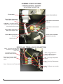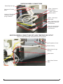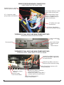
1
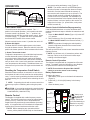
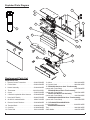
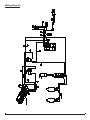
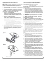
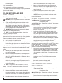
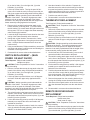
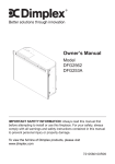
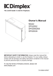
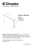
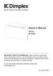
Service Manual
Model Number:
DF2426GB
DF2426SS
DF2550
DF2562
UL Part Number
6905050100 to 500
IMPORTANT SAFETY INFORMATION: Always read this manual first before attempting to service this
fireplace. For your safety, always comply with all warnings and safety instructions contained in this
manual to prevent personal injury or property damage.
Dimplex North America Limited
1367 Industrial Road Cambridge ON Canada N1R 7G8
1-888-346-7539 www.dimplex.com
In keeping with our policy of continuous product development, we reserve the right to make changes without notice.
© 2011 Dimplex North America Limited
REV
PCN
DATE
00
-
22-JUL-11
7400250000R00
TABLE OF CONTENTS
OPERATION. . . . . . . . . . . . . . . . . . . . . . . . . . . . . . . . . . . . . . . . . . . . . . . . . . . . . . . . . 3
PREPARATION FOR SERVICE. . . . . . . . . . . . . . . . . . . . . . . . . . . . . . . . . . . . . . . . . . 7
LIGHT HARNESS REPLACEMENT. . . . . . . . . . . . . . . . . . . . . . . . . . . . . . . . . . . . . . . 7
FLAME MOTOR/FLAME ROD REPLACEMENT. . . . . . . . . . . . . . . . . . . . . . . . . . . . . 8
HEATER ASSEMBLY REPLACEMENT. . . . . . . . . . . . . . . . . . . . . . . . . . . . . . . . . . . . 8
HIGH TEMPERATURE CUTOUT REPLACEMENT. . . . . . . . . . . . . . . . . . . . . . . . . . . 8
SWITCH REPLACEMENT – (MAIN POWER OR HEAT ON/OFF) . . . . . . . . . . . . . . 9
THERMOSTAT REPLACEMENT. . . . . . . . . . . . . . . . . . . . . . . . . . . . . . . . . . . . . . . . . 9
REMOTE RECEIVER BOARD REPLACEMENT. . . . . . . . . . . . . . . . . . . . . . . . . . . . . 9
POWER CORD REPLACEMENT. . . . . . . . . . . . . . . . . . . . . . . . . . . . . . . . . . . . . . . . 10
ASSEMBLY PART PICTURES. . . . . . . . . . . . . . . . . . . . . . . . . . . . . . . . . . . . . . . . . . . 11
LOWER ELECTRICAL HOUSING . . . . . . . . . . . . . . . . . . . . . . . . . . . . . . . . . . . . . . . . . . . . . . . . . . .
UPPER PANEL TERMINAL BLOCK CONNECTIONS . . . . . . . . . . . . . . . . . . . . . . . . . . . . . . . . . . .
HEATER ASSEMBLY CONNECTIONS . . . . . . . . . . . . . . . . . . . . . . . . . . . . . . . . . . . . . . . . . . . . . . .
HEATER ASSEMBLY CONNECTIONS WITH HIGH TEMPERATURE CUTOUT. . . . . . . . . . . . . . .
REMOTE RECEIVER BOARD CONNECTIONS . . . . . . . . . . . . . . . . . . . . . . . . . . . . . . . . . . . . . . . .
THERMOSTAT DIAL; HEAT; AND MAIN POWER SWITCHES. . . . . . . . . . . . . . . . . . . . . . . . . . . . .
THERMOSTAT DIAL; HEAT; AND MAIN POWER SWITCHES. . . . . . . . . . . . . . . . . . . . . . . . . . . . .
11
11
12
12
13
13
13
Always use a qualified technician or service agency to repair this fireplace.
! NOTE: Procedures and techniques that are considered important enough to emphasize.
CAUTION: Procedures and techniques which, if not carefully followed, will result in damage to the
equipment.
Warning: Procedures and techniques which, if not carefully followed, will expose the user to the
risk of fire, serious injury, or death.
2
www.dimplex.com
OPERATION
Figure 1
C
B
A
A. Main ON/OFF Switch
The switch has two ON positions marked. The “ -- “
position is for manual operation. In this position the builtin remote control is by-passed. The “ = “ position is for
operating the unit with the provided remote control. When
in remote control (“ = “) position the unit is operated with
the ON and OFF buttons of the remote control.
When the switch is in the center “o” position the unit is off.
B. Heater ON Switch
The Heat ON/OFF Switch supplies power to the heater
fan and the heater element. When the switch is in the ON
position the heater operates if the thermostat calls for heat.
C. Heater Thermostat Control
To adjust the temperature to your individual requirements,
turn the thermostat control clockwise all the way to
turn on the heater. When the room reaches the desired
temperature, turn the thermostat knob counter-clockwise
until you hear a click. Leave in this position to maintain the
room temperature at this setting. For additional heat, turn
clockwise until you hear the click again and the heater will
turn on.
Resetting the Temperature Cutoff Switch
Should the heater overheat, an automatic cut out will turn
the fireplace off and it will not come back on without being
reset. It can be reset by switching the Main On/Off Switch
to Off and waiting five (5) minutes before switching the unit
back on.
! NOTE: If operating the unit with a remote control, the
remote may require re-initializing after turning the power
off.
CAUTION: If you need to continuously reset the heater,
disconnect power and call Dimplex customer service at
1-888-DIMPLEX (1-888-346-7539).
Remote Control
The fireplace is supplied with a radio frequency remote
control. This remote control has a range of approximately
50 feet (15.25 m), it does not have to be pointed at the
fireplace and can pass through most obstacles (including
walls). It is supplied with one of hundreds of independent
frequencies to prevent interference with other units.
! NOTE: Before attempting any operation with the
remote, pull the plastic insulator strip out from between
the remote casing and battery cover (Figure 2).
! NOTE: The remote control is an EEPROM system;
therefore if power is interrupted for whatever reason,
the built-in receiver board will hold the memory of
the remote’s radio frequency for up to 24 hours. The
remote should continue to operate the fireplace as
normal once unit is re-powered. Re-initialization of
the remote transmitter to the fireplace should only be
required if there is a loss of power to the receiver for
longer than 24 hours. (i.e. power failure, main power
switch is turned off).
Remote Control Initialization/Reprogramming
If the hand held transmitter or receiver board has been
replaced, follow these steps to initialize the transmitter and
receiver:
1. Place the Main ON/OFF Switch (Figure 1A) in the OFF
(“O”) position.
2. Wait a minimum of five (5) seconds and then place
the Main ON/OFF Switch in the Remote Control (“=”)
position.
3. Within 10 seconds of changing the switch position,
press the ON button located on the remote control
transmitter (Figure 2).
This will synchronize the remote control transmitter and the
fireplace receiver.
! NOTE: You will have only 10 seconds to perform this
last step. Failure to do so will result in these steps
needing to be followed again.
Remote Control Operation
The fireplace is supplied with an integrated on/off remote
control. To operate, push the ON button to turn fireplace
on, push the OFF button to turn the fireplace off.
! Note: Ensure that the fireplace Main ON/OFF
switch is set to the remote control setting.
Battery Replacement
To replace the battery:
1. Slide battery cover open on the hand held transmitter
(Figure 2).
2. Install one (1) 12-Volt (A23) battery in the battery
holder.
3. Close the battery cover
Figure 2
On
Button
Off Button
Plastic
Strip
Battery must
be recycled or
disposed of
properly. Check with
your Local Authority or
Retailer for recycling
advice in your area.
Battery
Cover
3
Light Bulb Replacement
Glass Cleaning
Allow at least five (5) minutes for light bulbs to cool before
touching bulbs to avoid accidental burning of skin.
Light bulbs need to be replaced when you notice a dark
section of the flame or when the clarity and detail of the log
ember bed exterior disappears. There are two (2) bulbs
under the log set, which generate the flames and embers.
The front glass is cleaned in the factory during the
assembly operation. During shipment, installation,
handling, etc., the front glass may collect dust particles,
these can be removed by dusting lightly with a clean dry
cloth.
To remove fingerprints or other marks, the glass can be
cleaned with a damp cloth. The glass should be completely
dried with a lint free cloth to prevent water spots. To
prevent scratching, do not use abrasive cleaners or spray
liquids on the glass surface.
Light Bulb Requirements
Quantity of two (2) clear chandelier or candelabra bulbs
with an E-12 (small) socket base, 60 Watt rating. Example:
GE 60BC or Philips 60 CTC.
Do not exceed 60 Watts per bulb.
Helpful Hints
It is a good idea to replace both light bulbs at one time
if they are close to the end of their rated life. Group
replacement will reduce the number of times you need to
open the unit to replace light bulbs. Care must be taken
when removing the log set.
Fireplace Surface Cleaning
To remove fingerprints or other marks, the exterior finish
can be cleaned with a damp cloth with a mild detergent.
The surface should be completely dried with a lint free cloth
to prevent water spots.
Figure 3
To Access The Lower Light Bulb Area: (Figure 2)
1. Remove front glass assembly.
2. Pull the back edge of the plastic ember bed forward
until the rear tab releases from the ledge located at the
bottom of the mirror.
Flicker
! IMPORTANT: Only handle the log set by the ember bed.
! NOTE: Log set fits tightly into firebox, some force may
be necessary to remove.
3.
4.
5.
6.
7.
8.
Set log set in front of fireplace.
Disconnect flicker from motor (see Figure 2).
Unscrew bulbs counter clockwise.
Insert new bulbs.
Reconnect flicker to motor.
Replace the log set by inserting the front edge of the
log set and push down on the rear edge of the ember
bed until it snaps into place (Figure 3).
! NOTE: Ensure the log set is installed tightly under the
back ledge to prevent light leakage.
9. Replace glass assembly.
Figure 4
Mirror
Ember Bed
Assembly
Back Ledge
Rear Tab
Front Edge
Side Section
4
www.dimplex.com
Exploded Parts Diagram
9
3
5
11
14
13
1
16
16
4
7
8
15
10
12
6
2
Replacement Parts List
Replacement Part:
1. Remote Control Transmitter . . . . . . . . . . 3000370500RP
2. Flicker Motor. . . . . . . . . . . . . . . . . . . . . . 2000210200RP
3. Heater Assembly . .
. . . . . . . . . . . . . . . 2200491200RP
4. Thermostat . . . . . . . . . . . . . . . . . . . . 2300150100RP*
5. Cutout. . . . . . . . . . . . . . . . . . . . . . . . . 2300270100RP
6. 2 Socket Lampholder Wire Harness. . . . 2500400500RP
7. Heat On/Off Switch . . . . . . . . . . . . . . . 2800070700RP
8. On-Off-On marked Switch. . . . . . . . . . . . 2800071100RP
13. Mirror . . . . . . . . . . . . . . . . . . . . . . . . . 5901410200RP
14. Control Knob . . . . . . . . . . . . . . . . . . . . . 8801080100RP
15.DF2426SS Stainless Steel Trim Assembly
(comes with Front Glass). . . . . . . . . . . . . . . 1020230280RP
DF2426GB Gloss Black Trim Assembly
(comes with Front Glass). . . . . . . . . . . . . . . 1020230104RP
DF2550 Flat Black Trim Assembly
(comes with Front Glass). . . . . . . . . . . . . . . 1020230359RP
6905050400/6905050500 Silver Trim Assembly
(comes with Front Glass). . . . . . . . . . . . . . . 1020230478RP
9. Remote Control Receiver .
. . . . . . . . . 3000380200RP 16. DF2426SS/DF2426GB/DF2550
Log Set Assembly. . . . . . . . . . . . . . . . . . . . . 0439970100RP
10. Terminal Block . . . . . . . . . . . . . . . . . . 4000080100RP
6905050400/6905050500
11. Cord Set . . . . . . . . . . . . . . . . . . . . . . . 4100040300RP Tray. . . . . . . . . . . . . . . . . . . . . . . . . . . . . . . . 0440400100RP
12. Flicker Rod . . . . . . . . . . . . . . . . . . . . . . . 5901110100RP
Glass Media. . . . . . . . . . . . . . . . . . . . . . . . . 1400070100RP
5
Wiring Diagram
6
www.dimplex.com
PREPARATION FOR SERVICE
CAUTION: If unit was operating prior to servicing allow
at least 10 minutes for lights, heating elements and top
panel to cool off to avoid accidental burning of skin.
1. Remove the firebox out of the cabinet or wall frame that
surrounds the unit.
2. Disconnect power before attempting any maintenance.
! NOTE: This unit may have been installed to a power
source in one of 2 ways: (SEE FIGURE 5 & 6).
• Option #1 – Plug into an outlet.
A power cord with plug, inserted into an outlet near
or behind the fireplace, unplug the fireplace from the
outlet.
• Option #2 – Hardwire connection.
Power supplied from electrical wire coming from a
dedicated, properly fused circuit with 120 Volt, 15 Amp
rating directly from the main electrical panel, turn the
breaker off at the electrical panel.
• It is recommended during original installation,
there should be an allowance of up to 8 feet of
service cable for connecting power supply to the
junction box on fireplace.
3. Remove the front glass assembly by lifting the front
glass assembly off of the 4 mounts located on the outer
casing of the fireplace (2) on the left and (2) on the
right. Carefully place the glass assembly aside in a
safe location.
Figure 5
Figure 6
LIGHT HARNESS REPLACEMENT
Tools required: Phillips head screw driver.
Small cutter or snips
CAUTION: Follow “Preparation for Service” instructions
before proceeding.
1. Slightly wedge your fingers between the back mirror and the log-set/ember-bed on either the right or
left side. Pull the back edge of the plastic ember bed
forward until the rear tab/ledge clears past the bottom
of the mirror and pull the log set forward and out of the
unit. (Figure 4).
! IMPORTANT: Only handle the log-set by the plastic
ember-bed, not the logs themselves.
! NOTE: Log-set fits tightly into firebox. Some force
may be necessary to remove.
! NOTE: If your model has the media tray with the
decorative glass pieces as an ember bed, remove the glass
pieces then remove the plastic media tray following the
same method as the log set removal instructions.
2. Set log-set aside in a safe location.
3. Disconnect the flicker rod from the motor by pulling and
twisting the rubber gasket/connector away from the
motor. This is the gasket which joins the rod and the
motor together. Once separated, pull the flicker rod out
from the bracket and bushing from opposite side, and
remove it from the firebox.
! NOTE: Be careful not to bend the rod. Doing so may
damage the rod. Ensure the rod is straight after re-installation so that it doesn’t affect the operation of the flame
effect.
4. Carefully turn the firebox upside down so that the bottom panel is facing up.
5. Remove the 9 screws that hold the bottom panel in
place, (2) on the back, (2) on the left, (2) on the right
and (3) on the bottom along the front edge.
6. Remove the light bulbs by turning counter clockwise.
7. Remove the rings sockets that hold the sockets to the
side panel by turning/unscrewing the rings counter
clockwise. Push the sockets out of the panel.
8. Snip the wire ties that are holding the wires to the casing.
9. Remove the light harness wire ends out of the terminal
block by removing the small Philips head screw in the 2
respective terminals.
10. Insert the wire ends from the new light harness into
the terminal block following the same orientation of the
original harness.
11. Tighten terminal screws to secure wires in place.
12. Insert the new sockets into the opening on the socket
panel on the left and right. Place the socket ring onto
the socket and tighten to secure the socket into place.
13. Tuck the light harness wires around the light panel/casing so that they will not be pinched when re-attaching
7
the bottom panel.
14. Insert new bulbs.
15. Re-assemble the firebox in reverse order.
! NOTE: Ensure the rear tab/ledge on the log-set/emberbed is installed tightly under the bottom of the mirror to
prevent light leakage.
FLAME MOTOR/FLAME ROD
REPLACEMENT
Tools Required: Phillips head screw driver. (Regular
length and stubby length).
CAUTION: Follow “Preparation for Service” instructions
before proceeding.
1. Slightly wedge your fingers between the back mirror
and the log-set/ember-bed on either the right or left
side. Pull the back edge of the plastic ember bed forward until the rear tab/ledge clears past the bottom of
the mirror and pull the log set forward and out.
! IMPORTANT: Only handle the log-set by the plastic
ember-bed, not the logs themselves.
! NOTE: Log-set fits tightly into firebox. Some force
may be necessary to remove.
! NOTE: If your model has the media tray with the
decorative glass pieces as an ember bed, remove the glass
pieces then remove the plastic media tray following the
same method as the log set removal instructions.
2. Set log set aside in a safe location.
3. Disconnect flicker rod from the motor by slightly bending the flicker rod and pulling the rubber gasket off the
motor shaft. (Figure 3).
! NOTE: Be careful not to bend the rod. Doing so may
damage the rod. Ensure the rod is straight after re-installation so that it doesn’t affect the operation of the flame
effect.
4. Carefully turn the firebox upside down so that the bottom panel is facing up.
5. Remove the 9 screws that attach the bottom panel to
the side panels, (2) on the back side, (2) on the left
side, (2) on the right side and (3) on the bottom along
the front edge.
6. Remove the 3 flicker motor wire ends out of the terminal block by removing the small Philips head screw in
the 3 respective terminals. Take note of their location
on the terminal block.
! NOTE: A capacitor is also connected in 2 of the 3
terminals that hold the flame motor wires on the terminal
block. Take note of the terminal locations and the wire
configuration.
7. Using a stubby Philips screwdriver (short handle &
shaft), remove the 2 screws holding the flicker motor to
the mounting brackets. (One screw on either side) and
remove the flicker motor out of the housing. Note the
correct orientation on the brackets.
8. Place the new motor into the housing and attach the
motor to the brackets using the 2 Philips screws.
9. Insert the 3 wire ends from the new flicker motor as
well as the 2 wires from the original capacitor into the
terminal block following the orientation of the original
motor & capacitor.
10. Tighten terminal screws to secure wires in place.
11. Re-assemble the firebox in reverse order.
! NOTE: Ensure the rear tab/ledge on the log-set/ember-bed is installed tightly under the bottom of the mirror to
prevent light leakage.
HEATER ASSEMBLY REPLACEMENT
Tools Required: Philips head screwdriver
Needle nose pliers
CAUTION: Follow “Preparation for Service” instructions
before proceeding.
1. Remove 9 screws that secure the top panel to the side
panels of the firebox using a Philips head screwdriver,
(2) on the left side; (2) on the right side; (3) on the
backside; (2) on the top.
2. Lift the top off the firebox. Turning the panel 45 degrees, rest it inside the cavity at the top to provide you
with some support and leverage while following Steps
4 & 5.
3. Noting their original location, disconnect the wires attached to the end of the heater assembly on the blower
motor and element. Pliers may be required for grip
when disconnecting the wire/spade connectors.
! NOTE: Some of the wires may have a “piggy-back”
connector that allows a second wire to connect to the same
prong as the first wire. (Two wires will connect on one
prong). Keep the “piggy-back” connection together when
pulling the wires off the heater assembly.
4. Remove the 2 mounting brackets that attach the heater
assembly to the top panel. It’s held by 4 Philips head
screws located on the top panel going into the bracket
- (2) screws on the left bracket; (2) screws on the right
bracket.
5. Detach the mounting brackets from the heater assembly by removing the 2 Philips screws from each
bracket.
6. Attach the brackets to the new heater assembly and
then attach brackets to the top panel.
7. Re-assemble in reverse order as above.
HIGH TEMPERATURE CUTOUT
REPLACEMENT
Tools Required: Philips head screwdriver - (regular and
small diameter head)
Needle nose pliers
CAUTION: Follow “Preparation for Service” instructions
before proceeding.
1. Remove 9 screws that secure the top panel to the side
panels of the firebox using a Philips head screwdriver,
8
www.dimplex.com
(2) on the left side; (2) on the right side; (3) on the
backside; (2) on the top.
2. Lift the top off the firebox. Turning the panel 45 degrees, rest it inside the cavity in the top to provide you
with some support and leverage while following Step 4.
CAUTION: Wedge something small underneath the
backside of the firebox. The bottom legs/spacers underneath the unit do not span the full depth of the firebox
therefore it can easily tip backwards with the weight of the
heater assembly resting against the back panel.
3. Remove the 2 mounting brackets that attach to the
heater assembly to the top panel. (2) screws attach
the left bracket; (2) screws attach the right bracket from
the top panel. Be sure to support the heater assembly
when removing the brackets.
4. Locate the High Temperature Cutout found on the outer
casing of the heater assembly at the elements.
5. Noting their original location, disconnect the 2 wires
from the High Temperature cutout going to the terminal
block. A Philips head screw attaches the wires into
each terminal.
6. Using a small diameter, Philips screwdriver, remove the
old cutout and replace it with the new one following the
orientation of the original wires.
7. Re-assemble in reverse order as described above.
SWITCH REPLACEMENT – (MAIN
POWER OR HEAT ON/OFF)
Tools Required: Philips head screwdriver
Needle nose pliers
CAUTION: Follow “Preparation for Service” instructions
before proceeding.
1. Remove 9 screws that secure the top panel to the side
panels of the firebox using a Philips head screwdriver,
(2) on the left side; (2) on the right side; (3) on the
backside; (2) on the top.
2. Lift the top panel up off the firebox, turn it 45 degrees
and rest it inside the upper cavity against the back
panel.
CAUTION: Wedge something small underneath the
backside of the firebox. The bottom legs/spacers underneath the unit do not span the full depth of the firebox
therefore it can easily tip backwards with the weight of the
heater assembly resting against the back panel.
3. The switch housing panel spans across the front of the
fireplace, near the top. Remove the 6 screws from the
side panels that hold this front panel in place, (3) on the
left and (3) on the right side.
4. Lift the switch-housing panel up and flip it 180 degrees
towards you to expose the wires connected to the
backside of the switch.
5. Take note of the original location of each wire connected to the switch that needs replacing, (either the Main
ON/OFF or the Heat ON/OFF switch).
6. Note the orientation of the switches. Depress the
tabs that secure the switch to the housing from behind
the panel and push the switch out to the front. Using
needle nosed pliers will give you a better grip and fit to
depress both these tabs at the same time.
7. Push the new switch in place.
8. Re-assemble in reverse order as described above.
THERMOSTAT REPLACEMENT
Tools Required: Philips head screwdriver
CAUTION: Follow “Preparation for Service” instructions
before proceeding.
1. Remove 9 screws that secure the top panel to the side
panels of the firebox using a Philips head screwdriver,
(2) on the left side; (2) on the right side; (3) on the
backside; (2) on the top.
2. Lift the top panel up off the firebox, turn it 45 degrees
and rest it inside the upper cavity against the back
panel.
CAUTION: Wedge something small underneath the
backside of the firebox. The bottom legs/spacers underneath the unit do not span the full depth of the firebox
therefore it can easily tip backwards with the weight of the
heater assembly resting against the back panel.
3. On the front face of the switch housing, remove the 2
screws that hold the thermostat to the panel.
4. The switch housing panel spans across the entire top
on the front of the fireplace. Remove the 6 screws from
the side panels that hold this front panel in place, (3) on
the left and (3) on the right side.
5. Lift the switch-housing panel up and flip it 180 degrees
towards you to expose the wires connected to the
backside of the thermostat.
6. Push the thermostat dial into the switch housing and remove dial off the control shaft by pulling forward away
from the thermostat. (Take note that the dial will only go
back on the shaft one way when replacing).
7. Remove thermostat from the mounting bracket by removing the 2 Philips screws located on the bracket.
8. Take note of the original location of each wire connected to the thermostat and place onto the new thermostat.
9. Re-assemble in reverse order as described above.
REMOTE RECEIVER BOARD
REPLACEMENT
Tools Required: Philips head screwdriver
Needle nose pliers
Small cutter or snips
CAUTION: Follow “Preparation for Service” instructions
before proceeding.
1. Remove 9 screws that secure the top panel to the side
panels of the firebox using a Philips head screwdriver,
(2) on the left side; (2) on the right side; (3) on the
9
backside; (2) on the top.
2. Lift the top panel up off the firebox, turn it 45 degrees
and rest it inside the upper cavity against the back
panel.
CAUTION: Wedge something small underneath the
backside of the firebox. The bottom legs/spacers underneath the unit do not go span the full depth of the firebox
therefore it can easily tip backwards with the weight of the
heater assembly resting against the back panel.
3. The switch housing panel spans across the entire top
on the front of the fireplace. Remove the 6 screws from
the side panels that hold this front panel in place, (3) on
the left and (3) on the right side.
4. Lift the switch-housing panel up and also carefully rest
inside the upper cavity.
5. Take note of the original location of each wire connected to the board. Remove each wire and connect onto
the same location on the new receiver board.
! NOTE: Using needle nosed pliers will give you a better grip to grasp the connectors at the end of the wires at
the board. Carefully wiggle the connector until it slides off
the spade on the board.
6. Remove the old board off the plastic mounts, cut or
pinch the plastic mounting tabs with snips or needle
nose pliers. Pull the old board off. Push the old
mounts out towards the back. Insert and push the
new mounts in from the back panel. Line up the holes
on the corners of the new remote receiver board and
press the new board onto the mounts. Make sure the
board is secure.
7. Re-assemble in reverse order as described above.
POWER CORD REPLACEMENT
Tools required: Phillips head screw driver.
Needle nosed pliers.
CAUTION: Follow “Preparation for Service” instructions
before proceeding. Steps 1 & 2 only.
1. Remove power cord junction box cover by removing
the 2 Philips screws mounted to the back panel of the
fireplace.
2. Unscrew the 2 wire connectors that join the power cord
at the bottom to the wire leads coming down from the
top.
3. With a pair of needle nose pliers, open the strain relief
bushing that holds the power cord in place on the junction box cover and remove the cord.
4. Feed the new power cord through the junction box and
squeeze the new strain relief in place on the cord and
junction box. Re-connect wires. –(Wide blade on the
plug is the neutral side of the power cord).
5. Re-assemble in the reverse order as above.
10
www.dimplex.com
ASSEMBLY PART PICTURES
LOWER ELECTRICAL HOUSING
VIEW FROM THE BOTTOM
Flicker Motor
Lower Terminal Block
Flicker Motor Connection White (with capacitor wire)
Capacitor - Connects to the terminals with the borwn and white
wires from the flame motor
Flicker Motor Connection White (with capacitor wire)
Flicker Motor Connection
- Black Single
Light Harness Connection
- Neutral
Light Harness Connection
- Live
Power Cord or Hardwire
Internal Connection
Light Socket
UPPER PANEL TERMINAL BLOCK CONNECTIONS
White - connects to a piggy back
connection on JP3 prong on
circuit board
Long white connects to
lower electrical housing
Red - Connects to the Inside/
middle prong on heat on/off
switch
White - “Piggy-backed” to
white jumper from bottom
prong on the element
Red - From High Temperature
Cutout
Grey - From High Temperature
Cutout
Grey - Connects to the Thermostat
Grey - To Blower motor outside
prong.
11
HEATER ASSEMBLY CONNECTIONS
Blower/Squirrel Cage
White - Connects to
Terminal Block
White - Jumper to
Blower Motor
Connects to Terminal
Block
Jumper to “Piggy Back”
connection on lower
prong of element
Yellow - Connects to
Thermostat
Grey - Connects to High
Temperature Cutout on
Terminal Block
Red - from the high temperature cutout to the
terminal block.
HEATER ASSEMBLY CONNECTIONS WITH HIGH TEMPERATURE CUTOUT
View of heater assembly removed from the top panel
High Temperature Cutout
Element Housing
Blower/Squirrel Cage
Housing
Blower Motor
Upper Panel Terminal
Block
12
www.dimplex.com
REMOTE RECEIVER BOARD CONNECTIONS
VIEW FROM THE TOP RIGHT SIDE
Stand-Off Clips (4) - Attaching
receiver board to housing
Switch Output (Black) to outside
prong of Main On/Off Switch
JP1 - Connects to inside
prong of Main On/Off Switch
Switch Output (Black “Piggy
Back”) to “Piggy Back” Connection on Outside Prong on
Heater On/Off Switch
JP3 (White) from upper
terminal block
JP3 (White “Piggy Back”)
from lower electrical housing
THERMOSTAT DIAL; HEAT; AND MAIN POWER SWITCHES
EXTERIOR VIEW OF SWITCH PANEL
Heater On/Off Switch
O - Off
-- On
Thermostat Dial
Main On/Off Switch
= Remote Control
O Off
-- Manual Control
THERMOSTAT DIAL; HEAT; AND MAIN POWER SWITCHES
INTERIOR VIEW – BACK SIDE OF SWITCH PANEL
Outside Prong (Black) connects to
Switch Output (Black “Piggy back”)
on Receiver Board
Middle Prong (Black) connects to
Black from lower electrical housing
Inside Prong (Red) connects to JP1
on Receiver Board
Yellow from Heating
Element
Grey from Upper
Panel Terminal Block
• Outside Prong (Black) connects to
Lower Electrical Housing
• Outside Prong (Black - “Piggy Back”)
to Switch Output on Reciever Board
Inside Prong (Red) connects
to Upper Terminal Block
13