1
2012 Modular Remote Power (MRP)
Copyright 2012 Bay Technical Associates, Inc 12/1/2012 Table of Contents COMPLIANCE STANDARD .............................................................................................................................................................. 5 CONNECTION DESCRIPTION ........................................................................................................................................................... 6 EIA‐232 SERIAL CONNECTION ..................................................................................................................................................................... 6 10/100 BASE‐T NETWORK PORT CONNECTION .............................................................................................................................................. 6 MODEM COMMUNICATIONS ........................................................................................................................................................................ 6 INSTALLATION ............................................................................................................................................................................... 7 UNPACKING .............................................................................................................................................................................................. 7 PREPARING THE INSTALLATION SITE ............................................................................................................................................................... 7 POWER .................................................................................................................................................................................................... 7 CIRCUIT BREAKER ....................................................................................................................................................................................... 9 UNIT PROCESSORS ..................................................................................................................................................................................... 9 CABLING ...................................................................................................................................................................................... 10 RJ‐45 CABLE ........................................................................................................................................................................................... 10 ADAPTERS .............................................................................................................................................................................................. 11 RACK MOUNT HARDWARE .......................................................................................................................................................... 12 SERIAL SETUP .............................................................................................................................................................................. 13 OPERATION IMPORTANT: ........................................................................................................................................................................... 13 OUTLET STATUS ....................................................................................................................................................................................... 13 QUICK START: MRP SERIES .......................................................................................................................................................... 14 OUTLET CONTROL CONFIGURATION: ............................................................................................................................................................ 14 ETHERNET CONFIGURATION: ...................................................................................................................................................................... 15 NETWORK MENU ........................................................................................................................................................................ 21 OUTLET CONTROLLER STATUS SCREEN ......................................................................................................................................... 22 OUTLET HELP OPTIONS ................................................................................................................................................................ 23 RECEPTACLE CONTROLS ............................................................................................................................................................................. 23 ON, OFF, REBOOT, LOCK, AND UNLOCK ....................................................................................................................................................... 23 STATUS ................................................................................................................................................................................................ 24 OUTLET CONTROL CONFIGURATION MENU ................................................................................................................................................... 25 Manage Users ................................................................................................................................................................................ 25 Change Outlet Name ...................................................................................................................................................................... 28 Enable/Disable Confirmation ......................................................................................................................................................... 28 Enable/Disable Status Menu .......................................................................................................................................................... 29 Change Unit ID................................................................................................................................................................................ 29 Change Alarm Threshold ................................................................................................................................................................ 29 Change Display Orientation ............................................................................................................................................................ 30 DISPLAY CURRENT ELECTRICAL CHARACTERISTICS: .......................................................................................................................................... 30 LOGGING OUT ......................................................................................................................................................................................... 31 CURRENT USER PASSWORD: ....................................................................................................................................................................... 31 IDENTIFY CURRENT USER ........................................................................................................................................................................... 31 UNIT IDENTIFICATION ................................................................................................................................................................................ 31 Page
OVERALL SYSTEM STATUS .......................................................................................................................................................................... 32 NETWORK STATUS .................................................................................................................................................................................... 32 LOGGED USERS ........................................................................................................................................................................................ 32 MEMORY USAGE ..................................................................................................................................................................................... 32 CURRENT ROUTING CACHE ........................................................................................................................................................................ 33 ROUTE SETUP .......................................................................................................................................................................................... 33 2 STATUS MENU ............................................................................................................................................................................. 32 PROCESSES ............................................................................................................................................................................................. 33 UNITINFO DATABASE ................................................................................................................................................................................ 33 NETWORK CONFIGURATION MENU: ............................................................................................................................................ 34 UNIT RESET ................................................................................................................................................................................. 61 3 LOGOUT ...................................................................................................................................................................................... 61 Page
STATUS .................................................................................................................................................................................................. 34 SERIAL PORT CONFIGURATION .................................................................................................................................................................... 35 Handshaking ................................................................................................................................................................................... 35 Baud Rate ....................................................................................................................................................................................... 36 Word Size ........................................................................................................................................................................................ 36 Stop Bits .......................................................................................................................................................................................... 37 Parity .............................................................................................................................................................................................. 37 RTS/DTR Line Driver Inactivity State ............................................................................................................................................... 37 SERIAL PORT DEVICE NAME ....................................................................................................................................................................... 38 ATTENTION CHARACTER ............................................................................................................................................................................ 38 DISCONNECT TIMEGUARD .......................................................................................................................................................................... 38 CONNECT PORT ID ECHO ........................................................................................................................................................................... 38 LOGIN SETUP MENU ................................................................................................................................................................................. 39 Access Control ................................................................................................................................................................................ 39 Manage Users ................................................................................................................................................................................ 39 Radius Configuration ...................................................................................................................................................................... 41 TACACS Configuration .................................................................................................................................................................... 42 NETWORK PORT CONFIGURATION ............................................................................................................................................................... 44 IP Address ....................................................................................................................................................................................... 44 Subnet Mask ................................................................................................................................................................................... 44 Gateway Address ............................................................................................................................................................................ 45 Inactivity Timeout ........................................................................................................................................................................... 45 Carriage Return Translation ........................................................................................................................................................... 45 Break Length ................................................................................................................................................................................... 45 DHCP Enable/Disable ...................................................................................................................................................................... 45 Telnet Enable/Disable ..................................................................................................................................................................... 45 SSH Enable/Disable ......................................................................................................................................................................... 46 SSH Host Key Generation ................................................................................................................................................................ 46 IP Filter Configuration ..................................................................................................................................................................... 46 SNMP Configuration ....................................................................................................................................................................... 47 Web Server Configuration .............................................................................................................................................................. 48 MODULE NAME ....................................................................................................................................................................................... 49 RPC MANAGEMENT ................................................................................................................................................................................. 49 Temperature Alarm Threshold ....................................................................................................................................................... 49 Under Voltage Alarm Threshold ..................................................................................................................................................... 50 Over Voltage Alarm Threshold ....................................................................................................................................................... 50 Low Current Alarm Threshold ......................................................................................................................................................... 50 Environmental Sensors ................................................................................................................................................................... 50 Outlet Groups ................................................................................................................................................................................. 51 Temperature Units (degrees C/F) ................................................................................................................................................... 53 RPC Cascade Mode ......................................................................................................................................................................... 53 Power Factor Threshold Menu ....................................................................................................................................................... 55 FIRMWARE/CONFIG DOWNLOAD ................................................................................................................................................................ 58 Enable Firmware Upgrade .............................................................................................................................................................. 58 Enable SSL Cert Upload ................................................................................................................................................................... 58 Enable Configuration File Upload ................................................................................................................................................... 59 Restore Configuration Defaults ...................................................................................................................................................... 59 Get Current Configuration File ........................................................................................................................................................ 60 Display Configuration Error Log ..................................................................................................................................................... 60 Enable Rel Ctl. Firmware Upgrade .................................................................................................................................................. 60 BAYTECH PRODUCT WARRANTY .................................................................................................................................................. 62 EXCEPTIONS ............................................................................................................................................................................................ 62 BAYTECH EXTENDED WARRANTY ................................................................................................................................................................ 62 TECHNICAL SUPPORT ................................................................................................................................................................................ 63 REPAIR POLICY......................................................................................................................................................................................... 63 RETURN AUTHORIZATION PROCESS: ............................................................................................................................................................. 64 APPENDIX: TACACS CONNECTION SCENERIOS .............................................................................................................................. 65 APPENDIX: LCD DISPLAY DESCRIPTION ......................................................................................................................................... 66 APPENDIX: LED DISPLAY DESCRIPTION ......................................................................................................................................... 67 APPENDIX: TROUBLESHOOTING................................................................................................................................................... 67 Page
4 Serial 1: Port Pin out Table ____________________________________________________________________________________ 10 Serial 2: RJ08X007 Pin out ____________________________________________________________________________________ 11 Serial 3: RJ45 Receptacle & Plug _______________________________________________________________________________ 11 Serial 4: 9FRJ45PC Cisco Adapter Pin Out ________________________________________________________________________ 11 Serial 5: 9FRJ45PC‐1 Adapter Pin out ____________________________________________________________________________ 11 Figure 1: Outlet Status _______________________________________________________________________________________ 16 Figure 2: Outlet Help ________________________________________________________________________________________ 16 Figure 3: Outlet Password ____________________________________________________________________________________ 17 Figure 4: Outlet Configuration _________________________________________________________________________________ 17 Figure 5: Outlet Manage User _________________________________________________________________________________ 17 Figure 6: Outlet Assignment ___________________________________________________________________________________ 18 Figure 7: Network Menu ______________________________________________________________________________________ 19 Figure 8: Network Configuration _______________________________________________________________________________ 19 Figure 9: Network Login Setup _________________________________________________________________________________ 19 Figure 10: Network Access Control _____________________________________________________________________________ 19 Figure 11: Network Login Prompt ______________________________________________________________________________ 19 Figure 12: Network Manage Users _____________________________________________________________________________ 20 Figure 13: Network Port Configuration __________________________________________________________________________ 20 Outlet 1: Outlet Control Help __________________________________________________________________________________ 23 Outlet 2: Outlet Configuration _________________________________________________________________________________ 25 Outlet 3: Outlet Manage Users ________________________________________________________________________________ 25 Status Menu 1: Network Status ________________________________________________________________________________ 32 Menu 1: Network Configuration _______________________________________________________________________________ 34 Menu 2: Serial Port Configuration ______________________________________________________________________________ 35 Menu 3: Network Login ______________________________________________________________________________________ 39 Menu 4: Network Manage User ________________________________________________________________________________ 39 Menu 5: Network Radius Configuration __________________________________________________________________________ 41 Menu 6: Network TACACS Configuration _________________________________________________________________________ 42 Menu 7: Network Port Configuration ____________________________________________________________________________ 44 Menu 8: Network IP Filter Configuration _________________________________________________________________________ 46 Menu 9: Network SNMP Configuration __________________________________________________________________________ 47 Menu 10: Web Server Configuration ____________________________________________________________________________ 48 Menu 11: Network RPC Management ___________________________________________________________________________ 49 Menu 12: Network RPC Cascade Mode __________________________________________________________________________ 53 Menu 13: Network Firmware/Config Download ___________________________________________________________________ 58 ABOUT THIS MRP OWNER’S MANUAL This document provides information required for installing and operating your Bay Tech equipment. It
should allow the user to connect to, power up, and access an applications menu where peripheral
equipment can be controlled. We recommend reading this manual carefully, while placing special
emphasis on correct cabling and configuration. If you have any problems with your installation, please
contact a BayTech Applications Engineer at 228-563-7334, or toll free from anywhere in the United
States using 1-800-523-2702 or contact us at our Web Site, www.baytech.net.
BayTech manufactures many remote site management power products and data switches. If you would
like information on any of these products, please contact BayTech Customer Service at the above
numbers or visit our web site.
Conventions used in this manual include:
CAUTION: This term is used to denote any condition that could possibly result in physical
harm to personnel or damage to equipment.
IMPORTANT: This term is used to denote conditions that could result in the loss of
communications or to highlight the proper functioning of equipment.
NOTE: This term is used to denote items of interest to the user.
<cr>: Carriage Return or ENTER
The information in this document is subject to change without notice. The statements, configurations,
technical data, and recommendations in this document are believed to be accurate and reliable, but are
presented without express or implied warranty. Users must take full responsibility for their applications
of any products specified in this document. The information in this document is proprietary to Bay
Technical Associates, Inc.
In the interest of improving internal design, operational function, and/or reliability, Bay Technical
Associates, Inc reserves the right to make changes to the products described in this document without
notice.
Bay Technical Associates, Inc does not assume any liability that may occur due to the use or application
of the product(s) or circuit layout(s) described herein.
COMPLIANCE STANDARD Page
5 BayTech units are in accordance with the general requirements of Standard for Information Technology
Equipment (ETL listed, conforms to ANSI/UL 60950-1 2nd Edition and CAN/CSA C22.2 No. 60950-00.
CE conforms to IEC 60950.) Equipment installations are to be in accordance with the Canadian
Electrical Code, Part I, CSA C22.1-02; General Requirements – Canadian Electrical, Part II, CSA
C22.2 No 0-M91; the National Electrical Code, NFPA 70-2005; and the National Electrical Safety
Code, NFPA, IEEE C2-2002.
MDP =Modular Distribution Power. This is the plain power strip. No metering, no communications or
environmental port.
MMP = Modular Metered Power. This unit measures RMS voltage, and current. Calculates power in
watts and power factor efficiency per circuit. Also measures these factors for each outlet and has
Environmental Sensor, RS232 and/or Direct IP ports. Control and Non-Controllable Outlets
MRP = Modular Remote Power. This unit measures RMS voltage, and current. Calculates power in
watts and power factor efficiency per circuit and has Environmental Sensor, RS232 and/or Direct IP
ports. Controllable Outlets
MSP = Modular Sensor Power. This unit measures Input and circuit RMS current. Unit may have
Environmental Sensor, RS232 and/or Direct IP ports. Non-Controllable Outlets
Model number description: MRP10.01.328.324BL-XX
MRP10 = base unit MRP10 group includes Dual Circuit Breaker (6ea); 01 = Controller Module; LCD
Display, No Networking, Outlet Control; 3 = Quantity; 28 = Receptacle Module; 3 = Quantity; 24BL =
Receptacle Module; XX = Power plug type
We welcome any comments you may have about our products, and we hope that you will continue to
look to BayTech for your remote management needs.
CONNECTION DESCRIPTION BayTech's Modular Series unit provides a Serial EIA232 interface that controls user access and outlet
controls to the power strip.
CAUTION: All power should be removed from the BayTech unit prior to removing or installing
cables and /or adapters.
EIA232 Serial Connection The RPC has an RJ-45 port which uses an 8-pin crossed modular cable to connect to a local EIA-232
device such as a computer terminal or external modem. Most serial computers do not have RJ-45
connections; therefore an adapter is provided with this unit to convert from a DE-9 connector to an RJ45 connector (Bay Tech Part No. 9FRJ45PC-4). An adapter to convert from a DB-25 connector to an
RJ-45 connector is also available from Bay Tech, upon request (Bay Tech Part No. 25FRJ45PC-4). The
8-pin crossed modular cable is configured to operate with these adapters.
NOTE: Custom cables are available to connect a device to this unit’s serial port. These custom
cables are one-way cables labeled with Baytech on one end and a device name on the other end.
10/100 BaseT Network Port Connection Using a straight 10/100 Base-T cable, connect the RJ-45 port labeled ETHERNET on the HOST module
to an RJ-45 port on the network hub. The LINK (link integrity) LED, located on the front panel of the
HOST, illuminates when a good connection is established between the HOST and the hub.
Page
A modem can be connected to the EIA-232 serial port by using a 25-pin to RJ45 adapter (Bay Tech Part
No. 25MRJ45MD-8). Several types of modem adapters are available from BayTech. Contact an
applications engineer for help in choosing the correct adapter.
6 Modem Communications INSTALLATION Unpacking Compare the unit and serial number of the equipment you received to the packing slip located on the
outside of the box. Inspect equipment carefully for damage that may have occurred in shipment. If there is
damage to the equipment or if materials are missing, contact BayTech Customer Support at 228-563-7334
or call toll free inside the United States at 800-523-2702. At a minimum, you should receive the
following:
1.
2.
3.
4.
5.
The MRP unit.
Paper insert referencing BayTech’s website a www.baytech.net/support/ftp_series.php.
1 ea. DE-9 (9 pin) PC com port adapter -- 9FRJ45PC (with Cisco Interface) or 9FRJ45PC-1.
1 ea. RJ-45 Roll over cable -- RJ08X007.
1 set of either Vertical or Horizontal Brackets -- M140C138, M140R114, M140R115
NOTE: Keep the shipping container and packing material in the event future shipment is required.
Preparing the Installation Site The installation area should be clean and free of extreme temperatures and humidity. Allow sufficient
space behind the MRP/MMP/MSP/MDP unit for cabling and receptacle connections. Access to installation
site should be restricted to authorized personnel. Installation of these units should be limited to ITE and
Telco server environments.
PRÉPARATION DE L'EMPLACEMENT D'INSTALLATION
Le secteur d'installation devrait être propre et exempt des températures et de l'humidité extrêmes.
Permettez le suffisamment d'espace derrière l'unité de MRP/MMP/MSP/MDP pour des raccordements de
câblage et de réceptacle. L'accès à l'emplacement d'installation devrait être limité au personnel autorisé.
L'installation de ces unités devrait être limitée à ITE et à environnements de serveur de Telco.
Power
7
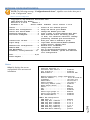
208V 3øY VAC Model: Internal 120/208 VAC, 3Ø, 50/60 Hz
(16, 20, 30, 32, 50 or 60 Amps Maximum Load).
400V 3øY VAC Model: Internal 230/400 VAC, 3Ø, 50/60 Hz
(16, 20, 30, 32, 50, or 60 Amps Maximum Load)
208V VAC Model: Internal 120/208 VAC 50/60 Hz
(10, 15, 16, 20, 30, 32, 50, or 60 Amps Maximum Load).
120V VAC Model: Internal 120 VAC 50/60 Hz
(15, 20, 30, 50, or 60 Amps Maximum Load).
Page
CAUTION: This unit is intended for indoor use only. Do not install near water or expose this unit
to moisture. To prevent heat buildup, do not coil the power cord when in use. Do not use extension
cords. Do not attempt to make any internal changes to the power source. Do not attempt to modify
any portion or component of an MRP/MMP/MSP/MDP Series Unit unless specifically directed to
by BayTech personnel. BayTech must perform any internal operations.
ATTENTION: Cette unité est prévue pour l'usage d'intérieur seulement. N'installez pas près de
l'eau ou n'exposez pas cette unité à l'humidité. Pour empêcher l'habillage de la chaleur, ne lovez pas
le cordon de secteur en service. N'employez pas les cordes de prolongation. N'essayez pas de
n'apporter aucune modification interne à la source d'énergie. N'essayez pas de ne modifier aucune
partie ou composant d'une unité de série de MRP/MMP/MSP/MDP à moins qu'ait spécifiquement
dirigé vers par le personnel de BayTech. BayTech doit effectuer toutes les opérations internes.
CAUTION: High-voltage surges and spikes can damage this equipment. To protect from such
power surges and spikes, this unit must have a good earth ground or good power surge protection.
ATTENTION: Les montées subites et les transitoires à haute tension peuvent endommager cet
équipement. Pour se protéger contre de telles montées subites et transitoires de puissance, cette unité
doit avoir une bonne protection rectifiée ou bonne de la terre de puissance de montée subite.
CAUTION: Do not exceed the AC current rating for the selected model.
ATTENTION: Ne dépassez pas l'estimation courante à C.A. pour le modèle choisi.
CAUTION: In order to be absolutely removed from the power supply, the power cord must be
unplugged from the power source.
ATTENTION: Afin d'être absolument enlevé de l'alimentation d'énergie, le cordon de secteur doit
être débranché de la source d'énergie.
CAUTION: For PERMANENTLY CONNECTED EQUIPMENT, a readily accessible disconnect
device (Circuit Breaker rated not to exceed the amperage rating of the unit) shall be incorporated in
the fixed wiring between the power source and the Baytech unit. For PLUGGABLE EQUIPMENT,
the socket-outlet shall be installed near the equipment and easily accessible. The outlets providing
power to the unit shall be protected against over current, short circuit and earth fault by suitable
rated protective devices.
ATTENTION: Pour l'ÉQUIPEMENT DE MANIÈRE PERMANENTE RELIÉ, un dispositif
aisément accessible de débranchement (disjoncteur évalué pour ne pas dépasser l'estimation
d'ampérage de l'unité) sera incorporé dans le câblage fixe entre la source d'énergie et l'unité de
BayTech. Pour l'ÉQUIPEMENT QUE L'ON PEUT BRANCHER, la douille-sortie sera installée
près de l'équipement et facilement accessible. Les sorties fournissant la puissance à l'unité seront
protégées contre le courant, le court-circuit et le défaut de terre finis par les dispositifs protecteurs
évalués appropriés.
Page
8 Applying power illuminates a green LED on the front panel of the MRP/MMP/MSP/MDP. When the
power switch is off, devices connected to the unit are not receiving power.
Mettre sous tension illumine une LED verte pour la puissance sur le panneau avant de la
MRP/MMP/MSP/MDP. Quand le commutateur électrique est éteint, les dispositifs reliés à l'unité ne
reçoivent pas la puissance.
Circuit Breaker Depending on if the unit has circuit breakers, in the case of power overload, the circuit breaker
automatically trips. Determine the cause of the tripped circuit breaker, correct the problem then reset the
circuit breaker by depressing the circuit breaker switch. If an overload condition occurs, the
MRP/MMP/MSP/MDP status menu is still accessible. If all circuits are closed, the circuit breaker status
menu will indicate “On.” If the circuit breaker is tripped, the circuit breaker status will indicate “Off.” If
no power cord is attached to the “IN” receptacle, the circuit breaker status will indicate “Off”, indicating
there is no power available to the “OUT” receptacle.
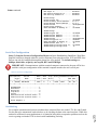
208V/48A Rated Model:
(60A Maximum Over current protection Device).
208V/40A Rated Model:
(50A Maximum Over current protection Device).
208V/24A Rated Model:
(30A Maximum Over current protection Device).
208V/16A Rated Model:
(20A Maximum Over current protection Device)
208V/12A Rated Model:
(15A Maximum Over current protection Device)
400V/16A Rated Model:
(20A Maximum Over current protection Device)
120V/24A Rated Model:
(30A Maximum Over current protection Device)
120V/16A Rated Model:
(20A Maximum Over current protection Device)
Unit Processors Page
9 The unit controller has two processors, Ethernet and Outlet processors. Both processors are flash
upgradable via Ethernet port. Power strips with only a Serial port must be connected to a Master unit or
Baytech Data Switch to upgrade the Outlet Controller. You may contact Baytech Technical Support for the
latest firmware.
Each Outlet Modules has a processor that communicates with the Outlet Controller. This processor cannot
be upgraded in the field. If an upgrade is needed, Baytech Technical Support will be contacted you.
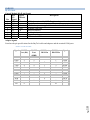
CABLING RJ45 Cable Control Module RJ-45 pin Signals
EIA
Signal
Description
232
Directio
Pin
Signal
n
1
DTR
Out
+10V when activated by DCD. Toggles on logout for modem disconnect.
2
GND
Signal Ground
3
RTS
Out
+10 V when power is applied. Not used as a handshake line.
4
TX
Out
Transmit (Data Out)
5
RX
In
Receive (Data In)
6
N/C
In
No Connection.
7
GND
Signal Ground
8
DCD
In
DCD into the MRP.
Adapter signals
Listed are the pin specifications for the BayTech cable and adapters and the terminal COM ports:
RS-232
Port (DS)
DTR
GND
RTS
TXD
RXD
DSR
GND
CTS
DTR
DCD
RI
1
2
3
4
5
6
7
8
RS-232
Port
(MRP)
1
2
3
4
5
N/C
7
8
9
COM Port
DE-9 Pin
COM Port
DB-25 Pin
Signal
4
20
1
5
2
3
6
7
4
DSR
GND
CTS
RXD
TXD
DTR
GND
RTS
DCD
DTR
7
3
2
6
5
8
4
1
8
22
Page
Signal
10 Serial 1: Port Pin out Table
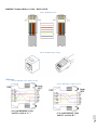
RJ08X007 Standard Rollover Cable – RJ45 to RJ45
Serial 2: RJ08X007 Pin out
Serial 3: RJ45 Receptacle & Plug
Adapters Serial 4: 9FRJ45PC Cisco Adapter Pin Out
(Use with RJ08X007 Cable
And B/C switch in B”)
Page
(Use with RJ08X007 Cable
And B/C switch in “C”)
11 Serial 5: 9FRJ45PC-1 Adapter Pin out
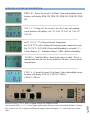
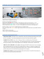
Rack Mount Hardware Tool Less hardware installed on back of unit. If hardware is not needed, remove with
Phillips screwdriver.
Instructions to install M140C138 brackets to the Baytech vertical power strip.
In each unit locate the small bubble wrapped brackets containing two brackets and four screws. See
figure 1 and 2.
Figure1
Figure2
Line up the bracket holes to the holes on the unit. Figure 3.
Figure 3
Screw in two screws. Figures 4, 5, & 6 show the bracket mounted in three different positions.
Figure 4
Figure 5
Page
12 Figure 6
SERIAL SETUP
Connect the 9FRJ45PC-1 adapter to the user’s computer
Connect the RPC EIA-232 port to the adapter via the RJ08X007 rolled flat ribbon cable.
Use terminal emulation software to access the unit, 9600 bps, 8 data bits, 1stop bit, no parity,
no flow control, and B/C switch set to ‘B’.
NOTE: At any time during the session you need to go to another menu, use the Attention
Character = semi-colon (;). Press the attention character key 5-times to get back to the
main status menu.
IMPORTANT: If a device, other than a PC, is used to connect to the serial EIA232 port, a
custom cable is needed; see Serial 1 figure above, for serial port pin out.
IMPORTANT: Do not connect both ends of the 8” serial cable until after the MASTER
unit has been configured.
Operation Important: When operating remotely, do not send the command to turn “off” a receptacle that has a host terminal
or modem attached. Doing so will result in the host terminal or modem being powered down creating
a “locked-out” condition. You will not be able to reestablish a connection until the receptacle has
been turned “on” through the serial port.
IMPORTANT: If you send the command to “reboot” a receptacle with a host terminal or
modem attached, active connection to that terminal or modem is lost and will have to be
reestablished.
IMPORTANT: An assigned user is allowed one active session. The admin user is allowed
four sessions running concurrently.
The green LED’s correspond to the unit’s receptacles. An illuminated LED signifies the
corresponding outlet has power turned on, thus the attached equipment has power to it. No lit LED
signifies no power to the receptacle.
Outlet Status The Modular Series are multi-user units, supporting one admin user and up to Thirty-two outlet users.
The admin user has access to all outlets, user and system configuration options, unit status, and unit
reset capabilities. The outlet user’s status menu displays only those outlets assigned to the user’s
outlet list, as set by the admin user.
NOTE: The Modular Series supports one admin user. The admin user may have four sessions
running concurrently. Default user name is ‘root’. User names are case sensitive.
Page
NOTE: The Modular Series menu is used for demonstration throughout this manual. There will
be some differences in the menus dependent on the firmware revision and the number of outlets
on your unit.
13 NOTE: Each session has an inactivity timeout of ten minutes, if there is no option to set the
timeout. After ten minutes of no activity elapses, the session terminates.
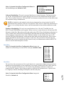
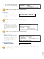
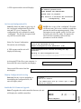
QUICK START: MRP SERIES For those Administrators who have requested the bare minimum for this type of equipment, follow these
steps exactly. If this is a new unit shipped directly from Baytech, follow the steps. If this is a previously
own unit, perform a factory reset to clear out any users and passwords still in the unit.
Outlet Control Configuration: 1. Connect the 9FRJ45PC-4 or 9FRJ45PC-1 adapter to your PC.
2. Connect the supplied rollover flat cable RJ08X007 to the adapter and to the EIA232 serial port
on the Baytech MRP device.
3. Use terminal emulation software to access the unit, (i.e. Microsoft Hyper-terminal). Set the PC
serial port configuration to the following: 9600 bps, 8 data bits, 1stop bit and no parity. If
your device has a B/C switch near the EIA232 port, set it to ‘B’.
4. If you get only a blinking cursor Press ‘Enter’. If still only a blinking cursor, Type 5 semicolons (;), there is a one second delay before the menu is displayed.
5. You should get the Outlet Status menu (Figure 1). This is the outlet controller circuits. If you
get the Network Menu (Figure 7), select option 1, Outlet Control or Unit (MRP 10 (2, 1) . . .
1) to get to the Outlet Status menu.
6. At prompt type ‘config’ and press ‘Enter’. You should see a menu similar to (Figure 4).
7. Select number for the Manage Users option. You should see a menu similar to (Figure 5).
8. IMPORTANT NOTE: the first user added will be the ADMIN user. Type “A” and press
‘Enter’. Type the name of the admin user. The name is case sensitive.
9. Select the user number. You should see the user in the menu similar to (Figure 6).
10. Select ‘Add Outlet(s)’ to add a few outlets (i.e. 1, 2, 4) and press ‘Enter’ or select ‘Add All
Outlet’. A “Y” signifies the outlet has been assigned to the user.
11. Press ‘Enter’ you should see a menu similar to (Figure 5) with the user name. Repeat steps 7
thru 10 to add other users.
12. Once you have added the users press ‘Enter’ until you get back to the Outlet Status menu,
(Figure 1). Type “Exit”. With (Microsoft Hyper-terminal) pressing ‘Enter’ will reconnect to
the unit outlet controller and it will ask for a use name. If this does not happen close the
terminal emulator session and open it again.
13. Type the name of a user to log in. You should see a menu similar to (Figure 1). The user will
see only the outlets assigned to them.
14. At the prompt type ‘password’ and press ‘Enter’. You should see prompts similar to
(Figure 3).
15. Enter the password for the user. Repeat steps 12 thru 14 to add or change the password of the
user.
Page
14 At this point you have enough Outlet Control Configurations to operate this Baytech Device.
Continue to the Ethernet Controller Configuration if your unit has an Ethernet port.
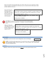
This is the bare minimum for Ethernet Control. If this is a new unit shipped directly from Baytech, follow
the steps. If this is a previously own unit, perform a factory reset to clear out any users and passwords still
in the unit. The System Administrator should tell you to use DHCP or provide you an IP Address, Subnet
Mask, and Gateway Address. NOTE: default IP Address is 0.0.0.0
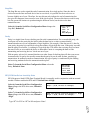
Ethernet Configuration: Before continuing your System Administrator needs to tell you to use DHCP or give you an IP
Address, Subnet Address, and Gateway Address.
1. If this Baytech device has an Ethernet port, at the prompt of any menu type five Attention
Characters (factory default is the semi-colon, {;}). The Attention Character will not echo on
the screen. You should see a menu similar to (Figure 7).
2. Select ‘C’ for the configuration menu. You should see a menu similar to (Figure 8).
3. Select the number for ‘Login Setup’ option. You should see a menu similar to (Figure 9).
4. Select the number for ‘Manage Users’ option. You should see a menu similar to (Figure 12).
5. NOTE: The ‘root’ user can not be deleted.
6. Select ‘A’ to add user. Type the name and password at the prompts.
7. Press ‘Enter’ until get to the ‘Login Setup Menu’ (Figure 9).
8. Select ‘Access Control’ to enable or disable the Tenet and Serial Login Prompt (Figure 10).
9. Press ‘Enter’ until you get the Configuration menu (Figure 8).
10. Select ‘Network Port Configuration’ option. You should see a menu similar to (Figure 13).
11. If your System Administrator requires you to use DHCP, then select ‘DHCP Enable/Disable’
and type “Y” to enable DHCP. If you wish to assign a static IP address to this unit, Disable
the DHCP and go to step 15.
12. Press ‘Enter’ until you are asked to ‘Accept Changes’. Type “Y” to accept changes or “N” to
decline changes.
13. After Accepting or Declining Changes you should get the Network Access Menu (Figure 7).
14. Select ‘Unit reset’ to update the external connections. Once the reset is completed (1 minute)
connect the Baytech device to your network using an Ethernet cable.
15. If you disabled the DHCP in step 11, you should see a menu similar to (Figure 13).
16. Select the ‘IP Address’ option and type the assigned IP address and press ‘Enter’.
17. Select the ‘Subnet Mask’ option and type the assigned subnet mask address and press ‘Enter’.
18. Select the ‘Gateway Address’ option and type the assigned Gateway address and press ‘Enter’.
19. Press ‘Enter’ until you are asked to ‘Accept Changes’. Type “Y” to accept changes.
20. Select ‘Unit reset’ to update the external connections. Once the reset is completed (1 minute)
connect the Baytech device to your network using an Ethernet cable.
21. You should be prompted for a user name and password, similar to (Figure 11)
Page
15 At this point you have enough basic configurations needed to operate this Baytech unit.
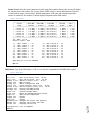
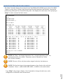
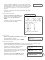
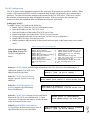
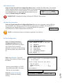
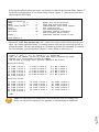
Status Screen: Once the serial connection is made using the terminal software, the screen will display
the inherent state of the outlets, the Average Power, RMS voltage, Current and Maximum Detected
Current both in Amps, circuit breaker, Internal temperature of the unit, and external temperature
sensors if connected. The number of outlets displayed depends on the MRP model.
Figure 1: Outlet Status
Total kW-h:
0
------------------------------------------------------------------------------|
Circuit
| True RMS | Peak RMS | True RMS
|
Average | Volt- |
|
Group
| Current | Current |
Voltage
|
Power
| Amps
|
------------------------------------------------------------------------------|
Circuit C1
| 0.0 Amps | 0.0 Amps | 209.5 Volts |
0 Watts |
4 VA |
|
Circuit C2
| 0.0 Amps | 0.0 Amps | 209.5 Volts |
0 Watts |
4 VA |
|
Circuit C3
| 0.0 Amps | 0.0 Amps | 209.5 Volts |
1 Watts |
4 VA |
|
Circuit C4
| 0.0 Amps | 0.0 Amps | 207.3 Volts |
0 Watts |
4 VA |
|
Circuit C5
| 0.0 Amps | 0.0 Amps | 208.3 Volts |
1 Watts |
4 VA |
|
Circuit C6
| 0.0 Amps | 0.0 Amps | 209.6 Volts |
0 Watts |
4 VA |
------------------------------------------------------------------------------Int. Temp: 77.9 F
Switch 1: Open 2: Open
1)...CKT
3)...CKT
5)...CKT
7)...CKT
9)...CKT
11)...CKT
13)...CKT
15)...CKT
17)...CKT
19)...CKT
1
1
2
2
3
3
4
4
5
5
Outlet
Outlet
Outlet
Outlet
Outlet
Outlet
Outlet
Outlet
Outlet
Outlet
1
3
1
3
1
3
1
3
1
3
:
:
:
:
:
:
:
:
:
:
On
On
On
On
On
On
On
On
On
On
2)...CKT
4)...CKT
6)...CKT
8)...CKT
10)...CKT
12)...CKT
14)...CKT
16)...CKT
18)...CKT
20)...CKT
1
1
2
2
3
3
4
4
5
5
Outlet
Outlet
Outlet
Outlet
Outlet
Outlet
Outlet
Outlet
Outlet
Outlet
2
4
2
4
2
4
2
4
2
4
:
:
:
:
:
:
:
:
:
:
On
On
On
On
On
On
On
On
On
On
Type Help for a list of commands
MRP-20>
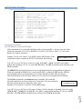
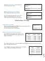
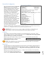
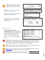
Help Menu: Type Help followed by a <CR> to view the line commands for the MRP outlet control.
Figure 2: Outlet Help
MRP-20>help
Type Help for a list of commands
MRP-20>
16 --Turn on an Outlet, n=0,1...36,all
--Turn off an Outlet, n=0,1...36,all
--Reboot an Outlet, n=0,1...36,all
--MRP-10 Status
--Enter configuration mode
--Locks Outlet(s) state, n=0,1...36,all
--Unlock Outlet(s) state, n=0,1...36,all
--Display True RMS Current
--Display True RMS Voltage
--Display Average Power
--Reset the maximum detected current
--Read current temperature
--Logoff
--Logoff
--Logoff
--Changes the current user password
--Displays the current user name
--Displays the unit ID
Page
On n <cr>
Off n <cr>
Reboot n <cr>
Status <cr>
Config <cr>
Lock n <cr>
Unlock n <cr>
Current <cr>
Voltage <cr>
Power <cr>
Clear <cr>
Temp <cr>
Logout <cr>
Logoff <cr>
Exit <cr>
Password <cr>
Whoami <cr>
Unitid <cr>
Password setting: Once you have logged out and log back in as a user or as the
administrator, you can then set the password to gain access. Type “Password”<cr>
Figure 3: Outlet Password
MRP>password
Enter new Password: *****
Re-Enter new Password: *****
Type Help for a list of commands
MRP>
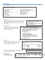
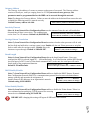
Power Controller Configuration Menu: To select the configuration menu, type ‘config’ at
the prompt.
NOTE: If the unit display with the following message, “Configuration mode in use”
A user in the other port is in the “Configuration” menu.
Figure 4: Outlet Configuration
MRP>config
Unit ID: MRP20
1)...Manage Users
2)...Change Outlet Name
3)...Enable/Disable Confirmation
4)...Enable/Disable Status Menu
5)...Change Unit ID
6)...Change Alarm Threshold
7)...Change Display Orientation
X)...Exit
Add/Delete/Rename, assign outlets
Select an outlet to change its name
Confirmation (Y/N)
Opening status of outlets
As written
As written
Flip Display
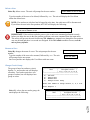
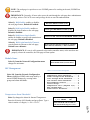
Manage User
The User Menu allows the admin user to add and delete users, change passwords, and change the outlet
list that displays a user’s access to prescribed outlets. Select “Manage Users,” from the configuration
menu and the following menu appears if the unit has been reset or initial setup:
Figure 5: Outlet Manage User
------------------------------------------|
User
|
Assigned Outlets
|
|
| C1,1| C1,2| C1,3| C1,4|
------------------------------------------------------------------------------------A)...Add User
D)...Delete User
R)...Rename User
C)...Change Circuit Group
Enter user number to assign Outlets, A, D, C or R.
Enter Request:
Select A), “Add user,” from the User Management Menu.
Enter the name of the user to be added, followed by <cr>.
NOTE: User name is
case sensitive.
Page
Add a User:
17 NOTE: User in position (1) will be the ‘admin user’ for the outlets. Older units will not display
the ‘delete’ option until a user is added.
Assigned Outlets
Select a user number from the User Management Menu, the MRP unit will display the Assign Outlet
Menu:
Figure 6: Outlet Assignment
------------------------------------------|
User
|
Assigned Outlets
|
|
| C1,1| C1,2| C1,3| C1,4|
------------------------------------------1) engineer
| N | N | N | N |
------------------------------------------1)...Add Outlet(s)
Add individual Outlets (X, X, X, X)
2)...Remove Outlet(s)
Remove individual Outlets
3)...Add All Outlets
Add all outlets to above user
4)...Remove All Outlets
Remove all Outlets from the above user
C)...Change Circuit Group Display next Circuit group of outlets
Enter Request:
NOTE: If an outlet user’s list is changed while the user is logged in, their outlet list changes
dynamically. If enabled, an updated outlet status report will be issued. “Y” means the outlet is
assigned to the user. “N” means the outlet is NOT assigned to the user.
Change Outlet Name: Allows the administrator to change the name of the outlets.
Enable/Disable Confirmation: Enables/Disables the confirmation of choices. Example, “Turn off all
outlets [Y/N]?”
Enable/Disable Status Menu; Enables/Disables whether outlet status menu is displayed.
Change Unit ID: Allows the user to change the name of the unit. The defaulted is something similar
to MRP1. Allows the user to personalize or customize name or location, up to 31 alphanumeric
characters.
Change Alarm Threshold: The Alarm Threshold is the value set that sounds the amperage alarm
when it reaches or exceeds the amperage value indicated.
Change Circuit Group: Allows user to flip the display for units with cords going out the top of
cabinets.
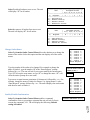
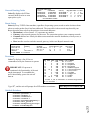
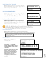
Universal Ethernet Controller Configuration:
Access Menu: The Access Menu screen, allows for Outlet Operations, Network Configuration, or
Disconnection. To access the Network Configuration Screen, type five Attention Characters.
Page
18 NOTE: For initial network access, the IP address, subnet mask, and gateway must be
configured from the serial port. Default setting is 0.0.0.0.
Figure 7: Network Menu
Module: 1
Attention Character: ;
MRP20
(2 ,1).........1
Status..........................S
Configure.......................C
Unit Reset......................RU
Unit Status
Unit Configuration menu
Terminates external connections,
does not affect outlet states.
Logout..........................T
Enter Request :s
Figure 8: Network Configuration
Copyright(C) Bay Technical Associates 2008
URPC Ethernet Host Module
Revision F 2.25.06
Module 1
Hardware 1.00
Serial number 22222
Status..........................1
Serial Port Configuration.......2
Serial Port Device Name.........3
Attention Character.............4
Disconnect Timeguard............5
Connect Port ID Echo............6
Login Setup.....................7
Network Port Configuration......8
Module Name.....................9
MRP Management.................10
Firmware / Config Download.....11
Exit.........................X,CR
Enter Request :
colilo version 1.05.01
Status of all network options
Setup the Serial port EIA232
Change the EIA232 port name
Type 5 times to access Network Main menu.
Data received within the delay period,
is data, not attention character; thereby
preventing unwanted port disconnection
Echo port name or module# & port#
Login Menu Serial/Telnet/Radius/TACACS
access control, manage users
Network Port IP Address
Change name of module
Set up Voltage/Current/Sensor threshold
Update Firmware, SSL, Configuration files
Login Setup Menu
Figure 9: Network Login Setup
Access Control..................1
Manage Users....................2
Radius Configuration............3
TACACS Configuration............4
Exit............................X,CR
Access Control
Enable or disable usernames and passwords for both network and serial port access. If either login has
been enabled you will get a prompt similar to the following:
Figure 10: Network Access Control
Telnet Login Prompt Enable/Disable..1
Serial Login Prompt Enable/Disable..2
The default user and password is “root/baytech”, all lower case.
Page
Universal RPC login:
Password:
19 Figure 11: Network Login Prompt
Manage Users
Add/delete users and change their passwords. Usernames and passwords are case sensitive and
alphanumeric. The root user can not be removed.
Figure 12: Network Manage Users
User Management Menu
To change user password or port access, enter number of user.
To add/delete user, select appropriate menu choice.
SNMP V3 requires passwords that are between 8 and 31 characters long
Enter request, CR to exit menus.
A)...Add user
1)...root
Network Port Configuration
For network access, you must configure the IP addresses, Subnet Mask, and Gateway Address, or
enable the DHCP. The Changes must be saved and the module reset for network changes to take effect.
Figure 13: Network Port Configuration
Network setup :
Ethernet Address................
IP Address......................
Subnet Mask.....................
Default Gateway.................
00:C0:48:00:01:FD
70.150.140.89
255.255.255.224
70.150.140.65
Connection Inactivity Timeout (mins): Disabled
Carriage Return Translation: Enabled
Break Length (msecs): 350
DHCP is Disabled
Telnet is Enabled
SSH is Enabled
SSH host keys are set to factory default
IP Address........................1
Subnet Mask.......................2
Gateway Address...................3
Inactivity Timeout................4
Carriage Return Translation.......5
Break Length......................6
DHCP Enable/Disable...............7
Telnet Enable/Disable.............8
SSH Enable/Disable................9
SSH Host Key Generation...........10
IP Filter Configuration...........11
SNMP Configuration................12
Web Server Configuration..........13
Exit..............................X,CR
Page
20 Enter Request :
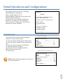
Detail Operations and Configurations After logging into the unit, the unit will display
additional hardware information:
Outlet controller firmware, F1.11
Options installed Voltage and Current sensors and
Internal Temperature Sensor.
(Opening access to internal RPC) signifies the
processor is checking to see what is installed.
“Enter user name:” will appear if a user has been
assigned to the Outlet Controller
Universal RPC login: root
Password:
BAYTECH
For further information check:
http://www.baytech.net/
opening access to internal RPC
MRP-27 Series
(C) 2008 BayTech
F1.11
Option(s) Installed:
True RMS Voltage
True RMS Current
Internal Temperature
Enter user name:
NETWORK MENU Single Unit Menu
CASCADE ENABLED Menu
Module: 1
Attention Character:
MRP27
(2 ,1).........1
MRP27
(2 ,2).........2
Outlet Group Control............O
Status..........................S
Configure.......................C
Unit Reset......................RU
Logout..........................T
Enter Request :s
21 NOTE: Option (2) and option (O) are for units set
for Cascade operations.
Module: 1
Attention Character: ;
MRP27
(2 ,1).........1
Status..........................S
Configure.......................C
Unit Reset......................RU
Logout..........................T
Enter Request :
Page
The Network menu can be accessed through the
Ethernet or Console (EIA232) port.
1), opens the Outlet Controller Menu, Ethernet unit.
2), opens the Outlet Controller Menu, Non-Ethernet
unit.
O), opens the Cascade Outlet Controller Menu.
S), opens the Ethernet data Status.
C), opens the Network Configuration Menu.
RU), opens the reset decision.
T), close session
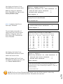
OUTLET CONTROLLER STATUS SCREEN The Outlet Controller displays the measured circuit True RMS and Peak RMS current values; True RMS
Voltage; Average Power, Voltage/Amps; Internal and External temperature and Humidity with attached
probes; along with Open/Close external Switch probes. Also displays the outlet status. At the prompt type
“Help” for outlet command and other menus.
MRP-10 Series
(C) 2008 BayTech
F1.12
True RMS Voltage
True RMS Current
Internal Temperature
Unit ID: MRP-10
Total kW-h: 8731
------------------------------------------------------------------------------|
Circuit
| True RMS | Peak RMS | True RMS
|
Average | Volt- |
|
Group
| Current | Current |
Voltage
|
Power
| Amps
|
------------------------------------------------------------------------------|
Circuit M1
| 0.0 Amps | 0.0 Amps | 196.7 Volts |
0 Watts |
4 VA |
|
Circuit M2
| 0.0 Amps | 0.0 Amps | 200.8 Volts |
0 Watts |
4 VA |
|
Circuit M3
| 0.0 Amps | 0.0 Amps | 200.3 Volts |
0 Watts |
4 VA |
|
Circuit M4
| 0.0 Amps | 0.0 Amps | 199.4 Volts |
0 Watts |
4 VA |
|
Circuit M5
| 0.0 Amps | 0.0 Amps | 198.6 Volts |
0 Watts |
4 VA |
|
Circuit M6
| 0.0 Amps | 0.0 Amps | 199.6 Volts |
0 Watts |
4 VA |
------------------------------------------------------------------------------Int. Temp: 115.7 F
1)...MOD 1 Outlet
3)...MOD 1 Outlet
5)...MOD 2 Outlet
7)...MOD 2 Outlet
9)...MOD 3 Outlet
11)...MOD 3 Outlet
13)...MOD 4 Outlet
15)...MOD 4 Outlet
17)...MOD 5 Outlet
19)...MOD 5 Outlet
21)...MOD 6 Outlet
23)...MOD 6 Outlet
1
3
1
3
1
3
1
3
1
3
1
3
Ext. 1:
: On
: On
: On
: On
: On
: On
: On
: On
: On
: On
: On
: On
74.7 F : 52.7% RH
2)...MOD
4)...MOD
6)...MOD
8)...MOD
10)...MOD
12)...MOD
14)...MOD
16)...MOD
18)...MOD
20)...MOD
22)...MOD
24)...MOD
1
1
2
2
3
3
4
4
5
5
6
6
Ext. 2:
Outlet
Outlet
Outlet
Outlet
Outlet
Outlet
Outlet
Outlet
Outlet
Outlet
Outlet
Outlet
2
4
2
4
2
4
2
4
2
4
2
4
72.0 F
: On
: On
: On
: On
: On
: On
: On
: On
: On
: On
: On
: On
Type Help for a list of commands
MRP-10>
NOTE: Int. Temp = unit internal temperature. Ext = external temperature probe. Two
environmental ports are available. Temperature reads in Fahrenheit or Celsius.
RH = Relative humidity.
NOTE: The user will see only those outlets assigned to them by the admin user.
NOTE: The first three letters in the prompt designate a class of units with a sub-class
of numbers. Classes = (MDP, MMP, MRP, MSP); i.e. MRP10 is the model number.
Page
22 Type “Help” at the prompt to display a list of commands to change the outlet state, outlet
configuration, and internal sensor measurements.
OUTLET HELP OPTIONS Outlet 1: Outlet Control Help
On n <cr>
Off n <cr>
Reboot n <cr>
Status <cr>
Config <cr>
Lock n <cr>
Unlock n <cr>
Current <cr>
Voltage <cr>
Power <cr>
Clear <cr>
Temp <cr>
Logout <cr>
Logoff <cr>
Exit <cr>
Password <cr>
Whoami <cr>
Unitid <cr>
--Turn on an Outlet, n=0,1...24,all
--Turn off an Outlet, n=0,1...24,all
--Reboot an Outlet, n=0,1...24,all
--MRP-10 Status
--Enter configuration mode
--Locks Outlet(s) state, n=0,1...24,all
--Unlock Outlet(s) state, n=0,1...24,all
--Display True RMS Current
--Display True RMS Voltage
--Display Average Power
--Reset the maximum detected current
--Read current temperature
--Logoff
--Logoff
--Logoff
--Changes the current user password
--Displays the current user name
--Displays the unit ID
Receptacle Controls On, Off, Reboot, Lock, and Unlock These commands are to control the individual outlets. From the (MRP >) prompt, enter one of the
following commands: ON n, OFF n, REBOOT n, LOCK n, UNLOCK n, where “n” is the outlet
number you want to command.
Example: To turn “On” Outlet 3, type ON 3 from the MRP prompt. If the
confirmation option is turned on, the UNIT will display the following:
Turn On Outlet 3 (Y/N)?
Type “Y” for yes or “N” for no. Likewise, typing “ON ALL”, “ON 0”, or “ON” at the MRP >
prompt and responding “Y” for yes, turns ‘On’ all outlets. The OFF n command work similarly as the
ON n command.
The REBOOT n command will reboot or reset equipment attached to corresponding receptacle(s).
When the command to REBOOT (n) is sent from the MRP > prompt, the MRP powers ‘Off’ the
corresponding outlet(s) for approximately 10 seconds, then powers them ‘On’ in sequence.
This command only works on outlets which were ‘On’ prior to receiving the reboot command.
The LOCK n command is an admin user only command. This command
allows the admin user to lock an outlet in its current state. The user assigned to
the outlet will not be able to change the outlet’s state.
Example: To lock Outlet 1, type lock 1 at the MRP prompt.
MRP10>lock 1,
Lock Outlet 1 (Y/N)? y
Page
23 Type “Y” for yes or “N” for no. The status of Outlet 1 will be changed to ‘Locked’. Likewise, typing
“LOCK ALL”, “LOCK 0”, or “LOCK” at the MRP > prompt and responding “Y” for yes, ‘Locks’
all outlets. The UNLOCK n command works similarly as the LOCK n command.
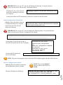
STATUS Total kW-h:
0
------------------------------------------------------------------------------|
Circuit
| True RMS | Peak RMS | True RMS
|
Average | Volt- |
|
Group
| Current | Current |
Voltage
|
Power
| Amps
|
------------------------------------------------------------------------------|
Circuit C1
| 0.0 Amps | 0.7 Amps | 202.2 Volts |
0 Watts |
4 VA |
|
Circuit C2
| 0.0 Amps | 0.0 Amps | 204.1 Volts |
0 Watts |
4 VA |
|
Circuit C3
| 0.2 Amps | 0.5 Amps | 202.9 Volts |
0 Watts |
52 VA |
|
Circuit C4
| 0.6 Amps | 0.9 Amps | 202.3 Volts |
50 Watts | 123 VA |
|
Circuit C5
| 1.3 Amps | 1.8 Amps | 203.7 Volts |
92 Watts | 265 VA |
|
Circuit C6
| 0.9 Amps | 1.4 Amps | 206.0 Volts |
74 Watts | 199 VA |
------------------------------------------------------------------------------Int. Temp: 95.9 F Ext. 1: 72.3 F : 31.5% RH Ext. 2: 71.1 F
1)...Outlet 1
: On
2)...Outlet 2
: On
3)...Outlet 3
: On
4)...Outlet 4
: On
5)...(RIGHT) Outlet : On
6)...Outlet 6
: On
7)...Outlet 7
: On
8)...Outlet 8
: On
9)...Outlet 9
: On
10)...Outlet 10
: On
11)...Outlet 11
: On
12)...(LEFT) Outlet 1 : On
13)...Outlet 13
: On
14)...Outlet 14
: On
15)...Outlet 15
: On
16)...Outlet 16
: On
17)...Outlet 17
: On
18)...Outlet 18
: On
19)...Outlet 19
: On
20)...Outlet 20
: On
21)...Outlet 21
: On
22)...Outlet 22
: On
23)...Outlet 23
: On
24)...Outlet 24
: On
25)...Outlet 25
: On
26)...Outlet 26
: On
27)...Outlet 27
: On
28)...Outlet 28
: On
29)...Outlet 29
: On
30)...Outlet 30
: On
Total kW-h:
10
-----------------------------------------|
Circuit
| True RMS | Peak RMS |
|
Breaker
| Current | Current |
-----------------------------------------|
CKT1
| 0.3 Amps | 0.6 Amps |
|
CKT2
| 0.6 Amps | 0.7 Amps |
------------------------------------------------------------------------------|
Circuit
| True RMS | Peak RMS | True RMS
|
Average | Volt- |
|
Group
| Current | Current |
Voltage
|
Power
| Amps
|
------------------------------------------------------------------------------|
Circuit M1
| 0.2 Amps | 0.3 Amps | 128.2 Volts |
10 Watts |
27 VA |
|
Circuit M2
| 0.0 Amps | 0.1 Amps | 218.9 Volts |
0 Watts |
3 VA |
|
Circuit M3
| 0.1 Amps | 0.1 Amps | 219.6 Volts |
0 Watts |
31 VA |
|
Circuit M4
| 0.2 Amps | 0.2 Amps | 221.7 Volts |
0 Watts |
44 VA |
|
Circuit M5
| 0.2 Amps | 0.2 Amps | 223.0 Volts |
0 Watts |
53 VA |
|
Circuit M6
| 0.2 Amps | 0.2 Amps | 222.7 Volts |
0 Watts |
52 VA |
------------------------------------------------------------------------------Int. Temp: 89.6 F
Switch 1: Open 2: Open
1)...MOD
3)...MOD
5)...MOD
7)...MOD
9)...MOD
11)...MOD
13)...MOD
15)...MOD
17)...MOD
19)...MOD
21)...MOD
23)...MOD
25)...MOD
27)...MOD
29)...MOD
31)...MOD
33)...MOD
1
1
1
2
2
2
3
3
3
4
4
5
5
5
6
6
6
Outlet
Outlet
Outlet
Outlet
Outlet
Outlet
Outlet
Outlet
Outlet
Outlet
Outlet
Outlet
Outlet
Outlet
Outlet
Outlet
Outlet
1
3
5
1
3
5
2
4
6
2
4
1
3
5
1
3
5
:
:
:
:
:
:
:
:
:
:
:
:
:
:
:
:
:
On
On
On
On
On
On
On
On
On
On
On
On
On
On
On
On
On
2)...MOD
4)...MOD
6)...MOD
8)...MOD
10)...MOD
12)...MOD
14)...MOD
16)...MOD
18)...MOD
20)...MOD
22)...MOD
24)...MOD
26)...MOD
28)...MOD
30)...MOD
32)...MOD
1
1
1
2
2
3
3
3
4
4
4
5
5
5
6
6
Outlet
Outlet
Outlet
Outlet
Outlet
Outlet
Outlet
Outlet
Outlet
Outlet
Outlet
Outlet
Outlet
Outlet
Outlet
Outlet
2
4
6
2
4
1
3
5
1
3
5
2
4
6
2
4
:
:
:
:
:
:
:
:
:
:
:
:
:
:
:
:
On
On
On
On
On
On
On
On
On
On
On
On
On
On
On
On
24 A unit with less than (6)
circuit breakers will show the
current status of the breakers
and all circuit module level. It
shows Circuit Groups, True
RMS Current, Peak RMS
Current, True RMS Voltage,
Average Power, and VoltAmps. Status also shows
whether the outlets are on, off,
or locked
Unit ID: MRP10
Page
This shows the current status
of all circuit to the circuit
breaker level. It shows Circuit
Groups, True RMS Current,
Peak RMS Current, True RMS
Voltage, Average Power, and
Volt-Amps. Status also shows
whether the outlets are on, off,
or locked.
Outlet Control Configuration Menu To select the configuration menu, type ‘config’ at the prompt.
NOTE: If the unit display with the following message, “Configuration mode in use”
Another user is in the other port in the “Configuration” menu.
Outlet 2: Outlet Configuration
Unit ID: MRP Power-20
1)...Manage Users
2)...Change Outlet Name
3)...Enable/Disable Confirmation
4)...Enable/Disable Status Menu
5)...Change Unit ID
6)...Change Alarm Threshold
7)
Change Display orientation
X)...Exit
Add/Delete/Rename, assign outlets
Select an outlet to change its name
Confirmation (Y/N)
Opening status of outlets
As written
As written
As written
Manage Users Outlet 3: Outlet Manage Users
Select 1), from the Outlet Control Menu
allows the admin user to add and delete users,
change passwords, and change the outlet list
that displays a user’s access to prescribed
outlets. Select “Manage Users,” from the
configuration menu and the following menu
appears if the unit has been reset or initial
setup:
-------------------------------------------------|
User
|
Assigned Outlets
|
|
| C1,1| C1,2| C1,3| C1,4|
--------------------------------------------------------------------------------------------------A)...Add User
D)...Delete User
R)...Rename User
C)...Change Circuit Group
Enter user number to assign Outlets, A, D, C or R.
Enter Request:
Add a User: Enter user name:
-------------------------------------------|
User
|
Assigned Outlets
|
|
| C1,1| C1,2| C1,3| C1,4|
-------------------------------------------1...Engineer
| N | Y | N | Y |
-------------------------------------------A)...Add User
D)...Delete User
R)...Rename User
C)...Change Circuit Group
Enter user number to assign Outlets, A, D, C or R.
Enter Request:
25 Type the user name followed by <cr>.
NOTE: User name is case sensitive. The
unit will display the User Menu with the
added user name.
NOTE: the first assigned user will be the
‘admin user’ for the outlets. Older units
will not display the ‘delete’ option unit a
user is added.
Page
NOTE: If the “Add user” option is NOT
present than the maximum number of
users have been assigned. You will get a
message saying ‘No more users can be
added’.
Select A), adds a user. The unit will
prompt for a user name:
Delete a User: Select D), deletes a user. The unit will prompt for the user number:
Enter number for user to delete:
Type the number of the user to be deleted, followed by <cr>. The unit will display the User Menu
minus the deleted user.
NOTE: If an outlet user is deleted and is logged in at the time, the outlet user will be disconnected.
If you delete the user in the first position, the UNIT will display the following:
You are deleting the current admin user. The next user will become the admin user,
do you want to continue. (Y/N)?
IMPORTANT: If the unit has not had a power cycle or unit reset command performed recently,
before you delete the user in the first position, perform a unit reset command from the main menu.
This action will prevent the unit from having NO Admin user assigned even though the first position
user was deleted and there is a second user assigned. If the NO Admin condition occurs, reset the
unit to factory defaults.
Rename a User: Select R), changes the name of a user. The unit prompts for the user
number.
Type the number of the user to be renamed, followed by <cr>. The unit
will prompt for the new name:
Once accepted the unit displays the User Menu with new name
Enter user number to rename:
Enter user name:
Change Circuit Group: The group is based on outlets to circuit
breaker, i.e. one breaker unit will displays
all outlets. Two breaker units have two
groups of outlets, but will displayed one
group at a time.
-------------------------------------------|
User
|
Assigned Outlets
|
|
| C1,1| C1,2| C1,3| C1,4|
--------------------------------------------------------------------------------------A)...Add User
D)...Delete User
R)...Rename User
C)...Change Circuit Group
Enter user number to assign Outlets, A, D, C or R.
Enter Request: c
26 -------------------------------------------|
User
|
Assigned Outlets
|
|
| C2,1| C2,2| C2,3| C2,4|
---------------------------------------------------------------------------------------
Page
Select C), selects the next outlet group, the
unit displays the following:
-------------------------------------------|
User
|
Assigned Outlets
|
|
| C1,1| C1,2| C1,3| C1,4|
-------------------------------------------1)
Engineer
| N | Y | N | N |
-------------------------------------------A)...Add User
D)...Delete User
R)...Rename User
C)...Change Circuit Group
Enter user number to assign Outlets, A, D, C or R.
-------------------------------------------|
User
|
Assigned Outlets
|
|
| C1,1| C1,2| C1,3| C1,4|
-------------------------------------------1)
Engineer
| N | Y | N | N |
-------------------------------------------1)...Add Outlet(s)
2)...Remove Outlet(s)
3)...Add All Outlets
4)...Remove All Outlets
C)...Change Circuit Group
Select 1), assigns an outlet to a user. The unit will prompt for outlet number:
Type the number of the outlet to be assign. For
example, if you want engineer to have access to
Outlet (C1,2), enter the number 2, followed by
<cr>. If you want engineer to have access to
Outlets (C1,2), (C1,3), and (C1,4) enter the
numbers 2, 3, and 4 separated by commas
followed by <cr>.
The unit redisplays the Assigned Outlet Menu of
the user with a “Y” for the assigned outlets.
-------------------------------------------|
User
|
Assigned Outlets
|
|
| C1,1| C1,2| C1,3| C1,4|
-------------------------------------------1)
Engineer
| N | Y | N | N |
-------------------------------------------1)...Add Outlet(s)
2)...Remove Outlet(s)
3)...Add All Outlets
4)...Remove All Outlets
C)...Change Circuit Group
Select 2), removes individual outlets from a user. The unit will prompt for
outlet number
Type the number of the outlet to be removed from
the user’s access. For example, if you want to
remove Outlet (C1,2), enter the number 2,
followed by <cr>. If you want engineer to have
access to Outlets (C1,2), (C1,3), and (C1,4) enter
the numbers 2, 3, and 4 separated by commas
followed by <cr>.The unit redisplays the
Assigned Outlet Menu of the user with an “N” for
the outlets NOT assigned.
Enter Outlet number(s):
Enter Outlet number(s):
-------------------------------------------|
User
|
Assigned Outlets
|
|
| C1,1| C1,2| C1,3| C1,4|
-------------------------------------------1)
Engineer
| N | Y | N | N |
-------------------------------------------1)...Add Outlet(s)
2)...Remove Outlet(s)
3)...Add All Outlets
4)...Remove All Outlets
27 NOTE: If an outlet user’s list is changed while
the user is logged in, their outlet list changes
dynamically. If enabled, an updated outlet
status report will be issued. “Y” means the
outlet is assigned to the user. “N” means the
outlet is NOT assigned to the user.
Page
Assigned Outlets The Assigned Outlet Menu displays the outlets
a user can access.
Select a user number from the Managed User
Menu, the unit will display the Assign Outlet
Menu:
Select 3), adds all outlets to user access. The unit
will display “Y” for all outlets
-------------------------------------------|
User
|
Assigned Outlets
|
|
| C1,1| C1,2| C1,3| C1,4|
-------------------------------------------1)
Engineer
| Y | Y | Y | Y |
-------------------------------------------1)...Add Outlet(s)
2)...Remove Outlet(s)
3)...Add All Outlets
4)...Remove All Outlets
Select 4), removes all outlets from user access.
The unit will display “N” for all outlets
-------------------------------------------|
User
|
Assigned Outlets
|
|
| C1,1| C1,2| C1,3| C1,4|
-------------------------------------------1)
Engineer
| N | N | N | N |
-------------------------------------------1)...Add Outlet(s)
2)...Remove Outlet(s)
3)...Add All Outlets
4)...Remove All Outlets
Change Outlet Name Select 2), from the Outlet Control Menu allows the admin user to change the
names of the outlets. Select this option and the unit displays all of the outlet
names.
Type the number of the outlet to be changed. For example to change the
name of Outlet 4, type the number “4” at the “Enter Request” prompt,
followed by <cr>. The unit will ask if you want to modify the current name.
Type “N” to keep the same name, or type “Y” to change the name. “Y” will
cause the unit to prompt for a new name.
1)...Outlet 1
2)...Outlet 2
3)...Outlet 3
4)...Outlet 4
5)...Outlet 5
6)...Outlet 6
7)...Outlet 7
8)...Outlet 8
Enter Request: 1
Current Outlet: Outlet 4
Modify (Y/N)? y
Enter :
Type a new receptacle name (maximum 16 characters), followed by <cr>. For
example, change the name of Outlet 4 to Router 1 by typing Router 1 at the
“Enter Request” prompt, followed by <cr>. The unit redisplays the outlet menu
with the new name to Outlet 4.
1)...Outlet 1
2)...Outlet 2
3)...Outlet 3
4)...Router 1
5)...Outlet 5
6)...Outlet 6
7)...Outlet 7
8)...Outlet 8
Enter Request: 1
Enable/Disable Confirmation 28 Enable Confirmation (Y/N)? y
Page
Select 3), from the Outlet Control Menu enables a command
confirmation. Prior to executing a command the unit will ask if what to
execute the command, Y/N.. The will display the following: Default
setting is Enabled.
Type “Y” to enable the confirmation option, or type “N” to disable. If the
confirmation feature is enabled and a command is sent to TURN ON, TURN
OFF, OR REBOOT a receptacle, the unit will ask to confirm the command.
For example, the command “ON 3” is sent, and the unit will display the
following:
If this feature is disabled, the unit will perform the command and redisplay
the previous menu.
Turn On Outlet 3? (Y/N)
Enable/Disable Status Menu Select 4), from the Outlet Control Menu enables
the Status menu. The unit will display the option to
change the current status: Default setting is
Enabled.
If this feature is disabled, only the prompt appears,
else the following status menu appears.
Enable Status Menu (Y/N)? y
Unit ID: MRP
-----------------------------------------|
Outlet
| True RMS | Peak RMS |
|
Group
| Current | Current |
-----------------------------------------| Outlet 1-8
| 0.2 Amps | 0.2 Amps |
-----------------------------------------Internal Temperature: 73.4 F
Switch 1: Open 2: Open
1)...Outlet
2)...Outlet
3)...Outlet
4)...Outlet
5)...Outlet
6)...Outlet
7)...Outlet
8)...Outlet
1
2
3
4
5
6
7
8
:
:
:
:
:
:
:
:
On
On
On
On
On
On
On
On
Type Help for a list of commands
MRP>
Change Unit ID Select 5), from the Outlet Control Menu changes the Unit ID.
The unit will display the following:
The default ID is the unit’s number, in this case MRP20
Current Unit ID: MRP20
Modify (Y/N)? y
Enter New Unit ID: Cab7_Rack1 MRP20
Change Alarm Threshold Select 6), from the Outlet Control Menu allows the user to set the current level for the internal alarm
to sound. This setting is only available on units with current monitoring circuitry.
If the number of circuit breakers DOES NOT equals the
number of modules, the unit will display the following:
Circuit C2 buzzer alarm value : 7.0 Amps
Modify (Y/N)? n
1)...Circuit Breaker Alarms
2)...Module/Group Circuit Breaker Alarms
29 Type “N” to keep the current value or type “Y” to change the
value and enter the new value, followed by ‘Enter’ and the
unit will display next circuit group.
Circuit C1buzzer alarm value : 12.0 Amps
Modify (Y/N)? y
Enter: 2.0
Page
If the number of circuit breakers equals the number of
modules, the unit will display the following:
Select 1), Circuit Breaker Alarms, changes the
alarm level per circuit breaker.
Circuit breaker 1 buzzer alarm value : 12.0 Amps
Modify (Y/N)? y
Enter: 15
Circuit breaker 2 buzzer alarm value : 12.0 Amps
Modify (Y/N)? y
Select 2), Module/Group Circuit Breaker Alarms changes the alarm level per module.
Type “N” to keep the current value or type “Y” to
change the value and enter the new value, press
“Enter’ and the unit will display next circuit group.
Circuit M1 buzzer alarm value : 12.0 Amps
Modify (Y/N)? y
Enter: 10
Circuit M2 buzzer alarm value : 12.0 Amps
Modify (Y/N)? y
Enter: 10
Default setting is 12.0 Amps.
Change Display Orientation Flip Display (Y/N)? y
Select 7), from the Outlet Control Menu flips the data displayed in the
LCD/LED screen on the unit controller.
The unit will display either of the following:
Or
Normal Display (Y/N)? y
Display Current Electrical Characteristics: Type “current” at the prompt to show the unit’s True
RMS Current and Peak RMS Current, and the unit will
display the following:
-----------------------------------------|
Circuit
| True RMS | Peak RMS |
|
Group
| Current | Current |
-----------------------------------------|
Circuit C1
| 0.0 Amps | 0.7 Amps |
|
Circuit C2
| 0.0 Amps | 0.0 Amps |
|
Circuit C3
| 0.1 Amps | 0.5 Amps |
|
Circuit C4
| 0.0 Amps | 0.9 Amps |
|
Circuit C5
| 1.2 Amps | 1.8 Amps |
|
Circuit C6
| 0.9 Amps | 1.4 Amps |
------------------------------------------
Type “clear” at the prompt to reset the Peak RMS Current, the unit will redisplay the status menu with
the new maximum detected current.
30 -------------------------------|
Circuit
| True RMS
|
|
Group
|
Voltage
|
-------------------------------|
Circuit C1
| 201.9 Volts |
|
Circuit C2
| 204.3 Volts |
|
Circuit C3
| 202.4 Volts |
|
Circuit C4
| 202.1 Volts |
|
Circuit C5
| 204.5 Volts |
|
Circuit C6
| 205.8 Volts |
Page
Type “Voltage” at the prompt to display the unit’s True RMS
Voltage, and the unit will display the following.
Type “Power” at the prompt to show the unit’s Average
Power and the unit will display the following.
Type “temp” at the prompt to show the unit’s
current temperature, the units will display the
following:
Total kW-h:
0
---------------------------------------|
Circuit
| Average | Volt- |
|
Group
|
Power
| Amps
|
---------------------------------------|
Circuit M1
|
0 Watts |
4 VA |
|
Circuit M2
|
0 Watts |
4 VA |
|
Circuit M3
|
0 Watts |
4 VA |
|
Circuit M4
|
0 Watts |
4 VA |
|
Circuit M5
|
0 Watts |
4 VA |
|
Circuit M6
|
0 Watts |
4 VA |
Int. Temp: 95.9 F
Ext. 2: 70.9 F
Ext. 1:
72.1 F : 31.5% RH
NOTE: Units with external sensor ports will be displayed as Ext 1 and/or Ext 2.
Logging Out Type “Logout”, “Logoff”, or “Exit” at the prompt to logoff from the unit. This will close the Outlet
Control session. Press “Enter” to open the Outlet Controller session. A login prompt may appear if a user
has been assign to an outlet. Newer firmware may go to the network menu.
Current User Password: Type “Password” at the prompt to change the current user’s password
and the unit will display the following:
If the current user already has a password the unit will display the
following:
Enter new Password:
Re-Enter new Password:
Enter old Password:
Enter new Password:
Re-Enter new Password:
NOTE: If you do not have the user’s current password, delete the user. Reinstall user. Select
option to change password and the unit will respond asking for a new password
Identify Current User Type “Whoami” at the prompt to determine the current user, the unit displays the
following:
To change the user, logout of the unit and log back in using the new user name.
Current User: root
Unit Identification 31 Unit ID: MRP10
Page
Type “unitid” at the prompt to determine the Unit ID, the MRP displays the
following:
To change the unit ID, go the Outlet Configuration menu and select ‘Change Unit ID’
option. The maximum field length is 32 or 16 for older units.
STATUS MENU Status Menu 1: Network Status
URPC Status Menu.
Enter selection, CR to exit.
Overall System Status.............1
Network Status....................2
Logged Users......................3
Memory Usage......................4
Current Routing Cache.............5
Route Setup.......................6
Processes.........................7
UnitInfo Database.................8
Available memory, System up time
IP address, MAC, packets
Active users, admin terminates users
Memory statuses
Current routing caches
Routing table
Processes in memory
Data collection
Enter Request :
Overall System Status Select 1), System Status provides information about the
local memory, how many TCP sockets are in use, and the
time the unit has been operating since the last unit reset
or power up.
System Status:
Available local memory: 7598080
TCP sockets in use:
0
System up time (dd:hh:mm:ss): 0:00:50:10
Press ENTER to continue
Network Status Select 2), Network Status contains the
MAC address, IP address, Mask, TX/RX
packets and their status.
eth0
Link encap:Ethernet HWaddr 00:C0:48:00:01:FD
inet addr:192.168.2.136 Bcast:192.168.2.255 Mask:255.255.255.0
UP BROADCAST RUNNING MULTICAST MTU:1500 Metric:1
RX packets:0 errors:0 dropped:0 overruns:0 frame:0
TX packets:0 errors:0 dropped:0 overruns:0 carrier:0
collisions:0 txqueuelen:100
Base address:0x840
lo
Link encap:Local Loopback
inet addr:127.0.0.1 Mask:255.0.0.0
UP LOOPBACK RUNNING MTU:16436 Metric:1
RX packets:0 errors:0 dropped:0 overruns:0 frame:0
TX packets:0 errors:0 dropped:0 overruns:0 carrier:0
collisions:0 txqueuelen:0
Press ENTER to continue
Logged Users Select 3), shows the name of the user account,
the type of interface (serial or network) and
the status of the active sessions
C=configuration user *=current process
Active Users:
# USER
1 root
C 2 root
* 3 root
FROM
INTERNAL CONN STATUS PID
localhost
Normal 23
70.150.140.69
Normal 490
70.150.140.66
Normal 492
Strike T, CR to terminate a connection/process, CR to continue :
Memory Usage Select 4), shows your
memory being utilized.
total:
used:
free:
Mem: 11735040 4136960 7598080
Swap:
0
0
0
Press ENTER to continue
shared: buffers:
0
380928
cached:
458752
32 Enter number of connection to terminate, CR :
Page
Terminate a session by typing “T” at the prompt. The
unit will display the following:
Current Routing Cache Select 5), displays the IP Data
currently held in cache or none
upon power cycle.
Kernel IP routing cache
Source
Destination
66.186.36.195
70.150.140.86
70.150.140.86
66.186.36.195
70.150.140.69
70.150.140.86
207.206.133.250 70.150.140.86
Press ENTER to continue
Gateway
Flags Metric Ref Use Iface
70.150.140.86 l
0
0
1 lo
70.150.140.65
0
0
0 eth0
70.150.140.86 il
0
0
154 lo
70.150.140.86 l
0
0
76 lo
Route Setup Select 6), Every TCP/IP client machine, regardless of operating system, needs to make decisions about
where to send a packet after it has been addressed. The route table is the network map that tells your
Baytech product how to deliver the packet to its network addressee.
Destination is a list of routes. “0” represents any number.
Gateway is the network gateway for the route. The connection point to your company network.
Genmask defines how closely an address must match the network destination, octet by octet, to
use the route.
Iface interface used to reach the network gateway, in this case Baytech network card.
Kernel IP routing table
Destination
Gateway
192.168.2.0
*
127.0.0.0
*
default
192.168.2.1
Press ENTER to continue
Genmask
255.255.255.0
255.0.0.0
0.0.0.0
Flags
U
U
UG
Metric
0
0
0
Ref
0
0
0
Use
0
0
0
Iface
eth0
lo
eth0
Processes Select 7), displays a list of Process
commands used by the firmware to operate.
IMPORTANT: If a process is
terminated, the functionality of the unit
maybe interrupted. To reestablish the
unit’s functionality, power the unit off
than on.
PID PORT STAT SIZE SHARED %CPU COMMAND
1
S
133K
0K 0.2 init
2
S
0K
0K 0.0 keventd
6
S
0K
0K 0.0 kupdated
11
R
43K
0K 99.3 baytechd
12
S
13K
0K 0.1 mdmautologind
13
S0 S
13K
0K 0.1 /bin/autologind
14
S
14K
0K 0.0 /bin/inetd
17
S
133K
0K 0.1 rpccmdd
18
S
13K
0K 0.0 snmppolld
19
S
1833K
0K 0.0 snmpd
25
S0 R
71K
0K 1.0 ds62
Strike T, CR to terminate a connection/process,
CR to continue :
Type “T”, and the unit will prompt for a PID number to terminate:
Enter PID process to terminate, CR:
Page
unitInfo->portUser 0
unitInfo->cfgUser 0
unitInfo->connState 0
unitInfo->connPid 0
unitInfo->buildUserTableFlag 0
unitInfo->kill_poller 0
unitInfo->background_polling=0
bcTable->connAttempt=0
33 UnitInfo Database NETWORK CONFIGURATION MENU: NOTE: The following message, “Configuration mode in use”, signifies a user in the other port is
in the “Configuration” menu.
Menu 1: Network Configuration
Copyright(C) Bay Technical Associates 2009
URPC Ethernet Host Module
Revision F 2.25.06
Module 1
Hardware 1.01
Serial number 25920003
Status..........................1
Serial Port Configuration.......2
Serial Port Device Name.........3
Attention Character.............4
Disconnect Timeguard............5
Connect Port ID Echo............6
Login Setup.....................7
Network Port Configuration......8
Module Name.....................9
RPC Management.................10
Firmware / Config Download....11
colilo version 1.05.01
Status of all network options
Setup the Serial port EIA232
Change the EIA232 port name
Type 5 times to access Network Main menu.
Data received within the delay period,
is data, not attention character; thereby
preventing unwanted port disconnection
Echo port name or module# & port#
Login Menu Serial/Telnet/Radius/TACACS
access control, manage users
Network Port IP Address
Change name of module
Set up Voltage/Current/Sensor threshold
Upload FTP firmware, upload and download
unit configuration
Exit.........................X,CR
Enter Request :
Status Installed Modules :01
Attention Character is .........
Disconnect Time Guard is........
Port ID Echo is.................
Module Name is..................
;
Disabled
Disabled
Universal RPC
SNMP &
SNMP
SNMP
SNMP
SNMP
SNMP
SNMP
SNMP
Web Configuration:
Agent is...................
Trap Host 1 Address........
Trap Host 2 Address........
Trap Host 3 Address........
Trap Host 4 Address........
Read-Only Community........
Read-Write Community.......
Enabled
0.0.0.0
0.0.0.0
0.0.0.0
0.0.0.0
public
private
34 Network Connectivity & Login Configuration:
Ethernet Address................ 00:C0:48:35:DD:40
IP Address...................... 192.168.2.214
Subnet Mask..................... 255.255.255.0
Default Gateway................. 192.168.2.1
Inactivity Timeout (mins)....... Disabled
Break Length (msecs)............ 350
Telnet.......................... Enabled
SSH............................. Enabled
DHCP............................ Disabled
Telnet login prompt is.......... Enabled
Serial login prompt is.......... Disabled
RPC Cascade Mode is............. Disabled
Page
Select 1), displays the current
configuration of the unit network
information.
Status continued.
Web
Web
Web
Web
Server is...................
Login is....................
Secure Connection is........
Activity Timeout is.........
Enabled
Disabled
Disabled
Disabled
Radius Setup:
Radius Logins are............... Disabled
Radius Primary Server Address... 0.0.0.0
Radius Backup Server Address.... 0.0.0.0
Radius Secret................... HardlyASecret
Radius Login Timeout............ 5
URPC Usernames as Backup is....
Disabled
TACACS Setup:
TACACS Logins are...............
TACACS Server Address............
TACACS Server Address............
TACACS Secret...................
TACACS encryption is............
URPC Usernames as Backup is....
TACACS Server Port is...........
TACACS DS62 privilege level is..
TACACS DS62 privilege level.....
Disabled
0.0.0.0
0.0.0.0
HardlyASecret
Enabled
Disabled
49
Disabled
15
Serial Port Configuration Select 2), from the Network Configuration Menu configures Handshaking, Baud Rate, Word Size,
Stop Bits, and Parity through either the serial or Ethernet ports using the menus. RTS and DTR Line
Drivers can only be configured through the phone line via a modem. The default settings are
9600bps, 8 data bits, no parity, one stop bit, RTS and DTR High.
IMPORTANT: Communications with the terminal computer connected to the port will be lost
until the serial port configuration of the terminal computer matches the unit’s serial port.
Menu 2: Serial Port Configuration
+----+------+-----------------+------+------+------+------+---------+----+----+
|Port|Device|
Device
| Baud | Word | Stop |Parity|Handshake|LineDrive|
|
| Type |
Name
| Rate | Size | Bits |
|
|DTR |RTS |
+----+------+-----------------+------+------+------+------+---------+----+----+
| 1 | RS232| EIA-RS232
| 9600 | 8
| 1
| None | None
| HI | HI |
+----+------+-----------------+------+------+------+------+---------+----+----+
Handshaking......................1
Baud Rate........................2
Word Size........................3
Stop Bits........................4
Parity...........................5
RTS Line Driver Inactive State...6
DTR Line Driver Inactive State...7
Enter Request :1
Page
For a simple communication between modems three connected lines are needed: TX, Rx, and Ground.
For the data to be transmitted, both sides have to be clocking the data at the same baud rate. While this
method is sufficient for most applications, it is limited in being able to respond to problems such as the
receiver getting overloaded. This is where serial handshaking can help.
35 Handshaking Select 1), from the Serial Port Configuration Menu for
the Handshaking menu, Default is None
Select handshaking:
1 For None
2 For Software Handshaking
3 For Hardware Handshaking
Enter Request :
Software Handshaking: This style uses actual data bytes as control characters. The lines necessary
are TX, Rx, and ground since the control characters are sent over the transmission line like regular
data. The two control characters, XON and XOFF are characters sent by the receiver of the data to halt
the transmitter during communication.
NOTE: A drawback to this method is also the most important fact to keep in mind. In ASCII
transmissions these character values are non-character values; however, data being transmitted via
binary, it is very likely that these values could be transmitted as data and the transmission would
fail.
Hardware Handshaking: This style uses actual hardware lines. Like the TX and Rx lines, the
RTS/CTS and DTR/DSR lines work together. When a receiver is ready for data, it will assert the RTS
(Request to Send) line. This is then read by the sender at the CTS (Clear to Send) input, indicating it is
clear to send the data. DTR (Data Terminal Ready) and DSR (Data Set Ready) allow the serial port
and the modem to communicate their status. When the modem is ready for data to be sent, it will
assert the DTR line indicating that a connection has been made across the phone line. This is read in
through the DSR line and the modem can begin to send data. The general rule of thumb is that the
DTR/DSR lines are used to indicate that the system is ready for communication where the RTS/CTS
lines are used for individual packets of data.
Baud Rate Select 2), from the Serial Port Configuration Menu changes the
transfer rate of Data bits per second for the serial port, Default is 9600
Select baud rate:
1 For 300
2 For 600
3 For 1200
4 For 2400
5 For 4800
6 For 9600
7 For 19200
8 For 38400
9 For 57.6K
A For 115.2K
Enter Request :
Word Size Select word size:
1 For 5
2 For 6
3 For 7
4 For 8
Enter Request :
Page
Select 3), from the Serial Port Configuration Menu changes the
Word Size, Default is 8
36 The word size is the measurement of the actual data bits in a transmission. Which setting you choose
depends on what information you are transferring. For example, standard ASCII has values from 0 to
127 (7 bits). Extended ASCII uses 0 to 255 (8 bits). If the data being transferred is simple text
(standard ASCII), sending 7 bits of data per packet is sufficient for communication. A packet refers
to a single byte transfer, including start/stop bits, data bits, and parity.
Stop Bits The Stop Bits are used to signal the end of communication for a single packet. Since the data is
clocked across the lines and each device has its own clock, it is possible for the two devices to
become slightly out of sync. Therefore, the stop bits not only indicate the end of transmission but
also give the computers some room for error in the clock speeds. The more bits that are used for stop
bits, the greater the lenience in synchronizing the different clocks, but the slower the data
transmission rate.
Select 4), from the Serial Port Configuration Menu changes the
Stop Bits, Default is 1
Select stop bits:
1 For 1
2 For 1.5
3 For 2
Enter Request :
Parity Parity is a simple form of error checking used in serial communication. For even and odd parity, the
serial port will set the parity bit (the last bit after the data bits) to a value to ensure that the
transmission has an even or odd number of logic high bits. For example, if the data was 011, then for
even parity, the parity bit would be 0 to keep the number of logic high bits even. If the parity was odd,
then the parity bit would be 1, resulting in 3 logic high bits. This allows the receiving device to know
the state of a bit so as to enable the device to determine if noise is corrupting the data or if the
transmitting and receiving devices' clocks are out of sync.
With no parity selected, it's assumed that there are other forms of checking that will detect any errors
in transmission. No parity also usually means that the parity bit can be used for data, speeding up
transmission. In modem-to-modem communication, the type of parity is coordinated by the sending
and receiving modems before the transmission takes place.
Select 5), from the Serial Port Configuration Menu selects the
Parity, Default is None
Select parity:
1 For None
2 For Even
3 For Odd
Enter Request :
RTS/DTR Line Driver Inactivity State RTS (Request to Send)/ DTR (Data Terminal Ready) is normally used in conjunction with an external
modem. With no modem the RTS and DTS default state is High.
Select 6), from the Serial Port Configuration
Menu changes the RTS driver state, Default is
“High”
RTS Line Driver Inactive State is: High
High ? (Y/N, CR for no change):
Select 7), from the Serial Port Configuration
Menu changes the DTR driver state, Default is
“High”
DTR Line Driver Inactive State is: High
High ? (Y/N, CR for no change):
Page
37 Type “Y” for YES or “N” for NO and press ‘Enter’.
Serial Port Device Name Select 3), from the Network
Configuration Menu allows the serial
port to be renamed. Type the new port
name and press ‘Enter’.
Current device name: EIA-RS232
Enter device name for serial port ((1 - 16 char., CR to end) :
Attention Character Pressing the Attention Character 5 consecutive times will access the
network main menu. Select 4, from the Network Configuration
Menu, to change the attention character. The unit displays the
following: The Default is a semi-colon (;).
Attention Character is........... ;
Enter Attention Character :
Disconnect Timeguard Select 5), from the Network Configuration Menu, ensures reliable binary data transmission by
providing a one-second “Timeguard” after the unit receives the attention character. If more data is
received within the delay period, the unit treats the character as data, not an attention character; thereby
preventing unwanted port disconnection. Select 5, from the
Disconnect Time Guard is.......... Disabled
network menu. The Default setting is Disabled.
Enable ? (Y/N), CR for no change) :
Connect Port ID Echo Select 6), from the Network Configuration
Menu, sets the port identification. The unit
displays the Port ID Echo Menu.
Port ID Echo is...................Disabled
Connect Port ID Echo Menu
Disable Port ID Echo..............1
Use Module, Port Number...........2
Use Device Name...................3
Exit..............................X,CR
Enter Request :
Select 1), disables the echo. The Default setting is Disabled.
Select 2), echoes the module and port number.
The unit displays: (blank)
The unit displays:
BAYTECH
For further information check:
http://www.baytech.net/
02,1
The unit displays:
BAYTECH
For further information check:
http://www.baytech.net/
38 MRP10
Page
Select 3), echoes the device name.
Login Setup Menu Menu 3: Network Login
Select 7), from the Network Configuration Menu,
allows the admin user to enable or disable the
Access Control, Manage Users, Radius, and
TACACS configuration. Depending on the firmware
installed the Login Setup menu may be slightly
different than what is shown.
Access Control Select 1), from the Login Setup Menu, this
security feature allows the admin to enable or
disable usernames and passwords for both network
and serial port access.
Access Control..................1
Manage Users....................2
Radius Configuration............3
TACACS Configuration............4
Exit............................X,CR
Telnet Login Prompt Enable/Disable..1
Serial Login Prompt Enable/Disable..2
Select 1), for Telnet login
Type “Y” to enable Login Prompt,
Type “N” to disable prompt.
Press “Enter” to keep same setting
Login prompt for telnet is........Enabled
Enable ? (Y/N), CR for no change) :
Select 2), for Serial login
Type “Y” to enable Login Prompt,
Type “N” to disable prompt.
Press “Enter” to keep same setting
Login prompt for serial is........Disabled
Enable ? (Y/N), CR for no change) :
If the login has been enabled you will get a prompt
similar to the following:
Universal RPC login: root
Password:
The default user and password is root and baytech,
all lower case.
Manage Users Select 2), from the Login setup Menu, allows the administrator to add/delete users and change
their passwords for multiple users. Usernames and passwords are case sensitive and alphanumeric.
The root user can not be removed. Select Manage User and the unit displays the following:
NOTE: The port access mentioned in the User Management Menu below is not used in the
MRP series.
Menu 4: Network Manage User
Enter username (<= 31 characters)>user1
Enter new password (<= 31 characters)>******
Confirm by re-entering new password>******
Password change successful.
Page
Type “A” and press ‘Enter’ to Add user and their
password, the unit displays the following:
39 User Management Menu
To change user password or port access, enter number of user.
To add/delete user, select appropriate menu choice.
SNMP V3 requires passwords that are between 8 and 31 characters long
Enter request, CR to exit menus.
A)...Add user
1)...root
NOTE: If you forget your password, the administrator has to delete the user then add them
back in.
IMPORTANT: You can change the admin password. If you forget, resetting the unit back to
factory default is the only way to get the admin password back.
User Management Menu
To change user password or port access, enter number of user.
To add/delete user, select appropriate menu choice.
SNMP V3 requires passwords that are between 8 and 31 characters long
Enter request, CR to exit menus.
A)...Add user
D)...Delete user
1)...user1
2)...root
Enter Request :2
Select a user number, the unit displays the following menu:
Change Password.............1
Exit........................X
Enter Request : 1
Select 1), to change a user’s password The unit displays
the following menu:
If the user does not have a password the RPC will
respond for a new password and a confirmation to reenter the new password:
A)...Add user
D)...Delete user
1)...Engineer
2)...root
Enter Request :d
From menu above, enter number for user to delete>1
User Management Menu
To change user password or port access, enter number of user.
To add/delete user, select appropriate menu choice.
SNMP V3 requires passwords that are between 8 and 31 characters long
Enter request, CR to exit menus.
A)...Add user
1)...root
Enter Request :
40 The unit re-displays the “User
Menu” minus the deleted user
Enter new password (<= 31 characters)>*******
Confirm by re-entering new password>*******
Password change successful.
Page
Select D), Delete user:
User name: root
Enter old password (CR if none)>*******
Radius Configuration Menu 5: Network Radius Configuration
Select 2), Radius Server Address specifies the
radius server IP addresses
Radius login is...................Disabled
Enable ? (Y/N), CR for no change) :
Radius Server IP Address is: 0.0.0.0
Enter radius server address in dotted decimal form :
Select 3), Radius Backup Server Address specifies the backup server IP addresses
Radius Backup IP Address is: 0.0.0.0
Enter radius server address in dotted decimal form :
Select 4), Radius Secret sets the shared radius
secret. A secret can be up to 16 characters and
must be exactly the same as the secret stored on
the server.
Radius secret is: HardlyASecret
Enter radius secret (16 chars max).
:
Select 5), Enable URPC usernames as backup
enables URPC usernames as backup login allows
an unsecured access until` the RADIUS server
becomes available.
Select 6), Radius Login Timeout sets the amount
of time the unit will wait for a response from the
radius server after sending the login message to the
radius server. A timeout on a radius response is
treated, per RFC specifications, as a rejection from
the radius server
Select 7), Radius Server Port enables the unit to
communicate with Radius Server. If you type a
port number less than 1024 the Host Module
responds with the same screen until a valid entry is
typed.
URPC usernames as backup login is Disabled
Enable ? (Y/N), CR for no change) :
Radius response timeout is
5 seconds
Enter timeout, in seconds ( >=5 and <=30 ) :
RADIUS server port is: 1812
Enter port number (>= 1024, D for default 1812):
41 Select 1), Radius Enable enables radius
authentication. If enabled, the primary radius
server address must be specified
Radius Enable....................1
Radius Server Address............2
Radius Backup Server Address.....3
Radius Secret....................4
Enable URPC usernames as backup..5
Radius Login Timeout.............6
Radius Server Port...............7
Exit.............................X,CR
Page
Select 3), from the Log In Menu, Radius is used to
authenticate logins for the serial and the network ports
if passwords and user names are enabled in the unit. If
the Radius server rejects either the username or
password or does not respond, the unit will display
“Invalid Password”.
TACACS Configuration TACACS can be used to authenticate logins for the serial port, the network port, modem or all three. When
a telnet / SSH session (or RS232 session) is started the Host module will prompt for the username then a
password. The Host will send the username and password to the TACACS server. If the server verifies
the username and password, the Host will display the menus. If the server rejects the username and
password or does not respond the Host will display the reason the login failed.
Setting up TACACS
To enable TACACS for logins do the following:
Enable TACACS from the TACACS configuration menu.
Enter the IP address of the TACACS server
Enter the IP address of the backup TACACS server if any.
Enable local logins as a backup to the TACACS server if needed.
Secret word must match the secret word in the TACACS server configuration.
Enable URPC Privilege Level and set levels.
Enable usernames and passwords for the network and serial port via the logins setup access control
menu. Menu 6: Network TACACS Configuration
Select 4) from the Login
Setup Menu displays the TACACS Configuration menu TACACS Enable....................1
Enable/Disable TACACS
TACACS Server Address............2
TACACS server IP address 0.0.0.0
TACACS Backup Server Address.....3
Backup TACACS server IP address
TACACS Secret....................4
TACACS secret key (16 char max)
Enable URPC usernames as backup..5
As written
TACACS Encryption Enable.........6
Enable/Disable encryption
TACACS login Timeout.............7
Sets Time units waits for response
TACACS Server Port...............8
Assign secure TCP port
URPC Privilege Level Enable......9
Enable/Disable TACACS privilege
URPC Privilege Level.............10
Set Privilege Level 1-15
Exit.............................X, CR
Select 1), TACACS Enable sends the login information to the TACACS server for authentication. If
enabled, the primary TACACS server
TACACS login is...................Disabled
addresses must be specified.
Enable ? (Y/N), CR for no change) :
Select 2), TACACS Server Address
assigns a specific TACACS server IP
addresses.
TACACS Server IP Address is: 0.0.0.0
Enter TACACS server address in dotted decimal form :
Select 3), TACACS Backup Server Address assigns a specific Backup
Server IP addresses.
TACACS Backup IP Address is: 0.0.0.0
Enter TACACS server address in dotted decimal form :
URPC usernames as backup login is Disabled
Enable ? (Y/N), CR for no change) :
42 Select 5), Enable URPC usernames as backup allows an unsecured access in case all
specified radius servers are unavailable.
TACACS secret is: HardlyASecret
Enter TACACS secret (16 chars max).
:
Page
Select 4), TACACS Secret assigns a secret word shared
between the TACACS server and this unit. A secret
can be up to 16 characters and must be exactly the same
as the secret stored on the server.
Select 6), TACACS Encryption Enable sets
the TACACS+ encryption to off or on.
Sending unencrypted TACACS packets is
useful for troubleshooting but should not be
used under normal operations.
Select 7), TACACS Login Timeout
sets the amount of time the unit will
wait for a response from the TACACS
server.
Select 8), TACACS Server Port assigns a
more secure port, default is TCP 49. If
you type a port number less than 1024 the
Host Module responds with the same
screen until a valid entry is typed.
TACACS encryption is..............Enabled
Enable ? (Y/N), CR for no change) :
TACACS response timeout is
10 seconds
Enter timeout, in seconds ( >=0 and <=30 )
0 = no timeout :
TACACS server port is: 49
Enter port number (>= 1024, D for default 49): 12
TACACS User Privilege Feature
Important: The TACACS admin user must perform the following before the TACACS Privilege level to
operate: Open the tacacs.conf file and add the following entry for each user: (service = exec {priv-lvl =
n}). Where “n” is a number from 1 to 15, inclusive. 15 is root privilege level, 1 is lowest level user.
“priv-lvl” must be spelled exactly as shown, including case. Restart the daemon after making changes.
Select 9), URPC Privilege Level Enable enables the unit to send a
privilege level to the TACACS server.
Default is Disabled
Select 10), URPC Privilege Level
assigns privilege levels. 1 is the
minimum user privilege and 15 is the
root/admin privilege level.
Default is 15
TACACS Privilege Level is.........Disabled
Enable ? (Y/N), CR for no change) :
URPC Privilege Level is: 15
Enter Privilege Level for root access:
Example of operation: Privilege Level enabled, set to “10”. In tacacs.conf file on daemon, user1 is
configured for exec priv-lvl = 9, user2 is configured for exec priv-lvl = 10, and user3 is configured for
exec priv-lvl = 11. In this scenario, user1 will get only user-level access to the power strip, user2 & user3
will get root access.
Page
43 See Appendix: TACACS Connection: for troubleshooting connection problems with TACACS servers.
Network Port Configuration Menu 7: Network Port Configuration
Network setup :
Select 8), from the Network Configuration
Ethernet Address................ 00:C0:48:00:01:FD
Menu, this menu is used to change the
IP Address......................
70.150.140.89
Subnet Mask.....................
255.255.255.224
network configuration options such as the IP
Default Gateway.................
70.150.140.65
Address, Subnet Mask, Gateway, DHCP,
Connection Inactivity Timeout (mins): Disabled
and Telnet; all of which are necessary during
Carriage Return Translation: Enabled
Break Length (msecs): 350
initial startup. The Connection Inactivity
DHCP is Disabled
Telnet is Enabled
SSH is Enabled
Timeout allows you to enable/disable
SSH host keys are set to factory default
whether the firmware will end your session
IP Address........................1
or “times out.” The default is 1 hour, but
Subnet Mask.......................2
Gateway Address...................3
when disabled there is no set time out.
Inactivity Timeout................4
Disabling the Carriage Return Translation
Carriage Return Translation.......5
Break Length......................6
allows you to bypass all unnecessary
DHCP Enable/Disable...............7
carriage returns, and it will send you straight
Telnet Enable/Disable.............8
SSH Enable/Disable................9
to the next “end of line.” The DHCP,
SSH Host Key Generation...........10
Telnet, SSH, options is to enable or disable
IP Filter Configuration...........11
SNMP Configuration................12
these functions. SSH host key Generator
Web Server Configuration..........13
allows the user to generate a host key which
Exit..............................X,CR
Enter Request :
is used in the SSH encryption process. IP
Filter allows or blocks specific IP
Addresses, SNMP provides a message format for communication between a computer and your devices,
and Web Server Configuration allows web access and sets up options for each.
IMPORTANT: For network access, you must configure the IP addresses, Subnet Mask, and
Gateway Address. A unit reset must be performed for network changes to take effect.
IP Address The IP address is the network address assigned by your network manager for your network. The IP
Address consists of four bytes, each byte ranging from 0 to 255. This parameter must be programmed
before the MRP can be accessible via the network.
Select 1), enters the IP Address. Failure to enter the address in the decimal form causes the unit to
display the following until it is entered correctly.
Enter IP address in dotted decimal form :
Default Module IP Address is 0.0.0.0.
NOTE: There should be no active connections while configuring the MRP. The unit should be
reset upon completion of configuration.
Subnet Mask Page
Select 2), enters the Subnet Mask followed by <cr>. Failure to enter the address in the decimal form
causes the unit to display the following until it is
Enter Subnet Mask in dotted decimal form :
entered correctly. Default Subnet Mask is 0.0.0.0.
44 The Subnet Mask is a bit mask that identifies the network portion of the IP address, allowing the RPC to
determine whether to send a packet directly to the client or to a gateway. The Subnet Mask consists of
four bytes, each byte ranging from 0 to 255. This parameter must be programmed before the MRP
can be accessed through the network.
Gateway Address The Gateway is the address of a router to connect to other parts of a network. The Gateway address
consists of four bytes, each byte ranging from 0 to 255. If your network uses gateways, this
parameter must be programmed before the MRP can be accessed through the network.
Select 3), changes the Gateway address. Failure to enter the address in the decimal form causes the unit
to display the following until it is entered correctly.
Enter Gateway address in dotted decimal form :
Default Gateway address is 0.0.0.0.
Inactivity Timeout Select 4), from Network Port Configuration Menu sets the amount of time the unit will wait before
disconnecting if there is no activity. The enabling input
Connection Inactivity Timeout is 0 minutes
can be from 1 to 120 minutes. Default is 0 (DISABLED)
Enter timeout, in minutes (<=120, 0 to disable) :
Carriage Return Translation Select 5), from Network Port Configuration Menu determines what the telnet processor will do with
the line-feeds and nulls after a carriage return is sent. Enable tells the unit Telnet processor to strip line
feeds or nulls after the carriage returns. Disable allows the
Carriage Return Translation is.... Enabled
characters to pass through. Default is “DISABLED”.
Enable ? (Y/N), CR for no change) :
Break Length Select 6), from Network Port Configuration Menu adjusts the break length feature. Users may
configure the RPC for a break length of 1 - 1000 milliseconds. In a Telnet session with the RPC through
the serial port of a DS74, send a Telnet break command (0xF3) to the unit, the serial port will send a
break signal of the programmed duration.
Break Length is (msec)............ 350
Default is 350 milliseconds.
Enter break length, in milliseconds (<=10000, 0 to disable) :
DHCP Enable/Disable Select 7), from Network Port Configuration Menu enables or disable the DHCP feature. Dynamic
Host Configuration Protocol (DHCP) is a communications protocol that lets network administrators
manage centrally and automate the assignment of
DHCP is...........................Disabled
Internet Protocol (IP) addresses in an organization's network.
Enable ? (Y/N), CR for no change) :
Default setting is DISABLED.
Telnet Enable/Disable Select 8), from Network Port Configuration Menu enables or disable the Telnet feature. Telnet is a
user command and an underlying TCP/IP protocol for accessing
Telnet is.........................Enabled
remote devices. Default setting is ENABLED.
Enable ? (Y/N), CR for no change) :
Page
45 IMPORTANT: changing this setting will logout all SSH and Telnet sessions
SSH Enable/Disable Select 9), from Network Port Configuration Menu enables or disables the SSH feature. Secure Shell
(SSH), sometimes known as Secure Socket Shell, is a Unix-based command interface and protocol for
securely getting access to a remote computer. It is widely used by
SSH is............................Enabled
network administrators to control Web and other kinds of servers
Enable ? (Y/N), CR for no change) :
remotely. Default setting is ENABLED.
IMPORTANT: changing this setting will logout all SSH and Telnet sessions
SSH Host Key Generation Select 10), from Network Port Configuration Menu allows the user to generate a unique SSH host
key for the RPC unit. This key is part of the SSH encryption process. Each RPC leaving Baytech is
shipped with same default SSH host key. It is important that the user generate a
Generate ? (Y/N)
new SSH host key if SSH communications will be used.
NOTE: It can take the unit up to 10 minutes to generate a new host key.
IP Filter Configuration Menu 8: Network IP Filter Configuration
Select 11), from Network Port
Configuration Menu the IP Filter
Management Menu allows the admin
user to pass or block certain IP
Addresses. If you have no rules defined
the unit may display only options (A, E,
C).
Filter Management Menu
Enter request or CR,X to exit menu.
A)...Add Rule
E)...Enable IP Filtering
D)...Delete Rule
V)...View Rules
F)...Flush Rules
C)...Set Default Target
Enter Request :a
Select A) to Add Rule. Type an IP
address, select whether to drop or accept
the address.
Please enter a single ip address filter
or an ip address block in ip/<blockmask> notation.
: 70.150.140.95
Select a target option for this filter:
Filter added as Rule 1.
IP Filtering is ENABLED.
Enable? (Y/N): y
46 Select E), Enable IP Filtering
enables or disables the filtering
function.
Enter Request :1
Page
Selecting either DROP or ACCEPT
the packets and the RPC will assign
filter the next rule number:
DROP the packet..................1
ACCEPT the packet................2
Exit.............................X,CR
Select V), View Rules displays any IP
filtering. NOTE: At least one rule must be
defined for this option to be available.
Rule Num
1
2
Ip Address
70.150.140.95
70.150.140.96
Target
DROP
ACCEPT
Strike ENTER to continue
Select C), Set Default Target sets ALL IP
Addresses to accept or drop all
The default target is............ACCEPT
DROP ? (Y/N), CR for no change) :y
Select F), Flush Rules deletes all rules. The unit
will respond with all filters deleted.
Are you sure you want to delete all filters? (Y/N)
Enter Request :y
All filers have been deleted.
Select D), Delete Rule deletes a specific rule.
The unit will respond with the Filter Rule
number deleted.
Delete Filter Menu
Enter rule number to delete rule, 'M' to view
more rules, or 'X' to exit menu.
Rule Num
1
2
3
Ip Address
70.150.140.95
70.150.140.96
70.150.140.99
Target
DROP
ACCEPT
ACCEPT
Enter Request :2
SNMP Configuration Menu 9: Network SNMP Configuration
Select 12), from the Network Port
Configuration Menu. This allows the admin
to control whether or not a user has Read/Write
access or Read access only. It also allows the
admin to control which IP addresses are
allowed to receive a host trap, and simply
whether to enable or disable the entire SNMP
function.
SNMP Trap Host 1 Address..........1
SNMP Trap Host 2 Address..........2
SNMP Trap Host 3 Address..........3
SNMP Trap Host 4 Address..........4
SNMP Read-Only Community..........5
SNMP Read-Write Community.........6
SNMP Enable.......................7
SNMP v3 Only Enable...............8
SNMP Authentication Traps Enable..9
Exit..............................X,CR
IMPORTANT: You will need some knowledge of SNMP protocols in order to get the Baytech
device to work with your SNMP program. Information provided is for the SNMP Agent only.
Baytech Support will assist with the Agent part only. For SNMP Manger assistance refer to the
vender manual or contact the vender of the SNMP software you are using.
NOTE: There are a number of shareware MIB Browsers that can be downloaded from the internet
to make changes and receive traps for a quick verification test.
NOTE: To use the SNMP functions you need to download the MIB from Baytech’s web site,
www.baytech.net. Look under Tech Support, Docs and Downloads.
47 Accept changes ? (Y/N) :
Page
IMPORTANT: Changes do not take effect until they are saved
when you leave the configuration menu. The unit will display:
SNMP Trap Host IP Address is a trap management
station that receives and processes traps. Traps are
system alerts that the Baytech device generates when
certain events occur. By default, no trap manager is
defined, and no traps are issued. Up to four SNMP
Trap Hosts maybe assigned to receive traps. Select a
SNMP Trap Host 1, 2, 3, 4, the unit will display the
following, Default address is (0.0.0.0) for all Hosts.
SNMP Trap Host 1 IP Address: 220.225.36.212
Enter new Trap Host IP Address:
SNMP Trap Host 2 IP Address: 70.154.96.10
Enter new Trap Host IP Address:
SNMP Trap Host 3 IP Address: 192.168.1.102
Enter new Trap Host IP Address:
SNMP Trap Host 4 IP Address: 192.168.2.136
Enter new Trap Host IP Address:
Community String:
SNMP community strings authenticate access to MIB objects and function as embedded passwords.
In order for your SNMP script/software to access the Baytech SNMP, the community string
definitions on your SNMP script/software must match the Baytech SNMP string definitions.
‘Read’—Gives read access to authorized management stations to all objects in the MIB except the
community strings, but does not allow write access.
‘Write’—Gives read and write access to authorized management stations to all objects in the MIB,
but does not allow access to the community strings
Select 5), ‘SNMP Read Only Community’ enters a Read
Community string, the unit displays the current setting,
Default is public.
SNMP Read Community name: public
Enter Read Community Name:
Select 6), ‘SNMP ReadWrite Community’ enters a
Write Community string, the unit displays the current
setting, Default is private.
SNMP Write Community name: private
Enter Write Community Name:
Select 7), ‘SNMP Enable’ option to enable the SNMP
function, the unit displays, Default is Enabled.
SNMP is ENABLED. Enable? (Y/N):
Select 8), SNMPv3 only Enable, is for SNMPv3 software, only the newer firmware will have this
option. Default is Disabled. Caution: The user password has to be 8-31 characters, including
the “root” user. The client software will
SNMPv3 only is DISABLED. Enable? (Y/N):
need the same password.
Select 9), SNMP Authentication Traps Enabled, enables a SNMP trap to be sent if an
authentication attempt failed, the unit displays,
SNMP Authentication traps are DISABLED. Enable? (Y/N):
Default is Disabled.
Web Server Configuration Menu 10: Web Server Configuration
NOTE: For this feature to operate the network port must have an IP Address assigned.
Type the unit’s IP Address on a web browser to get the unit web page, i.e.
http://70.150.140.95
48 Web Enable........................1
Web Login Enable..................2
Web Secure Login Enable...........3
Web Login Activity Timeout........4
Exit..............................X
Page
Select 13), from the Network Port
Configuration Menu for the Web Server
Configuration menu:
NOTE: The web page is a quick test to see if SNMP protocol is working in the unit, if SNMP has
been enabled.
IMPORTANCE: Currently, all users who access the unit through the web page have administrator
privilege, unless a TACACS server and privilege levels are used for authentication.
Select 1), Web Enable, enables or disables
the web page feature, Default is Enabled:
Web is ENABLED. Enable? (Y/N):
Select 2), Web Login Enable, enables or
disables the login window to the web page,
Default is Enabled
Web Login is DISABLED. Enable? (Y/N):
Select 3), Web Secure Login Enable,
enables or disables a secure web connection to
the web page, Default is Disabled:
Select 4), Web Login Inactivity Timeout,
sets the Inactivity timeout to the web page,
Default is zero minutes:
Web secure SSL connection is DISABLED. Enable? (Y/N):
Web Connection Inactivity Timeout is 0 minutes
Enter timeout, in minutes (<=120, 0 to disable) :
IMPORTANCE: If a user is still connected to the outlet controller menu, or the user does not
properly release the controller, the Web page will not update.
Module Name Module Name is: RPC
Enter Module Name (32 chars max):
Select 9), from the Network Configuration menu
changes the unit name.
RPC Management Menu 11: Network RPC Management
Select 10), from the Network Configuration
Menu, establishes SNMP outlet traps used by a
remote SNMP Manager by creating outlet
groups and alarm thresholds.
Host-controlled RPC Feature Configuration
Temperature Alarm Threshold........1
Under Voltage Alarm Threshold......2
Over Voltage Alarm Threshold.......3
Low Current Alarm Threshold........4
Environmental Sensors..............5
Outlet Groups......................6
Temperature units (degrees C/F)....7
RPC Cascade Mode...................8
Power Factor Threshold.............9
Temperature Alarm Threshold Sel M/P Identifier
1 2/1 MRP10
Tmp Lvl
500
49 Enter threshold value in tenths of
unit measurement (degrees,%,etc.):
Page
Select 1), changes the alarm for Internal Temperature:
Enter the Selection (Sel) Number and press Enter. Type a
value in tenths of a degree, i.e.500 = 50.0⁰ C
Under Voltage Alarm Threshold Select 2), changes the alarm for Low Voltage: Enter the
Selection (Sel) Number and press Enter. Type a value in
tenths of a volt, i.e 900 = 90.0 volts.
Sel M/P Identifier
1 2/1 MRP10
Lo V Lvl
900
Enter voltage threshold value in
tenths of a volt:
Over Voltage Alarm Threshold Select 3), changes the alarm for over voltage: Enter the
Selection (Sel) Number and press Enter. Type a value in
tenths of a volt, i.e 1300 =130.0 volts.
Sel M/P Identifier Hi V Lvl
1 2/1 MRP10
1300
Enter voltage threshold value in
tenths of a volt:
Low Current Alarm Threshold Select 4), changes the alarm for low current: Enter the
Selection (Sel) Number and press Enter. Type a value in
tenths of a volt, i.e 100 =10.0 amps
Sel M/P Identifier
1 2/1 MRP10
Low Curr
0
Enter low current threshold value in
tenths of an amp:
NOTE: M/P = Module number and Port number; Identifier = this unit’s
model number; Tmp Lvl = temperature level, Lo V Lvl = low voltage level,
Hi V Lvl = High voltage level, low Curr = Low Current.
Environmental Sensors Select 5), changes the alarm limits for the Environmental probes:
If the unit does not have a sensor probe connected, the unit will display the following.
None of the installed devices support this option (no temperature probes installed).
Strike ENTER to continue
Individual Sensors
Second line identifies the probe name
and type. Option 1 and 3 sets the
temperature levels to the tenth of a
degree. Option 2 and 4 enable the
SNMP traps to be sent if the
corresponding threshold had been
exceeded
Sel Type
Name
Hi/En Lo/En St/En
1 Contact
External Sensor1 N/A N/A
Ds
2 Temperature External Sensor2 0/Ds 0/Ds
N/A
Enter Request :2
RPC/RPS External Environmental Sensor Configuration Menu
Sensor Number: 2 Name: External Sensor2 Type: Temperature
1...High Threshold (tenths of meas. unit): 0
2...High Threshold Trap Enable: Disabled
3...Low Threshold (tenths of meas. unit): 0
4...Low Threshold Trap Enable: Disabled
Enter Request :1
50 Select either 1 or 2 (Sel) probe.
(Hi/En) = Hi limit Enabled, (Lo/En) =
Low limit Enabled, (St/En) = Sensor
Trap enable
Environmental Sensor Configuration Menu
Sel M/P Identifier
1 2/1 MRP10
2 All Sensors
Enter Request :1
Page
Select 1), changes the limits of
individual probes
All Sensors Select 2), sets parameters for the
different probe types. This feature is
useful for standardization and the
probe type is known.
NOTE: The type ‘Contact’
signifies the unit does not
recognize or detect a probe, but
still be able to send SNMP Traps.
Option 1 and 3 sets the temperature
levels to the tenth of a degree. Option
2 and 4 enable the SNMP traps to be
sent if the corresponding threshold had
been exceeded.
NOTE: NP = No Probe detected.
Environmental Sensor Configuration Menu
Sel M/P Identifier
1 2/1 MRP10
2 All Sensors
Enter Request :2
For configuration of all sensors of selected type in system with a
single user-supplied value.
1...Contact
2...Temperature
3...Humidity
4...Air Flow
Enter Request :1
RPC/RPS External Environmental Sensor Configuration Menu
Sensor Number: All Name: all RPCs/RPSs
Type: Temperature/Humidity/Air Flow
1...High Threshold (tenths of meas. unit): NP
2...High Threshold Trap Enable: NP
3...Low Threshold (tenths of meas. unit): NP
4...Low Threshold Trap Enable: NP
Enter Request :
Enter threshold value in tenths of unit measurement (degrees,%%,etc.):
Outlet Groups Select 6), from the RPC Management
Menu, allows user to combine outlets
from different modules and ports. One
SNMP command is used to turn off/on or
reboot the group
Outlet Group Configuration:
List Outlet Groups...............1
Add Group........................2
Delete Group.....................3
Rename Group.....................4
Modify Outlets in a Group........5
Delete All Outlet Groups.........6
Enter Request :1
List Outlet Groups
Select 1), lists any outlet groups:
#
1
2
3
4
Group Name
Router GP-A
Server Row
Radius
Server backup
Outlets
2.1.1,2.1.2,2.1.3,2.1.4
2.1.5,2.1.6,2.1.7,2.1.8
2.1.9,2.1.10,2.1.11,2.1.12
2.1.13,2.1.14,2.1.15,2.1.16
Add Group
NOTE: Mod 2.Port 1.Outlet.# is for the MASTER unit and Mod 2 .Port 2. Outlet # is for
the Slave unit
51 List up to four outlets in the following form
mod.port.outlet,mod.port.outlet
2.1.1,2.1.2,2.1.3,2.1.4
Page
Select 2), adds a new outlet group:
Each outlet is represented by
Mod.Port.Outlet. i.e. Mod 2 dot port
dot outlet number 1 =2.1.1
The unit displays the following and
asks for a name for the new Group:
Outlet group is currently defineded as:
# Group Name
Outlets
1
2.1.1,2.1.2,2.1.3,2.1.4
Enter name for outlet group (max 23 characters): Router GP-A
NOTE: Get the Group number from the List Outlet Groups
Delete Group Select 3), deletes a specific outlet
group, select the number of the group
to be deleted. The unit will display
Group Deleted.
Enter group number to be deleted: 3
Group deleted
NOTE: Get the Group number from the List Outlet Groups
Rename Group
Select 4), renames an outlet group’s
name, select the number of the group
to be renamed. The unit displays the
selected group and prompts for a new
name:
Enter number of group to be renamed: 3
Outlet group is currently defined as:
# Group Name
Outlets
3
2.1.9,2.1.10,2.1.11,2.1.12
Enter name for outlet group (max 23 characters): Radius
NOTE: Get the Group number from the List Outlet Groups
Modify Outlets in a Group
Select 5), modifies outlets in a group,
select the number of the group to be
modified. The unit displays the
selected group and prompts for new
group of outlets:
Delete All Outlet Groups
Select 6), deletes all groups
Enter number of group to be modified: 4
Outlet group is currently defined as:
# Group Name
Outlets
4 Server backup
2.1.13,2.1.14,2.1.15,2.1.16
List up to four outlets in the following form
mod.port.outlet,mod.port.outlet
Delete ALL outlet groups? (Y/N): y
Page
52 Note: There will be no confirmation the groups have been deleted. Select List Outlet Groups to
verify all outlet groups were deleted.
Temperature Units (degrees C/F) Current temperature reported in degrees Celsius.
Change to report in degrees Fahrenheit (Y/N): y
Select 7), from the RPC
Management Menu, allows a user
to change the reported degrees in
Celsius or Fahrenheit
The unit display either of the
following:
Converting temp min/max thresholds...done
Current temperature reported in degrees Fahrenheit.
Change to report in degrees Celsius (Y/N): y
Converting temp min/max thresholds...done
RPC Cascade Mode Menu 12: Network RPC Cascade Mode
Select 8), from the RPC Management Menu,
allow a user to connect to a non-Ethernet Baytech
power strip to control outlets of both units from
one menu.
Cascade Mode Enable
Select 1), enables the Cascade feature
Mode Menu
Cascade mode: Enabled
Outlet Status Display: Enabled
Command Confirmation: Enabled
Cascade Mode Enable..............1
Cascade Mode Status Display......2
Command Confirmation.............3
NOTE: Read the instruction carefully for the feature to operate properly.
RPC Cascade Mode is.............. Enabled
Enabling this feature will allow access and management of a BayTech Remote
Power Device through the console (EIA-232) port via telnet/ssh/SNMP/http.
In RPC Cascade Mode, normal console port terminal service will operate only
when the network cable is disconnected.
When Cascade Mode is changed, URPC module will *RESET* upon acceptance of
configuration changes, at which time, cascade device should be connected
to or disconnected from the EIA-232 port as appropriate.
Enable ? (Y/N), CR for no change) :
Select 3), enables the unit to ask for
confirmation before executing the command
RPC Outlet Status Display is..... Enabled
Enable ? (Y/N), CR for no change) :
Enter Request :3
Command Confirmation is.......... Enabled
Enable ? (Y/N), CR for no change) :
53 Command Confirmation
Enter Request :2
Page
Cascade Mode Status Display
Select 2), enables this unit to display both the
Master/Slave outlets:
With Cascade enabled and the unit resets, two options are added to the Network Menu, Option “2”
for the slave unit and option “O” for Outlet Group Control. Option “2” gains access to the slave
unit through the RS232 port.
Module: 1
Attention Character:
MRP05
(2 ,1).........1
MRP05
(2 ,2).........2
Outlet Group Control............O
Status..........................S
Configure.......................C
Unit Reset......................RU
Master Unit Outlet Controller
Slave Unit Outlet Controller
Combined Master Slave Outlet Control
Unit network Status
Unit Configuration menu
Terminates external connections,
does not affect outlet states.
Terminates terminal session to unit
Logout..........................T
Enter Request :s
Option “O”, NOT Zero but the Letter “O”, connects the outlet controls of both units into one
menu. The “Outlet Operations Menu” is a limited menu to allow the user to turn on, turn off, or
reboots the outlets. The user may group up to (10) outlets to perform one command. To return to
the Network menu, type the Attention Character 5-times, default is semi-colon, (;).
Outlet Operations Menu.
Status: 0 - Off | 1 - On | 3 - Locked On | 4 - Locked Off
CMDs: ON, OFF, REBOOT, followed by outlet menu numbers separated by commas.
Maximum of 10 outlet numbers allowed in command.
CMD followed by carriage return performs command on ALL outlets
Master Unit Outlets
1)
4)
7)
10)
13)
16)
3
3
3
3
3
3
MOD
MOD
MOD
MOD
MOD
MOD
1
1
2
3
4
4
Outlet
Outlet
Outlet
Outlet
Outlet
Outlet
1
4
3
2
1
4
2)
5)
8)
11)
14)
3
3
3
3
3
MOD
MOD
MOD
MOD
MOD
1
2
2
3
4
Outlet
Outlet
Outlet
Outlet
Outlet
2
1
4
3
2
3)
6)
9)
12)
15)
3
3
3
3
3
MOD
MOD
MOD
MOD
MOD
1
2
3
3
4
Outlet
Outlet
Outlet
Outlet
Outlet
3
2
1
4
3
Slave Unit Outlets
17)
20)
23)
26)
29)
32)
3
3
3
3
3
3
MOD
MOD
MOD
MOD
MOD
MOD
1
1
2
3
4
4
Outlet
Outlet
Outlet
Outlet
Outlet
Outlet
1
4
3
2
1
4
18)
21)
24)
26)
30)
3
3
3
3
3
MOD
MOD
MOD
MOD
MOD
1
2
2
3
4
Outlet
Outlet
Outlet
Outlet
Outlet
2
1
4
3
2
19)
22)
25)
28)
31)
3
3
3
3
3
MOD
MOD
MOD
MOD
MOD
1
2
3
3
4
Outlet
Outlet
Outlet
Outlet
Outlet
3
2
1
4
3
CMD>
Page
54 NOTE: If connecting to the Master unit serial port and the menu is scrolling or the
smiley face and heart is displayed. See Appendix: Troubleshooting for resolutions.
Power Factor Threshold Menu Select 9), from the RPC Management Menu, displays the unit’s power efficiency on the web
page and through SNMP. The user sets a minimum power level that will send an SNMP trap to the
SNMP Manager. The smaller the power factor, less than (1), more current is needed (wasted) to do
the same amount work
Individual Units Select 1), displays current Power
Factor (PF) and Power Threshold
settings for each individual unit
circuit.
M/P = Module port,
Identifier = Unit Id,
Circuits = number of circuits on unit.
Outlets = number of unit outlets.
Select 1), displays either Circuit or
Outlet Power Factor (PF)
Parameters to control generation of SNMP traps based on
circuit Power/VA power factor and minimum power level
Sel
1
2
3
M/P
Identifier
Circuits
Outlets
2/1
MRP27
6
24
All Circuits/Outlets - Power Factor Threshold
All Circuits/Outlets - Power Threshold
Enter Request :1
Circuit Power Factor Thresholds....1
Outlet Power Factor Thresholds.....2
Enter Request :1
Unit displays breaker list of circuits.
Select the Circuit number to change
the threshold values
Breaker List for device 1, MRP-27
Ckt
PF Threshold (%)
Pwr Threshold (W)
1
100
10
2
100
10
3
100
10
4
100
10
5
100
10
6
100
10
Enter Request :1
Unit displays the Breaker Circuit
Threshold Menu with circuit breaker
number and current values.
Select 1), changes the Power Factor
Threshold level. Enter a per cent value
(%). Factory Default is (0%).
Breaker Circuit Threshold Menu
Device 1, Breaker Circuit 1
Efficiency Threshold: 100, Power Threshold: 10
Power/VA Power Factor Threshold....1
Minimum Power Threshold............2
Enter Request :1
Power/VA ratio threshold as a percent, between 0 and 100,
inclusive. Power factors below this value will generate an SNMP
trap, if enabled and power is above minimum power threshold. A
value of 0 disables threshold.
Enter threshold value:
Page
55 NOTE: The Power Factor Threshold SNMP alarm is sent only if both respective values drop
below the Power Factor Threshold and Power Threshold at the same time.
Unit displays the Breaker Circuit
Threshold Menu with current values.
Select 2), changes the Minimum
Power Threshold level. Enter a value.
Factory Default is (50w).
Breaker Circuit Threshold Menu
Device 1, Breaker Circuit 1
Efficiency Threshold: 100, Power Threshold: 10
Power/VA Power Factor Threshold....1
Minimum Power Threshold............2
Enter Request :2
Minimum power required to generate an SNMP power factor
trap if power factor is below threshold.
Enter threshold value:
Select 2), displays Outlet Power
Factor (PF) Threshold.
Circuit Power Factor Thresholds....1
Outlet Power Factor Thresholds.....2
Enter Request :1
The unit displays the number of
outlets on the unit. Select an outlet
number to change the values for
Power Factor (PF) Threshold and
Power Threshold.
Outlet Thresholds for device 1, MRP-27
Threshold values listed next to outlet number.
Enter outlet number to change associated thresholds.
Outlet
1
2
3
4
5
6
7
8
9
10
11
12
PF (%)
100
100
100
100
100
100
100
100
100
100
100
100
Pwr (W)
10
10
10
10
10
10
10
10
10
10
10
10
|
|
|
|
|
|
|
|
|
|
|
|
|
Outlet
13
14
15
16
17
18
19
20
21
22
23
24
PF (%)
100
100
100
100
100
100
100
100
100
100
100
100
Pwr(W)
10
10
10
10
10
10
10
10
10
10
10
10
Enter Request :1
Unit displays the Outlet Circuit
Threshold Menu with Device Outlet
number and current values.
Select 1) changes the Power Factor
Threshold level. Enter a per cent value
(%). Factory Default is (0%).
Outlet Circuit Threshold Menu
Device 1, Outlet 1
Efficiency Threshold: 100, Power Threshold: 10
Power/VA Power Factor Threshold....1
Minimum Power Threshold............2
Enter Request :
Power/VA ratio threshold as a percent, between 0 and 100, inclusive.
Power factors below this value will generate an SNMP trap, if
enabled and power is above minimum power threshold. A value of 0
disables threshold.
Page
NOTE: The Power Factor Threshold SNMP alarm is sent only if both respective values drop
below the Power Factor Threshold and Power Threshold at the same time.
56 Enter threshold value:
Unit displays the Outlet Circuit
Threshold Menu with Device Outlet
number and current values.
Outlet Circuit Threshold Menu
Device 1, Outlet 1
Efficiency Threshold: 100, Power Threshold: 10
Select 2), changes the Minimum Power
Threshold level. Enter a value. Factory
Default is (50w).
Power/VA Power Factor Threshold....1
Minimum Power Threshold............2
Enter Request :
Minimum power required to generate an SNMP power factor
trap if power factor is below threshold.
Enter threshold value:
All Circuits/Outlets Power Factor Threshold This option allows user to set all circuits and outlets to the same Power Factor Threshold levels.
(MMX) refers to the metered-outlet modular- series. Default Value = (0%)
Power/VA ratio threshold as a percent, between 0 and 100, inclusive.
Power factors below this value will generate an SNMP trap, if enabled and
power is above minimum power threshold. A value of 0 disables threshold.
Value will be applied to all circuits and outlets (MMX units).
Enter threshold value:
Setting all Power/VA Efficiency Thresholds to 80%
The unit responds with
message stating the
Thresholds were set to
the new value and
displays the Menu.
Power Factor Threshold Menu
Parameters to control generation of SNMP traps based on
circuit Power/VA power factor and minimum power level
Sel
1
2
3
M/P Identifier
Cks #Outs
2/1 MRP-27
6
24
All Circuits/Outlets - Power Factor Threshold
All Circuits/Outlets - Power Threshold
Enter Request :
All Circuits/Outlets Power Threshold This option allows user to set all circuits and outlets to the same Power Threshold levels. (MMX) refers
to the metered-outlet modular series. Default Value = (50w)
Minimum power required to generate an SNMP power factor
trap if power factor is below threshold.
Value will be applied to all circuits and outlets (MMX units).
Page
57 Enter threshold value:
The unit responds with
message stating the
Thresholds were set to
the new value and
displays the Menu.
Setting all minimum Power Threshold levels to 10 Watts
Power Factor Threshold Menu
Parameters to control generation of SNMP traps based on
circuit Power/VA power factor and minimum power level
Sel
1
2
3
M/P Identifier
Cks #Outs
2/1 MRP-27
6
24
All Circuits/Outlets - Power Factor Threshold
All Circuits/Outlets - Power Threshold
Enter Request :
Firmware/Config Download Menu 13: Network Firmware/Config Download
Select 11), from the Network
Configuration Menu, upgrades the firmware
for IP Network, Outlet controller, Uploaded
SSL Certificates, and Configuration file.
Enable Firmware Upgrade...........1
Enable SSL Cert Upload............2
Enable Configuration File Upload..3
Restore Configuration Defaults....4
Get Current Configuration File....5
Display Configuration Error Log...6
Enable Rel Ctl. Firmware Upgrade..7
Exit..............................X,CR
Enable Firmware Upgrade Select 1), enables the upgrade of the
firmware via FTP. The unit will display the
following, Default is Disabled:
Enabling this will allow the firmware to be updated via ftp
Enable Firmware Upgrade ? (Y/N)
IMPORTANT: Do not type “Y” unless you have received the instructions and firmware from
Baytech’s Technical Support. If you typed “Y” and see the following below, turn power off
than back on to the unit to close the firmware upgrade.
Selecting “Y” for yes the unit will
display the following as it waits
for the firmware file,
Waiting to receive compressed image file
---------------------------------------------------------------------------
At this point follow the FTP program instruction to transfer the firmware
into the unit.
Enable SSL Cert Upload Enabling this will allow the SSL Certificate to be updated via ftp
Enable SSL Certificate Upload? (Y/N)
Page
The unit will display the following:
58 Select 2), allows the admin to upload an SSL Certificate to the unit via FTP. The filename of the
certificate must be (ssl.pem). An SSL certificate is used by the unit to create secure web connections.
The unit is shipped with a default SSL certificate. This certificate should be replaced with one that
better suits the user’s environment. The file format is checked after download to insure that the
certificate is valid.
IMPORTANT: If you type “Y”, the unit will display the following. To stop this function
power-cycle the unit to close the SSL Certification Upload.
Selecting “Y” for yes the unit will
display the following as it waits for
the certificate.
Waiting to receive ssl.pem SSL certificate file
--------------
At this point follow the FTP instruction to transfer the ssl.pem file into the module.
Enable Configuration File Upload Select 3), allows the admin to upload
a configuration file from a computer
to the power unit. The unit will
display the following:
Enabling this will allow the system configuration to be updated via ftp
THE UNIT WILL RESET AFTER CONFIGURATION IS COMPLETE
Enable Configuration File Upload? (Y/N)
IMPORTANT: If you type “Y”, the unit displays the following below. To stop this function
power-cycle the unit to close the Configuration File Upload.
Waiting to receive configuration file
-------------------------------------------------------------------------------------------------------------------------------------------
At this point FTP the file into the unit. A
successful file upload and the unit will display:
Unsuccessful file upload and
the unit will display:
configuration file valid
updating ds62 configuration
***
ds62 host configuration complete
polling rpcs
Found RPC at mod 2 port 1
rpc polling complete
configuring rpcs
***error in config upload file or transfer operation***
NOTE: This part of the program is derived from the DS62 module program, thus the DS62 reference.
ENABLING THIS WILL ERASE ALL CONFIGURATION BACK
TO FACTORY DEFAULTS AND RESET THE UNIT
Set Configuration to Factory Defaults? (Y/N)
59 The unit will display the following:
NOTE: The network default IP
Address, Subnet, and Gateway is
0.0.0.0
Page
Restore Configuration Defaults Select 4), allows the admin to restore the
unit configuration to factory defaults.
A YES response and the unit will display:
SETTING DEFAULT CONFIGURATION
set default password file
USING DEFAULT SSL CERTIFICATE
System reset in progress...
This board is a Universal RPC Controller
..........Uncompressing...done.
Get Current Configuration File Select 5), allows the admin to get a copy of
the current unit configuration file from the
unit and FTP’s it to a computer. The
configuration file to be uploaded is named
“confupload”. The file may be opened with
any ASCII or text file editor.
NOTE: Save a copy of the “confupload” file under
a different name, just in case a mistake is made that
prevents the unit from operating properly. If the
unit appears to not respond, power-cycle the unit
and type semi-colon five times. If it appears the
unit is still not responding, follow the reset
procedures to reset the module.
Select Get Current Configuration
File and the unit will display.
Enabling this will allow the system configuration
file to be retrieved via ftp
Enable Configuration File Retrieval? (Y/N)
A YES response and the unit will
display the following:
/var/confupload file created and ready for ftp
retrieval
Waiting to send configuration file
---------------------------------------------------------------------------------------
At this point FTP the file to your computer. A
Successful file retrieval and the unit displays:
Unsuccessful file retrieval and the
unit displays:
get of configuration file complete
***error in config upload file or transfer operation***
Display Configuration Error Log Select 6), lists any errors in uploading or
downloading the configuration file, the
unit will display either:
no errors
Press CR to continue
or
1. No communication with rpc at mod 3 port 1 (MRP:5)
Press CR to continue
Enable Rel Ctl. Firmware Upgrade MRP105
MRP105
Enter Request :
(2 ,1).........1
(2 ,2).........2
60 RPC Firmware Upgrade Menu
Page
Select 7), upgrades the outlet controller firmware, the unit
will display the available controllers:
Select the controller to be upgraded and the unit will ask if this is the correct controller to enable
firmware upgrade. It will also tell you which port you are connected which will determine which
method to upload the firmware.
If the unit displays the
following, type “Y” at
the prompt. The unit
will wait for the ASCII
file to be transfer. An
error will occur if the
terminal program
Upgrading RC firmware on RPC at module 2, port 1.
Enable update of Relay Controller firmware via Console (RS232) port.
Enabling will reset Ethernet Module when Configuration is exited
Enable Firmware Upgrade ? (Y/N) y
Send RC firmware file using ASCII file transfer option
on your Terminal program.
Waiting for RC firmware.
-------------------------------
CAUTION: The unit may not read the data correctly if the terminal program
tries to upload the file as a modem file, i.e. ZModem. Verify the file transfer is
ASCII.
If the unit displays the
following, type “Y” at the
prompt. The unit will wait
for the ASCII file to be
transfer via FTP.
Upgrading RC firmware on RPC at module 2, port 1.
Enable update of Relay Controller firmware via Console FTP.
Enabling will reset Ethernet Module when Configuration is exited
Enable Firmware Upgrade ? (Y/N) y
Send file in ASCII file mode.
Waiting for RC firmware.
-------------------------------
UNIT RESET Select RU), resets the unit to the current configurations, the unit will display:
Reset Unit? (Y/N)
NOTE: A Unit Reset takes approximately 20 seconds for the unit to reset. It will not affect the
state the energized outlets. It will not reset the unit to “Factory Default”, but it will terminate
all external communications.
LOGOUT Page
61 Select T), will close the session to the unit, but may not close the terminal emulator session.
BAYTECH PRODUCT WARRANTY Bay Technical Associates (BayTech) warrants that its products will be free from defects in materials and
workmanship under normal use for a period of two years from date of purchase (or from date of shipment
from BayTech if proof of purchase is not provided).
During this warranty period, BayTech shall, at its discretion, either repair or exchange any defective
product at no charge for labor and materials, or refund the amount paid for the product, less shipping and
handling charges. Any replacement and/or repaired products are warranted for the remainder of the
original warranty.
The customer is responsible for properly packaging the product and for shipping costs for returns. The
customer is liable for loss or damage to the product during shipping, as well as any other fees or charges
associated with transporting the product back to BayTech. BayTech will pay return costs for delivery
within the Continental United States.
All repair and return shipments must be approved by BayTech and must be accompanied by an RA
(return authorization) number. Please refer to our Repair and Return Policy below.
For the initial 30 days from the original date of shipment, any unopened product may be returned to
BayTech, accompanied by an RA number. Full purchase price will be refunded, provided that the product
is in excellent condition. A product may not be returned after 30 days from the original date of shipment
unless approved by BayTech management.
For additional information or more specific warranty issues, contact BayTech’s Technical Support or
Customer Service Departments at (800) 523-2702 or (228) 563-7334.
Exceptions This warranty does not cover misuse or minor imperfections that fall within design specifications or that
do not materially alter functionality. BayTech does not warrant and is not responsible for damages
incurred in shipping and handling or caused by disasters (such as fire, flood, wind, earthquake, lightning,
power surges or water).
The warranty will be voided regarding products that have been neglected, altered, abused, misused, or
used for purposes other than those for which it was designed.
Under no circumstances shall BayTech be liable for any special, incidental, or consequential damages
based upon breach of warranty, breach of contract, negligence, strict liability, or any other legal theory.
Such damages include (but are not limited to) loss of profits, loss of the product or associated equipment,
cost of capital, cost of substitute or replacement equipment, facilities or services, down time, purchaser’s
time, the claims of third parties, including customers, and injury to property.
BayTech Extended Warranty Page
62 Extended warranties and but only at the time of product purchase. The extended warranty cost will not
exceed 7% per year of the product list price unless otherwise stated in the customer contract or approved
by BayTech management. Contact BayTech for further details on this.
Technical Support BayTech offers Tech Support for the lifetime of the product. A staff of Applications Engineers is on
duty to assist with installation, set up or operation issues. Support is available from 8:00 a.m. to 5 p.m.
(CST or CDT), Monday through Friday at the phone numbers or website provided below.
Please have the following information available to help the Applications Engineers answer questions
efficiently:
BayTech model type
Unit serial number
Firmware version (if accessible)
A list of devices connected to the BayTech unit
A general description of the application being used and the intended outcome
Information about cables and adapters being used (type, length, place of purchase)
The name of the software emulation program being used
Printout of the configuration status (if possible)
Bay Technical Associates, Inc.
5239 A Avenue
Long Beach Industrial Park
Long Beach, MS 39560
Telephone: 800-523-2702 or 228.563.7334
FAX: 228.563.7335
Email: [email protected]
Website: www.baytech.net
Repair Policy (Return policy refers to BayTech products purchased and returned for credit or repair.)
A Return Authorization (RA) number must be obtained in all cases before returning the BayTech
product. Have the serial number and reason for the return or description of the problem handy.
Customers in the Continental U.S. can call 1-800-523-2702 or international customers can call
228.563.7334 to obtain an RA number.
Before dismantling equipment or returning the unit for any reason, always contact BayTech. Attempting
to repair a product without BayTech authorization may result in voiding the warranty.
Cost and Time:
The cost of repair for units no longer under warranty will be $50.00 per hour plus cost of materials and
shipping. Typical turnaround times for repairs are 3 days for domestic requests and 5 days for
international.
Page
63 Follow the instructions below for repackaging and shipping. NOTE: Power should be disconnected
from the power source before servicing or dismantling.
Return Authorization Process: a. Contact BayTech via Phone, Fax, or Email to get a Return Authorization (RA) Number.
IMPORTANT: BayTech will not accept any returns without an RA number.
b. Package the unit carefully in its original packaging or similar packaging. The warranty does not
cover damage sustained during shipment. Enclose a letter with name, address, RA number,
daytime phone number and description of the problem.
c. Mark the RA number clearly on the outside of the package.
d. Ship the unit by insured, prepaid carrier to the following address:
Page
64 Bay Technical Associates
5239 A Avenue
Long Beach Industrial Park
Long Beach, MS 39560
RA #: 140-xxxxx
APPENDIX: TACACS CONNECTION SCENERIOS Parameters to determine if user should be able to log in:
TACACS enabled/disabled
Good/Bad TACACS connection
“Enable URPC usernames as backup” enabled/disabled
Username/password on TACACS and power strip are same/different
Same username and password in TACATCS+ and URPC
Case 1: TACACS+ enabled, TACACS contact good, “Enable URPC usernames as backup” = enabled,
user Log in OK. Log in is validated by the TACACS server.
Case 2: TACACS+ enabled, TACACS contact good, “Enable URPC usernames as backup” = disabled,
user Log in OK. Log in is validated by the TACACS server.
Case 3: TACACS+ disabled, or TACACS+ contact loss, “Enable URPC usernames as backup” = enabled,
user Log in OK. URPC validates the user.
Case 4: TACACS+ disabled, or TACACS+ contact loss, “Enable URPC usernames as backup” = disabled,
user Log in FAIL. Neither TACACS+ nor the URPC can validate the user.
Different username and password in TACACS+ and power strip: TACACS+ username Login
Case 1: TACACS+ enabled, TACACS+ contact good, “Enable URPC usernames as backup” = disabled,
TACACS username Log in OK. Log in validated by the TACACS+ server.
Case 2: TACACS+ enabled, TACACS contact good, “Enable URPC usernames as backup” = enabled,
TACACS username Log in OK. Log in validated by the TACACS+ server.
Case 3: TACACS+ disabled or TACACS+ contact lost, “Enable URPC usernames as backup” = disabled,
TACACS username Log in FAIL. TACACS+ not validate the user.
Case 4: TACACS+ disabled or TACACS+ contact loss, “Enable URPC usernames as backup” = enabled,
TACACS username Log in FAIL. TACACS+ not validate the user.
Page
65 Different username and password in TACACS+ and power strip: Power Strip username Login
Case 1: TACACS+ enabled, TACACS+ contact good, “Enable URPC usernames as backup” = enabled,
Power Strip username Log in OK. Power strip validates the user.
Case 2: TACACS+ disabled or TACACS+ contact loss, “Enable URPC usernames as backup” = enabled,
Power Strip username Log in OK. Power strip validates the user.
Case 3: TACACS+ enabled, TACACS+ contact good, “Enable URPC usernames as backup” = disabled,
Power Strip username Log in FAIL. Power strip not validate the user.
Case 4: TACACS+ disabled or TACACS+ contact loss, “Enable URPC usernames as backup” = disabled,
Power Strip username Log in FAIL. Power strip not validate the user.
APPENDIX: LCD DISPLAY DESCRIPTION PWR 1 W = Power for circuit #1 in Watts, Units with multiple circuit
breakers will display PWR 2W, PWR 3W, PWR 4W, PWR 5W, PWR
6W
=========================================================================
VAC 1 V = Voltage AC for circuit #1 in Volts, Units with multiple
circuit breakers will display VAC 2V, VAC 3V,VAC 4V, VAC 5V,
VAC 6V
=========================================================================
Int T1 ºF 77.0 = 77.0 Degree Internal Temperature
Ext T1 & T2 ºF will be displayed if external probes connected to unit.
Ext T1 67.0 ºF: 30.2% RH, Celsius and Fahrenheit is selectable. ºC =
Celsius Degree; ºF = Fahrenheit Degree; %RH = Relative Humidity.
=========================================================================
Tot kW-h = Total kilo-Watts - hour for the unit as a whole. This is a
running total since the last factory defaulted, kilowatt - hour is unit of
measurement
=========================================================================
CUR 1 A = Current for circuit #1 in Amps, Units with multiple circuit
breakers will display CUR 2A, CUR 3A, CUR 4A,
CUR 5A, CUR 6A
Page
The Power LED, PURPLE arrow, is lighted when power is applied to unit.
Current Alarm LED, ORANGE arrow, lights when breaker current exceeds set threshold. Default is 12 amps.
B/C switch set for “B” to function with Baytech supplied cable and adaptor. “C” works with Cisco console
cable.
66 =========================================================================
APPENDIX: LED DISPLAY DESCRIPTION Basic (3) LED display controller, CM03 and CM04 will display the current.
The number of circuit breakers and outlet phase connections will determine the artwork on the module to
identify what the readings are measuring.
The above picture displays the following:
When the first LED, RED arrow, is lit, the (3) LEDs display the load current for breakers 1, 2, & 3.
When the second LED, BLUE arrow, is lit, the (3) LEDs display the load current for breakers 4, 5, & 6.
When the third LED, GREEN arrow, is lit, the (3) LEDs display the total current of each input phase.
The Power LED, PURPLE arrow, is lighted when power is applied to unit.
The Current Alarm LED, ORANGE arrow, lights when the current exceeds the breaker set threshold. Default is
12 amps.
CM03 = RS232 serial port only
CM04 = RS232 serial port and Ethernet port
APPENDIX: TROUBLESHOOTING SCROLLING MENU: This may occur in a Master/Slave setup, due to the Master unit being power-up after
the Slave unit and the 8” data cable connecting the serial ports of the Master and Slave together.
CORRECTIVE ACTION: Type “Ctrl+C” then press ’Enter’ to refresh the menu. The keyboard
“Alt+Break” may also work in some programs. The terminal program may have a break command that may
also stop the scrolling. The three break commands work in MS-Hyper-Terminal, Putty, and Reflections.
Page
CORRECTIVE ACTION: Disconnect the Ethernet cable and wait about 10 seconds for the serial port to
revert back to the normal operations with the menu.
67 SMILEY FACE and HEART Symbols (☻♥): Connecting to the EAI232 serial port, the cursor is jumping
back and forth from the Face to the space to the right of the Heart. If these two symbols are displayed, the
Master unit has the Cascade feature enabled and the Ethernet cable is connected. Some terminal programs
will have the cursor do a line-feed and the program appears not to respond.