1
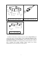
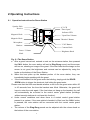
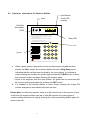
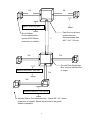
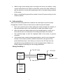
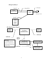
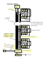
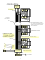
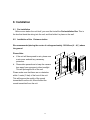
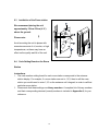
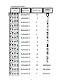
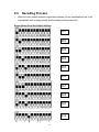
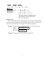
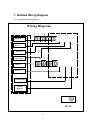
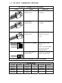
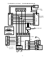
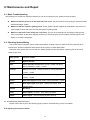
Anchor AN-3668 Video Intercom System User's and Installation Manual KP-800C/AN-3668/GS-001 Please read this manual carefully and save for future reference. Contents 1. 2. 3. 4. 5. 6. Introduction Operating Instructions 2 5 2.1 Instructions for the AN-3668 Room Station Operation 2.2 Instructions for the KP-800C Entrance Station Operation 5 6 Conduit Tubing 7 3.1 Conduit Tubing Layout 3.2 Conduit Tubing Tips 3.3 Pulling the Wires 7 7 Interface Wiring Other Wiring Installation 6.1 6.2 6.3 6.4 6.5 7. 8. 9 11 12 13 Pre-Installation Installation of the KP-800C Entrance Station Installation of the AN-3668 Room Station Code Setting Board on the AN-3668 Room Station Decoding Process Detailed Wiring Diagram Maintenance and Repair 8.1 Basic Troubleshooting 8.2 Checking System Wiring 8.3 Troubleshooting the AN-3668 Room Station 9. Specifications 18 21 21 21 22 23 9.1 AN-3668 Room Station Specifications 9.2 KP-800C Entrance Station Specifications 9.3 Power Supply Specifications 10. 13 13 14 14 16 Service Guarantee 23 23 23 24 1 1: Introduction Thank you for purchasing the Anchor Security System's AN-3668 Video Intercom system. We are sure that once you have started using it, you will find that it is a very convenient and reliable system, designed to make the process of protecting your home, business, or factory a little easier. Before we begin with the installation and setup instructions, we would like to explain the concepts behind each component of the system. The basic system consists of Entrance Stations, placed outside the entrance to a building or dwelling, and Room Stations, placed in the homes in a building or rooms in a dwelling. Ancho Fig. 1.1: The Room Station AN-3668 Room Stations have three main buttons, which are explained in the table below: Door Open Button: Triggers the electronic lock, to open the door, and let guests enter. Monitor Button: Turns on the monitor for surveillance of the entrance. Call Button: For communications with the Security Station The room station also includes a LCD monitor screen, a telephone handset, a speaker, a keypad, and various status lights. When a guest has arrived and entered the proper code number, the LCD screen will automatically come on, displaying the image transmitted from the entrance station, as well as making a Ding-Dong sound. If the host needs to speak with the guest, they simply have to pick up the telephone handset. If they decide to let the guest enter the 2 building, they simply have to press the DOOR OPEN button. The KP-800C Entrance Stations consist of a CCD camera, a microphone, a keypad, and an LED display. A guest coming to visit a building would simply enter the code number for the house he or she wants to visit and wait for the host to answer the call. IN U S E O p e r a tio n In s tr u c tio n 1 .K e y in re s id e n t‘ s d ig it c o d e a n d p re ss “ C a ll” . 2 .In t h e n e v e n t o f e rro r ,p re ss “ C le a r” a n d k e y in c o rre c t n u m b e rs. 3 .R e sid e e n t s m u st p re ss “ C a ll” b e fo re k e y in g in p e rs o n a l e n t ry a c c e ss c o d e . 4 .T o C a ll S e c u rity o r m a n a g e r p re ss “ S e c ” . 1 2 3 4 5 6 7 8 9 0 A B C C le a r C a ll Sec A nchor kp-800 There are also several accessories that are needed for installation of the system: the PW-104 Fig. 1.2: The Entrance Power Supply (one required for each entrance station in the system), the Video Signal Amplifier (used in systems with a large number of room station,), the Repeater (used to make the control signal stronger in systems with more than 100 units), and the Signal Control Connector Line (see Chapter 4: Interface Wiring),the PW-108 Power Supply (one required for 12 AN-668 room station). Output: 12VDC, AC Input Control 24VDC Control Signal AC Input Signal Input PW-104 Power Supply Output RP-100 Repeater 3 Direct Input Input by Resistance Blue Yellow Power Brown LED Video Output AC Power Fuse (6 ports) Input AN-VDA6 Video Signal Amplifier Control Signal Connector Line AC Power input DC Power output PW-108 Power Supply In addition to these items, a system may also contain a Guard Station and various other types of security options, such as Gas Leak Detectors, Door and Window Alarms, and Panic Buttons. The AN-3668 also has an optional Auto-Selector Controller, for selecting which of several cameras to connect with in systems with multiple cameras. Please contact your Anchor representative for more information on these options. 4 2:Operating Instructions 2.1 Operation Instructions for Room Station Speaker Hole 4" LCD "Door Open" Indicator LED Receive Magnetic Hook "Open Door" Button Magnetic Hook "Monitor" Button Microphone "Call" Button Handset Contrast Knob Power / Volume Knob Brightness Knob Fig. 2.1 The Room Station a. After a guest has arrived, entered a code on the entrance station, then pressed the CALL button, the room station will emit a Ding-Dong sound, and the screen will turn on, showing an image of the guest. If the host feels that the image on the screen is not good, the brightness and contrast can be adjusted by using the knobs on the bottom of the Room Station. b. When the host picks up the handset portion of the room station, they can immediately begin speaking with the guest. c. If the host wishes to let the guest enter the building, simply push the DOOR OPEN button to trigger the electronic lock letting the guest enter. Please note that the host must decide whether or not to let the guest enter within 30 to 40 seconds from the time the handset was lifted. Otherwise, the guest will have to enter the code again. If the host does not hang up the handset, the call will automatically be re-routed to the control center guard station (buildings without security stations do not have this function). d. Under normal conditions and when there is a central control guard station present in a system, if the room station's handset is lifted, and the CALL button is pressed, the room station will be connected with the control center guard station. c. The volume of the Ding-Dong sound can be adjusted with the volume knob on the bottom of the room station. 5 2.2 Operation Instructions for Entrance Station Host Station Code LED Display Lens Infra-Red Illumination LEDs IN U S E O p e r a tio n I n s tr u c tio n 1 .K e y in r e s id e n t ‘ s d ig it c o d e a n d p r e s s “ C a ll” . 2 .I n t h e n e v e n t o f e r r o r ,p re s s “ C le a r ” a n d k e y in c o r r e c t n u m b e rs . 3 .R e s id e e n t s m u s t p re s s “ C a ll” b e fo r e k e y in g in p e r s o n a l e n t r y a c c e s s c o d e . 4 .T o C a ll S e c u r it y o r m a n a g e r p r e s s “ S e c ” . 1 2 3 Busy LED 4 mic speaker A nchor 5 6 7 8 9 0 A B C C le a r C a ll Sec kp-800 a. When a guest enters a digit code into the entrance station keypad and then pushes the CALL button, the entrance station will emit a Ding-Dong sound, indicating that the call has been received by the room station. If a mistake is made entering the number, the guest simply pushes the CLEAR button to clear the incorrect number and begin entering the number again. If there is no response from the room station, the guest can be connected with the control center guard station by pressing the SEC button. b. If a resident of the building wishes to enter, simply entering the 4-digit PIN number assigned to that resident will open the door. Please Note: for efficiency reasons, there is an 80 second limit on the amount of time a call from the entrance station can last. If after 80 seconds, the guest wants to continue talking with the host, simply entering the code and pressing CALL again will place a new call. 6 3: Conduit Tubing 3.1 Conduit Tubing Layout Before any system can be installed or hooked up, the first step is to install conduit tubing to protect the wiring. This step should be at the same time the building is under construction, as it will be difficult to install the tubing once the building has been completed. Here are the basic guidelines for selecting and installing the tubing: a. b. The vertical extensions (to the individual room stations), must all have one 6C, one 3C/2V (RG58U), and one AC cable, so conduit tubing of appropriate diameter should be selected. The horizontal wiring should consist of the following: for less than 20 units for 20 ~ 60 units 60 ~ 150 units one 6C, one 3C/2V, and one AC one 6C, two 3C/2V, and one AC one 6C, three 3C/2V, and one AC We suggest using two separate conduits for the power and signal lines, however in some areas the placement of power lines is governed by certain regulations. Therefore, please check with local regulations before deciding on a final placement. 3.2 Conduit Tubing Tips a. While metal tubing of any kind is the most desirable material to Use for housing the wiring, PVC piping is also a suitable material. b. When selecting a location for the wiring, avoid running the wires parallel to power lines of any kind, as they may cause interference with the system. c. Avoid sharp bends in the conduit tubing. This will not only make it easier 7 3/4“ 3/4“ Approx. 30-40 cm from Room Station Pre-Installation Box . typical 90*60*40mm+ power box is suitable. Each floor must have a extension box. Recommended Size: 400 * 300 * 100 mm 1“ 3/4“ 3/4“ Ground Floor Distribution Box, must be 40x30x10cm or larger Distance from floor: 30-40cm 3/4“ 3/4“ Distance from floor: 120-140 cm Security Station Pre-Installation Box. Typical 90 * 60 * 40mm power box is suitable. Should be as close to the guard station as possible. 8 d. e. While using conduit tubing that is too large will cause no problem, using conduit tubing that is too small is a bad idea, as this will make it difficult to pull the wires up, as well as increasing the risk of insulation being rubbed off the wires. Keep in mind that the ground floor needs to have AC power wiring, for the entrance station. 3.3 Pulling the Wires After the conduit tubing has been installed, the next step is to pull the wires through the conduits. Here are some tips to make the process easier: a. Don't use excessive force when pulling the wires through the conduits. If the wires become stuck, use a lubricant to make them easier to pull. b. After the wires have been pulled up the horizontal(master) conduit, tie a c. d. knot with the wires, to keep them from falling back down the conduit. Use electrical tape to seal the exposed ends of the wires, to prevent corrosion. If the system has a central control guard station, and it is not connected directly to the entrance station (instead connected to the ground floor power distribution box), then there you must run two 9C lines from the ground floor power distribution box to the entrance station. Below is a simple diagram illustrating the two wiring possibilities: Wiring Possibility 1: Two 9C Lines Power Distribution Box 3C Lines Entrance Station Electronic Lock One 3C/2V Central Control Guard Station 9 Wiring Possibility 2: 3C Lines One 3C/2V One 9C Power Distribution Box Entrance Station Electronic Lock One 6C Central Control Guard Station Wire Specifications Diagram: Room Station Room Station Top Floor Distribution Box 3C/2V+8C 3C/2V+8C 3C/2V+ AC+8C Please Note: Ground Floor Distribution Box We suggest using wire diameter of at least 0.65mm Entrance Station or more for the control signal lines (6C or 9C). 3C/2V+9C 6C 10 Central Control Guard Station 4:Interface Wiring Terminator Box Brn./Yel./Blue Station 9 Insert Extra Final Room 5 6 7 8 10 11 12 Room Stations here Video Signal Resistance is usually 50 ~ 75 ohms. If the resistance in the system is not at this level, a resistor can be added here. 5 6 7 8 Room Station 9 1- Brown, 2- Red, 3Orange, 4- Yellow, 5- Green, 6- Blue 10 11 12 Video Line Inner Line(7) and Outer Line (8) 5 6 7 8 A Yellow PT Green 9 Entrance Station EL 10 11 12 Blue Lock Entrance Station Brown, Red, & Orange AC SOURCE Power Supply 11 Backpanel 4:Interface Wiring Terminator Box Final Room Station Brn./Yel./Blue 5 6 7 8 9 Insert Extra 10 11 12 Room Stations here Video Signal Resistance is usually 50 ~ 75 ohms. If the resistance in the system is not at this level, a resistor can be added here. 5 6 7 8 Room Station 9 5- Brown, 6- Red, 7- Orange, 8- Yellow, 9- Green, 10- Blue 10 11 12 Video Line Inner Line(7) and Outer Line (8) 5 6 7 8 A Yellow PT Green 9 Entrance Station EL 10 11 12 Blue Lock Entrance Station Brown, Red, & Orange AC SOURCE Power Supply 11 Backpanel 5: Other Wiring The Anchor AN-668 uses two different types of wiring: Single Core ( the 9C wire used in the main conduit) and Multi Core (the 3C/2V used for power supply in the system). At several points during the wiring process, wires are required to be spliced together. When splicing two wires of the same type, we recommend twisting the two wires together, at least 7 times, and then using electrical tape to insulate the splice. When splicing two different types of wire, however, we recommend twisting single core wire around the multi core wire, again, at least 7 times. Below is a diagram illustrating the two different methods for splicing wires. 12 6: Installation 6.1 Pre-installation Before room station the unit itself, you must first install the Pre-Installation Box. This is the box that feeds the wiring into the unit, and that holds it in place on the wall. 6.2 Installation of the Entrance station We recommended placing the center of unit approximately 120-140cm (4’ - 4½’) above the ground. Please Note: a. If the unit will be exposed to rain, please use a rain cover and add any necessary protection. b. Please take precautions to keep the camera lens away from exposure to direct sunlight. This will prolong the life of the unit. Please make sure that there are no obstacles within 1 meter (3 feet) of the front of the unit. This will improve the quality of the sound transmitted from the unit, this will affect the sound transmitted from the unit. 13 C F B A E D G 6.3 Installation of the Room station We recommend placing the unit approximately 120cm-150cm (4’-5’) above the ground. Please note: C Avoid mounting the unit in places with excessive amounts of oil, smoke, or high temperatures, as these may have an effect on the quality and life of the unit. 6.4 Code Setting Board on the Room Station Instructions 1. The code number setting board for each room station corresponds to the entrance station display. For example, if a room station was set to 1,2,3, then to call the room station you would need to enter 1,2,3 on the entrance unit’s keypad, in order to call that particular room station. 2. Please note that these settings use binary numbers. A complete list of binary numbers and their corresponding decimal (normal) numbers is included in Appendix A, for your reference. 14 Code Setting Procedure DIP Switch Position Number represented Hexadecimal 0+0+0+0= 0 0 1+0+0+0= 1 1 0+2+0+0= 2 2 1+2+0+0= 3 3 0+0+4+0= 4 4 1+0+4+0= 5 5 Symbol Displayed 0+2+4+0= 6 6 1+2+4+0= 7 7 0+0+0+8= 8 8 1+0+0+8= 9 9 0+2+0+8=10 A 1+2+0+8=11 B 0+0+4+8=12 C 1+0+4+8=13 D 0+2+4+8=14 E Not Used 1+2+4+8=15 F Not Used 15 Not Used 6.5 1. Decoding Process When the room station receives a signal that matches it’s own identification code, it will automatically emit a ringing sound, and the display will be powered on. Room Station Code Set Switch Settings 001 002 003 004 005 006 007 008 009 010 16 2nd Digit 1st Digit 3rd Digit 1 ON = 0 OFF = 1 2 ON = 0 OFF = 2 = 2 3 ON = 0 OFF = 2 * 2 = 4 4 ON = 0 OFF = 2 * 2 * 2 = 8 Using these 4 switches, it is possible to make any combination from 0(all 4 ON)to 15(all 4 OFF), or 16 combinations. Setting the Code On the Entrance Station, there is a digital display for the code. We recommend using the first digit to represent the address, the second and third digits for the floor. This will not only make it easy to remember each unit’s number, but also help with maintenance. Example 1: To represent the room station located at No. 1, 8th floor, use the code: 1 08 08 to represent the 8th 1 to represent No. Example 2: To represent No. 2, 9th floor, the code would be 2 09 17 7: Detailed Wiring Diagram 7.1 AN-3668 Detailed Wiring Diagram Wiring Diagram 5 6 7 8 BROWN RED ORANGE YELLOW 9 10 11 12 GREEN BLUE CONDUCTOR BIRAID SHIELD DC IN 18 7.2 KP-800C CONNECTOR EXPLAIN KP-800C CONNECTOR EXPLAIN FORM NAME EXPLAIN 9 PIN FEMALE CONNECTOR CONNECT TO ROOM STATION 6 PIN FEMALE CONNECTOR CONNECT TO GUARD STATION 6 PIN MALE CONNECTOR CONNECT TO PW-104 AND ELECTRONIC LOCK 4 PIN SELECT JUMPER SHORT: ONLY ONE KP-800 OPEN: TWO OR MORE KP-800 OR GUARD STATION EXIT 2 PIN VIDEO SELECT CONNECTOR CONNECT TO AS-001-1 (ONLY ONE KP-800) PS: The explain of connector are standard for connect on KP-800C. COLOR INDEX COLOR INDEX COLOR INDEX COLOR INDEX BROWN 1 GREEN 5 WHITE 9 RED 2 BLUE 6 BLACK 0 ORANGE 3 PURPLE 7 YELLOW 4 GREY 8 19 7.2 KP-800C CONNECTOR EXPLAIN KP-800C CONNECTOR EXPLAIN FORM NAME EXPLAIN 9 PIN FEMALE CONNECTOR CONNECT TO ROOM STATION 6 PIN FEMALE CONNECTOR CONNECT TO GUARD STATION 6 PIN MALE CONNECTOR CONNECT TO PW-104 AND ELECTRONIC LOCK 4 PIN SELECT JUMPER SHORT: ONLY ONE KP-800 OPEN: TWO OR MORE KP-800 OR GUARD STATION EXIT 2 PIN VIDEO SELECT CONNECTOR CONNECT TO AS-001-1 (ONLY ONE KP-800) PS: The explain of connector are standard for connect on KP-800C. COLOR INDEX COLOR INDEX COLOR INDEX COLOR INDEX BROWN 1 GREEN 5 WHITE 9 RED 2 BLUE 6 BLACK 0 ORANGE 3 PURPLE 7 YELLOW 4 GREY 8 19 7.3 KP-800C & AN-3668 STANDARD DIAGRAM + - PW-108 ENDING CONNECTOR 1 4 AC 220V/ 110V 6 COAXIAL CABLE (RG-58U) VDA DC JACK DC18V IN AN-3668 AN-3668 1 2 3 4 5 6 7 8 1 2 3 4 5 6 7 8 AC 220V/110V CABLE WIRE 0.65mm 1 2 3 4 5 6 8 9 9 PIN FEMALE CONNECTOR 110V 1 2 3 4 20 1 2 3 EL A PT ELECTRONI C LOCK 4 PIN SELECT JUMPER 1 2 3 4 5 6 PW-104 KP-800 6 PIN MALE CONNECTOR DC JACK DC15V IN AC 220V/ 6 PIN FEMALE CONNECTOR GS-001 1 2 3 4 5 6 1 2 3 4 5 6 7.3 KP-800C & AN-3668 STANDARD DIAGRAM + - PW-108 ENDING CONNECTOR 1 4 AC 220V/ 110V 6 COAXIAL CABLE (RG-58U) VDA DC JACK DC18V IN AN-3668 AN-3668 5 6 7 8 9 10 11 12 5 6 7 8 9 10 11 12 AC 220V/110V CABLE WIRE 0.65mm 1 2 3 4 5 6 8 9 9 PIN FEMALE CONNECTOR 110V 1 2 3 4 19 1 2 3 EL A PT ELECTRONI C LOCK 4 PIN SELECT JUMPER 1 2 3 4 5 6 PW-104 KP-800 6 PIN MALE CONNECTOR DC JACK DC15V IN AC 220V/ 6 PIN FEMALE CONNECTOR GS-001 1 2 3 4 5 6 1 2 3 4 5 6 8: Maintenance and Repair 8.1 Basic Troubleshooting The following is a checklist of simple procedures you can do to insure that your system functions properly. Make sure that the phone is on the hook when not in use. This should be a common thing to check first when trouble-shooting a system. Make sure that the system is getting power. As the system’s power supplies are all located in one place, it is quite simple to check and make sure that the system is getting power. Make sure that none of the wiring has come loose. This can be checked first by checking the wiring at the main circuit board, by the power supplies, and then by dismounting the entrance station and the suspect room station, to check the wiring their. 8.2 Checking System Wiring The Anchor Intercom System uses a compromised design, making it easy for repair or service personnel to do maintenance. All that is needed to find problems in the system is a basic Multi-meter. Each wire in the system has no more than two states. Please see the chart below, explaining the function and states of each wire: Wire (Color) Function / States Brown System Ground Red Voice and Video control wire. Normal: +9VDC and above; During Operation: +3VDC - +6VDC Orange Voice Line. Normal: +10VDC and above; During Operation: +1VDC - +4VDC Yellow Independent Control Line. Normal: 0VDC; During Operation: +2VDC - +5VDC Green Open Door Signal. Normal: 0VDC; During Operation: +5VDC Blue Door Open Light. Door Open: +20VDC and above; Door Closed: 0VDC Purple Not Used Gray Video Signal +. 0.2VAC - 1VAC during operation. White Video Signal -. Same as Brown(System Ground). 8.3 Troubleshooting the Room Station Please use the flow chart on the following page to perform troubleshooting on the room station: 8.4 Adjusting the Entrance Station 21 Please use the chart on page 25 for instructions on how to adjust the room station. Not Functioning? A. The Power switch is turned off. B. The power fuse is burned out. Does the C. The power to this area has been cut off. System have A. The DTR unit has failed. Is the system transmitting O B. The Microphone has failed. C. The handset wire is cut. D. The amplifier IC has failed. A. Room Station's code is incorrectly set. Does the room B. Volume setting is too low. station respond to a C. Decoding IC has failed. D. Sound IC has failed. NO Is the Display Does the LCD A. The LCD has failed. functioning ? brighten ? B. The control IC has failed. YES Does the LCD display an YES properly. 22 The Display wire is broken. The System should be functioning NO 9: Specifications 9.1 AN-3668S Room Station Power Source: DC +20V, 1 AMP. Power Consumption: Less Than 10 Watts Video Input: 1Vp-p NTSC/PAL (Factory Set) Audio Output: 0.5 Watt Time Use Limit: Approx. 60 seconds (+/- 10 seconds) Trigger Signal: Negative signal Resolution: More than 450 TV Lines Display: 4" Color TFT LCD Door Bell Sound: Ding-Dong Sound Max. Wiring Distance: 50 Meters / 0.65mm wire Max. No. Of Extra Units: 2 Units Interface: 4 Wire Polarized Dimensions: 60mm ( D ) x 200mm ( W ) x 235mm( L ) Weight: Approx. 1200 g 9.2 KP-800C Entrance Station Specifications Power Source: +12VDC and +24VDC Power Consumption: 6 Watts Maximum Video Output: 1 V.P.P. EIA/CCIR (Factory Set) Audio Input 0.5 watt - 1 watt Resolution: 25 million pixels Min. Illumination: 0.2 Lux (0 Lux with infra-red LED option) Camera: 1/3” B/W CCD Operating temperature: Max. wiring distance: Dimensions: -10 to 55 500M 300mm (H) x 225mm (W) x 65mm (D) 11.81in (H) x 8.86in (W) x 2.56in (D) Weight: 2700g (5.94 lbs.) 9.3 PW-104 Power Supply Power Supply: 110VAC/5A or 220VAC / 5A (Factory set) Power Output: 110VAC/5A or 220VAC/5A (Factory set), 12VDC/1.6A, and 24VDC/1A Dimensions: 150mm (Height) x 110mm (Width) x 35mm (Depth) 6in (Height) x 4.3in(Width) x 1.4in (Depth) Weight: 2250g (4.95 lbs.) 23 9-4 AD-020 Power Supply Power Source: Power Output: Dimensions: Weight: AC 110V or 220V (Factory Set) DC +20V, 1 AMP. 85mm(L) x 68mm(W) x 56mm(D) Approx. 650 g 10: Service Guarantee The products described in this manual come with a 1-year guarantee. Starting from the delivery date, the owner of this product is entitled to free repair and service of the unit, except in cases such as disaster, accident, willful destruction by the owner or other people, improper use (such as placing the unit in an area exposed to rain, but not installing proper protection for the unit). After the end of this period, service is offered at rates dependent on the condition of the unit. Manufacturer: Anchor Security Systems Co., Ltd. 4th Floor - 1, No. 70, Chien Liu Rd. Chung Ho, Taipei Hsien, Taiwan Tel: 886 (2) 22256651 (6 lines) Fax: 886 (2) 22256653 National Representative: Area Representative:


![Manual [formato PDF - 0MB]](http://vs1.manualzilla.com/store/data/006096635_1-ee7d2aa01bf1f6a6ab4acf12f7040803-150x150.png)