1
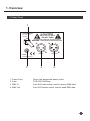
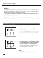
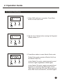
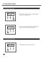
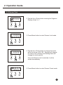
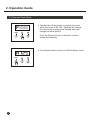
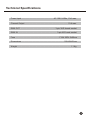
American DJ
R
Uni pack
USER'S MANUAL
Please read before use
English
Contents
Features 1
General Instructions 2
1. Overview 3
1.1 Front Panel 3
1.2 Rear Panel 4
2. Operation Guide 5
2.1 DMX Address Mode 5
2.2 Switch Pack Mode 6
2.3 Dimmer Pack Mode 7
Technical Specifications 10
American DJ
R
Uni pack
Improvement and changes to
this manual, specifications
and design, may be made at
any time without prior notice.
ALL RIGHTS RESERVED.
American DJ
Los Angeles, CA 90058 USA
R
Features
Thank you for purchasing this American DJ product.
This Unit Pack features include:
3-pin standard DMX IN/OUT ports providing dimmer information
Serves as a Switch Pack or Dimmer Pack, depending upon
the current operating mode.
Allows DMX Addressing, Dimmer Preset and Dimmer Limit.
Power failure memory.
4 digits Segment Display shows current activity
and function state.
Every effort has been made to design dependability, reliability and
comfort into each unit. New products are being designed constantly
to meet the needs of both entertainment and the lighting industry.
We welcome your comments about our product and services.
It is both a privilege and a pleasure serving you.
1
General Instructions
Please read through this operating instructions before installing or using
your new product. After you have finished reading the instructions, put
them away in a safe place for future reference.
Safe and Efficient Use
This product must be earthed.
Do not make any inflammable liquids, water or metal objects
enter the unit.
Take care not to damage the power cord.
No user serviceable parts inside, always consult authorized
personnel for repairs.
In the event of a malfunction(burning smell, etc.), immediately
stop operation, disconnect the power supply plug, and consult
authorized service personnel.
To prevent fire or shock hazard, do not expose this product to
rain or moisture.
Product Care
This product is intended for indoor use only.
Provide occasional ventilation during use.
Unplug the power plug from the sockets when not using the
unit for extended period.
Do not use the unit in places subject to excessive humidity,
vibration or bumps.
Place this unit in a stable location.
Do not dismantle or modify the unit.
2
1. Overview
1.1 Front Panel
OUTPUT: 10A Max.
1
A =DMX ADDRESS
D/S=DIM/SWITCH
DMX
P = DIM PRESET
L =DIM LIMIT
.8:8:8:8
2
5
MENU
3
American DJ
4
R
Uni pack
1. Output:
2. Segment Display:
3. Menu button:
4. Up button:
5. Down button:
3
6 A max.
Shows current activity or function state.
Press to enter next level.
Each tap will increase the value once.
Pressing and holding down will increase quickly.
Each tap will decrease the value once.
Pressing and holding down will decrease quickly.
1. Overview
1.2 Rear Panel
1
POWER INPUT:
AC 120V~ 60Hz
10A MAX
CAUTION
RISK OF ELECTRIC SHOCK
DO NOT OPEN
N'OUVREZ PAS..RISQUE DE CHOCELECTRIQUE
WARNING: THIS APPARATUS MUST BE EARTHED
FUSE:
DMX IN
DMX OUT
F10A 250V 5x20mm
2
1. Power Cord:
2. Fuse:
3. DMX In
4. DMX Out
3
4
Plug in the appropriate power outlet.
F10A 250V 5x20mm
3-pin XLR male socket, used to receive DMX data.
3-pin XLR female socket, used to send DMX data.
4
2. Operation Guide
General
Plug in the appropriate power outlet, this unit recovers to the function state of
last time automatically by reasons of power failure memory, and the Segment
Display shows the DMX address of last change.
If the frequency of power is not stable, the Segment Display will show "AC-0",
wait until the power is stable.
The UP-1 serves as a dimmer pack or a switch pack, depending on operating
mode you've selected.
2.1 DMX Address Mode
.8:8:8:8
MENU
.8:8:8:8
1. The Segment Display shows the DMX address
of last change when powered this unit.
If you've selected DMX address 123 for the last
time, then the Segment Display will read 123.
2. Each tap of the Up or Down button will change
the DMX address once. Pressing and holding
down will change the DMX address quickly.
MENU
Once the DMX address is selected, it will be
stored into memory automatically.
NOTE:
During DMX addressing, output is disabled.
5
2. Operation Guide
2.2 Switch Pack Mode
.8:8:8:8
---
1. When DMX address is complete, Press Menu
button to enter next level.
MENU
.8:8:8:8
s ---
2. Tap the Up or Down button causing the Segment
Display shows "s---".
MENU
3. Press Menu button to enter Switch Pack mode.
.8:8:8:8
Switch Pack mode consists of Switch On(S-on)
and Switch Off(S-of).
MENU
In the Switch On mode, output is turned on and
the fixture lights regardless of DMX signal.
In the Switch Off mode, output is turned off and
the fixture is controlled by DMX signal. When
DMX level is less than 40%, the fixture goes out;
when DMX level exceeds 40%, the fixture lights.
6
2. Operation Guide
2.2 Switch Pack Mode
.8:8:8:8
4. Tap the Up or Down button to change between
Switch On and Switch Off.
MENU
5. Once the Switch Pack is selected, press Menu
button to return to DMX Address mode.
MENU
2.3 Dimmer Pack Mode
1. Press Menu button to enter next level.
MENU
7
2. Operation Guide
2.3 Dimmer Pack
.8:8:8:8
---
2. Tap the Up or Down button causing the Segment
Display shows "d---".
MENU
3. Press Menu button to enter Dimmer Limit mode.
MENU
MENU
4. Tap the Up or Down button to change the value
within the range of 30-100. Each tap will change
the value once, pressing and holding down will
change the value quickly.
Once the Dimmer Limit is selected, it will be
stored automatically.
5. Press Menu button to enter Dimmer Preset mode.
MENU
8
2. Operation Guide
2.3 Dimmer Pack Mode
MENU
4. Tap the Up or Down button to change the value
within the range of 00-100. Each tap will change
the value once, pressing and holding down will
change the value quickly.
Once the Dimmer Preset is selected, it will be
stored automatically.
5. Press Menu button to return to DMX Address mode.
MENU
9
Technical Specifications
Power Input ........................................................... AC 120V~60Hz, 10 A max.
Channel Output ................................................................................ 10 A max.
DMX OUT ................................................................ 3-pin XLR female socket
DMX IN ....................................................................... 3-pin XLR male socket
Fuse ................................................................................. F10A 250V 5x20mm
Dimensions ............................................................................... 182x92x65mm
Weight ................................................................................................... 1.1 Kg
10
ALL RIGHTS RESERVED
Rev 1.0 Jun., 2000
American DJ
R
24-004-0348