1
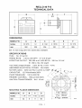
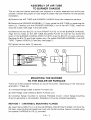
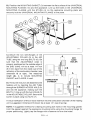
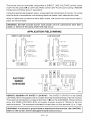
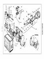
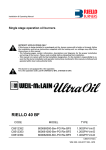
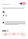
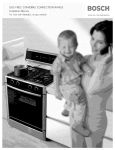
BURNERS
MODEL F10
INSTALLATION
MANUAL
RIELLO 40
SERIES
OIL BURNERS
RETROFIT APPLICATIONS
NON-RETROFIT
If this
burner
boiler
or furnace),
the heating
F10-2000-02
is being
unit,
installed
follow
as settings
APPLICATIONS
in a packaged
the installation
may differ
ONLY
unit (ie. burner
and set-up
instructions
from
shown
those
comes
in this
with
supplied
a
with
manual.
2902554-1
TABLE
OF CONTENTS
TECHNICAL
DATA ...........................................
Dimensions
...........................................
1
1
Specifications
.........................................
OIL BURNER COMPONENTS
IDENTIFICATION
1
2
....................
F10 Burner Components
.................................
Serial Number Identification
..............................
INITIAL
SET-UP
ASSEMBLY
MOUNTING
.............................................
OF AIR TUBE
THE BURNER
Method
2
TO BURNER CHASSIS ...................
TO BOILER OR FURNACE
...............
1- Universal
Mounting
Flange
3
APPLICATION
FIELD WIRING ..................................
NOZZLE PLACEMENT
........................................
6
7
OF DRAWER
ASSEMBLY
...................
7
SETTING
.......................................
SETTING
......................................
OIL LINE CONNECTIONS
Single
8
8
.....................................
8
Feed System)
9
Line (Gravity
.........................
Two Line (Lift System)
..................................
PURGE ..............................................
10
11
Single
.........................
11
Two Line (Lift System)
..................................
SETTING THE AIR ADJUSTMENT
PLATE .........................
11
12
BURNER SET-UP CHART .....................................
SPARE PARTS ..............................................
12
14
PRECAUTIONS
PRECAUTIONS
16
17
PUMP
Line (Gravity
Feed System)
- CANADA .....................................
- U.S.A ........................................
PARTS
Your
Riello
sure
all parts
QTY.
42-
.......................
5
5
5
ELECTRODE
TURBULATOR
_
3
3
Method 2- Semi-flange
Collar .............................
Method 3- Pedestal Mount
...............................
ELECTRICAL
CONNECTIONS
..................................
INSERTION/REMOVAL
2-
2
2
40 F10 burner
are present
DESCRIPTION
should
before
include
LIST
the following
beginning
(parts bag)
Mounting
flange bolts (short)
Semi-flange
bolts (long)
Nuts
Chrome
nuts
check
QTY.
DESCRIPTION
(carton)
1 -
Burner
with
1 -
Universal
Semi-flanges
Mounting
gasket
Installation
Manual
By-pass
11-
Oil pump
connector
(supply)
Oil pump
connector
(return)
1 -
21-
Female 1/4" NPT adapter
Male 3/8" NPT adapter
shipped
Please
the installation.
2 1 1 -
* OEM burners
parts.
chassis
Mounting
plug
1 -
2.5 mm Allen key
(separate
carton)
1 Combustion
head
with combustion
F10 -I
head mounted.
cover
Flange
to make
RIELLO 40 F10
TECHNICAL DATA
!_
B
O
L)
D6012
DIMENSIONS
Inches
10 5/16
12
8 1/32
3 15/16
5
10 7/16
262
305
204
100
127
265
mm
El
10 inch long
(254 mm)
tubes
also
available.
SPECIFICATIONS
FUEL:
No. 2 Fuel
FIRING
RATE:
EFFECTIVE
Oil
1.45 to 2.95
OUTPUT:
GPH
203,000
51,160
VOLTAGE
(Single
ABSORBED
MOTOR
ELECTRICAL
(rated):
CAPACITOR:
PUMP
Phase):
120V
kcal/h
60Hz(+10%
-15%)
264 Watts
Run Current
2.2 AMP
130 to 200PSI
CONTROL:
IGNITION
TRANSFORMER:
MOUNTING
F10
RIELLO530SE/C
FLANGE
I
mm
to 104,130
59.5 to 121 kW
12.5Microfarads260V
PRIMARY
Inches
to 413,000BTU/h
POWER:
3250rpm
PRESSURE:
MODEL
4.7 to 9.5kg/h
8kV
16mA
DIMENSIONS
I
5 1/2"-
A
B
1 1/4
1/4
7/16
2 3/16
32
6
11
56
FIO-
7 1/2" - 190 mm
8 15/32"
1
- 215 mm
D6000
OIL BURNER COMPONENTS IDENTIFICATION
RIELLO 40 SERIES
F10
BURNER
COMPONENTS
1. Lockout indicator
Reset button
2. Primary
control
3. Primary
control
9.
lamp and
End cone
10. Turbulator
adjustment
11. Air tube cover
12. Coil
sub-base
4. Pump pressure regulator
adjustment
screw
5. Motor
13. Vacuum
15. Return
fuel line port
6. Capacitor
16. Supply
fuel line port
7. Air adjustment
8. Air shutter
SERIAL
fixing
NUMBER
screw
gauge
14. Pressure
gauge
17. Adjustable
screws
18. Mounting
connection
port
and bleeder
port
collar
flange
with gasket
IDENTIFICATION
The Riello 15 character
serial number, example,
97 A 8511111
00025, is identified as
follows:
97 = last two digits of the year of manufacture;
A = BI-week of manufacture;
8511111 = burner product code;
00025 = increment
of 1 for each burner produced - specific to product code - reset to zero each January 1st.
iYea r of Manufacture
_
97)_(A)(
I Bl-week
851111)_
of manufacture
INITIAL
A) Remove burner and air tube from
all parts are present.
I burner
cartons.
Check
the three
C) Remove
drawer
assembly
from
adjustment
for specific
input required
air tube,
(see pages
Mount
air tube to burner
chassis
(see
Sequence]
product
code I
SET-UP
B) Remove
burner cover by loosening
box and air tube cover (see page 7).
D)
( 00025 _
page
F10-
2
parts
screws
3).
list (inside
securing
cover)
to ensure
it. Remove
insert
nozzle
and set
7 & 8), then set aside.
control
turbulator
ASSEMBLY OF AIR TUBE
TO BURNER CHASSIS
The air tube and drawer assembly
are shipped
in a carton separate
chassis. Choose the proper air tube length to obtain the tube insertion
installation.
A) Remove
the AIR
TUBE
and
BURNER
CHASSIS
from
their
from the burner
for the specific
respective
cartons.
B) Remove the DRAWER
ASSEMBLY
(1) from inside the AIR TUBE by loosening
screw (2). Carefully
pull the DRAWER
ASSEMBLY
out of the AIR TUBE, instal
required
nozzle (see page 7) and set aside.
C) Remove
Align
open
the two
BOLTS
(3) from
the two holes on the AIR
on the BURNER
CHASSIS
FRONT
PLATE
(4) of the BURNER
TUBE HOLDING
PLATE
(5) with the two
FRONT PLATE when the BOLTS (3) were
Replace the BOLTS and finger tighten only. Re-install
TUBE. Tighten
SCREW (2) securely
(see page 7).
D) Tighten
the two bolts
DRAWER
ASSEMBLY
the
the
CHASSIS.
holes left
removed.
into AIR
(3) securely.
t
$7462
MOUNTING THE BURNER
TO THE BOILER OR FURNACE
There are three possible
application.
These are:
1) Universal
2)
flange
Semi-flange
collar
methods
bolted
to mount
to Boiler/Furnace
bolted
the
burner,
1 - UNIVERSAL
to Boiler/Furnace
MOUNTING
unit.
mount,
where flange-mounting
be ordered
separately.
FLANGE
A) Insert the two BOLTS (1) into the UNIVERSAL
MOUNTING
flat side, ensuring the bolt heads are flush with the flat surface.
two special
CHROME
NUTS
(2) provided.
F10-
on the individual
unit.
3) Universal
flange
mounted
to optional
Pedestal
direct to appliance
is not possible.
Pedestal
kit must
METHOD
depending
3
FLANGE (10) from the
Secure in place using
B) Position the MOUNTING GASKET (3) between the flat surface of the UNIVERSAL
MOUNTING FLANGE (10) and the appliance. Line up the holes in the UNIVERSAL
MOUNTING FLANGE with the STUDS (4) on the appliance mounting plate and
securely bolt the UNIVERSAL MOUNTING FLANGE to the plate.
$7461
C) Secure
the
two
ADJUSTABLE
semi-flanges
COLLAR
of the
(9) to the
AIR
DRY
BASE
BOILER
TUBE using the two long BOLTS (6). Be
sure that the ADJUSTABLE
collar
is
properly positioned so the outside edge of
the END CONE will be at least 1/4 inch
(6.5 mm) back from the inside wall of the
refractory
of the combustion
dimension
B
at
right).
chamber
The
iJ
(see
A
measured
D6013
length
(A), is to include
MOUNTING
GASKET and FLANGE, if used.
D) The burner
may now be attached
heating
unit by inserting
through
the BURNER
and
into the
the
AIR
ACCESS
appliance,
COMBUSTION
CHAMBER
to the
TUBE
HOLE (8)
making
sure
the
E::Z:Z:Z:Z:_
j .............
BOLTS (1)line up with the two HOLES (5)
in the ADJUSTABLE
COLLAR. Secure the
burner
in place
A visual
using two NUTS (7).
verification
of the air tube insertion
unit is suggested.
NOTE:
Hold
proper
D6014
Dimension
A suggested
the gasket
positioning.
method
against
Lightly
B should
into the combustion
be at least
for creating
mounting
the appliance
mounting
tap the flange
with
F10-
of the heating
1/4" (see drawing).
bolt holes
bolts
a hammer
4
chamber
using
in the mounting
the
to form
mounting
the holes.
gasket:
flange
for
METHOD
2 - SEMI-FLANGE
A)
item
Follow
C from
COLLAR
METHOD
1.
B) Align the air tube and attached
adjustable
collar so air tube is centered
burner access hole of the boiler/furnace
unit. Mark the center of the two holes
ADJUSTABLE
COLLAR
(6.5 mm) holes through
on to the front plate of the heating
unit. Then drill
the front plate of the unit, using marks as a guide.
C) Install two short BOLTS
(1) through
inside, and secure on the outside using
D) Follow
item
METHOD
Secure
D from
METHOD
3 - PEDESTAL
the
MOUNTING
installing
brackets
WARNING:
to
Secure
that
over
the front plate of the heating
unit from
the two special CHROME
NUTS (2).
the
1.
FLANGE
It is suggested
1/4 inch
MOUNT
provided with the pedestal.
items A, C and D.
NOTE:
in the
in the
the
MOUNTING
PEDESTAL
burner
to MOUNTING
pedestal
be anchored
the pedestal
tube
WHEN THE COMBUSTION
and securing
CHAMBER
using
FLANGE
hardware
as in METHOD
in position
brackets
the
on the
floor
1,
by
to the floor.
IS LINED WITH A REFRACTORY
MATERIAL,
IT IS IMPERATIVE
THAT THE END CONE NOT PROTRUDE
INTO THE
CHAMBER
AREA, AS EXCESSIVE
HEAT AT BURNER SHUT-DOWN WILL DAMAGE
THE END CONE.
ELECTRICAL
It is advisable
to leave the control
connections
to the burner.
1) Wire access hole
(Use BX electrical
CONNECTIONS
box off the sub-base
connector)
2)
Earth ground conductor
(GREEN WIRE)
3)
Hot conductor terminal
(BLACK WIRE)
4)
Neutral conductor
(WHITE WIRE)
terminal
terminal
5) Strain relief clamp
WARNING:
The hot (black) wire
must be connected
to the L terminal
and
the neutral
wire must be connected
terminal
or
the
primary
(white)
to the N
safety
$7454
control will be damaged.
Do not connect either wire to the
(_Terminal.
F10-
5
while
completing
the electrical
The burner may be controlled using either a DIRECT LINE VOLTAGE control circuit
(120V AC 60 cycle) OR a LOW VOLTAGE control (24V AC 60 cycle) using a R8038A
Honeywell switching relay or equivalent.
Using the appropriate diagram below, make electrical connections to burner. All wiring
must be done in accordance with existing electrical codes, both national and local.
When all electrical connections have been made, the control box may be put back in
place on the sub-base.
I WARNING:
made, or failure
DO NOT
of the
activate
pump shaft
burner seal
untilmay
proper
occur.oil line connections
APPLICATION
W
LOW VOLTAGE
Eli FUSE 15A
I
_ O ,/LINE
o/
FUSE
15A
o/
SAFETY
SWITCH
LINE SAFETY
_
F
_---_'f
_1
_-_,_ /
OPERATING
ZC_
_
_,%6/
_1
__O/
UMiTSwITCH
OD
_"
__f
LiMIT SWiTCH
-r
1..-
_
z
S _)/
::z:/
SAFETY
LIMIT SWITCH
t
<
uJ
SwiTCH
OPERATING
] ?WITCHING
/
il
been
FIELD WIRING
DIRECT LINE VOLTAGE
I
have
RELAY
SAFTET_wiTCH
FACTORY
WIRED
SUB-BASE
z
2
DI
VAL
K
_1
CAP
OR
D5995
REMOTE
SENSING
OF SAFETY
LOCKOUT:
The SAFETY
SWITCH
in the
530SE
CONTROL
BOX is equipped
with a contact allowing
remote sensing of burner lockout.
The electrical
connection
is made at terminal
4 (O) on the SUB-BASE.
Should lockout
occur the 530SE CONTROL
BOX will supply a power source of 120Vac to the connection
terminal.
The maximum
allowable
current
draw
on this terminal
I WARNING:
BOX on the Ifburner
a neutral
will orbeground
damaged
lead should
is attached
lockout
to this
occur.
terminal,
F10-
6
(4) is 1 Amp.
the CONTROL
NOZZLE
A) Determine
for the boiler
ering
the
PLACEMENT
the proper
firing rate
or furnace
unit, consid-
specific
application,
then
use the Burner Set-up chart on page
12 to select
the proper
nozzle
and
pump pressure
to obtain
input from the burner.
the required
B) Remove
the NOZZLE
ADAPTER
(2) from the DRAWER ASSEMBLY
by
loosening
the SCREW
(1).
C) Insert the proper
NOZZLE ADAPTER
D) Replace
screw (1).
S7459
NOZZLE
into the
and tighten securely
adapter,
with
nozzle
(Do not overtighten).
installed,
INSERTION/REMOVAL
A)
To remove
by carefully
drawer
pulling
B) Remove
the
SCREWS
(4).
C) Loosen
combustion
assembly,
AIR
TUBE
D) To insert drawer
assembly,
attach fuel line to the pump.
SCREW
and secure
with
ASSEMBLY
(3), then unplug
CONTROL
BOX
1)
up.
COVER
SCREW
(2), then
head as shown.
assembly
OF DRAWER
loosen
it back and then
into drawer
slide
reverse
PLATE
the
the
(5)
by
complete
procedure
loosening
drawer
the
assembly
in items
two
retaining
out
A to C above,
of
the
then
$7460
F10-
7
ELECTRODE
SETTING
IMPORTANT:
THESE DIMENSIONS
MUST BE OBSERVED
AND VERIFIED.
5/32" or 4 mm
tt_
5/32"
to 13/64"
or 4 to 5_
....................
D6003
-I--
TURBULATOR
A) Loosen
SETTING
NUT (1), then turn SCREW
(2) until the INDEX MARKER
(3) is
aligned with the correct index number
as per the
page 12.
Burner
B) Retighten
NOTE:
Set-up
chart,
the RETAINING
on
NUT (1).
Zero and five are scale
5111111
indica-
tors only. From left to right, the first line
is 5 and the last line 0.
OIL LINE CONNECTIONS
This burner
To operate
is shipped with the oil pump set to operate
on a single line system.
on a two line system the by-pass plug must be installed.
Warning:
Do
Operating
a single
to the pump
not
shaft
operate
a single
line system
with
line
the
system
by-pass
with
plug
the
installed
by-pass
will
plug
result
installed.
in damage
seal.
Note:
Pump pressure
must be set at time of burner start-up.
A pressure
gauge is
attached
to the
PRESSURE
PORT
(8)
for
pressure
readings.
Two
PIPE
CONNECTORS
(5) are supplied
with
the burner
for connection
to either
a single
or a
two-pipe
oil lines
system. Also supplied are two ADAPTORS
(3), two female 1/4" NPT, to adapt
to burner pipe connectors.
All pump port threads are British
Parallel
Thread
design.
Direct
connection
of NPT threads
to the pump
F10-
8
will
damage
the pump
body.
Riello manometers and vacuum gauges do not require any adaptors, and can be safely
connected to the pump ports. An NPT (metric) adapter must be used when connecting
other gauge models.
D6179
SINGLE
LINE
(GRAVITY
FEED
SYSTEM)
A) The burner is shipped configured for use in single line applications.
the oil pump are required for use in single line applications.
No changes
to
NOTE: If the pump cover (1) is removed for any reason, be sure the O-ring (2), is properly
seated in the pump cover (1) before re-attaching the pump cover to the pump housing.
SINGLE
LINE SYSTEM
H
3/8"
- PIPE LENGTHS
OD
1/2"
OD
FT
M
FT
M
FT
M
1.5
0.5
33
10
65
20
3.0
1.0
65
20
130
40
5.0
1.5
130
40
260
80
6.5
2.0
195
60
325
100
D6009
"1"-
/
NOTE:
Do not exceed pipe lengths
indicated in chart.
B) Connect the pipe connector to the SUPPLY PORT (6) of the pump. Attach the required
piping to this pipe connector.
Be sure that the plug in the RETURN PORT (9) is tightened
securely.
F10-
9
TWO LINE (LIFT SYSTEM)
n
4
D6008
-I-
2 LINE (LIFT)
SYSTEM
H
3/8"
plug
with
If a two line system
is required,
install
OD
1/2" OD
FT
M
FT I
M
_T
0.0
0.0
1151
35
3301
100
1.5
0.5
1oo I
30
3301
100
3.0
1.0
80
I
25
3301
100
5.0
1.5
65
I
20
2951
90
6.5
2.0
50
I
15
2301
70
9.5
3.0
25
I
8
1001
30
11
3.5
20
I
6
65
NOTE:
A)
- PIPE LENGTHS
I
I
M
20
Do not exceed pipe lengths
indicated in chart.
the By-pass
plug (4) provided.
The by-pass
is installed
in the return port (9) of the pump. A 2.5 mm hexagonal
key provided
the by pass plug is to be used to install the plug. DO NOT use an inch size
hexagonal
key, damage to the by-pass plug may result. When operating
on a two line
system, supply and return lines should be the same diameter
and both should extend
to the same
in the piping
depth inside
system.
Any obstructions
exceed the pipe
To install
the by-pass
1) Remove
2) Install
in the
lengths
the return
the by-pass
the fuel
tank.
Be sure there
return line will cause failure
indicated
in the tables.
are no air leaks
of the
pump
shaft
or blockages
seal.
Do not
plug:
plug
(9).
plug
(4) using
the 2.5 mm hexagonal
key.
B) Attach the two PIPE CONNECTORS
(5) to the pump SUPPLY
and pump
PORTS (6 and 9). Attach the required
piping to these two pipe connectors
NPT/METRIC
ADAPTERS
that are supplied
with the burner.
nection to the
fueldope
pump.
I WARNING:
Pipe
orTeflon
RETURN
using the
tape are NOT to be used on any direct oil con-
exceed 13 feet
m).
I WARNING:
The(4 height
"P" in Pipe Length charts on page 9 and 10 should not
I WARNING:
The vacuum
should
not exceed
11.44 inches of mercury.
in the fuel
betweenappropriately
the fuel tank listed
and the
pump.
I placed
IMPORTANT:
An line
external,
andburner
certified
oil filter
F10-
10
must be
PUMP PURGE
NOTE: to protect
system.
A)
the pump gears,
Apply oil through
SINGLE
LINE
it is advisable
the VACUUM
(GRAVITY
PORT
FEED
to lubricate
the pump prior to purging
a lift
(C).
SYSTEM)
A) Loosen the bleeder valve (A) until oil flows out. Tighten the bleeder valve securely and
start burner.
B) When bleeding
1) Loosen
the bleeder
2) Disconnect
nozzle
the pump by pressure.
nozzle
oil supply
line at the pump
port (B).
3) Attach a flexible
plastic tube to the pump noz-
zle port, directing
4) Loosen
valve (A).
the screws
er, allowing
the oil flow into a bucket.
securing
it to be removed
5) Holding the air tube cover
tion start the burner.
6) When the solenoid
the air tube covfreely.
in its proper
valve is engaged,
loca-
approx-
imately 10 seconds after starting, remove the
air tube cover and shine a light source on the
photo-cell, allowing it to see false light.
7) Run the burner until the fuel pump has been
purged of air, then tighten the bleeder valve
and immediately
8) Reinstall
shut
down
the burner.
the air tube
cover
and nozzle
9) The burner
can now be started
D6177
line.
normally.
WARNING:
Omitting steps 2 and 3 will result in a collection of unburned
bustion chamber creating a hazardous
situation upon burner startup.
oil in the com-
B) TWO LINE (LIFT SYSTEM)
Turn off the main power source to the burner and remove the air tube cover. Shine a light
source on the photo-cell (now visible where the air tube cover was removed), return power
to the burner and activate the burner. With the light source in place, the burner will operate
in prepurge only. Once the burner is purged, turn off the power source and replace the air
tube cover. Return power to the burner. The burner is now ready to operate.
ATTENTION: It is important that the fuel line be completely sealed and free from air
leaks or any internal blockages,
IMPORTANT!
WHEN THE BY-PASS PLUG IS INSTALLED, A TWO PIPE SYSTEM
MUST BE USED OR FAILURE OFTHE PUMP SHAFT SEALWILL OCCUR.
F10-
11
SETTING THE AIR ADJUSTMENT
A) Regulation
ADJUSTMENT
of the combustion
PLATE
(1) after
setting
Burner
air adjustment
Chart.
B)
of the
Set-up
The proper
number
air flow
loosening
plate
should
on the manual
PLATE
is made by adjustment
the FIXING SCREWS
be made
according
of the manual AIR
(2 &3).The
initial
to Column
5 in the
AIR
ADJUSTMENT
PLATE (1) should line up
with the SETTING
INDICATOR
(4) on the
fan housing cover. Once set, the air adjustment
plate should be secured in place
by tightening
SCREWS
C) The final position
plate will vary on each
struments
to establish
for maximum
zero.
NOTE:
2 and 3.
of the air adjustment
installation.
the proper
CO 2 and a smoke
Variations
in flue
Use insettings
reading
gas,
®
of
smoke,
CO 2 and
temperature
readings
may be
experienced
when the burner cover is put
in place.
Therefore,
the burner
cover
must
be in place when making the final
combustion
ensure proper
instrument
test results.
readings,
D5231
to
BURNER SET-UP CHART
ACTUAL FIRING
RATE + 5%
NOZZLE
SIZE
PUMP
PRESSURE
TURBULATOR
SETTING
AIR DAMPER
SETTING
GPH
kg/h
GPH
PSI
BAR
1.45
4.7
1.25 x 60 °
145
10
1.5
2.7
1.80
5.8
1.50 x 60 °
145
10
2.0
2.8
2.10
6.8
1.75 x 60 °
145
10
2.5
3.1
2.40
7.8
2.00 x 60 °
145
10
3.5
3.4
2.75
8.9
2.25 x 60 °
150
10.4
4.0
4.2
2.95
9.5
2.50 x 60 °
140
9.8
4.5
4.2
NOZZLES:
Monarch
R-PLP,
DelavanW-B,
DanfossS-B,
NOTE:
A 60 ° degree
nozzle is suggested,
however,
used in cases where the flame is unstable
at light-off
temperatures.
F10-
12
SteinenSS-S,
a 80 ° degree
when operated
HagoP.
nozzle
may be
at low ambient
COMBUSTION
CHAMBER
Follow the instructions furnished by the boiler/furnace
manufacturer.
Size retrofit
application according to the appropriate installation codes (eg. CSA B139 or NFPA #31 ).
NON-RETROFIT
If this
burner
furnace),
as settings
APPLICATIONS
is being
follow
installed
the installation
will differ
from
those
in a packaged
and set-up
shown
unit (ie. burner
instructions
in this manual.
F10-
13
supplied
comes
with
with
a boiler
the heating
or
unit,
12
11
18
29
26
10
47
\
\
20
21
22
-I1
m
I
OPTIONAL
33
32
SPARE PARTS LIST
NO.
CODE
DESCRIPTION
NO.
CODE
DESCRIPTION
1
3007234
Burner Back Cover
33
3007205
Manual Air Shutter
2
3006992
Pipe connector
- Supply
34
3007209
Air Intake Housing
3
3006571
3/8" NPT/Metric
Adapter
4
3006993
Pipe connector-
Return
5
3005847
3949071
3006978
Short Combustion
Turbulator Disc
6
3007077
1/4" NPT/Metric
Adapter
Crushable Metal Washer
40
41
42
3006966
Electrode
7
3007568
Bleeder
8
3007028
O-Ring - Pump Pressure
43
44
3006965
3006979
Nozzle Adapter
Nozzle Oil Tube - Short
9
3007202
Regulator
45
3005888
Regulator
assembly
- Short
10
3007162
O-Ring - Pump Cover
3005719
3005890
3005869
Electrode
Electrode
assembly
Porcelain
12
3006925
Pump Screen
Valve Stem
46
47
- Short
11
48
3006981
Short Air Tube
13
3007203
Valve Stem Plate
-rl
14
3007029
O-Ring - Valve Stem Upper
49
50
3006983
3006984
End Cone Adapter
End Cone
O
15
3007156
O-Ring - Valve Stem Lower
16
3007268
17
3007087
Nozzle Outlet Fitting
Crushable Metal Washer
40
41
3949072
3006978
Long Combustion
Turbulator Disc
18
3001157
Primary
Control
42
3006966
Electrode
19
3002278
Primary
Control
43
3006965
Nozzle Adapter
20
3006553
Coil U-Bracket
44
3006980
Nozzle Oil Tube - Long
21
3002279
Coil
45
3005889
Regulator
assembly
- Long
22
3007802
Pump
3000443
Pump Drive Key
46
47
3005891
3005869
Electrode
Electrode
assembly
Porcelain
- Long
23
24
3005843
Motor
48
3006982
Long Air Tube
25
3007317
Air Tube Cover
26
3002280
Photo-celt
49
50
3006983
3006984
End Cone Adapter
End Cone
27
3005854
Semi Flange
28
3005855
Universal
Mounting
29
3005856
3005788
Mounting
Fan
Gasket
30
31
3005844
32
3007357
I
o"1
- Mate
- Female
Regulator
Screw
530SE/C
Sub Base
and Knurled
Capacitor 12.5 IJF
Acoustic Liner
Flange
nut
Head 5" (273T1)
Support
Head 10" (273T2)
Support
OPTIONAL
60
3008055
Capillary
Tube
61
3006911
Hydraulic
Jack
62
3000879
Hydraulic
Air Shutter
FOR CANADA
PRECAUTIONS
AIR FOR COMBUSTION
Do not install
adequate
necessary
burner
air supply
to create
in room
with
insufficient
air for combustion.
Be sure there
is an
for combustion
if the boiler/furnace
room is enclosed.
It may be
a window to permit sufficient
air to enter the boiler/furnace
room.
The installer
must follow local ordinances
in this regard. Should local
lacking,
it is suggested
that the installer follow CSA standard
B139.
ordinances
be
CHIMNEY
Be sure chimney
is sufficient
only the burner
be connected
obstructions.
to handle the exhaust
gases.
It is recommended
that
to the chimney.
Be sure that it is clean and clear of
OIL FILTER
An external
pump. The
should
oil filter is REQUIRED,
even though
there is an internal
filter should
be replaced
at least once a year, and the
be thoroughly
cleaned
prior to installing
a new filter
strainer
in the
filter container
cartridge.
DRAFT
Follow the instructions
furnished
with the heating appliance.
The pressure in the combustion area should be kept as close to zero as possible.
The burner wilt operate with a slight draft or pressure in the chamber.
ELECTRICAL
CONNECTIONS
All electrical connections
local codes. The system
CONTROL
BURNER
should be done in accordance
should be grounded.
with the C.E.C. Part I, and a
OPERATION
Check out the burner and explain its operation to the homeowner.
the Owner's Instruction sheet with the homeowner.
FIRE EXTINGUISHER
If required by local codes, install an approved fire extinguisher.
F10-
16
Be sure to leave
FOR USA
PRECAUTIONS
AIR FOR COMBUSTION
Do not install
adequate
burner
air supply
in room
with
insufficient
for combustion
air for combustion.
if the boiler/furnace
of at least twice the area of the flue should
for every gallon of firing rate. It is important
room
Be sure
is enclosed.
there
is an
An opening
be available,
or one square foot of area
to have one opening
near the floor, and
one near the ceiling. It may be necessary
to create a window
to enter the boiler/furnace
room. The installer
must follow
to permit a sufficient
air
local ordinances
in this
regard. Should
local
NFPA manual # 31.
that
ordinances
be lacking,
it is suggested
the
installer
follow
CHIMNEY
Be sure chimney
is sufficient
only the burner be connected
obstructions.
to handle the exhaust
gases.
It is recommended
that
to the chimney.
Be sure that it is clean and clear of
OIL FILTER
An external oil filter is REQUIRED,
even though there is an internal strainer in the pump.
The filter should be replaced
at least once a year, and the filter container
should be
throughly
cleaned
prior to installing
a new filter cartridge.
DRAFT
Follow the instructions
furnished
with the heating
appliance.
The pressure in the combustion area should be kept as close to zero as possible.
The burner will operate with a slight draft or pressure in the chamber.
ELECTRICAL
All electrical
Code,
CONNECTIONS
connections
and all local
should
ordinances.
be done
In most
in accordance
localities,
a number
inside a metal conduit. The system should be grounded.
placed close to the burner on a fireproof
wall in an easily
CONTROL
BURNER
with
the National
14 wire
A service
accessible
EXTINGUISHER
If required
be used
switch should
location.
be
OPERATION
Check out the burner and explain its operation to the homeowner.
the Owner's Instruction sheet with the homeowner.
FIRE
should
Electrical
by local codes, install an approved
F10-
fire extinguisher.
17
Be sure to leave
Riello Canada Inc.
Riello Corporation
2165 Meadowpine
35 Pond Park Road
Mississauga,
Boulevard
Ontario
L5N 6H6
Hingham,
of America
Massachusetts
Telephone
:905-542-0303
Telephone
:781-749-8292
Facsimile
:905-542-1525
Facsimile
:781-740-2069
Toll Free
:1-800-387-3898
Toll Free
: (outside
02043
Massachusetts)
1-800-992-7637
TECHNICAL HOT LINE (USA and CANADA) 1-800-4-RIELLO
RIELLO NORTH AMERICA WEBSlTE: www.riello-burners.com