1
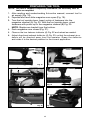
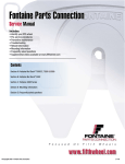
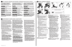
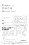
Staplers
Owners Manual
for models ENS100, ENS150
Record All Information and attach sales
receipt here for future reference:
Purchase Date:__________________________
Serial #: ________________________________
Do Not return this product to the retailer!
Questions? 1-800-888-2468
Learn more about your tool, get answers
to frequently asked questions, and
register on line at
www.devap.com
Copyright © 2004 DeVilbiss Air Power Company
IMPORTANT
Please make certain that the
person who is to use this
equipment carefully reads and
understands these instructions
before starting operations.
ESPAÑOL: PÁGINA 13
FRANÇAISE : PAGE 25
Part No. A05983 - 07-22-04
TABLE OF CONTENTS
SAFETY GUIDELINES AND INSTRUCTIONS . . . . . . . . . . . . . . . . . . . . . . .3
GENERAL SAFETY RULES . . . . . . . . . . . . . . . . . . . . . . . . . . . . . . . . . . . .4-6
FUNCTIONAL DESCRIPTION . . . . . . . . . . . . . . . . . . . . . . . . . . . . . . . . . . . .7
PREPARING THE TOOL . . . . . . . . . . . . . . . . . . . . . . . . . . . . . . . . . . . . . . . .8
OPERATING INSTRUCTIONS . . . . . . . . . . . . . . . . . . . . . . . . . . . . . . . .9-10
MAINTENANCE . . . . . . . . . . . . . . . . . . . . . . . . . . . . . . . . . . . . . . . . . . . . .10
SERVICE . . . . . . . . . . . . . . . . . . . . . . . . . . . . . . . . . . . . . . . . . . . . . . . . . . .11
TROUBLESHOOTING . . . . . . . . . . . . . . . . . . . . . . . . . . . . . . . . . . . . . . . .11
WARRANTY / SERVICE INFORMATION . . . . . . . . . . . . . . . . . . . . . . . . . .12
ESPAÑOL . . . . . . . . . . . . . . . . . . . . . . . . . . . . . . . . . . . . . . . . . . . . . . . .13-24
FRANÇAISE . . . . . . . . . . . . . . . . . . . . . . . . . . . . . . . . . . . . . . . . . . . . . .25-36
213 Industrial Drive • Jackson, TN 38301-9615
Telephone: 1-800-888-2468
FAX: 1-800-888-9036
Date of Manufacture:___________________________
Fecha de fabricación:, Date de fabrication:
Serial No:______________________________________
Número de serie:, Nombre d'ordre
2
SAFETY GUIDELINES / DEFINITIONS
It is important for you to read and understand this manual. The information it
contains relates to protecting YOUR SAFETY and PREVENTING PROBLEMS.
The symbols below are used to help you recognize this information.
indicates an imminently hazardous situation which, if not avoided,
will result in death or serious injury.
indicates a potentially hazardous situation which, if not avoided,
could result in death or serious injury.
indicates a potentially hazardous situation which, if not avoided,
may result in minor or moderate injury.
used without the safety alert symbol indicates potentially
hazardous situation which, if not avoided, may result in property
damage.
IMPORTANT SAFETY INSTRUCTIONS
SAVE THESE INSTRUCTIONS!
Read and understand all warnings and operating instructions
before using any tool or equipment. When using tools or equipment, basic
safety precautions should always be followed to reduce the risk of personal
injury. Improper operation, maintenance or modification of tools or equipment
could result in serious injury and property damage. There are certain
applications for which tools and equipment are designed. DeVilbiss Air Power
Company strongly recommends that this product NOT be modified and/or
used for any application other than for which it was designed.
If you have any questions relative to its application DO NOT use the product
until you have written DeVilbiss Air Power Company and we have advised you.
Online contact form at www.devap.com
Postal Mail:
Customer Care Department
213 Industrial Drive
Jackson, TN 38301-9615
Information regarding the safe and proper operation of this tool is available
from the following sources:
International Staple, Nail and Tool Association (ISANTA)
512 W. Burlington Ave., Suite 203, La Grange, IL 60525-2245
www.isanta.org
American National Standards Institute, 25 West 43rd Street, 4 floor, New York,
NY 10036 www.ansi.org
ANSI SNT-101-2002 Safety Requirements for Portable, Compressed-AirActuated Fastener Driving Power Tools
3
GENERAL SAFETY RULES
Read and understand tool labels and
manual. Failure to follow warnings could
result in DEATH or SERIOUS INJURY. Fig. 1.
Fig. 1
2. Operator and others in work area MUST
wear safety glasses with side shields.
These safety glasses must conform to ANSI
Z87.1 requirements (approved glasses have
“Z87” printed or stamped on them). Fig. 2.
3. Keep fingers AWAY from trigger when
not driving fasteners to avoid accidental
firing. Never carry tool with finger on
trigger. Contact actuation tools will fire a
fastener if the safety mechanism is bumped
while the trigger is depressed.
Fig. 2
Fig. 3
4. Choice of triggering method is
important. Check manual for triggering
options. See “Using the Tool“ section of
this manual.
5. Never point tool at yourself or others
in work area. Serious injury or death may
occur if the tool is activated. Fig. 3
6. Never use oxygen or other bottled
gases. Explosion will occur. Never use
combustible gases or any other reactive
gas as a power source for this tool:
explosion and serious personal injury will
result. Fig. 4.
Fig. 4
Fig. 5
7. Wear ear protection to safe-guard
against possible hearing loss. Ear
protection equipment must conform to ANSI
S3.19 requirements. Fig. 5.
8. Use clean, dry, regulated, compressed air at 70 to 110 PSI, (4.8 to 7.6
BAR). Fig
4
Fig. 6
9. Do not connect tool to pressure which
potentially exceeds 200 PSI (13.7 BAR).
10. All air line components (hoses,
connectors, filters, regulators, etc.) must
be rated for a maximum working pressure
of at least 150 PSI (10.3 BAR) or 150% of
the maximum system pressure, which ever
is greater.
Fig. 7
11. Connect tool to air supply hose with a
coupling that automatically removes all
pressure from the tool when the coupling is
disconnected. Fig. 7.
Fig. 8
12. Disconnect tool from air supply hose
before doing tool maintenance, clearing a
jammed fastener, leaving work area, moving
tool to another location, or handing the tool
to another person. Fig. 7.
Fig. 9
13. Never use a tool that is leaking air, has
missing or damaged parts, or requires
repair. Make sure all screws and caps are
securely tightened. Fig. 8.
14. Never use tool if safety, trigger or
springs are inoperable, missing or
damaged. Do not alter or remove safety,
trigger, or springs. Make daily inspections
for free movement of trigger and safety
mechanism. Fig. 8.
15. Do not use tool without safety
warning label. If label is missing, damaged
or unreadable, contact the Customer Care
Department at 1-800-888-2468 for a
replacement. Fig. 9.
16. Only use parts and accessories
approved by DeVilbiss Air Power Company.
Fig. 10
Fig. 11
17. Connect tool to air supply before
loading fasteners, to prevent a fastener
from being fired during connection. The tool
driving mechanism may cycle when tool is
connected to the air supply. Fig. 10.
18. Always assume the tool contains
fasteners. No horseplay. Respect the tool
as a working implement. Fig. 11.
19. Operator and bystanders should wear
hard hats to safeguard against possible
injuries. Fig. 12.
20. Keep bystanders and children away
from work area when operating this power
tool.
5
Fig. 12
21. Do not load fasteners with trigger or
safety depressed, to prevent unintentional
firing of a fastener. Fig. 13
22. Remove finger from trigger when not
driving fasteners. Never carry tool with finger
on trigger. Contact Actuation tools will fire a
fastener if the safety mechanism is bumped
while trigger is depressed. Fig. 14.
Fig. 13
Fig. 14
23. Do not overreach. Keep proper footing
and balance at all times when using or
handling the tool.
24. Fire fasteners into work surface only:
never into materials too hard to penetrate.
Fig. 15.
25. Grip tool firmly to maintain control
while allowing tool to recoil away from
work surface as fastener is driven. With
Contact Actuation tools an unwanted
fastener will be fired if the safety
mechanism is allowed to recontact work
surface before trigger is released.
26. Do not drive fasteners on top of other
fasteners, or with the tool at too steep an
angle: the fasteners can ricochet causing
personal injury. Fig. 15.
Fig. 15
Fig. 16
27. Do not drive fasteners close to the
edge of the workpiece. The workpiece is
likely to split allowing the fastener to fly free
or ricochet causing personal injury. Fig. 16.
28. FOR TOOLS USED IN CONTACT
ACTUATION MODE, Do not use on
scaffoldings or ladders or for tasks in
which changing location involves the use of
scaffoldings, stairs, ladders, and the like. Do
not use for specific tasks such as closing
boxes or crates or fitting transportation
safety systems on vehicles and wagons.
Fig. 17.
6
Fig. 17
EMPLOYER’S RESPONSIBILITIES
Employer must enforce compliance with the safety warnings and all other
instructions contained in this manual.
Keep this manual available for use by all people assigned to use this tool.
For personal safety and proper operation of this tool, read and understand
tool labels and manual. Failure to follow warnings could result in DEATH or
SERIOUS INJURY. Read and follow all of these instructions carefully.
FUNCTIONAL DESCRIPTION
Ex-Cell Model ENS100 is designed to install generic 18 ga. narrow (1/ 4")
crown staples of various lengths from 1/ 2" to 1" long. Narrow crown staples
are loaded into the magazine from the bottom.
Ex-Cell Model ENS150 is designed to install generic 18 ga. narrow (1/ 4")
crown staples of various lengths from 1/ 2" to 11/ 2" long. Narrow crown
staples are loaded into the magazine from the bottom.
Ex-Cell stapling tools are compact, lightweight, high performance tools
designed for molding, interior trim, paneling, cabinetry, picture/mirror frames
and crafts. Features include jam release mechanism, tool free adjustable
exhaust, fastener reload indicator, safety positioned on rear of nose and a
removable rubber nose cushion.
CARTON CONTENTS
1) Stapler
2) Staples
3) Air Tool Oil Bottle
4) Owner's Manual
POWER SOURCE
This tool is designed to operate on clean, dry, compressed air at regulated
pressures between 70 and 110 PSI (Pounds per Square Inch)(4.8 to 7.6 BAR).
The preferred system would include a filter, a pressure regulator, and an
automatic oiler located as close to the tool as possible, within 15 ft/4.6 m is
ideal. The tool is equipped with a 1/ 4" male “quick connector”.
All compressed air contains moisture and other contaminates that are
detrimental to internal components of the tool. An air line filter will remove
most of these contaminates and significantly prolong the life of the tool. If an
in-line oiler is not available: place five or six drops of Air Tool Oil into the tool’s
air inlet at the beginning of each workday.
7
PREPARING THE TOOL
NOTE: This tool is shipped completely assembled. No assembly time or
tools are required.
1. After reading and understanding this entire manual, connect tool to
air supply (Fig. 18).
2. Depress latch and slide magazine core open (Fig. 19).
3. Turn the tool upside down. Insert a strip of fasteners into the
magazine channel (A) Fig. 20. With the tool upside down, orient
fasteners with points up in the magazine channel (B) Fig. 20.
NOTE: Staples are loaded from the bottom.
4. Push magazine core closed (Fig. 21).
5. Observe the low fastener indicator (A) Fig. 22 and reload as needed.
6. Adjust directional exhaust deflector (A) Fig. 23, so that the exhaust air or
debris will be directed away from the operator. Grasp the deflector
and rotate it to the desired position for the current application.
Fig. 18
Fig. 20
Fig. 19
A
B
Fig. 21
A
A
Fig. 22
Fig. 23
8
OPERATING INSTRUCTIONS
USING THE TOOL
Complete all steps of PREPARING THE TOOL before using the tool.
This tool is shipped from the factory with a “single sequential actuation”
trigger. This actuation design requires the release of both the trigger and
safety mechanism after each fastener is driven. Sequential actuation is the
only triggering option available for this tool. To fire, grip the tool firmly to
maintain control, position nose of tool onto work surface, push the tool
firmly against work surface to depress safety (S) Fig. 24, and squeeze
trigger to fire a fastener. Allow tool to recoil away from work surface as
fastener is driven. This “single sequential actuation” method provides the
most accurate fastener placement.
Disconnect tool from
air supply before performing
maintenance, clearing a jammed
fastener, leaving work area, moving
tool to another location, or handing
the tool to another person.
Clean and inspect tool
daily. Carefully check for proper
operation of trigger and safety
mechanism. Do Not use the tool
unless both the trigger and the safety
mechanism are functional, or if the
tool is leaking air or needs any other
repair.
S
Fig. 24
RUBBER NOSE CUSHION
A rubber nose cushion (A) Fig. 25 is provided to reduce marring of the work
surface. The rubber cushion can be removed when it is not required.
Disconnect tool from
air supply before removing or
installing rubber cushion.
A
Fig. 25
9
CLEARING A JAMMED FASTENER
1.
2.
3.
4.
Disconnect tool from air supply.
Open magazine and remove remaining fasteners (Fig. 26 and Fig. 27).
NOTE: Remove fasteners from tool before opening the fastener
guide plate. Fasteners are under pressure and may shoot out of
magazine which could cause injury.
Depress the quick release latch and open the fastener guide plate
(Fig. 28).
Remove the jammed fastener (Fig. 29).
Depress the quick release latch and close the fastener guide plate.
Fig. 27
Fig. 26
Fig. 28
Fig. 29
MAINTENANCE
CLEAN AND INSPECT DAILY
Disconnect tool from air supply before cleaning and
inspection. Correct all problems before placing the tool back in use.
Wipe tool clean and inspect for wear or damage. Use non-flammable
cleaning solutions to wipe exterior of tool only if necessary. DO NOT SOAK
tool with cleaning solutions. Such solutions can damage internal parts.
Inspect trigger and safety mechanism to assure system is complete and
functional: no loose or missing parts, no binding or sticking parts.
Keep all screws tight. Loose screws can cause personal injury or damage
tool.
If tool is used without an in-line oiler: place 5 or 6 drops of Air Tool Oil into
the air inlet of the tool at the beginning of each workday.
10
SERVICE
SERVICE AND REPAIRS
All quality tools will eventually require servicing or replacement of parts due
to wear from normal use. For assistance with your tool, visit our website at
www.devap.com for a list of service centers or call the Customer Care
Department at 1-800-888-2468. All repairs made by our service centers are
fully guaranteed against defective material and workmanship. We cannot
guarantee repairs made or attempted by others.
Should you have any questions about your tool, feel free to write us at any
time. In any communications, please give all information shown on the
nameplate of your tool (model number, type, serial number, etc.).
TROUBLESHOOTING GUIDE
Disconnect tool from air supply before performing any Service
Procedure.
SYMPTOM
1. Air leak near top of
tool or in trigger area.
PROBLEMS
Loose screws.
Worn or damaged
o-rings or seals.
SOLUTIONS
Tighten screws.
Install Overhaul Kit.
2. Tool does nothing or
operates sluggishly.
Inadequate air supply.
Inadequate lubrication.
Worn or damaged
o-rings or seals.
Verify adequate air supply.
Put 5 or 6 drops of oil into air inlet.
Install Overhaul Kit.
3. Air leak near bottom
of tool.
Loose screws.
Worn or damaged
o-rings or bumper.
Tighten screws.
Install Overhaul Kit.
4. Tool jams frequently.
Incorrect fasteners.
Verify approved fasteners of
correct size.
Replace w/undamaged fasteners.
Tighten screws.
Damaged fasteners.
Magazine or nose
screws loose.
Magazine is dirty.
Driver is worn or damaged.
5. Other.
Clean magazine.
Install “DRIVER” Maintenance Kit.
Contact the Customer Care
Department at 1-800-888-2468.
11
WARRANTY
DeVilbiss Air Power Company warrants to the original purchaser who uses the product in a consumer
application (personal, residential or household usage) that all products covered under this warranty are
free from defects in material and workmanship for one year from the date of purchase. All products
covered by this limited warranty which are used in commercial applications (i.e., income producing)
are warranted to be free of defects in material and workmanship for 90 days from the date of original
purchase. Products covered under this warranty include air compressors, air tools, service parts,
pressure washers, nailers, staplers, and generators.
DeVilbiss Air Power Company will repair or replace, at DeVilbiss' option, products or components
which have failed within the warranty period. Service will be scheduled according to the normal work
flow and business hours at the service center location, and the availability of replacement parts. All
decisions of DeVilbiss Air Power Company with regard to this limited warranty shall be final.
This warranty gives you specific legal rights, and you may also have other rights which vary from state
to state.
RESPONSIBILITY OF ORIGINAL PURCHASER (initial User):
• To process a warranty claim on this product, DO NOT return it to the retailer. The product must be
evaluated by an Authorized Warranty Service Center. For the location of the nearest Authorized
Warranty Service Center call 1-800-888-2468, 24 hours a day, 7 days a week or visit our web site at
www.devap.com.
• Retain original cash register sales receipt as proof of purchase for warranty work.
• Use reasonable care in the operation and maintenance of the product as described in the Owners
Manual(s).
• Deliver or ship the product to the nearest Authorized Warranty Service Center. Freight costs, if any,
must be paid by the purchaser.
• Air compressors with 60 and 80 gallon tanks will be inspected at the site of installation. Contact the
nearest Authorized Warranty Service Center that provides on-site service calls for service call
arrangements.
• If the purchaser does not receive satisfactory results from the Authorized Warranty Service Center,
the purchaser should contact DeVilbiss Air Power Company.
THIS WARRANTY DOES NOT COVER:
• Merchandise sold as reconditioned, used as rental equipment, or floor or display models.
• Merchandise that has become damaged or inoperative because of ordinary wear, misuse*, cold,
heat, rain, excessive humidity, freeze damage, use of improper chemicals, negligence, accident,
failure to operate the product in accordance with the instructions provided in the Owners Manual(s)
supplied with the product, improper maintenance, the use of accessories or attachments not
recommended by DeVilbiss Air Power Company, or unauthorized repair or alterations.
* An air compressor that pumps air more than 50% during a one hour period is considered misuse
because the air compressor is undersized for the required air demand.
• Repair and transportation costs of merchandise determined not to be defective.
• Costs associated with assembly, required oil, adjustments or other installation and start-up costs.
• Expendable parts or accessories supplied with the product which are expected to become
inoperative or unusable after a reasonable period of use, including but not limited to sanding disks
or pads, saw and shear blades, grinding stones, springs, chisels, nozzles, o-rings, driver blades, air
jets, washers and similar accessories.
• Merchandise sold by DeVilbiss Air Power Company which has been manufactured by and identified
as the product of another company, such as gasoline engines. The product manufacturer's
warranty, if any, will apply.
• ANY INCIDENTAL, INDIRECT OR CONSEQUENTIAL LOSS, DAMAGE, OR EXPENSE THAT
MAY RESULT FROM ANY DEFECT, FAILURE OR MALFUNCTION OF THE PRODUCT IS NOT
COVERED BY THIS WARRANTY. Some states do not allow the exclusion or limitation of incidental
or consequential damages, so the above limitation or exclusion may not apply to you.
• IMPLIED WARRANTIES, INCLUDING THOSE OF MERCHANTABILITY OR FITNESS FOR A
PARTICULAR PURPOSE, ARE LIMITED TO ONE YEAR FROM THE DATE OF ORIGINAL
PURCHASE. Some states do not allow limitations on how long an implied warranty lasts, so the
above limitations may not apply to you.
213 Industrial Drive • Jackson, TN 38301-9615
Telephone: 1-800-888-2468
FAX: 1-800-888-9036
PC-0704-151