1
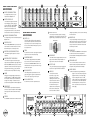
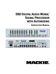
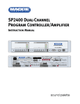
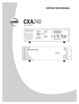
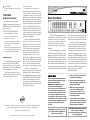
IEC AC SOCKET
Connect the supplied AC linecord to the IEC AC
Socket.
PC SOFTWARE
INSTALLING THE SOFTWARE
A PC-based Windows-style graphical
interface software application is provided on a
CD-ROM to control and configure the DX8 at the
point of installation.
TO INSTALL THE SOFTWARE ON A PC:
1.
Insert the DX8 CD-ROM into the CD drive.
2.
Make sure no other applications are open.
3.
Click Start, and then click Run.
4.
Type <drive>:\DX8-PC\Setup in the command line
(where <drive> is the letter assigned to the CD
drive, i.e., D drive)
5.
Setup will install the DX8-PC application onto your
PC. You can accept the default directory, or specify
a different location to install the application.
CONNECTING A PC
Use a standard DB9 (male/female) computer
cable to connect a PC to the DX8. COM 1 is
the default serial port selected in the software
application for the PC. Connect the COM port on
the PC to a COMM PORT on the DX8.
View the installed "Readme" file for more
information about running the PC application and
using a different serial port on the PC.
(continued from page 1)
Two independent RS232 connectors are
provided, one on the front panel and one on the
rear, for connection to a computer, control system,
or compatible PDA. A DB25 connector on the rear
panel allows interface between the 10 Logic Inputs
and 10 Logic Outputs to switches, LEDs and other
devices, enabling hardware control and indication
from custom control panels. All logic inputs and
outputs are fully programmable in software. A
proprietary remote control bus allows connection
of the optional DX8 wired remotes over a variety
of three-conductor cable. Remotes are available in
Volume Control and 4-switch versions and may be
combined in any configuration.
The DX8 is supplied with PC software that
allows access to all of the system’s settings and
configurations. The software offers Stereo and
Mono mixer views, as well as access to the two
1/3-octave equalizers, two 5-band parametric
equalizers and two compressors dedicated to
the two master outputs. In addition, it allows
configuration and recall of up to 16 Presets, 8
input Priority Levels, 8 Mute Groups and 8 Control
Groups. Force ON and OFF functions are provided,
with a selection of Relative or Absolute changes,
which can be used with the Priority settings to
create sophisticated audio management systems.
The DX8 is UL and CE approved and
designed for continuous use in professional fixed
installation systems. An internal auto-ranging
power supply allows connection to mains voltages
from 90-240V AC at 50/60 Hz without requiring
jumper or switch setting changes. A 24V DC
input is provided for applications where backup
battery power is required. Switchover to backup
power is automatic and silent.
EAW Commercial | Bldg 11 | One Main Street | Whitinsville, MA 01588 USA | www.eawcommercial.com
TEL: toll free in US & Canada 888.337.7404 | TEL outside US 425.892.6503 | FAX: 425.485.1152
UK 44.1268.570.808 | FAX 44.1268.570.809
Part No. SW0093 Rev. A 01/04 © 2004 LOUD Technologies Inc. All Rights Reserved.
DX8
8x2 Digital Mixer and Signal Processor
Quick-Start Guide
DX8 DIGITAL MIXER
POWER
The DX8 is a DSP-based digital audio mixer
and signal processor designed for use in a variety
of installations such as churches, courtrooms,
convention centers, and hotels. It provides eight
universal inputs and two balanced outputs
allowing true 8x2 mixing for stereo or dual zone
applications.
Each of the eight input channels is terminated
to two Phoenix-type detachable connectors, each
optimized to accept either mic or line-level signals.
Microphone preamplifiers use XDR™ technology
to offer studio-class audio performance. Phantom
power of 48V DC is switchable individually on each
input. Two auxiliary line-level inputs with trim are
provided, allowing analog signals to be mixed with
the A and B master mixes. Master outputs deliver
SAFETY FIRST!
Before connecting and using the equipment,
please read this Quick-Start Guide carefully
and keep it for future reference.
WARNING! This equipment has been
designed to be installed by qualified
professionals only! There are many factors to
be considered when installing professional
sound reinforcement systems. Some of these
factors include mechanical and electrical
considerations, as well as acoustic coverage
and performance. LOUD Technologies strongly
recommends that this equipment be installed
only by a professional sound installer or
contractor.
CAUTION: To avoid the risk of electric
shock, never allow this equipment to be
exposed to rain or dampness.
balanced line-level signals to detachable Phoenixtype connectors as well as buffered unbalanced
signals to RCA connectors intended for recording.
The DX8 offers an intuitive front panel user interface, consisting of dual-function LED bar graph
meters for each input and output. Input meters
indicate the presence of signal before signal processing (pre-fader), while output meters indicate
actual level at the output (post-fader). Levels are
set by means of UP/DOWN pushbuttons dedicated
to each input and output. A MODE button is used to
select between Mix A and B, allowing adjustment
of levels to both mix outputs from the same set of
input controls. A third function of the MODE button
allows the user to LOCK the front panel controls
until a security unlock code is entered.
(continued on last page)
1.
2.
3.
4.
5.
Never install, connect, or disconnect the
unit with the power supply on.
Before powering up the DX8, make sure
the AC voltage applied corresponds to the
markings on the rear panel.
Make sure the safety ground on the
power cord is properly grounded.
To prevent the risk of electric shock,
never open the unit. There are no userserviceable parts inside.
To ensure normal cooling of the DX810,
make sure the unit is well ventilated. Avoid
exposure to direct sunlight or proximity to
any heat source, dust, or dampness.
CAUTION: Internal lithium battery.
Danger of explosion if battery is
incorrectly replaced. Replace only with the
same or equivalent type.
FRONT PANEL FEATURES
AND CONTROLS
INPUT UP/DOWN BUTTONS
OL
OL
OL
OL
OL
OL
2
4
7
10
2
4
7
10
2
4
7
10
2
4
7
10
2
4
7
10
2
4
7
10
OL
15
12
9
6
3
2
4
7
10
Use to adjust the mix level for each
input channel to Output A or B.
DX8 DIGITAL MIXER
INPUT LED DISPLAY
This indicates the signal level after the
mic preamp stage, just after the A/D
converter. When any input UP/DOWN
button is pressed, the input meters
switch from level metering to level
setting indication. After five seconds, the meter
switches back to normal level (PPM) metering.
EQ LO/HI UP/DOWN BUTTONS
Use to adjust the gain of the 2-band shelving EQ on
Outputs A or B.
EQ LED DISPLAY
When an EQ UP/DOWN button is pressed, the EQ
meter indicates the amount of boost or cut of the
LO and HI frequencies in decibels (±15 dB).
MASTER A/B UP/DOWN BUTTONS
These buttons adjust the output level for each
output bus.
MASTER OUTPUT LED DISPLAY
This indicates the signal level after the digital
signal processing and MASTER gain stage. When a
MASTER UP/DOWN button is pressed, the master
output meter switches from level metering to level
setting indication. After five seconds, the meter
switches back to normal (PPM) level metering.
MODE
Changes the front panel buttons between Bus A
and Bus B operation. The LOCK position disables
the front panel controls to prevent unauthorized
changes to the settings. The default lock code
(1234) can be changed with the DX8-PC application.
A
1
2
3
4
5
6
7
8
LO
EQ
HI
A
MASTER
B
LOCK
MODE
B
POWER
COMM PORT
REAR PANEL FEATURES
AND CONTROLS
settings and conditions, as well as control switching
to external devices.
DIRECT OUTPUTS
This 15-pin D-Sub connector supplies an analog,
unbalanced line-level signal from each of the eight
program inputs, post-preamp and pre-processing.
INPUTS 1-8
Each of the eight analog inputs has separate balanced mic and line input connectors that use XDR
mic preamps. These are 3-pin Phoenix-type connectors. Use either the MIC or LINE input; only one can
be used per channel.
REMOTE BUS
This 3-pin Phoenix-type connector can be used to
attach optional remote controls to the DX8. Several
remote controls can be connected to each other in
a daisy-chain fashion to extend the remote control
functionality of the DX8.
DIRECT OUTPUTS
SIGNAL RETURN
SIGNAL RETURN
SIGNAL RETURN
SIGNAL RETURN
SIGNAL RETURN
SIGNAL RETURN
SIGNAL RETURN
TRIM
Use to trim the level of the input signal for optimum
signal-to-noise ratio in the preamp stage.
15
8
9
1
INPUT 1 HOT (+)
INPUT 2 HOT (+)
INPUT 3 HOT (+)
INPUT 4 HOT (+)
INPUT 5 HOT (+)
INPUT 6 HOT (+)
INPUT 7 HOT (+)
INPUT 8 HOT (+)
COMM PORT
This is identical to the COMM PORT on the front panel.
Use this to connect to an RS-232 serial port on a
personal computer or third-party controller for external
control of the DX8.
RECORD OUT
These RCA connectors supply unbalanced line-level
signals from the BUS A and BUS B outputs. The
signals are the same as the main outputs.
PHANTOM POWER
These switches apply phantom power (+48VDC)
to pins 2 and 3 of the selected mic input connectors. Switch the PHANTOM POWER switch for an
individual channel to the UP position when using a
condenser microphone.
EXPANSION SLOT
This is used for the DX810 to install the DX•10e
expansion board, which provides additional DSP
horsepower and eight more balanced outputs.
OUTPUTS A/B
These 3-pin Phoenix-type connectors supply a balanced line-level signal from BUS A and BUS B.
BUS A/B INPUTS
24VDC POWER
LOGIC I/O
These analog inputs accept balanced line-level
signals and route the signal to the internal buses.
There is no DSP processing on these inputs.
This 25-pin D-Sub connector provides 10 logic control
inputs and 10 logic control
outputs (open-collector). These
inputs can be used to control a
wide variety of DX8 functions
via external switching. The
outputs can be used to provide
status levels for external indicators for a number of internal
BUS A AND B TRIM
Use to trim the level of the inputs to the buses.
COMM PORT
An RS-232 port on a 9-pin D-Sub connector, which
connects to a personal computer or other compatible
control system for external control of the DX8 settings.
1 2 3 4 5 6 7 8
SERIAL NUMBER
POWER
LOGIC I/O
25
GROUND
N/C
LOGIC OUT 10
LOGIC OUT 9
LOGIC OUT 8
LOGIC OUT 7
LOGIC OUT 6
LOGIC OUT 5
LOGIC OUT 4
LOGIC OUT 3
LOGIC OUT 2
LOGIC OUT 1
14
13
1
The DX8 can be powered using a 24V DC power
supply. This can serve as the primary power
supply for the DX8, or as a backup supply
N/C
in case of an AC power failure. The DX8
N/C
LOGIC IN 10
seamlessly switches to the backup supply if
LOGIC IN 9
there’s a power loss. When both AC power
LOGIC IN 8
LOGIC IN 7
and 24V DC power are connected, the AC
LOGIC IN 6
LOGIC IN 5
power is used and no current is drawn from
LOGIC IN 4
LOGIC IN 3
the DC supply.
LOGIC IN 2
LOGIC IN 1
+5VDC
MANUFA
MANUFA
ACTURING
CTURING D
DAT
ATE
DX8 DIGITAL MIXER
Use the POWER switch to turn the DX8 on and off.
DIRECT OUTPUTS
U
U
U
U
U
U
U
U
U
U
C GAIN
MI
C GAIN
MI
C GAIN
MI
C GAIN
MI
C GAIN
MI
C GAIN
MI
C GAIN
MI
C GAIN
MI
60
0
-30dB +30dB
60
0
-30dB +30dB
60
0
-30dB +30dB
60
0
-30dB +30dB
60
0
-30dB +30dB
60
0
-30dB +30dB
60
0
-30dB +30dB
60
0
-30dB +30dB
12
-20
+20
TRIM
BUS A
POWER
INPUT
22-28V DC,
3A MAX
100 – 240V
0V
R
, 50/60Hz, 1A MAX
LIS
LISTED
COMMERCIAL
AUDIO EQUIPMENT
9Z39
–
MIC
+ G
G
LINE
+
-20
+20
TRIM
BUS B
TRIM
1
MIC
TRIM
2
MIC
TRIM
3
MIC
TRIM
4
MIC
TRIM
5
MIC
TRIM
6
MIC
TRIM
7
MIC
8
MIC
–
G 11
PHANTOM POWER
48V DC
–
+
LINE
LINE
LINE
LINE
LINE
LINE
LINE
LINE
LINE
INPUTS
1 +5V
TRIM
LINE
OUTPUTS
LOGIC I/O
1
REMOTE BUS
G
+
COMM PORT
–
OUTPUTS
A
B
RECORD
A
B
G
+
–
G
+
–