1
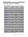
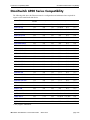
Part No. 060322-10 Rev. K March 2015 OmniSwitch AOS Release 7 Transceivers Guide www.alcatel-lucent.com This user guide contains transceiver specifications and compatibility information for the OmniSwitch AOS Release 7 and supported platforms. The information described in this guide is subject to change without notice. Attention: Use of any transceivers other than those part numbers listed in the Compatibility Matrices is prohibited. Failure to comply with these matrices is not guaranteed for proper performance and may result in voiding the warranty for the affected platforms. Alcatel, Lucent, Alcatel-Lucent and the Alcatel-Lucent logo are trademarks of Alcatel-Lucent. All other trademarks are the property of their respective owners. The information presented is subject to change without notice. Alcatel-Lucent assumes no responsibility for inaccuracies contained herein. Copyright © 2015 by Alcatel-Lucent. All rights reserved. This document may not be reproduced in whole or in part without the express written permission of Alcatel-Lucent. Service & Support Contact Information North America: 800-995-2696 Latin America: 877-919-9526 EMEA: +800 00200100 (Toll Free) or +1(650)385-2193 Asia Pacific: +65 6240 8484 Web: service.esd.alcatel-lucent.com Email: [email protected] Contents About This Guide ........................................................................................................... v Supported Platforms ........................................................................................................... v Who Should Read this Manual? ........................................................................................ vi When Should I Read this Manual? .................................................................................... vi What is Not in this Manual? .............................................................................................. vi How is the Information Organized? .................................................................................. vi Documentation Roadmap ................................................................................................. vii Related Documentation ..................................................................................................... ix Technical Support .............................................................................................................. x Chapter 1 Small Form-Factor Pluggables (SFP/SFP+/QSFP+) .......................................... 1-1 In This Chapter ................................................................................................................1-1 SFP MSA Specification ..................................................................................................1-2 Transceiver Installation and Removal .............................................................................1-3 Gigabit Ethernet Transceivers .........................................................................................1-6 Bi-directional Ethernet Transceivers ...............................................................................1-9 100 FX Ethernet Transceivers .......................................................................................1-12 CWDM Gigabit Ethernet Transceivers .........................................................................1-14 10-Gigabit SFP+ Transceivers ......................................................................................1-15 40-Gigabit QSFP+ Transceivers ...................................................................................1-19 Fibre Channel Transceivers ...........................................................................................1-21 Chapter 2 Transceiver Compatibility Matrix ......................................................................... 1-22 In This Chapter ..............................................................................................................1-22 OmniSwitch 10K Series Compatibility .........................................................................1-23 OmniSwitch 6900 Series Compatibility ........................................................................1-24 OmniSwitch AOS Release 7 Transceivers Guide March 2015 iii Contents iv OmniSwitch AOS Release 7 Transceivers Guide March 2015 About This Guide This OmniSwitch AOS Release 7 Transceivers Guide provides specifications and compatibility information for the supported OmniSwitch transceivers for all OmniSwitch AOS Release 7 Products. Supported Platforms This information in this guide applies to the following products: • OmniSwitch 10K • OmniSwitch 6900 Unsupported Platforms The information in this guide does not apply to the following products: • All other platforms OmniSwitch AOS Release 7 Tranceivers Guide March 2015 page v Who Should Read this Manual? About This Guide Who Should Read this Manual? The audience for this user guide is network administrators and IT support personnel who need to provide network connectivity using SFP, SFP+, and QSFP+ transceivers. When Should I Read this Manual? Read this guide as soon as you are ready to integrate your OmniSwitch into your network and you are ready to provide connectivity using the supported transceivers. You should have already stepped through the first login procedures and read the brief software overviews in the appropriate OmniSwitch Getting Started Guide and OmniSwitch Hardware Guide. This guide includes information about the supported OmniSwitch transceivers. • SFP/SFP+/QSFP+ specifications • SFP/SFP+/QSFP+ compatibility information What is Not in this Manual? Procedures for switch management methods, such as CLI, web-based (WebView or OmniVista) or SNMP, are outside the scope of this guide. For information on WebView and SNMP switch management methods consult the OmniSwitch Switch Management Guide. Information on using WebView and OmniVista can be found in the context-sensitive on-line help available with those network management applications. This guide is designed to provide transceiver specification and compatibility information only and is not intended as a reference for any CLI commands or configuration information. Refer to the Documentation Roadmap for a list of available user guides. How is the Information Organized? Chapters in this guide are broken down by transceiver type. Specification Information. Each transceiver has an associated table providing individual specifications for all supported transceivers. Compatibility Information. A compatibility chart is provided for each transceiver specifying which modules or switch the transceiver is supported on. page vi OmniSwitch AOS Release 7 Tranceivers Guide March 2015 About This Guide Documentation Roadmap Documentation Roadmap The OmniSwitch user documentation suite was designed to supply you with information at several critical junctures of the configuration process.The following section outlines a roadmap of the manuals that will help you at each stage of the configuration process. Under each stage, we point you to the manual or manuals that will be most helpful to you. Stage 1: Using the Switch for the First Time Pertinent Documentation: OmniSwitch Getting Started Guide Release Notes This guide provides all the information you need to get your switch up and running the first time. It provides information on unpacking the switch, rack mounting the switch, installing NI modules, unlocking access control, setting the switch’s IP address, and setting up a password. It also includes succinct overview information on fundamental aspects of the switch, such as hardware LEDs, the software directory structure, CLI conventions, and web-based management. At this time you should also familiarize yourself with the Release Notes that accompanied your switch. This document includes important information on feature limitations that are not included in other user guides. Stage 2: Gaining Familiarity with Basic Switch Functions Pertinent Documentation: OmniSwitch Hardware Users Guide OmniSwitch AOS Release 7 Switch Management Guide Once you have your switch up and running, you will want to begin investigating basic aspects of its hardware and software. Information about switch hardware is provided in the OmniSwitch 10K Hardware Guide. This guide provide specifications, illustrations, and descriptions of all hardware components, such as chassis, power supplies, Chassis Management Modules (CMMs), Network Interface (NI) modules, and cooling fans. It also includes steps for common procedures, such as removing and installing switch components. This guide is the primary users guide for the basic software features on a single switch. This guide contains information on the switch directory structure, basic file and directory utilities, switch access security, SNMP, and web-based management. It is recommended that you read this guide before connecting your switch to the network. Stage 3: Integrating the Switch Into a Network Pertinent Documentation: OmniSwitch AOS Release 7 Network Configuration Guide OmniSwitch AOS Release 7 Advanced Routing Configuration Guide OmniSwitch AOS Release 7 Data Center Switching Guide When you are ready to connect your switch to the network, you will need to learn how the OmniSwitch implements fundamental software features, such as 802.1Q, VLANs, Spanning Tree, and network routing protocols. The Network Configuration Guide contains overview information, procedures, and examples on how standard networking technologies are configured on the OmniSwitch. The Advanced Routing Guide includes configuration information for networks using advanced routing technologies (OSPF and BGP) and multicast routing protocols (DVMRP and PIM-SM). The Data Center Switching Guide includes configuration information for data center networks using virtualization technologies (SPBM and UNP) and Data Center Bridging protocols (PFC, ETC, and DCBX). OmniSwitch AOS Release 7 Tranceivers Guide March 2015 page vii Documentation Roadmap About This Guide Anytime The OmniSwitch AOS Release 7 CLI Reference Guide contains comprehensive information on all CLI commands supported by the switch. This guide includes syntax, default, usage, example, related CLI command, and CLI-to-MIB variable mapping information for all CLI commands supported by the switch. This guide can be consulted anytime during the configuration process to find detailed and specific information on each CLI command. page viii OmniSwitch AOS Release 7 Tranceivers Guide March 2015 About This Guide Related Documentation Related Documentation The following are the titles and descriptions of all the OmniSwitch user manuals: • OmniSwitch 10K Getting Started Guide Describes the hardware and software procedures for getting an OmniSwitch up and running. Also provides information on fundamental aspects of OmniSwitch software architecture. • OmniSwitch 10K and OmniSwitch 6900 Hardware Users Guides Complete technical specifications and procedures for all OmniSwitch chassis, power supplies, fans, and Network Interface (NI) modules. • OmniSwitch AOS Release 7 CLI Reference Guide Complete reference to all CLI commands supported on the OmniSwitch. Includes syntax definitions, default values, examples, usage guidelines and CLI-to-MIB variable mappings. • OmniSwitch AOS Release 7 Switch Management Guide Includes procedures for readying an individual switch for integration into a network. Topics include the software directory architecture, image rollback protections, authenticated switch access, managing switch files, system configuration, using SNMP, and using web management software (WebView). • OmniSwitch AOS Release 7 Network Configuration Guide Includes network configuration procedures and descriptive information on all the major software features and protocols included in the base software package. Chapters cover Layer 2 information (Ethernet and VLAN configuration), Layer 3 information (routing protocols, such as RIP and IPX), security options (authenticated VLANs), Quality of Service (QoS), link aggregation, and server load balancing. • OmniSwitch AOS Release 7 Advanced Routing Configuration Guide Includes network configuration procedures and descriptive information on all the software features and protocols included in the advanced routing software package. Chapters cover multicast routing (DVMRP and PIM-SM), Open Shortest Path First (OSPF), and Border Gateway Protocol (BGP). • OmniSwitch AOS Release 7 Data Center Switching Guide Includes and introduction to the OmniSwitch data center switching architecture as well as network configuration procedures and descriptive information on all the software features and protocols that support this architecture. Chapters cover Shortest Path Bridging MAC (SPBM), Data Center Bridging (DCB) protocols, Virtual Network Profile (vNP), and the Edge Virtual Bridging (EVB) protocol. • OmniSwitch AOS Release 7 Transceivers Guide Includes transceiver specifications and product compatibility information. • Technical Tips, Field Notices Includes information published by Alcatel’s Customer Support group. • Release Notes Includes critical Open Problem Reports, feature exceptions, and other important information on the features supported in the current release and any limitations to their support. OmniSwitch AOS Release 7 Tranceivers Guide March 2015 page ix Technical Support About This Guide Technical Support An Alcatel-Lucent service agreement brings your company the assurance of 7x24 no-excuses technical support. You’ll also receive regular software updates to maintain and maximize your Alcatel-Lucent product’s features and functionality and on-site hardware replacement through our global network of highly qualified service delivery partners. With 24-hour access to Alcatel-Lucent’s Service and Support web page, you’ll be able to view and update any case (open or closed) that you have reported to Alcatel-Lucent’s technical support, open a new case or access helpful release notes, technical bulletins, and manuals. Access additional information on Alcatel-Lucent’s Service Programs: Web: service.esd.alcatel-lucent.com Phone: 1-800-995-2696 Email: [email protected] page x OmniSwitch AOS Release 7 Tranceivers Guide March 2015 1 Small Form-Factor Pluggables (SFP/SFP+/QSFP+) OmniSwitch Series switches use both copper-based and fiber-based optical Small Form Factor Pluggable transceivers. These transceivers are fully hot-swappable and are available for both short-reach and longreach applications. Copper-based and fiber-based optical transceivers can be mixed on the same module. In This Chapter This chapter describes the technical specifications for all the OmniSwitch supported transceivers. For additional details about OmniSwitch modules, see the appropriate OmniSwitch Hardware Guide. Transceiver specifications in this chapter include: • SFP MSA Specifications. See “SFP MSA Specification” on page 1-1 • Transceiver Installation. See “Transceiver Installation and Removal” on page 1-3 • Gigabit Ethernet Transceivers. See “Gigabit Ethernet Transceivers” on page 1-6. • Bi-directional Ethernet Transceivers. See “Bi-directional Ethernet Transceivers” on page 1-9. • 100-FX Ethernet Transceivers. See “100 FX Ethernet Transceivers (cont.)” on page 1-13. • CWDM Gigabit Ethernet Transceivers. See “CWDM Gigabit Ethernet Transceivers” on page 1-14. • 10-Gigabit SFP+ Transceivers. See “10-Gigabit SFP+ Transceivers” on page 1-15 • 40-Gigabit QSFP+ Transceivers. See “40-Gigabit QSFP+ Transceivers” on page 1-19 • Fibre Channel Transceivers. See “Fibre Channel Transceivers” on page 1-22 • For a transceiver compatibility matrix, see “Transceiver Compatibility Matrix” on page 2-23. SFP MSA Specification OmniSwitch AOS Release 7 Transceivers Guide March 2015 page 1-1 SFP MSA Specification Small Form-Factor Pluggables (SFP/SFP+/QSFP+) The Small Form-Factor Pluggable (SFP) MSA (Multi Source Agreement) is a specification for a common interface for optical modular transceivers. The SFP connector consists of a 20-pin receptacle and an SFP housing cage. The connector provides the interface for the hot pluggable SFP module. Each SFP module contains a serial interface to provide identification information that describes the SFP capabilities, stand interfaces, manufacturer and other information. For information on installing SFPs, refer to the documentation included with the transceiver. This diagram is a representation only; the physical appearance of the actual module may vary slightly. Small Form Factor Pluggable (SFP) page 1-2 OmniSwitch AOS Release 7 Transceivers Guide March 2015 Small Form-Factor Pluggables (SFP/SFP+/QSFP+) Transceiver Installation and Removal Transceiver Installation and Removal Follow the instructions below for the appropriate transceiver type. ESD Caution: Before handling the module, you must discharge all static electricity on your person to avoid Electrostatic Discharge (ESD) damage. If using a wrist strap, ensure that the wrist strap touches your skin. Attach the other end of the strap to the chassis. If your chassis provides a grounding lug, this can be used. Refer to your hardware user guide for details. If using a wrist strap, ensure that the wrist strap touches your skin. Attach the other end of the strap to the chassis. If your chassis provides a grounding lug, this can be used. Refer to your hardware user guide for details. Dust Exposure: To reduce the risk of dust exposure and physical damage, be sure to replace the protective rubber cover (provided) when the SFP is not in use. Eye Safety: SFP transceivers are international Class 1 laser products and are eye-safe devices when operated within the limits of manufacturers’ specifications. Operating SFP transceivers in a manner inconsistent with intended usage and specification may result in hazardous radiation exposure. Note: After removing a transceiver, wait for a minimum of 5 seconds before re-inserting any transceiver into the same port. This allows sufficient time for software to detect the removal of the transceiver. Note: Never force the transceiver in or out of the transceiver slot. Interface Slot To remove, you must first open the SFP’s hinged face to approximately ninety degrees. Then, grasp the hinged face and carefully pull the SFP straight out of the slot. When inserting a SFP, be sure that the hinged face is closed. Slide the SFP straight into the slot until the module clicks firmly into place. SFP Module SFP - Hinged OmniSwitch AOS Release 7 Transceivers Guide March 2015 page 1-3 Transceiver Installation and Removal Small Form-Factor Pluggables (SFP/SFP+/QSFP+) To install, align the transceiver with the transceiver slot on the NI module, as shown. Be sure that the bail wire delatch is in the up, or closed position. Slide the transceiver straight into the slot until the module clicks firmly into place. To remove, you must first pull down on the bail wire delatch. Grip the wire delatch while it is in this open position and carefully pull the transceiver straight out of the slot. SFP Transceiver Transceiver Slot Bail Wire Delatch (Shown in open “removal” position; when inserting, bail delatch must be closed.) Network Interface (NI) Module SFP - Bail Wire To install, align the transceiver with the transceiver slot on the NI module, as shown. Carefully slide the transceiver back until it clicks into place; this is an indication that the connectors are firmly seated. Network Interface (NI) Module SFP Transceiver To remove, use the ejector tool (provided with each switch chassis) to push the transceiver’s ejector button. The ejector button is located just below the transceiver port; refer to the diagram for more information. The transceiver will disengage from the connectors and eject slightly. Once disengaged, use the clip end of the ejector tool to carefully pull the transceiver straight out and away from the NI module. Transceiver Slot Ejector Dust Cover SFP - Ejector Button page 1-4 OmniSwitch AOS Release 7 Transceivers Guide March 2015 Small Form-Factor Pluggables (SFP/SFP+/QSFP+) To install, align the transceiver with the transceiver slot on the NI module, as shown. Carefully slide the transceiver back until it clicks into place; this is an indication that the connectors are firmly seated. Transceiver Installation and Removal Network Interface (NI) Module QSFP+ Transceiver To remove, use the rubber or metal ejector handle and pull transceiver straight out and away from the NI module. Note: Never force the transceiver in or out of the transceiver slot. Transceiver Slot Handle QSFP+ - Removal OmniSwitch AOS Release 7 Transceivers Guide March 2015 page 1-5 Gigabit Ethernet Transceivers Small Form-Factor Pluggables (SFP/SFP+/QSFP+) Gigabit Ethernet Transceivers SFP-GIG-SX Gigabit SFP Optical Transceiver. Connector Type LC Standards Supported 802.3z, SFP MSA Connections Supported 1000Base-SX Fiber Type MMF Wavelength 850 nm Optical Power Output -9.0 to -3 dBm Receiver Sensitivity -20 dBm Transmission Distance ~300 m on 62.5/125µm ~550 m on 50/125µm Operating Temperature 0 ºC to 70 ºC Digital Diagnostic Monitoring Not Supported SFP-GIG-LX Gigabit SFP Optical Transceiver. Connector types LC Standards supported 802.3z, SFP MSA Connections supported 1000Base-LX Fiber Type SMF Wavelength 1310 nm Optical Power Output -9.5 to -3 dBm Receiver Sensitivity -14.5 dBm Transmission Distance 10 km Operating Temperature -40 ºC to 85 ºC / 0 ºC to 70 ºC Digital Diagnostic Monitoring Not Supported page 1-6 OmniSwitch AOS Release 7 Transceivers Guide March 2015 Small Form-Factor Pluggables (SFP/SFP+/QSFP+) Gigabit Ethernet Transceivers Gigabit Ethernet Transceivers (cont.) SFP-GIG-LH70 Gigabit SFP Optical Transceiver. Connector Type LC Standards Supported 802.3z, SFP MSA Connections Supported 1000Base-LH70 Fiber Type SMF Wavelength 1550 nm Optical Power Output 0 to +5 dBm Receiver Sensitivity -22 dBm Transmission Distance ~70 km Operating Temperature -10 ºC to 70 ºC Digital Diagnostic Monitoring Supported SFP-GIG-LH40 Gigabit SFP Optical Transceiver. Connector Type LC Standards Supported 802.3z, SFP MSA Connections Supported 1000Base-LH40r Fiber Type SMF Wavelength 1310 nm Optical Power Output 0 to +5 dBm Receiver Sensitivity -22 dBm Transmission Distance ~40 km Operating Temperature -10 ºC to 70 ºC Digital Diagnostic Monitoring Supported OmniSwitch AOS Release 7 Transceivers Guide March 2015 page 1-7 Gigabit Ethernet Transceivers Small Form-Factor Pluggables (SFP/SFP+/QSFP+) Gigabit Ethernet Transceivers (cont.) SFP-GIG-T Gigabit SFP Copper Transceiver. Connector Type RJ-45 Standards Supported 802.3z, SFP MSA Connections supported 10/100/1000Base-T Cable Type CAT5, CAT5e, CAT6 Transmission Distance 100 m Digital Diagnostic Monitoring Not Supported SFP-GIG-EXTND Gigabit SFP Optical Transceiver. Connector Type LC Standards Supported 802.3, SFP MSA Connections Supported - Fiber Type MMF Wavelength 1310 nm Saturation Power 0 dBm Transmission Distance ~2 km Operating Temperature 0 ºC to 70 ºC Digital Diagnostic Monitoring Supported page 1-8 OmniSwitch AOS Release 7 Transceivers Guide March 2015 Small Form-Factor Pluggables (SFP/SFP+/QSFP+) Bi-directional Ethernet Transceivers Bi-directional Ethernet Transceivers SFP-100-BX20LT Bi-Directional SFP Optical Transceiver. Connector Type SC Standards Supported 802.3ah, SFP MSA, ITU-T G.983 Connections Supported 100Base-BX Fiber Type SMF Wavelength Transmit: 1550 mm Receive: 1310 nm Average Power Output -14 to -8 dBm Receiver Sensitivity -32 dBm Transmission Distance ~20 km Operating Temperature 0 ºC to 70 ºC Digital Diagnostic Monitoring Supported Notes Designed for use with SFP-100-BX20NU SFP-100-BX20NU Bi-Directional SFP Optical Transceiver. Connector Type SC Standards Supported 802.3ah, SFP MSA, ITU-T G.983 Connections Supported 100Base-BX Fiber Type SMF Wavelength Transmit: 1310 nm Receive: 1550 nm Average Power Output -14 to -8 dBm Receiver Sensitivity -32 dBm Transmission Distance ~20 km Operating Temperature 0 ºC to 70 ºC Digital Diagnostic Monitoring Supported Notes Designed for use with SFP-100-BX20LT OmniSwitch AOS Release 7 Transceivers Guide March 2015 page 1-9 Bi-directional Ethernet Transceivers Small Form-Factor Pluggables (SFP/SFP+/QSFP+) Bi-directional Ethernet Transceivers (cont.) SFP-100-BXLC-D Bi-Directional SFP Optical Transceiver. Connector Type LC Standards Supported 802.3ah, SFP MSA, ITU-T G.983 Connections Supported 100Base-BX Fiber Type SMF Wavelength Transmit: 1550 mm Receive: 1310 nm Average Power Output -14 to -8 dBm Receiver Sensitivity -32 dBm Transmission Distance ~20 km Operating Temperature 0 ºC to 70 ºC Digital Diagnostic Monitoring Supported Notes Designed for use with SFP-100-BXLC-U SFP-100-BXLC-U Bi-Directional SFP Optical Transceiver. Connector Type LC Standards Supported 802.3ah, SFP MSA, ITU-T G.983 Connections Supported 100Base-BX Fiber Type SMF Wavelength Transmit: 1310 nm Receive: 1550 nm Average Power Output -14 to -8 dBm Receiver Sensitivity -32 dBm Transmission Distance ~20 km Operating Temperature 0 ºC to 70 ºC Digital Diagnostic Monitoring Supported Notes Designed for use with SFP-100-BXLC-D page 1-10 OmniSwitch AOS Release 7 Transceivers Guide March 2015 Small Form-Factor Pluggables (SFP/SFP+/QSFP+) Bi-directional Ethernet Transceivers Bi-directional Ethernet Transceivers (cont.) SFP-GIG-BX-D Bi-Directional SFP Optical Transceiver. Connector Type LC Standards Supported 802.3ah, SFP MSA Connections Supported 1000Base-BX10 Fiber Type SMF Wavelength Transmit: 1490 mm Receive: 1310 nm Average Power Output -9 to -3 dBm Receiver Sensitivity -19.5 dBm Transmission Distance ~10 km Operating Temperature 0 ºC to 70 ºC Digital Diagnostic Monitoring Supported Notes Designed for use with SFP-GIG-BX-U SFP-GIG-BX-U Bi-Directional SFP Optical Transceiver. Connector Type LC Standards Supported 802.3ah, SFP MSA Connections Supported 1000Base-BX10 Fiber Type SMF Wavelength Transmit: 1310 nm Receive: 1490 nm Average Power Output -9 to -3 dBm Receiver Sensitivity -19.5 dBm Transmission Distance ~10 km Operating Temperature 0 ºC to 70 ºC Digital Diagnostic Monitoring Supported Notes Designed for use with SFP-GIG-BX-D OmniSwitch AOS Release 7 Transceivers Guide March 2015 page 1-11 100 FX Ethernet Transceivers Small Form-Factor Pluggables (SFP/SFP+/QSFP+) 100 FX Ethernet Transceivers SFP-100-LC-MM SFP Optical Transceiver. Connector Type LC Standards Supported 802.3u, SFP MSA Connections supported 100Base-FX Fiber Type MMF Wavelength 1310 nm Optical Power Output -19 to -14 dBm on 62.5/125µm -22 to 14 dBm on 50/125µm Transmission Distance ~2 km on 62.5/125µm ~2 km on 50/125µm Operating Temperature 0 ºC to 70 ºC Digital Diagnostic Monitoring Not Supported SFP-100-LC-SM15 SFP Optical Transceiver. Connector Type LC Standards Supported 802.3u, SFP MSA Connections Supported 100Base-FX Fiber Type SMF Wavelength (nm) 1310 nm Optical Power Output -15 to -8 dBm Receiver Sensitivity -34 dBm Transmission Distance ~15 km Operating Temperature 0 ºC to 70 ºC Digital Diagnostic Monitoring Not Supported page 1-12 OmniSwitch AOS Release 7 Transceivers Guide March 2015 Small Form-Factor Pluggables (SFP/SFP+/QSFP+) 100 FX Ethernet Transceivers 100 FX Ethernet Transceivers (cont.) SFP-100-LC-SM40 SFP Optical Transceiver. Connector Type LC Standards Supported 802.3u, SFP MSA Connections Supported 100Base-FX Fiber Type SMF Wavelength 1310 nm Optical Power Output -15 to -8 dBm Receiver Sensitivity -34 dBm Transmission Distances ~40 km Operating Temperature 0 ºC to 70 ºC Digital Diagnostic Monitoring Not Supported OmniSwitch AOS Release 7 Transceivers Guide March 2015 page 1-13 CWDM Gigabit Ethernet Transceivers Small Form-Factor Pluggables (SFP/SFP+/QSFP+) CWDM Gigabit Ethernet Transceivers . SFP-GIG-CWD Coarse Wavelength Division Multiplexing (CWDM) is an optical transceiver supporting single-mode fiber over various wavelengths. CWDMs are hot-pluggable and are available for long-reach applications. Connector Type LC Standards Supported 802.3z, SFP MSA Connections Supported 1000Base-LX Fiber Type SMF Wavelength 1470, 1490, 1510, 1530, 1550, 1570, 1590, 1610 Optical Power Output -2 to +3 dBm Receiver Sensitivity -24 dBm Transmission Distances ~62 km Operating Temperature -5 ºC to 70 ºC Digital Diagnostic Monitoring Not Supported page 1-14 OmniSwitch AOS Release 7 Transceivers Guide March 2015 Small Form-Factor Pluggables (SFP/SFP+/QSFP+) 10-Gigabit SFP+ Transceivers 10-Gigabit SFP+ Transceivers SFP-10G-SR 10-Gigabit SFP+ Optical Transceiver. Connector Type LC Standards Supported 802.3 Clause 52 Connections supported 10GBase-SR Fiber Type MMF Wavelength 850 nm Optical Power Output -7.3 to -3.0 dBm Receiver Sensitivity -11.1 dBm Transmission Distance ~ 300 m Operating Temperature -5 ºC to 70ºC Maximum Power Consumption 1W Digital Diagnostic Monitoring Supported SFP-10G-LR 10-Gigabit SFP+ Optical Transceiver. Connector Type LC Standards Supported 802.3 Clause 52 Connections supported 10GBase-LR Fiber Type SMF Wavelength 1310 nm Optical Power Output -8.2 to 0.5 dBm Receiver Sensitivity -10.3 dBm Transmission Distance ~ 10 km Operating Temperature -5 ºC to 70ºC Maximum Power Consumption 1W Digital Diagnostic Monitoring Supported OmniSwitch AOS Release 7 Transceivers Guide March 2015 page 1-15 10-Gigabit SFP+ Transceivers Small Form-Factor Pluggables (SFP/SFP+/QSFP+) SFP-10G-ER 10-Gigabit SFP+ Optical Transceiver. Connector Type LC Standards Supported 802.3ae Connections supported 10GBase-E Fiber Type SMF Wavelength 1550 nm Optical Power Output -4.7 to 4.0 dBm Receiver Sensitivity -14.1 dBm Transmission Distance ~ 40 km Operating Temperature -5 ºC to 70 ºC Maximum Power Consumption 1.5 W Digital Diagnostic Monitoring Supported SFP-10G-ZR 10-Gigabit SFP+ Optical Transceiver. Connector Type LC Standards Supported 802.3ae Connections supported 10GBase-ZR Fiber Type SMF Wavelength 1550 nm Optical Power Output 0 to +5 dBm Receiver Sensitivity -20 dBm Transmission Distance ~ 80 km Operating Temperature -5 ºC to 70 ºC Maximum Power Consumption 1.2 W Digital Diagnostic Monitoring Supported page 1-16 OmniSwitch AOS Release 7 Transceivers Guide March 2015 Small Form-Factor Pluggables (SFP/SFP+/QSFP+) 10-Gigabit SFP+ Transceivers SFP-10G-LRM 10-Gigabit SFP+ Optical Transceiver. Connector Type LC Standards Supported 802.3aq Connections supported 10GBase-LRM Fiber Type MMF Wavelength 1310 nm Optical Power Output -4.5 to 1.5dBm Receiver Sensitivity -6.5 dBm Transmission Distance ~ 220 m Operating Temperature -5 ºC to 70ºC Maximum Power Consumption 1 Watt Digital Diagnostic Monitoring Supported SFP-10G-24DWD80 10-Gigabit SFP+ Optical Transceiver. Connector Type LC Standards Supported 802.3ae Connections supported 10GBase-ZR Fiber Type SMF Wavelength 1558.17 nm Optical Power Output 0 to 5dBm Receiver Sensitivity -23 dBm Transmission Distance ~ 80 km Operating Temperature -5ºC to 70ºC Maximum Power Consumption 1.2 Watt Digital Diagnostic Monitoring Supported OmniSwitch AOS Release 7 Transceivers Guide March 2015 page 1-17 10-Gigabit SFP+ Transceivers Small Form-Factor Pluggables (SFP/SFP+/QSFP+) SFP-10G-GIG-SR 10-Gigabit SFP+ Optical Transceiver. Connector Type LC Standards Supported 802.3-2005 Connections supported 10GBase-SR/SW, 1000Base-SX Fiber Type MMF Wavelength 850 nm Optical Power Output -5 to -1 @ 10G -9.5 to -1dBm @ 1G Receiver Sensitivity -11.1 dBm @ 10G -17 dBm @ 1G Transmission Distance OM1: ~33m @ 10G, ~275m @ 1G OM2: ~82m @ 10G, ~550m @ 1G OM3: ~300m @ 10G, ~550m @ 1G Operating Temperature 0ºC to 70ºC Maximum Power Consumption <1.0 Watt Digital Diagnostic Monitoring Supported SFP-10G-C 10-Gigabit SFP+ Direct Attach Copper Cable. Connector Type Direct Attached Copper Standards Supported 802.3ae, SFF-8431 Cable Length 1m, 3m, 7m1 Wire Gauge 24AWG Bend Radius 1.25 in. Digital Diagnostic Monitoring Not Supported 1. Check for availability of additional supported lengths. page 1-18 OmniSwitch AOS Release 7 Transceivers Guide March 2015 Small Form-Factor Pluggables (SFP/SFP+/QSFP+) 40-Gigabit QSFP+ Transceivers 40-Gigabit QSFP+ Transceivers CAUTION - CLASS 1M LASER RADIATION WHEN OPEN. DO NOT VIEW DIRECTLY WITH OPTICAL INSTRUMENTS. QSFP-40G-SR Four channel 40-Gigabit QSFP+ Optical Transceiver. Connector Type MPO Standards Supported 802.3ba, QSFP+ MSA Connections supported 40GBase-SR4 Fiber Type MMF Wavelength 850 nm Optical Power Output -7.6 to +2.4 dBm Receiver Sensitivity -5.4 dBm Transmission Distance OM3 - ~ 100 m OM4 - ~150 m Operating Temperature 0 ºC to 70ºC Maximum Power Consumption 1.5 W Digital Diagnostic Monitoring Supported1 QSFP-40G-LR Four channel 40-Gigabit QSFP+ Optical Transceiver. Connector Type LC Standards Supported 802.3ba, QSFP+ MSA Connections supported 40GBase-LR4 Fiber Type SMF Wavelength 1310 nm Optical Power Output -7.0 to +2.3 dBm Receiver Sensitivity -11.5 dBm Transmission Distance 10 km Operating Temperature 0 ºC to 70ºC Maximum Power Consumption < 3.5 W Digital Diagnostic Monitoring Supported1 1. Supports the DDM parameters of Voltage (V), Temperature (T), Current (mA) and Input (dBm). If the threshold values of the transceiver are ‘0’ then NS will be displayed in the DDM output display. OmniSwitch AOS Release 7 Transceivers Guide March 2015 page 1-19 40-Gigabit QSFP+ Transceivers Small Form-Factor Pluggables (SFP/SFP+/QSFP+) QSFP-40G-C Four channel 40-Gigabit QSFP+ Direct Attach Copper Cable Connector Type Direct Attached Copper Standards Supported 802.3ba, QSFP+ MSA Cable Length 1m, 3m, 7m1,2 Wire Gauge 26AWG Bend Radius 1.69 in. Digital Diagnostic Monitoring Not Supported 1. Check for availability of lengths. 2. The QSFP-40G-C7 (7m) cable has been verified for proper operation when connected between OmniSwitch products. When connecting this cable between an OmniSwitch and other vendors’ equipment, it’s recommended to verify proper operation prior to network deployment. QSFP-4X10G-SR Four channel 40-Gigabit QSFP+ Optical Transceiver. Connects a single 40G QSFP+ port to four 10G SFP+ ports Connector Type MPO Standards Supported 802.3ba, 802.3ae, QSFP+ MSA Connections supported 40GBase-SR4, 10GBase-SR Fiber Type MMF Wavelength 850 nm Optical Power Output -7.5 to +0.5 dBm Receiver Sensitivity -7.5 dBm (SRS) Transmission Distance OM3 - ~ 300 m OM4 - ~400 m Operating Temperature 0 ºC to 70ºC Maximum Power Consumption 1.5 W Digital Diagnostic Monitoring Supported Example MPO Splitter Cable page 1-20 OmniSwitch AOS Release 7 Transceivers Guide March 2015 Small Form-Factor Pluggables (SFP/SFP+/QSFP+) 40-Gigabit QSFP+ Transceivers QSFP-4X10G-C Four channel 40-Gigabit QSFP+ Direct Attached Copper Splitter Cable. Connects a single 40G QSFP+ port to four 10G SFP+ ports Connector Type Direct Attached Copper Splitter Cable Cable Length 1m, 3m, 5m Digital Diagnostic Monitoring Not Supported OmniSwitch AOS Release 7 Transceivers Guide March 2015 page 1-21 Fibre Channel Transceivers Small Form-Factor Pluggables (SFP/SFP+/QSFP+) Fibre Channel Transceivers SFP-FC-SR Triple-speed SFP+ Fibre Channel optical transceiver. Connector Type LC Standards Supported FC-PI-4 Connections supported Auto-sensing 2G, 4G, 8G Fiber Type MMF Wavelength 850 nm Average Optical Power Output Transmission Distance 1 -8.2 dBm OM3: ~150m @ 8Gbps, 310m @ 4Gbps, 500m @ 2Gbps OM1: ~21m @ 8Gbps, 70m @ 4Gbps, 150m @ 2Gbps Operating Temperature 0 ºC to 85ºC Maximum Power Consumption 3.3 V Digital Diagnostic Monitoring Supported 1. Distances based on FC-PI-4 specification. page 1-22 OmniSwitch AOS Release 7 Transceivers Guide March 2015 Transceiver Compatibility Matrix 2 In This Chapter Transceiver Compatibility Matrix In This Chapter The following sections document the transceiver configurations and minimum release required for support on the OmniSwitch. Compatibility specifications in this chapter include: • OmniSwitch 10K . See “OmniSwitch 10K Series Compatibility” on page 2-24 • OmniSwitch 6900 . See “OmniSwitch 6900 Series Compatibility” on page 2-25 Note: For transceivers supporting Digital Diagnostics Monitoring there may be a slight variance between actual and reported values for both the transmit and receive side depending on the transceiver. OmniSwitch AOS Release 7 Transceivers Guide March 2015 page 2-23 OmniSwitch 10K Series Compatibility Transceiver Compatibility Matrix OmniSwitch 10K Series Compatibility The following table shows the Ethernet transceiver configurations and minimum release required for support on the OmniSwitch 10K Series: Transceiver OS10KGNI-U48 OS10K-XNI U32/U16 OS10K-QNI U4/U8 SFP-GIG-SX 7.1.1 7.1.1 Not Supported SFP-GIG-LX 7.1.1 7.1.1 Not Supported SFP-GIG-LH40 7.1.1 7.1.1 Not Supported SFP-GIG-LH70 7.1.1 7.1.1 Not Supported SFP-GIG-CWD 7.1.1 7.1.1 Not Supported SFP-GIG-T 7.1.1 7.1.11 Not Supported SFP-GIG-EXTND 7.1.1 7.1.1 Not Supported SFP-100-BX20LT 7.1.1 Not Supported Not Supported SFP-100-BX20NU 7.1.1 Not Supported Not Supported SFP-100-BXLC-D 7.1.1 Not Supported Not Supported SFP-100-BXLC-U 7.1.1 Not Supported Not Supported SFP-100-LC-MM 7.1.1 Not Supported Not Supported SFP-100-LC-SM15 7.1.1 Not Supported Not Supported SFP-100-LC-SM40 7.1.1 Not Supported Not Supported SFP-GIG-BX-D 7.1.1 7.1.1 Not Supported SFP-GIG-BX-U 7.1.1 7.1.1 Not Supported SFP-10G-SR Not supported 7.1.1 Not Supported SFP-10G-LR Not supported 7.1.1 Not Supported SFP-10G-ER Not supported 7.1.1 Not Supported SFP-10G-LRM Not supported 7.1.1 Not Supported SFP-10G-24DWD80 Not supported 7.3.1 Not Supported SFP-10G-GIG-SR Not supported 7.3.1 Not Supported SFP-10G-C Not supported 7.1.1 Not Supported SFP-10G-ZR Not supported 7.3.4 Not Supported SFP-FC-SR Not supported Not supported Not supported QSFP-40G-SR Not supported Not supported 7.3.1.R01 QSFP-40G-LR Not supported Not supported 7.3.1.R01 QSFP-40G-C Not supported Not supported 7.3.1.R01 QSFP-4X10G-SR Not supported Not supported Not supported QSFP-4X10G-C Not supported Not supported Not supported 1. Only supports 1000-Mbits when used on OS10K-XNI-U32. page 2-24 OmniSwitch AOS Release 7 Transceivers Guide March 2015 Transceiver Compatibility Matrix OmniSwitch 6900 Series Compatibility OmniSwitch 6900 Series Compatibility The following table shows the Ethernet transceiver configurations and minimum release required for support on the OmniSwitch 6900 Series: Transceiver OS6900X20/X40 OS6900-Q32 XNI-U4/U12 HNI-U6 QNI-U3 XNI-U12E SFP-GIG-SX 7.2.1 N/S 7.2.1 7.2.1.R02 N/S 7.3.3 SFP-GIG-LX 7.2.1 N/S 7.2.1 7.2.1.R02 N/S 7.3.3 SFP-GIG-LH40 7.2.1 N/S 7.2.1 7.2.1.R02 N/S 7.3.3 SFP-GIG-LH70 7.2.1 N/S 7.2.1 7.2.1.R02 N/S 7.3.3 SFP-GIG-CWD N/S N/S N/S N/S N/S N/S N/S 1 7.2.1 N/S N/S 7.3.31 7.2.1 N/S 7.2.1 N/S N/S 7.3.3 SFP-100-BX20LT N/S N/S N/S N/S N/S N/S SFP-100-BX20NU N/S N/S N/S N/S N/S N/S SFP-100-BXLC-D N/S N/S N/S N/S N/S N/S SFP-100-BXLC-U N/S N/S N/S N/S N/S N/S SFP-100-LC-MM N/S N/S N/S N/S N/S N/S SFP-100-LC-SM15 N/S N/S N/S N/S N/S N/S SFP-100-LC-SM40 N/S N/S N/S N/S N/S N/S SFP-GIG-BX-D 7.2.1 N/S 7.2.1 7.2.1 N/S 7.3.3 SFP-GIG-BX-U 7.2.1 N/S 7.2.1 7.2.1 N/S 7.3.3 SFP-10G-SR 7.2.1 N/S 7.2.1 7.2.1 N/S 7.3.3 SFP-10G-LR 7.2.1 N/S 7.2.1 7.2.1 N/S 7.3.3 SFP-10G-ER 7.2.1 N/S 7.2.1 7.2.1 N/S 7.3.3 SFP-10G-LRM 7.2.1 N/S 7.2.1 7.2.1 N/S 7.3.3 SFP-10G-24DWD80 7.3.1 N/S 7.3.1 7.3.1 N/S 7.3.3 SFP-10G-GIG-SR 7.3.1 N/S 7.3.1 7.3.1 N/S 7.3.3 SFP-10G-C 7.2.1 N/S 7.2.1 7.2.1 N/S 7.3.3 SFP-10G-ZR 7.3.4 N/S 7.3.4 7.3.4 N/S 7.3.4 SFP-FC-SR N/S N/S N/S N/S N/S 7.3.3 QSFP-40G-SR N/S 7.3.4 N/S 7.2.1.R02 7.2.1.R02 N/S QSFP-40G-LR N/S 7.3.4 N/S 7.3.1.R01 7.3.1.R01 N/S QSFP-40G-C N/S 7.3.4 N/S 7.2.1.R02 7.2.1.R02 N/S QSFP-4X10G-SR N/S 7.3.4 N/S N/S N/S N/S QSFP-4X10G-C N/S 7.3.4 N/S N/S N/S N/S SFP-GIG-T 1 7.2.1 SFP-GIG-EXTND 1. Only supports 1000-Mbits. OmniSwitch AOS Release 7 Transceivers Guide March 2015 page 2-25 OmniSwitch 6900 Series Compatibility page 2-26 Transceiver Compatibility Matrix OmniSwitch AOS Release 7 Transceivers Guide March 2015