1
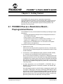
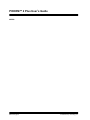
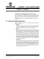
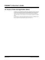
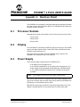
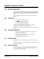
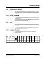
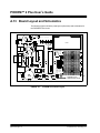
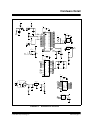
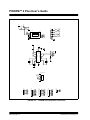
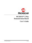
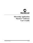
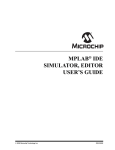
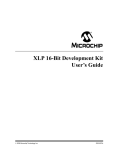
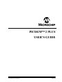
M PICDEM™ 2 PLUS USER’S GUIDE 2002 Microchip Technology Inc. DS51275A Note the following details of the code protection feature on PICmicro® MCUs. • • • • • • The PICmicro family meets the specifications contained in the Microchip Data Sheet. Microchip believes that its family of PICmicro microcontrollers is one of the most secure products of its kind on the market today, when used in the intended manner and under normal conditions. There are dishonest and possibly illegal methods used to breach the code protection feature. All of these methods, to our knowledge, require using the PICmicro microcontroller in a manner outside the operating specifications contained in the data sheet. The person doing so may be engaged in theft of intellectual property. Microchip is willing to work with the customer who is concerned about the integrity of their code. Neither Microchip nor any other semiconductor manufacturer can guarantee the security of their code. Code protection does not mean that we are guaranteeing the product as “unbreakable”. Code protection is constantly evolving. We at Microchip are committed to continuously improving the code protection features of our product. If you have any further questions about this matter, please contact the local sales office nearest to you. Information contained in this publication regarding device applications and the like is intended through suggestion only and may be superseded by updates. It is your responsibility to ensure that your application meets with your specifications. No representation or warranty is given and no liability is assumed by Microchip Technology Incorporated with respect to the accuracy or use of such information, or infringement of patents or other intellectual property rights arising from such use or otherwise. Use of Microchip’s products as critical components in life support systems is not authorized except with express written approval by Microchip. No licenses are conveyed, implicitly or otherwise, under any intellectual property rights. Trademarks The Microchip name and logo, the Microchip logo, FilterLab, KEELOQ, microID, MPLAB, PIC, PICmicro, PICMASTER, PICSTART, PRO MATE, SEEVAL and The Embedded Control Solutions Company are registered trademarks of Microchip Technology Incorporated in the U.S.A. and other countries. dsPIC, ECONOMONITOR, FanSense, FlexROM, fuzzyLAB, In-Circuit Serial Programming, ICSP, ICEPIC, microPort, Migratable Memory, MPASM, MPLIB, MPLINK, MPSIM, MXDEV, PICC, PICDEM, PICDEM.net, rfPIC, Select Mode and Total Endurance are trademarks of Microchip Technology Incorporated in the U.S.A. Serialized Quick Turn Programming (SQTP) is a service mark of Microchip Technology Incorporated in the U.S.A. All other trademarks mentioned herein are property of their respective companies. © 2002, Microchip Technology Incorporated, Printed in the U.S.A., All Rights Reserved. Printed on recycled paper. Microchip received QS-9000 quality system certification for its worldwide headquarters, design and wafer fabrication facilities in Chandler and Tempe, Arizona in July 1999 and Mountain View, California in March 2002. The Company’s quality system processes and procedures are QS-9000 compliant for its PICmicro® 8-bit MCUs, KEELOQ® code hopping devices, Serial EEPROMs, microperipherals, non-volatile memory and analog products. In addition, Microchip’s quality system for the design and manufacture of development systems is ISO 9001 certified. DS51275A - page ii 2002 Microchip Technology Inc. 12 PICDEM™ 2 PLUS USER’S GUIDE Table of Contents Chapter 1. Introduction 1.1 Welcome ......................................................................................... 1 1.2 PICDEM 2 Plus Demonstration Board ............................................ 2 1.3 Sample Devices .............................................................................. 3 1.4 Sample Programs ........................................................................... 3 1.5 PICDEM 2 Plus User’s Guide ......................................................... 4 1.6 Reference Documents .................................................................... 4 Chapter 2. Getting Started 2.1 PICDEM 2 Plus as a Stand-Alone Board – Preprogrammed Device .................................................................. 5 2.2 PICDEM 2 Plus Used with an In-Circuit Emulator or In-Circuit Debugger.......................................................................... 6 Chapter 3. Tutorials 3.1 Tutorial Program Operation ............................................................ 9 3.2 Source Code and Application Notes ............................................. 12 Appendix A. Hardware Detail A.1 Processor Sockets ........................................................................ 13 A.2 Display .......................................................................................... 13 A.3 Power Supply ................................................................................ 13 A.4 RS-232 Serial Port ........................................................................ 14 A.5 Switches ....................................................................................... 14 A.6 Oscillator Options ......................................................................... 14 A.7 Analog Input .................................................................................. 14 A.8 ICD Connector .............................................................................. 14 A.9 Temperature Sensor ..................................................................... 15 A.10 Serial EEPROM ............................................................................ 15 A.11 LCD ............................................................................................... 15 A.12 Sample Devices ............................................................................ 15 A.13 Board Layout and Schematics ...................................................... 16 2002 Microchip Technology Inc. DS51275A-page iii PICDEM™ 2 Plus User’s Guide Index ......................................................................................................... 19 Worldwide Sales and Service ................................................................. 20 DS51275A-page iv 2002 Microchip Technology Inc. 12 PICDEM™ 2 PLUS USER’S GUIDE Chapter 1. Introduction 1.1 Welcome Thank you for purchasing the PICDEM 2 Plus demonstration board from Microchip Technology Incorporated. The PICDEM 2 Plus is a simple board which demonstrates the capabilities of the 18-, 28- and 40-pin PIC16XXXX and PIC18XXXX devices. The PICDEM 2 Plus can be used stand-alone with a programmed part, with an in-circuit emulator (e.g., MPLAB® ICE) or with an in-circuit debugger (e.g., MPLAB ICD 2). Sample programs are provided to demonstrate the unique features of the supported devices. The PICDEM 2 Plus Kit comes with the following: 1. PICDEM 2 Plus Demonstration Board (Figure 1.1) 2. Sample devices 3. CD-ROM, which contains: a) Sample programs b) PICDEM 2 Plus Demonstration Board User’s Guide c) Application Notes If you are missing any part of the kit, please contact your nearest Microchip sales office, listed in the back of this publication, for help. 2002 Microchip Technology Inc. DS51275A-page 1 PICDEM™ 2 Plus User’s Guide 1.2 PICDEM 2 Plus Demonstration Board The PICDEM 2 Plus demonstration board has the following hardware features: 1. 18-, 28- and 40-pin DIP sockets. (Although 3 sockets are provided, only one device may be used at a time.) 2. On-board +5V regulator for direct input from 9V, 100mA AC/DC wall adapter or 9V battery, or hooks for a +5V, 100mA regulated DC supply. 3. RS-232 socket and associated hardware for direct connection to RS-232 interface. 4. In-circuit debugger (ICD) connector. 5. 5KΩ pot for devices with analog inputs. 6. Three push button switches for external stimulus and RESET. 7. Green power-on indicator LED. 8. Four red LEDs connected to PORTB. 9. Jumper J6 to disconnect LEDs from PORTB. 10. 4 MHz canned crystal oscillator. 11. Unpopulated holes provided for crystal connection. 12. 32.768 KHz crystal for Timer1 clock operation. 13. Jumper J7 to disconnect on-board RC oscillator (approximately 2 MHz). 14. 256K x 8 Serial EEPROM. 15. LCD display. 16. Piezo buzzer. 17. Prototype area for user hardware. 18. Microchip TC74 thermal sensor. DS51275A-page 2 2002 Microchip Technology Inc. Introduction 7 2 9 8 15 13 11 10 3 5 14 12 4 17 18 1 16 2 6 Figure 1.1: PICDEM 2 Plus Hardware 1.3 Sample Devices Two FLASH devices are included. The device types may change, but will generally include PIC16XXXX and PIC18XXXX 40-pin DIP devices. 1.4 Sample Programs The PICDEM 2 Plus Kit includes a CD-ROM with sample demonstration programs. These programs may be used with the included sample devices, with an in-circuit emulator (ICE) or with an in-circuit debugger (ICD). For each type of device (PIC16XXXX or PIC18XXXX), demo source code (several ASM files) and compiled code (one HEX file) are provided. 2002 Microchip Technology Inc. DS51275A-page 3 PICDEM™ 2 Plus User’s Guide 1.5 PICDEM 2 Plus User’s Guide This document describes the PICDEM 2 Plus demonstration board, tutorial and demonstration software. Detailed information on individual microcontrollers may be found in the device’s respective data sheet. Detailed information on in-circuit emulator (ICE) or in-circuit debugger (ICD) systems may be found in the respective tool’s user’s guide. Chapter 1: Introduction – This chapter introduces the PICDEM 2 Plus and provides a brief description of the hardware. Chapter 2: Getting Started – This chapter goes through a basic step-by-step process for getting your PICDEM 2 Plus up and running as a stand-alone board or with an ICE or ICD. Chapter 3: Tutorial – This chapter provides a detailed description of the tutorial program. Appendix A: Hardware Description: This appendix describes in detail the hardware of the PICDEM 2 Plus board. 1.6 Reference Documents Reference Documents may be obtained by contacting your nearest Microchip sales office (listed in the back of this document) or by downloading via the Microchip website (www.microchip.com). • Technical Library CD-ROM (DS00161) or individual data sheets: - PIC16F87X Data Sheet (DS30292) PIC18FXX2 Data Sheet (DS39564) PICmicro® Midrange MCU Family Reference Manual (DS33023) PICmicro® 18C MCU Family Reference Manual (DS39500) TC74 Data Sheet (DS21462) • MPLAB® IDE, Simulator and Editor User’s Guide (DS51025) • MPASM™ Assembler User’s Guide with MPLINK™ Linker and MPLIB™ Librarian (DS33014) • PRO MATE® II User’s Guide (DS30082) • PICSTART® Plus User’s Guide (DS51028) • MPLAB® ICE User’s Guide (DS51159) • MPLAB® ICD 2 Quick Start Guide (DS51268) • Microchip Third Party Guide (DS00104) DS51275A-page 4 2002 Microchip Technology Inc. 12 PICDEM™ 2 PLUS USER’S GUIDE Chapter 2. Getting Started The PICDEM 2 Plus may be used as a stand-alone board with a preprogrammed device, with an in-circuit emulator (ICE) or with an in-circuit debugger (ICD). For a list of PICmicro microcontroller-compatible ICEs or ICDs, please refer to the Development Systems Ordering Guide or the Microchip Third Party Guide. 2.1 PICDEM 2 Plus as a Stand-Alone Board – Preprogrammed Device The PICDEM 2 Plus may be demonstrated immediately by following the steps listed below: • Place the preprogrammed sample device in the appropriate socket on the PICDEM 2 Plus board. • Place a jumper on J6 (to enable the LEDs). • Verify that the board is set up for a 4MHz canned oscillator, (i.e., no jumper on J7; a 4MHz osc in Y2; Y1, C4 and C5 are empty). • Apply power to the PICDEM 2 Plus. For information on acceptable power sources, see Appendix A. To reprogram the sample device, the following will be necessary: 1. Program source code. User source code may be used to program the device or, if this has previously been done, the sample program may be restored from the file on the included CD-ROM. 2. An assembler, such as MPASM assembler (available with MPLAB IDE), or a compiler, such as MPLAB C18 (PIC18XXXX devices only). Source code must be assembled or compiled into a HEX file before it can be programmed into the device. Microchip Technology’s MPASM assmbler or MPLAB C18 C compiler may be used. Both are compatible with MPLAB IDE. However, other assemblers/compilers may be used. For a list of these PICmicro MCU-compatible language tools, please refer to the Microchip Third Party Guide. 3. A device programmer, such as PRO MATE II, PICSTART Plus, or MPLAB ICD 2 (programmer functionality available with MPLAB IDE v6.00 or greater). Once the sample program is in hex file format, a programmer may be used to program a Flash device. Microchip Technology’s PRO MATE II device programmer, PICSTART Plus development programmer or MPLAB ICD 2 may be used. All are compatible with MPLAB IDE. However, other programmers may be used. For a list of these PICmicro MCU-compatible programmers, please refer to the Microchip Third Party Guide. 2002 Microchip Technology Inc. DS51275A-page 5 PICDEM™ 2 Plus User’s Guide If the code protection bit(s) have not been programmed, the on-chip program memory can be read out for verification purposes. 2.2 PICDEM 2 Plus Used with an In-Circuit Emulator or In-Circuit Debugger To use PICDEM 2 Plus with an in-circuit emulator (ICE) or in-circuit debugger (ICD), refer to the tool’s user guide for instructions on how to power up and configure the ICE/ICD, as well as how to connect to target boards (e.g., Figure 2.1). Figure 2.1: PICDEM 2 Plus Connected to MPLAB ICD 2 using USB DS51275A-page 6 2002 Microchip Technology Inc. Getting Started Configure the PICDEM 2 Plus for the desired oscillator as described in Table 2.1. Refer to the ICE/ICD user’s guide for any oscillator configuration requirements. Table: 2.1 OSCILLATOR SELECTION Oscillator Selection on PICDEM 2 Plus 2002 Microchip Technology Inc. Modification on PICDEM 2 Plus RC J7 installed, Y2 empty, Y1 empty Crystal J7 removed, Y2 empty, crystal in Y1, caps in C4 and C5 Canned Oscillator J7 removed, oscillator in Y2 (Y1, C4, C5 empty) Resonator - no internal caps J7 removed, Y2 empty, resonator in Y1, caps in C4 and C5 Resonator - with internal caps J7 removed, Y2 empty, resonator in Y1, C4 and C5 empty DS51275A-page 7 PICDEM™ 2 Plus User’s Guide NOTES: DS51275A-page 8 2002 Microchip Technology Inc. 12 PICDEM™ 2 PLUS USER’S GUIDE Chapter 3. Tutorials The tutorial program is preprogrammed into the sample device, (i.e., p16demo.hex for a PIC16XXXX device and p18demo.hex for a PIC18XXXX device). Also, this program is on the included CD-ROM program disk for user reference, (i.e., if the sample device has been reprogrammed with another program, the tutorial may be reprogrammed into the device). For detailed information on the PICDEM 2 Plus hardware, please refer to Appendix A. 3.1 Tutorial Program Operation The tutorial program is made up of four components, which are individually displayed on the LCD. 1. Voltmeter This mode uses the A/D module to measure the voltage of the R16 pot and display a voltage between 0.00V and 5.00V on the LCD. Voltage is continually updated until the mode is exited by pressing RB0. 2. Buzzer This mode turns on the Piezo buzzer using the CCP1 module I/O pin RC2. The period and duty cycle of the CCP1 frequency can be changed while the buzzer is on. The changes in period and duty cycle are recognized immediately in the buzzer tone. To change the period and/or the duty cycle, press RB0 under the "Buzzer" menu. The buzzer will then sound off with default setting of 80h for the period and duty cycle. The cursor will flash over the periods first digit indicating that the PR2 register is ready to be incremented. To change the duty cycle, press RA4 once and the cursor will now flash over the duty cycle’s first digit indicating it is now ready to increment the CCPR1L register. The next press of RA4 will exit the buzzer function. 3. Temperature This mode uses a TC74 thermal sensor to measure ambient temperature in Celsius and then display that temperature on the LCD. Communication between the PICmicro MCU and sensor is accomplished using the MSSP module. This mode is exited by pressing RB0. This mode contains code that will write to the external on-board EEPROM. Every 2 seconds the code will write to a defined EEPROM address and store the current temperature in that address. 2002 Microchip Technology Inc. DS51275A-page 9 PICDEM™ 2 Plus User’s Guide 4. Clock Once this mode is entered from the main menu, a real time clock will start counting from 00:00:00. The Timer1 module and a 32KHz clock crystal is used to establish a real time clock. By pressing RA4, the clock time can be set to the user’s preference. When RA4 is pressed to set the time, the cursor will flash over the hours ten digit. Press RA4 again and the cursor will now flash over the minutes ten digit. RB0 is used to increment hours and minutes whenever the cursor is flashing over either. After the minutes have been set, press RA4 and the time will be set and the LCD is returned to an active clock display. The data that is sent to the LCD is also sent to the RS-232 serial port using the USART on the PICmicro MCU. A HyperTerminal™ program on the PC will be able to display the same information that is displayed on the LCD DS51275A-page 10 2002 Microchip Technology Inc. Tutorials . Power-up PICDEM™ 2 Plus Voltmeter RA4=Next RB0=Now Volts=0.33V RB0=Exit Buzzer RA4=Next RB0=Now Prd=128 DC=128 RA4=-> RB0=++ Temperature RA4=Next RB0=Now RA4 = 3 presses Temp=022C RB0=Exit Clock RA4=Next RB0=Now 00.00.02 RA4=Set RB0=Menu 00.00.03 RA4=-> RB0=++ RA4 = 3 presses Figure 3.1: Tutorial Program Flow Chart 2002 Microchip Technology Inc. DS51275A-page 11 PICDEM™ 2 Plus User’s Guide 3.2 Source Code and Application Notes In addition to the assembled tutorial programs (HEX files), source code used to create these HEX files is included on the PICDEM 2 Plus CD-ROM. Both source code and related HEX file are found in device-specific directories. Application Notes are also included on the CD-ROM for additional examples of use. For information on how to reprogram the device with new or modified code, or how to restore the tutorial program, please see Section 2.1. DS51275A-page 12 2002 Microchip Technology Inc. 12 PICDEM™ 2 PLUS USER’S GUIDE Appendix A. Hardware Detail The PICDEM 2 Plus hardware is extremely simple and is intended to illustrate the ease of use of various PICmicro MCUs. The PICDEM 2 Plus features the following hardware elements: A.1 Processor Sockets Although three sockets are provided, only one device may be used at a time. • 18-pin socket • 28-pin socket • 40-pin socket A.2 Display Four red LEDs are connected to PORTB of each processor type. The PORTB pins are set high to light the LEDs. These LEDs may be disconnected from PORTB by removing jumper J6. One green LED is provided to determine whether there is power to the PICDEM 2 Plus board (LED on) or not (LED off). A.3 Power Supply There are three ways to supply power to PICDEM 2 Plus: • A 9V battery can be plugged into J8. • A 9V, 100mA unregulated AC or DC supply can be plugged into J2. A power supply can be purchased through Microchip, Part #AC162039. • A +5V, 100mA regulated DC supply can be connected to the hooks provided. Note: The PICDEM 2 Plus kit does not include a power supply. MPLAB ICE 2000 users have a regulated +5V power supply available in the logic probe connector and can easily connect to the hooks on PICDEM 2 Plus (Red probe to +5V and Black probe to GND). MPLAB ICD 2 users may use the ICD to power the target board to 5V, up to 200mA, if the MPLAB ICD 2 is connected to the PC with a serial cable. 2002 Microchip Technology Inc. DS51275A-page 13 PICDEM™ 2 Plus User’s Guide A.4 RS-232 Serial Port An RS-232 level shifting IC has been provided with all necessary hardware to support connection of an RS-232 host through the DB9 connector. The port is configured as DCE, and can be connected to a PC using a straight through cable. The PIC16/PIC18 RX and TX pins are tied to the RX and TX lines of the MAX232A. A.5 Switches Three switches provide the following functions: • S1 - MCLR to hard reset the processor • S2 - Active low switch connected to RA4 • S3 - Active low switch connected to RB0 Switches S1 and S3 have debounce capacitors whereas S2 does not, allowing the user to investigate debounce techniques. When pressed, the switches are grounded. When idle, they are pulled high (+5V). A.6 Oscillator Options • RC oscillator (2MHz approximately) supplied. This oscillator may be disabled by removing jumper J7. • Pads provided for user furnished crystal and two capacitors. • Removable 4 MHz canned oscillator. • 32.768 KHz (watch type) crystal for Timer1. A.7 Analog Input A 5K ohm potentiometer is connected through a series 470 ohm resistor to AN0. The pot can be adjusted from VDD to GND to provide an analog input to the parts with an A/D module. A.8 ICD Connector By way of the modular connector (J5), the MPLAB ICD 2 can be connected for low cost debugging. The ICD connector utilizes RB6 and RB7 of the microcontroller for in-circuit debugging. DS51275A-page 14 2002 Microchip Technology Inc. Hardware Detail A.9 Temperature Sensor This is a serial digital thermal sensor (TC74) connected to the 28- and 40- pin microcontrollers via RC3 and RC4. Communication is accomplished with the TC74 via its 2-wire I2C™ compatible serial port. This device has an address of 1001101b. A.10 Serial EEPROM A 24L256 256K (256Kx8) serial EEPROM is included on the board to illustrate I2C bus concepts. For more information on the serial EEPROM, please refer to the most recent version of the Technical Library CD-ROM. A.11 LCD An LCD display with 2 lines, 16 characters each, is connected to the 28- and 40-pin sockets. There are three control lines (RA3: RA1) and four data lines (RD3: RD0). A 5K pot may be installed into R20 to adjust contrast on the LCD. If this is done, R5 and R6 need to be removed. A.12 Sample Devices A sample part programmed with a simple program is included in the PICDEM 2 Plus kits. Table 10-1 lists the I/O features and port connections for each processor type. TABLE A-1: PORT CONNECTIONS LEDs RS-232 S1 S2 S3 Pot R16 LCD 18-pin RB3:RB0 N/A MCLR RA4 RB0 RA0 N/A 28-pin RB3:RB0 RC6/RC7 MCLR RA4 RB0 RA0 40-pin RB3:RB0 RC6/RC7 MCLR RA4 RB0 RA0 Device 2002 Microchip Technology Inc. ICD Temp Sensor Y1/Y2 N/A RB6/RB7 N/A Yes RA3:RA1 RC3/RC4 RD3:RD0 RC2 RB6/RB7 RC3/RC4 Yes RA3:RS1 RC3/RC4 RD3:RD0 RC2 RB6/RB7 RC3/RC4 Yes EEPROM Buzzer N/A DS51275A-page 15 PICDEM™ 2 Plus User’s Guide A.13 Board Layout and Schematics The following figures show the parts layout (silkscreen) and schematics for the PICDEM 2 Plus board. J8 RB3 RB2 RB1 RB0 PWR ( ) J6 ( ) ( ) ( ) ( ) +9V IN U8 C18 C4 R21 R22 R24 R4 LCD1 R6 R5 C16 J2 R23 D1 R15 5V BATTERY CR1 CR2 Y2 J7 R20 C3 Y1 28 PIN 40 PIN RB0 S2 S3 R7 RA4 C9 R17 R1 S1 FIGURE A-1: DS51275A-page 16 R18 RESET R3 R10 C1 R11 1 P1 +5V +5V GND +5V C6 C7 U5 +5V M GND J9 C20 C14 R9 R8 Y3 0 1 2 0 1 2 3 4 5 6 7 C2 0 1 2 3 4 5 C8 18 PIN R19 RA PORT RB PORT RC PORT RD PORT RS-232 C13 C15 U4 J5 Q1 RE PORT C19 R16 U3 ICD RA0 GND 1 +5V C10 C11 U1 1 GND 1 R2 R14 C5 C17 C12 J1 CONTRAST U2 U6 GND PICDEM 2 PLUS DEMO BOARD ©2002 PICDEM 2 Plus Parts Layout 2002 Microchip Technology Inc. Hardware Detail +5V +5V R1 10K R7 47K 1 2 R19 470 +5V S1 S3 1 2 4 3 4 3 C2 0.1uF C1 C9 U1 0.1uF 0.1uF 11 VDD 12 VDD +5V R17 RB0 R2 R16 5K NMCLR 1 R18 470 R3 4.7K S2 1 2 2 3 4 5 6 7 33 34 35 36 37 38 39 40 RA0 RA1 RA2 RA3 RA4 RA5 RB0 RB1 RB2 RB3 RB4 RB5 RB6 RB7 470 +5V MCLR 470 4 3 +5V RA0 RA1 RA2 RA3 RA4 RA5 RB0 RB1 RB2 RB3 RB4 RB5 RB6 RB7 RE2 RE1 RE0 RD7 RD6 RD5 RD4 RD3 RD2 RD1 RD0 RC7 RC6 RC5 RC4 RC3 RC2 RC1 RC0 OSC2 12 VSS 31 VSS P1 PIEZO_BUZ 10 9 8 30 29 28 27 22 21 20 10 26 25 24 23 18 17 16 15 14 RE2 RE1 RE0 RD7 RD6 RD5 RD4 RD3 RD2 RD1 RD0 RX TX RC5 SDA SCL RC2 OSI OSO +5V C10 0.1uF +5V U4 R8 4.7K 8 Vcc 7 WP 6 SCL 5 SDA R9 4.7K 1 2 3 4 A0 A1 A2 GND 24LC256_DIP +5V Y2 4 1 NC/OE VCC 3 2 GND OUT OSC2 DSC1 13 OSC1 TBD Y1 OSC1 40-PIN DEVICE TBD +5V 3 J9 R11 RC2 Q1 2N2222 TO-92 2 2.2K +5V C4 0.7 C8 1 C5 0.7 R4 4.7K J7 0.1uF U2 20 NMCLR RA0 RA1 RA2 RA3 RA4 RA5 1 MCLR 2 3 4 5 6 7 RA0 RA1 RA2 RA3 RA4 RA5 8 DSC1 9 DSC2 VDD DSC1 DSC2 RB0 RB1 RB2 RB3 RB4 RB5 RB6 RB7 21 22 23 24 25 26 27 28 RC0 RC1 RC2 RC3 RC4 RC5 RC6 RC7 11 12 13 14 15 16 17 18 C3 22pF Y3 RB0 RB1 RB2 RB3 RB4 RB5 RB6 RB7 32.768KHz C6 22pF C7 22pF OSO OSI RC2 SCL SDA RC2 TX RX VSS VSS +5V 28-PIN DEVICE C19 0.1uF U6 1 2 3 CR1 +5V LM340T-5.0 U8 1 3 IN OUT C16 0.1 COM J2 DJ005B CR2 1N914 + 2 C17 220 + C18 220 R15 470 14 VDD 4 MCLR 6 17 RB0/IN1 RA0 7 18 RA1 RB1 8 1 RA2 RB2 9 2 RA3 RB3 10 3 RA4/TOCK1 RB4 11 RB5 16 OSC1/CLKIN 12 RB6 15 13 OSC2/CLKOUT RB7 5 VSS NMCLR RA0 RA1 RA2 RA3 RA4 OSC1 OSC2 D1 J8 RB0 RB1 RB2 RB3 RB4 RB5 RB6 RB7 18-PIN DEVICE 9V +5V U5 1 SDA SCL ND VDD 2 SDA 4 SCL GND 5 3 TC74_TO-220_5P FIGURE A-2: 2002 Microchip Technology Inc. C20 0.1 PICDEM 2 Plus Schematic DS51275A-page 17 PICDEM™ 2 Plus User’s Guide +5V R20 10K R5 R6 10K 300 LCD1 3 2 1 14 13 12 15 RA1 RA2 RA3 +5V 4 5 6 7 8 9 10 11 DB0 DB1 DB2 DB3 DB4 DB5 DB6 DB7 E R/W RS VEE VCC GND GND1 RO0 RO1 RO2 RO3 02 R21 470 03 R22 470 04 R23 470 05 R24 470 RB0 RB1 RB2 RB3 J6 +5V +5V C11 C12 0.1 11 T1IN 10 T2IN T2OUT 3 C1+ C2+ C1- C2- 6 V- 1 2 3 4 5 14 7 13 A1IN 8 A2IN 12 A1OUT 9 A2OUT 1 15 C13 0.1 T1OUT J1 6 7 8 9 DE9S-FRS 4 R14 10.0 5 C15 GND RX V+ VDC 2 TX 16 0.1uF U3 0.1 M^ C14 0.1 ICD CONNECTOR +5V J5 1 2 3 4 5 6 NMCLR RB7 RB6 RA RB 1 2 3 4 5 6 RA0 RA1 RA2 RA3 RA4 RA5 1 2 3 4 5 6 7 8 RC RB0 RB1 RB2 RB3 RB4 RB5 RB6 RB7 FIGURE A-3: DS51275A-page 18 1 2 3 4 5 6 7 8 [RC0] [RC1] [RC3] [RC4] [RC6] [RC7] RD OSO OSI RC2 SCL SDA RC5 TX RX 1 2 3 4 5 6 7 8 RE RD0 RD1 RD2 RD3 RD4 RD5 RD6 RD7 1 2 3 RE0 RE1 RE2 PICDEM 2 Plus Schematic (Continued) 2002 Microchip Technology Inc. 12 PICDEM 2 PLUS USER’S GUIDE Index A A/D Input .................................................... 2, 14 B Board .................................................. 1, 2, 5, 13 Parts Layout ............................................. 16 Power Supply ....................................... 5, 13 Silkscreen ................................................ 16 Buzzer .............................................................. 9 Buzzer, Piezo ................................................... 2 C Clock .............................................................. 10 D Demonstation Board. See Board Demonstation Programs. See Sample Programs E EEPROM, Serial ......................................... 2, 15 H Hardware ........................................................ 13 K Kit Components ................................................ 1 L LCD ............................................................ 2, 15 LEDs Green Power ........................................ 2, 13 Red Display ...................................... 2, 5, 13 M MPASM Assembler .......................................... 5 MPASM Assembler User’s Guide with MPLINK Linker and MPLIB Librarian .. 4 MPLAB C18 ...................................................... 5 MPLAB ICD 2 ............................... 1, 5, 6, 13, 14 MPLAB ICD 2 Quick Start Guide ...................... 4 MPLAB ICE ............................................ 1, 6, 13 MPLAB ICE User’s Guide ................................ 4 MPLAB IDE ...................................................... 5 MPLAB IDE User’s Guide ................................ 4 2002 Microchip Technology Inc. O Oscillator Options ........................................... 14 Oscillator Selection ........................................... 7 P PIC16F87x Data Sheet ..................................... 4 PIC16XXXX ...................................................... 1 Tutorial Program ........................................ 9 PIC18Fxx2 Data Sheet ..................................... 4 PIC18XXXX ...................................................... 1 Tutorial Program ........................................ 9 PICDEM 2 Plus Board. See Board PICDEM 2 Plus Kit. See Kit Components PICSTART® Plus ............................................. 5 PICSTART® Plus User’s Guide ....................... 4 Piezo Buzzer ..................................................... 2 PRO MATE® II ................................................. 5 PRO MATE® II User’s Guide ........................... 4 Pushbuttons. See Switches R Reference Documents ...................................... 4 RS-232 ........................................................ 2, 14 S Sample Devices ...................................... 1, 3, 15 Sample Programs ......................................... 1, 3 Sockets ........................................................... 13 Switches ..................................................... 2, 14 T TC74 ........................................................... 2, 15 TC74 Data Sheet .............................................. 4 Temperature ..................................................... 9 Tutorial .............................................................. 9 V Voltmeter .......................................................... 9 DS51275A-page 19 M WORLDWIDE SALES AND SERVICE AMERICAS ASIA/PACIFIC Japan Corporate Office Australia 2355 West Chandler Blvd. Chandler, AZ 85224-6199 Tel: 480-792-7200 Fax: 480-792-7277 Technical Support: 480-792-7627 Web Address: http://www.microchip.com Microchip Technology Australia Pty Ltd Suite 22, 41 Rawson Street Epping 2121, NSW Australia Tel: 61-2-9868-6733 Fax: 61-2-9868-6755 Microchip Technology Japan K.K. Benex S-1 6F 3-18-20, Shinyokohama Kohoku-Ku, Yokohama-shi Kanagawa, 222-0033, Japan Tel: 81-45-471- 6166 Fax: 81-45-471-6122 Rocky Mountain China - Beijing 2355 West Chandler Blvd. Chandler, AZ 85224-6199 Tel: 480-792-7966 Fax: 480-792-7456 Microchip Technology Consulting (Shanghai) Co., Ltd., Beijing Liaison Office Unit 915 Bei Hai Wan Tai Bldg. No. 6 Chaoyangmen Beidajie Beijing, 100027, No. China Tel: 86-10-85282100 Fax: 86-10-85282104 Atlanta 500 Sugar Mill Road, Suite 200B Atlanta, GA 30350 Tel: 770-640-0034 Fax: 770-640-0307 Boston 2 Lan Drive, Suite 120 Westford, MA 01886 Tel: 978-692-3848 Fax: 978-692-3821 Chicago 333 Pierce Road, Suite 180 Itasca, IL 60143 Tel: 630-285-0071 Fax: 630-285-0075 Dallas 4570 Westgrove Drive, Suite 160 Addison, TX 75001 Tel: 972-818-7423 Fax: 972-818-2924 Detroit Tri-Atria Office Building 32255 Northwestern Highway, Suite 190 Farmington Hills, MI 48334 Tel: 248-538-2250 Fax: 248-538-2260 Kokomo 2767 S. Albright Road Kokomo, Indiana 46902 Tel: 765-864-8360 Fax: 765-864-8387 Los Angeles 18201 Von Karman, Suite 1090 Irvine, CA 92612 Tel: 949-263-1888 Fax: 949-263-1338 China - Chengdu Microchip Technology Consulting (Shanghai) Co., Ltd., Chengdu Liaison Office Rm. 2401, 24th Floor, Ming Xing Financial Tower No. 88 TIDU Street Chengdu 610016, China Tel: 86-28-6766200 Fax: 86-28-6766599 China - Fuzhou Microchip Technology Consulting (Shanghai) Co., Ltd., Fuzhou Liaison Office Unit 28F, World Trade Plaza No. 71 Wusi Road Fuzhou 350001, China Tel: 86-591-7503506 Fax: 86-591-7503521 China - Shanghai Microchip Technology Consulting (Shanghai) Co., Ltd. Room 701, Bldg. B Far East International Plaza No. 317 Xian Xia Road Shanghai, 200051 Tel: 86-21-6275-5700 Fax: 86-21-6275-5060 China - Shenzhen 150 Motor Parkway, Suite 202 Hauppauge, NY 11788 Tel: 631-273-5305 Fax: 631-273-5335 Microchip Technology Consulting (Shanghai) Co., Ltd., Shenzhen Liaison Office Rm. 1315, 13/F, Shenzhen Kerry Centre, Renminnan Lu Shenzhen 518001, China Tel: 86-755-2350361 Fax: 86-755-2366086 San Jose Hong Kong Microchip Technology Inc. 2107 North First Street, Suite 590 San Jose, CA 95131 Tel: 408-436-7950 Fax: 408-436-7955 Microchip Technology Hongkong Ltd. Unit 901-6, Tower 2, Metroplaza 223 Hing Fong Road Kwai Fong, N.T., Hong Kong Tel: 852-2401-1200 Fax: 852-2401-3431 New York Toronto 6285 Northam Drive, Suite 108 Mississauga, Ontario L4V 1X5, Canada Tel: 905-673-0699 Fax: 905-673-6509 India Microchip Technology Inc. India Liaison Office Divyasree Chambers 1 Floor, Wing A (A3/A4) No. 11, O’Shaugnessey Road Bangalore, 560 025, India Tel: 91-80-2290061 Fax: 91-80-2290062 Korea Microchip Technology Korea 168-1, Youngbo Bldg. 3 Floor Samsung-Dong, Kangnam-Ku Seoul, Korea 135-882 Tel: 82-2-554-7200 Fax: 82-2-558-5934 Singapore Microchip Technology Singapore Pte Ltd. 200 Middle Road #07-02 Prime Centre Singapore, 188980 Tel: 65-6334-8870 Fax: 65-6334-8850 Taiwan Microchip Technology Taiwan 11F-3, No. 207 Tung Hua North Road Taipei, 105, Taiwan Tel: 886-2-2717-7175 Fax: 886-2-2545-0139 EUROPE Denmark Microchip Technology Nordic ApS Regus Business Centre Lautrup hoj 1-3 Ballerup DK-2750 Denmark Tel: 45 4420 9895 Fax: 45 4420 9910 France Microchip Technology SARL Parc d’Activite du Moulin de Massy 43 Rue du Saule Trapu Batiment A - ler Etage 91300 Massy, France Tel: 33-1-69-53-63-20 Fax: 33-1-69-30-90-79 Germany Microchip Technology GmbH Gustav-Heinemann Ring 125 D-81739 Munich, Germany Tel: 49-89-627-144 0 Fax: 49-89-627-144-44 Italy Microchip Technology SRL Centro Direzionale Colleoni Palazzo Taurus 1 V. Le Colleoni 1 20041 Agrate Brianza Milan, Italy Tel: 39-039-65791-1 Fax: 39-039-6899883 United Kingdom Arizona Microchip Technology Ltd. 505 Eskdale Road Winnersh Triangle Wokingham Berkshire, England RG41 5TU Tel: 44 118 921 5869 Fax: 44-118 921-5820 03/01/02 '"$"' DS51275A-page 20 2002 Microchip Technology Inc.