1
TPS150
Twisted Pair A/V Switching and Transmission System
68-958-01 Rev. B
Printed in USA
10 04
Precautions
Safety Instructions • English
This symbol is intended to alert the user of important operating and maintenance
(servicing) instructions in the literature provided with the equipment.
This symbol is intended to alert the user of the presence of uninsulated dangerous
voltage within the product's enclosure that may present a risk of electric shock.
Warning
Power sources • This equipment should be operated only from the power source indicated on the
product. This equipment is intended to be used with a main power system with a grounded
(neutral) conductor. The third (grounding) pin is a safety feature, do not attempt to bypass or
disable it.
Caution
Power disconnection • To remove power from the equipment safely, remove all power cords from
the rear of the equipment, or the desktop power module (if detachable), or from the power
source receptacle (wall plug).
Read Instructions • Read and understand all safety and operating instructions before using the
equipment.
Power cord protection • Power cords should be routed so that they are not likely to be stepped on or
pinched by items placed upon or against them.
Retain Instructions • The safety instructions should be kept for future reference.
Servicing • Refer all servicing to qualified service personnel. There are no user-serviceable parts
inside. To prevent the risk of shock, do not attempt to service this equipment yourself because
opening or removing covers may expose you to dangerous voltage or other hazards.
Follow Warnings • Follow all warnings and instructions marked on the equipment or in the user
information.
Avoid Attachments • Do not use tools or attachments that are not recommended by the equipment
manufacturer because they may be hazardous.
Slots and openings • If the equipment has slots or holes in the enclosure, these are provided to
prevent overheating of sensitive components inside. These openings must never be blocked by
other objects.
Lithium battery • There is a danger of explosion if battery is incorrectly replaced. Replace it only
with the same or equivalent type recommended by the manufacturer. Dispose of used batteries
according to the manufacturer's instructions.
Consignes de Sécurité • Français
Avertissement
Ce symbole sert à avertir l’utilisateur que la documentation fournie avec le matériel
contient des instructions importantes concernant l’exploitation et la maintenance
(réparation).
Alimentations• Ne faire fonctionner ce matériel qu’avec la source d’alimentation indiquée sur
l’appareil. Ce matériel doit être utilisé avec une alimentation principale comportant un fil de
terre (neutre). Le troisième contact (de mise à la terre) constitue un dispositif de sécurité :
n’essayez pas de la contourner ni de la désactiver.
Ce symbole sert à avertir l’utilisateur de la présence dans le boîtier de l’appareil de
tensions dangereuses non isolées posant des risques d’électrocution.
Déconnexion de l’alimentation• Pour mettre le matériel hors tension sans danger, déconnectez tous
les cordons d’alimentation de l’arrière de l’appareil ou du module d’alimentation de bureau (s’il
est amovible) ou encore de la prise secteur.
Attention
Lire les instructions• Prendre connaissance de toutes les consignes de sécurité et d’exploitation avant
d’utiliser le matériel.
Conserver les instructions• Ranger les consignes de sécurité afin de pouvoir les consulter à l’avenir.
Respecter les avertissements • Observer tous les avertissements et consignes marqués sur le matériel ou
présentés dans la documentation utilisateur.
Eviter les pièces de fixation • Ne pas utiliser de pièces de fixation ni d’outils non recommandés par le
fabricant du matériel car cela risquerait de poser certains dangers.
Protection du cordon d’alimentation • Acheminer les cordons d’alimentation de manière à ce que
personne ne risque de marcher dessus et à ce qu’ils ne soient pas écrasés ou pincés par des
objets.
Réparation-maintenance • Faire exécuter toutes les interventions de réparation-maintenance par un
technicien qualifié. Aucun des éléments internes ne peut être réparé par l’utilisateur. Afin
d’éviter tout danger d’électrocution, l’utilisateur ne doit pas essayer de procéder lui-même à ces
opérations car l’ouverture ou le retrait des couvercles risquent de l’exposer à de hautes tensions
et autres dangers.
Fentes et orifices • Si le boîtier de l’appareil comporte des fentes ou des orifices, ceux-ci servent à
empêcher les composants internes sensibles de surchauffer. Ces ouvertures ne doivent jamais
être bloquées par des objets.
Lithium Batterie • Il a danger d'explosion s'll y a remplacment incorrect de la batterie. Remplacer
uniquement avec une batterie du meme type ou d'un ype equivalent recommande par le
constructeur. Mettre au reut les batteries usagees conformement aux instructions du fabricant.
Sicherheitsanleitungen • Deutsch
Vorsicht
Dieses Symbol soll dem Benutzer in der im Lieferumfang enthaltenen
Dokumentation besonders wichtige Hinweise zur Bedienung und Wartung
(Instandhaltung) geben.
Stromquellen • Dieses Gerät sollte nur über die auf dem Produkt angegebene Stromquelle betrieben
werden. Dieses Gerät wurde für eine Verwendung mit einer Hauptstromleitung mit einem
geerdeten (neutralen) Leiter konzipiert. Der dritte Kontakt ist für einen Erdanschluß, und stellt
eine Sicherheitsfunktion dar. Diese sollte nicht umgangen oder außer Betrieb gesetzt werden.
Dieses Symbol soll den Benutzer darauf aufmerksam machen, daß im Inneren des
Gehäuses dieses Produktes gefährliche Spannungen, die nicht isoliert sind und
die einen elektrischen Schock verursachen können, herrschen.
Stromunterbrechung • Um das Gerät auf sichere Weise vom Netz zu trennen, sollten Sie alle
Netzkabel aus der Rückseite des Gerätes, aus der externen Stomversorgung (falls dies möglich
ist) oder aus der Wandsteckdose ziehen.
Achtung
Lesen der Anleitungen • Bevor Sie das Gerät zum ersten Mal verwenden, sollten Sie alle Sicherheits-und
Bedienungsanleitungen genau durchlesen und verstehen.
Aufbewahren der Anleitungen • Die Hinweise zur elektrischen Sicherheit des Produktes sollten Sie
aufbewahren, damit Sie im Bedarfsfall darauf zurückgreifen können.
Befolgen der Warnhinweise • Befolgen Sie alle Warnhinweise und Anleitungen auf dem Gerät oder in
der Benutzerdokumentation.
Keine Zusatzgeräte • Verwenden Sie keine Werkzeuge oder Zusatzgeräte, die nicht ausdrücklich vom
Hersteller empfohlen wurden, da diese eine Gefahrenquelle darstellen können.
Instrucciones de seguridad • Español
Schutz des Netzkabels • Netzkabel sollten stets so verlegt werden, daß sie nicht im Weg liegen und
niemand darauf treten kann oder Objekte darauf- oder unmittelbar dagegengestellt werden
können.
Wartung • Alle Wartungsmaßnahmen sollten nur von qualifiziertem Servicepersonal durchgeführt
werden. Die internen Komponenten des Gerätes sind wartungsfrei. Zur Vermeidung eines
elektrischen Schocks versuchen Sie in keinem Fall, dieses Gerät selbst öffnen, da beim Entfernen
der Abdeckungen die Gefahr eines elektrischen Schlags und/oder andere Gefahren bestehen.
Schlitze und Öffnungen • Wenn das Gerät Schlitze oder Löcher im Gehäuse aufweist, dienen diese
zur Vermeidung einer Überhitzung der empfindlichen Teile im Inneren. Diese Öffnungen dürfen
niemals von anderen Objekten blockiert werden.
Litium-Batterie • Explosionsgefahr, falls die Batterie nicht richtig ersetzt wird. Ersetzen Sie
verbrauchte Batterien nur durch den gleichen oder einen vergleichbaren Batterietyp, der auch
vom Hersteller empfohlen wird. Entsorgen Sie verbrauchte Batterien bitte gemäß den
Herstelleranweisungen.
Advertencia
Este símbolo se utiliza para advertir al usuario sobre instrucciones importantes de
operación y mantenimiento (o cambio de partes) que se desean destacar en el
contenido de la documentación suministrada con los equipos.
Alimentación eléctrica • Este equipo debe conectarse únicamente a la fuente/tipo de alimentación
eléctrica indicada en el mismo. La alimentación eléctrica de este equipo debe provenir de un
sistema de distribución general con conductor neutro a tierra. La tercera pata (puesta a tierra) es
una medida de seguridad, no puentearia ni eliminaria.
Este símbolo se utiliza para advertir al usuario sobre la presencia de elementos con
voltaje peligroso sin protección aislante, que puedan encontrarse dentro de la caja
o alojamiento del producto, y que puedan representar riesgo de electrocución.
Desconexión de alimentación eléctrica • Para desconectar con seguridad la acometida de
alimentación eléctrica al equipo, desenchufar todos los cables de alimentación en el panel trasero
del equipo, o desenchufar el módulo de alimentación (si fuera independiente), o desenchufar el
cable del receptáculo de la pared.
Precaucion
Leer las instrucciones • Leer y analizar todas las instrucciones de operación y seguridad, antes de usar
el equipo.
Conservar las instrucciones • Conservar las instrucciones de seguridad para futura consulta.
Obedecer las advertencias • Todas las advertencias e instrucciones marcadas en el equipo o en la
documentación del usuario, deben ser obedecidas.
Evitar el uso de accesorios • No usar herramientas o accesorios que no sean especificamente
recomendados por el fabricante, ya que podrian implicar riesgos.
Protección del cables de alimentación • Los cables de alimentación eléctrica se deben instalar en
lugares donde no sean pisados ni apretados por objetos que se puedan apoyar sobre ellos.
Reparaciones/mantenimiento • Solicitar siempre los servicios técnicos de personal calificado. En el
interior no hay partes a las que el usuario deba acceder. Para evitar riesgo de electrocución, no
intentar personalmente la reparación/mantenimiento de este equipo, ya que al abrir o extraer las
tapas puede quedar expuesto a voltajes peligrosos u otros riesgos.
Ranuras y aberturas • Si el equipo posee ranuras o orificios en su caja/alojamiento, es para evitar el
sobrecalientamiento de componentes internos sensibles. Estas aberturas nunca se deben obstruir
con otros objetos.
Batería de litio • Existe riesgo de explosión si esta batería se coloca en la posición incorrecta. Cambiar
esta batería únicamente con el mismo tipo (o su equivalente) recomendado por el fabricante.
Desachar las baterías usadas siguiendo las instrucciones del fabricante.
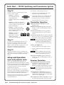
Quick Start — TPS150 Switching
and Transmission System
Installation
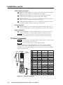
Step 7
Connect a host device, such as a computer or
touch panel control, to the transmitter via this
9-pin D connector and a null modem serial
port cable for serial RS-232 control.
Step 1
Turn off power to the input and output devices,
and remove the power cords from them.
Step 2
If desired, mount the TPT150 transmitter in a
rack.
5
1
Step 3
If desired, mount the TPR150 receiver using the
included projector bracket.
9
6
Female
Step 4
Connect source video devices to the transmitter’s
inputs.
If desired, connect a
monitor to the Input 1 Local Monitor
connector.
R-Y
VIDEO
S-VIDEO
Y
B-Y
Step 5
Connect audio devices to the input 1
through input 4 left and right RCA
connectors.
L
Connect an audio device, such as powered
speakers, to this 3.8 mm, 5-pole captive screw
connector for balanced or unbalanced audio
output.
Tip
Ring
Sleeve (s)
Tip
Ring
Balanced Output
CONTACT
CLOSURE
GND
PROJ PWR
VOL DN
VOL UP
IN4
IN3
IN2
IN1
Step 9
Connect a shielded twisted pair (STP) cable or
foil shielded pair (FTP) with RJ-45 connectors
between the transmitter and receiver. Ensure
that both ends of the cable are terminated using
the same protocol, either TIA/EIA 568 A or 568 B.
Extron recommends STP or FTP cable
only.
R
Step 6
Unbalanced Output
Connect an optional CTP150CM
control panel module or other
contact closure device to this 8-pin
3.5 mm captive screw connector.
See chapter 2, Installation.
To make your own contact closure
device, wire the connector as
shown at right. To issue a
command, momentarily short the
appropriate pin to ground.
For proper
system operation, connect only one video
format to input 3 and input 4.
Tip
See caution
Sleeve
Tip
See caution
Function
Not used
Receive data
Transmit data
Not used
Signal ground
Not used
Not used
Not used
Not used
Step 8
Inputs 1 and 2 — Connect
two RGB video sources.
Inputs 3 and 4 —
Connect either
component video,
S-video, or
composite video
sources.
Connected
TPS150 RS-232
pin device pin
—
1
RX
2
TX
3
—
4
Gnd
5
—
6
—
7
—
8
—
9
Side
Clip Down
RJ-45
connector
Pin
CAUTION Connect the
sleeve to ground.
Connecting the
sleeve to a
negative (-)
terminal will
damage the audio
output circuits.
12345678
1&2
568 B
Wire color
1
White-green
White-orange
2
Green
Orange
3
White-orange White-green
4
Blue
5
White-blue
White-blue
6
Orange
Green
Blue
7
White-brown
White-brown
8
Brown
Brown
7&8
3&6 4&5
568 A
Wire color
Twisted
Pairs
TPS150 Switching and Transmission System • Quick Start
QS-1
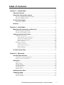
Quick Start — TPS150 Switching and Transmission System
Step 10
See chapter 4, Serial Communications, to:
Connect a projector or plasma display to the
receiver’s video outputs.
• Program a serial command to each of the
transmitter’s Input Select buttons.
Output 1 — Connect a
VGA cable between the
15-pin HD female
connector and the VGA or RGB input on the
display.
• Program projector power on and power off
commands to the Projector Power button.
Output 2 — Connect a composite
video cable between this BNC female
connector and the composite video
input on the display.
Transmitter Operation
Output 3 — Connect an S-video
cable between this 4-pin mini DIN
female connector and the S-video
input on the display.
Blank button and LED toggle the video mute
function on and off and identify the mute on
or off status.
Output 4 — Connect a
cable between these
BNC female connectors
R-Y
and the component
video input on the display.
• Set the projector power timeout function.
• Program the projector power delays.
Input Select buttons and LEDs select and
identify inputs.
Projector Power button, when programmed,
commands the projector to power itself on
and off.
Y
B-Y
Projector Power LED, when lit, indicates that the
projector power is on. The LED blinks during
the power on and off delay (if programmed).
Some projectors use the same command
for power on and off. If the same code is
specified for on and off, the Projector
Power LED blinks for each button push.
Step 11
Connect a serial cable between the receiver’s
RS-232 Port connector and the serial control
connector on the display for control of the
display. See the drawing on page QS-1 to wire
the connector for RS-232. See chapter 2,
Installation, for RS-422 and RS-485 control.
Step 12
Plug the transmitter, receiver, and input and
output devices into a grounded AC source, and
turn on the transmitter and input and output
devices.
Volume
and
buttons
• Increase and decrease the output volume.
• Increase and decrease the selected input’s
audio level.
Press and hold the appropriate Input
Select button while you use the Volume
buttons to adjust that input’s level.
Setup and Operation
Mute button and LED toggle the audio mute
function on and off and identify the mute on
or off status.
Input and projector codes
Receiver Operation
When user-specified serial commands are
programmed for the Input Select buttons and the
Projector Power button, the transmitter sends that
serial command to the receiver when the button
is pressed. The receiver, in turn, issues the
command to the projector.
When a user-specified power on (warm up) or
power off (cool down) delay is programmed into
the transmitter, the transmitter disables all front
panel controls for the duration of the delay.
The projector power timeout function (if enabled)
automatically powers off the projector after a
user-defined interval.
QS-2
Cable Equalization Select button and LEDs
toggle between high frequency and low
frequency to equalize using the Cable
Equalization button and indicate the selection.
Low frequency affects the visible image
smear. High frequency affects the detail
and sharpness.
Cable Equalization Adjust button increase (+)
and decrease (–) the amount of equalization
applied to the selected frequency range (high
or low) of the output signal.
Skew Adjustment controls (rear panel) correct for
the delay inherent in network (CAT 5) cable.
TPS150 Switching and Transmission System • Quick Start
Table of Contents
Chapter 1 • Introduction ....................................................................................................... 1-1
About this Manual ............................................................................................................. 1-2
About the Transmission System .................................................................................. 1-2
About the TPT150 switching transmitter ......................................................................... 1-2
About the TPR150 receiver ................................................................................................ 1-3
TP Cable Advantages ......................................................................................................... 1-3
Transmission distance ........................................................................................................ 1-4
Features ................................................................................................................................... 1-4
Chapter 2 • Installation .......................................................................................................... 2-1
Mounting the Transmitter and Receiver ................................................................. 2-2
Rack mounting the transmitter ......................................................................................... 2-2
Projector mounting the receiver ....................................................................................... 2-2
Cabling and Rear Panel Views ...................................................................................... 2-3
Transmitter connections .................................................................................................... 2-3
Video and audio input connections .................................................................................. 2-3
TP and audio output connections ...................................................................................... 2-4
Remote control connections .............................................................................................. 2-5
Power connection ............................................................................................................... 2-5
Receiver connections ......................................................................................................... 2-5
TP input connection ............................................................................................................ 2-5
Video output connections .................................................................................................. 2-6
Serial connection ................................................................................................................. 2-6
Power connection ............................................................................................................... 2-6
TP Cable Termination ........................................................................................................ 2-6
Chapter 3 • Operation ............................................................................................................. 3-1
Controls and Indicators ................................................................................................... 3-2
Transmitter controls and indicators .................................................................................. 3-2
Receiver controls and indicators ....................................................................................... 3-3
Operations .............................................................................................................................. 3-4
Power ................................................................................................................................. 3-4
Input selection ................................................................................................................... 3-4
Projector power ................................................................................................................. 3-4
Volume adjustment ........................................................................................................... 3-5
Full system reset ................................................................................................................. 3-5
Receiver reset ..................................................................................................................... 3-5
Optimizing the Video ........................................................................................................ 3-6
Troubleshooting .................................................................................................................. 3-7
General checks ................................................................................................................... 3-7
Specific problems ............................................................................................................... 3-8
TPS150 Switching and Transmission System • Table of Contents
i
Table of Contents, cont’d
Chapter 4 • Serial Communications ............................................................................... 4-1
ICS100 Windows-Based Control Program ............................................................... 4-2
System requirements ......................................................................................................... 4-2
Installing the software ...................................................................................................... 4-2
Establishing communications with the program ............................................................. 4-3
Using the software to configure the serial port settings ................................................ 4-6
Using the software to program the input and projector codes ...................................... 4-7
Using the software to operate the transmission system ................................................. 4-9
Using the help system ...................................................................................................... 4-10
Serial Commands .............................................................................................................. 4-11
Communication protocols ............................................................................................... 4-11
Command and response structure .................................................................................. 4-11
Addressing the transmitter ............................................................................................. 4-11
Transmitter responses ...................................................................................................... 4-12
Using the command/response table ............................................................................... 4-12
Symbols ............................................................................................................................ 4-12
Command/response table for programming and operating the TPT150 ..................... 4-14
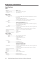
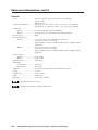
Appendix A • Specifications and Part Numbers ................................................... A-1
Specifications ....................................................................................................................... A-2
Part Numbers ....................................................................................................................... A-5
Included parts ................................................................................................................... A-5
Optional accessories ......................................................................................................... A-5
68-958-01 Rev. B
Printed in USA
10 04
All trademarks mentioned in this manual are the properties of their respective owners.
ii
TPS150 Switching and Transmission System • Table of Contents
TPS150 Switching and Transmission System
1
Chapter One
Introduction
About this Manual
About the Transmission System
TP Cable Advantages
Features
Introduction, cont’d
Introduction
About this Manual
This manual contains installation, configuration, and operating information for the
Extron TPS150 audio/video Twisted Pair (TP) switching and transmission system.
•
Chapter 1 identifies the transmitter’s and receiver’s features.
•
Chapter 2 details how to install the transmitter and receiver.
•
Chapter 3 describes how to operate the transmitter and receiver from their
front panels and use all of their features.
•
Chapter 4 provides information about programming and operating the
switcher under RS-232 control, such as from a PC or host controller. You can
control the switcher using Extron’s TPS150 serial command set or the ICS100
control program.
•
Appendix A lists the transmitter’s and receiver’s specifications and pertinent
part numbers.
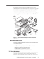
About the Transmission System
The TPS150 consists of two components: the TPT150 AV switcher/TP transmitter
(referred to in this manual as the “switching transmitter” or the “transmitter”) and
the TPR150 TP video receiver (referred to in this manual as the “receiver”)
(figure 1-1). The transmitter and receiver form a switching and long distance
transmission system. The TPS150 system sends high resolution RGB video (such as
VGA video), low resolution video, and RS-232 control signals to a projector, plasma
display, or other display over a single Category (CAT) 5 shielded twisted pair (STP)
or foil shielded twisted pair (FTP) cable. The system includes cable compensation
and skew control technology that allow you to use these standard network cables.
Extron recommends the use of STP or FTP cable only.
About the TPT150 switching transmitter
The TPT150 transmitter accepts and switches between the following four video
inputs:
•
Input 1 and input 2 — High resolution video (such as VGA) on 15-pin HD
connectors. Input 1 includes a buffered local monitor loop-through
connector.
•
Input 3 and input 4 — For each input, one only of the following three video
formats:
!
Component video (Y, R-Y, B-Y) on three female RCA connectors
!
S-video on one 4-pin mini DIN connector
!
Composite video on female RCA connector
Each input also accepts an unbalanced line level stereo audio signal on left and
right RCA connectors. The level of each audio input is individually adjustable to
ensure that there is no noticeable volume difference when switching among
sources.
The switching transmitter outputs the selected input audio as balanced or
unbalanced line level audio on a 5-pin 3.5 mm captive screw connector. The output
can also be muted.
The audio for the selected input is output locally. It is not sent to the receiver.
1-2
TPS150 Switching and Transmission System • Introduction
The TPT150 has an RS-232 port that accepts ICS100 program control from a
connected computer or serial command control from a computer or control system.
The transmitter can also store serial commands that are entered by the operator.
The transmitter sends the appropriate serial commands on the TP link to the
receiver whenever an input button or the projector power button is pressed.
An optional CTP150CM control panel can be connected to a contact closure port on
the TPT150. Using the CTP150CM, a remote operator can select inputs, power up
and down a projector connected to the receiver, and increase and decrease the
output volume.
Extron
TPR150
Control
System
Twisted Pair
Receiver
z
47; 0.2
63H
5A;
VAC
90-
RS
CO
OU
TP
MP
ON
EN
B
/ VG
MP
OS
ITE
2
PO
RT
RT:
PO
SUP17
L
ICA -71 00
HN 882 -18 om
0)
TEC (80 450 c.c
4)
nin .A.
(71 xtro U.S
w.E IN
ww DE
260
AY
E
V;
E:
MA
1.6
A;
DEL
TIM
250
FUS
!
UT
EO
B-Y
VID
CO
RG
-23
T
O
IDE
Y
S-V
R-Y
A
E
UM
VOL
AD
K
UT
P
SK
J
UT
INP
N
GR
RE
D
1
EW
LIN
BL
UT
INP
UE
UT
INP
3
AY
E
; 250
E:
V;
DEL
TIM
UT
INP
E
UM
VOL
TOR
JEC
PRO ER
POW
4
1.6A
FUS
T:
POR
SUP 7
CAL -711 0
HNI ) 882 -180 m
TEC (800 450 c.co
)
OTEL
(714 nein RT
REMTRO
.inli 2 PO
R
CON
GND PW www -23
J
PRO
VOL
T
OU
TPU
TP
Cable
L
INP
VID
INP
UT
2
AU
DIO
L
S-V
IDE
UT
S-V
IDE
UT
4
UP
T LIN
UP
IN4
DIO
+R
IN3
IN2
DIO
L
DIO
R-Y
Control
Panel
RS
DN
VOL
AU
AU
INP
VID
AU
3
Extron
CTP150CM
2
IN1
K
-
L
+
R-Y
R
EO
B-Y
O
Y
R
EO
B-Y
O
Y
R
AU
DIO
RG
B
/ VG
A
L
INP
Extron
TPT150
UT
1
NIT
L MO T
CA
LO OU TPU
RG
B
/ VG
OR
R
Sound
System
A
AV Switcher
PC
Input 1
VCR
Composite
Video
Input 3
DVD
Component
Video
Input 4
Laptop
Input 2
Figure 1-1 — Typical TPS150 Switching and Transmission System
application
About the TPR150 receiver
The TPR150 receiver accepts the TP link from the transmitter and outputs the
received video and RS-232 commands. The receiver outputs the following signals
on the following connectors:
•
High-resolution RGB video on one female 15-pin HD connector
•
Component video (Y, R-Y, B-Y) on three female RCA connectors
•
S-video on one female 4-pin mini DIN connector
•
Composite video on one female RCA connector
•
Serial (RS-232) commands on one male DB9 connector
TP Cable Advantages
Twisted pair cable is much smaller, lighter, more flexible, and less expensive than
coaxial cable. The TPT150 makes cable runs simpler and less cumbersome.
Termination of the cable with RJ-45 connectors is simple, quick, and economical.
TPS150 Switching and Transmission System • Introduction
1-3
Introduction, cont’d
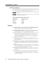
Transmission distance
The maximum distance is determined by the output frequency and resolution. The
following table specifies the recommended maximum transmission distances using
STP or FTP CAT 5 cable, terminated with CAT 5 rated connectors.
It is possible to exceed the recommended distance; however, image quality may
be reduced.
We recommend the use of pre-terminated and tested cables. Cables terminated
on site should be tested before use.
Recommended transmission ranges at 60 Hz
Video format
Maximum range
640 x 480
800 x 600
1024 x 768
1280 x 1024
1600 x 1200
500 feet
500 feet
500 feet
300 feet
250 feet
Features
Four input A/V switcher — Accepts, switches, and transmits RGBHV, component
video (Y, R-Y, B-Y), S-video, composite video, and RS-232 serial content.
Accepts and switches unbalanced line level stereo audio.
Buffered monitor output on input 1 — Provides for local monitor output on a
15-pin HD female VGA connector, enabling a signal to be easily monitored
locally without the need for a separate distribution amplifier.
Universal projector control — The TPS150 provides universal projector control via
serial commands entered by the installing technician. Commands are
automatically sent when the input selection or Projector Power buttons are
pressed. The included ICS100 control software makes storing projector or
display control codes easy
Skew compensation control — Individual red, green, and blue skew controls
adjust for the timing delays commonly encountered when CAT 5, CAT 5e, or
CAT 6 cable is used.
Sharpness control — Provides video equalization with individual low frequency
and high frequency adjustments. The low frequency control helps remove
image smearing. The high frequency control restores image sharpness and
detail.
Audio input level adjustment — Each individual input has a level adjustment via
the front panel and RS-232 control. Audio levels are saved for each input and
are automatically recalled when that input is selected.
Audio output volume adjustment and muting — The output has volume control
adjustment via the front panel, RS-232 control, or optional contact closure
panel control.
Control — Switcher control is available through the front panel, an RS-232 port
serial link, and an optional contact closure control panel. Serial control is
provided with the Extron ICS 100 control software and/or a control system
issuing serial commands.
1-4
TPS150 Switching and Transmission System • Introduction
Custom engraved front panels — The front panel controllers include attachment
posts to hold an optional custom-engraved name plate. Extron can create a
custom front plate to neatly and professionally label each input button.
Contact the Extron S3 Sales & Technical Support Hotline to order the custom
plate.
Optional CTP150CM control panel — Seven soft-touch buttons control the input
selection, volume up and down, and display power on and off. The
CTP150CM is available in a black or white finish and installs in CPM Series
modular connector panels that accept a quad-size Mini Architectural Adapter
Plate (MAAP).
TPS150 Switching and Transmission System • Introduction
1-5
Introduction, cont’d
1-6
TPS150 Switching and Transmission System • Introduction
TPS150 Switching and Transmission System
2
Chapter Two
Installation
Mounting the Transmitter and Receiver
Cabling and Rear Panel Views
TP Cable Termination
Installation, cont’d
Installation
Mounting the Transmitter and Receiver
The TPS150 comes with rubber feet for the transmitter and receiver, a set of
MTR102 rack ears for the transmitter, and a set mounting brackets for the receiver.
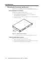
Rack mounting the transmitter
If desired, rack mount the transmitter as follows:
1.
Remove the rubber feet from the bottom of the transmitter.
2.
Attach the 992546-2 rack mounting ears to the transmitter with the six
provided #8 machine screws (figure 2-1).
3.
Insert the transmitter into the rack, aligning the holes in the mounting bracket
with those of the rack.
PO
MU
VO
C TO
O JE ER
PR W
PO
B LA
LU
W ER
TE
ME
R
NK
4
3
2
1
IN
# 8 Screw (6 Plcs)
Each Side
TP
T 15
0 A/
V
Sw
itc
he
Tw
r/
is te
d Pa
ir
Tr
an
sm
itt
PU
T SE
LE
CT
er
Figure 2-1 — Mounting the transmitter
4.
Secure the transmitter to the rack using the supplied machine screws.
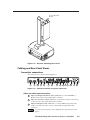
Projector mounting the receiver
If desired, projector mount the receiver as follows:
2-2
1.
Remove the rubber feet from the bottom of the receiver.
2.
Attach the supplied 992547-2 projector pole mounting brackets to the receiver
with the four provided #8 machine screws (figure 2-2).
TPS150 Switching and Transmission System • Installation
Projector Mounting
Bracket
TPR150
Twisted Pair Video Receiver
SELECT
CABLE EQUALIZATION
- ADJUST +
P OW E R
L OW F R E Q .
HIGH FREQ.
Figure 2-2 — Projector mounting the receiver
Cabling and Rear Panel Views
Transmitter connections
All connectors are on the rear panel (figure 2-3).
INPUT 1
INPUT 2
AUDIO
RGB / VGA
INPUT 3
AUDIO
L
LOCAL MONITOR
OUTPUT
INPUT 4
R-Y
VIDEO
AUDIO
L
RGB / VGA
AUDIO
PROJ PWR
AUDIO
UTP LINK
VOL DN
+
R
R
Y
B-Y
R
R
R
Y
100–240 V .3A
GND
L
S-VIDEO
S-VIDEO
CONTACT
CLOSURE
OUTPUT
R-Y
VIDEO
L
VOL UP
IN4
IN3
L
+
B-Y
IN2
IN1
50–60 Hz
1
2
4
1
4
3
4
3
4
5
6
7
8
9
10
Figure 2-3 — TPT150 transmitter rear panel connectors
Video and audio input connections
1
Input 1 and Input 2 RGB/VGA video connectors — Connect RGBHV or
RGBS sources to these 15-pin HD female connectors.
2
Input 1 local monitor output connector — If desired, connect a local monitor
or other device to this 15-pin HD female connector.
3
Input 3 and Input 4 video connectors — Connect either component video,
S-video, or composite video sources to these BNC and 4-pin mini DIN
connectors.
For proper system operation, connect only one video format to input 3 and
input 4.
TPS150 Switching and Transmission System • Installation
2-3
Installation, cont’d
Connect the various video formats as shown in figure 2-4.
INPUT 3
Component
video
INPUT 3
R-Y
VIDEO
VIDEO
S-VIDEO
R-Y
S-video
S-VIDEO
Y
B-Y
Composite
video
VIDEO
Y
B-Y
INPUT 3
R-Y
S-VIDEO
Y
B-Y
Figure 2-4 — Input 3 and input 4 video format connections
4
Input audio connectors — Connect unbalanced stereo or mono audio sources
to these pairs (left and right) of RCA connectors for audio input.
TP and audio output connections
5
TP connector — Connect one end of an STP or FTP cable to this RJ-45 female
connector on the transmitter.
Connect the free end of the same TP cable from the transmitter to the RJ-45
female connector on the receiver.
See TP cable termination, on page 2-6, to properly wire the RJ-45 connector.
Extron recommends the use of STP or FTP cable only.
6
Audio connector — Connect an audio device, such as powered speakers, to
this 3.8 mm, 5-pole captive screw connector for balanced or unbalanced audio
output.
Figure 2-5 shows how to wire the captive screw audio connector. The
connector is included with the transmitter, but you must obtain the cable.
Insert the wires into the appropriate openings in the captive screw connector.
Tighten the screws on top to fasten the wires.
CAUTION
Wiring the audio incorrectly can damage the audio output circuits.
Connect the sleeve(s) to ground (GND). Connecting the sleeve(s) to a
negative (-) terminal will damage audio output circuits.
Unbalanced Output
Tip
Ring
Sleeve (s)
Tip
Ring
L
Tip
See caution
Sleeve(s)
Tip
See caution
Balanced Output
Figure 2-5 — Wiring the audio output connector
The audio output always follows the video switch.
2-4
TPS150 Switching and Transmission System • Installation
Remote control connections
7
Contact Closure — If desired, connect an optional CTP150CM control panel
module or other contact closure device to this 8-pin 3.5 mm
CONTACT
captive screw connector. Refer to the CTP150CM manual.
CLOSURE
To make your own contact closure device, wire the connector
as shown at right. To issue a switching, volume, or projector
power command, momentarily short the appropriate pin to
ground.
8
RS-232 port — Connect a host device, such as a computer or
touch panel control, to the TPT150 transmitter via this 9-pin
D connector and a null modem serial port cable for serial
RS-232 control (figure 2-6).
Connected
TPS150
RS-232
pin
device pin
—
1
RX
2
TX
3
—
4
Gnd
5
—
6
—
7
—
8
—
9
Function
Not used
Receive data
Transmit data
Not used
Signal ground
Not used
Not used
Not used
Not used
5
GND
PROJ PWR
VOL DN
VOL UP
IN4
IN3
IN2
IN1
1
9
6
Female
Figure 2-6 — Remote port pin assignments for the TPT150 and TPR150
See chapter 4, Serial Communications, for definitions of the ASCII commands
and instructions to install and use the control software.
Power connection
9
AC power switch — Toggle the AC power switch to the on ( ) position to turn
on the transmitter.
10
AC power connector — Plug a standard IEC power cord into this connector
to connect the transmitter to a 100 to 240VAC, 50 Hz to 60 Hz power source.
Receiver connections
All receiver connectors are on the rear panel (figure 2-7).
9 0 - 2 6 0 VAC ; 0 . 2 5 A ; 4 7 - 6 3 H z
VIDEO OUTPUT
COMPOSITE
SKEW
COMPONENT
RS-232 PORT
S-VIDEO
ADJ
R-Y
Y
U S E O N LY W I T H 2 5 0 V F U S E
RGB / VGA
UTP LINK
B-Y
RED BLUE GRN
F U S E : 1 . 6 A ; 2 5 0 V; T I M E D E L AY
11
12
13 14
15
16
17
Figure 2-7 — TPR150 receiver rear panel connectors
TP input connection
11
TP connector — Connect the free end of the STP or FTP cable from the
transmitter to this RJ-45 female connector on the receiver.
See TP cable termination, on page 2-6, to properly wire the RJ-45 connector.
TPS150 Switching and Transmission System • Installation
2-5
Installation, cont’d
Video output connections
12
RGB/VGA video connector — Connect a VGA cable between this 15-pin HD
female connector and the VGA or RGB input on the display.
13
Composite video connector — Connect a video cable between this BNC
female connector and the composite video input on the display.
14
S-video connector — Connect an S-video cable between this 4-pin mini DIN
female connector and the S-video input on the display.
15
Component video connector — Connect a cable between these BNC female
connectors and the component video input on the display.
Serial connection
16
RS-232 connector — Connect a serial cable (figure 2-6) between this 9-pin D
connector and the RS-232 connector on the display for control of the display.
Power connection
17
AC power connector — Plug a standard IEC power cord into this connector
to connect the receiver to a 100 to 240VAC, 50 Hz to 60 Hz power source.
The receiver is protected by a 1.6 A, 250 V, time delay fuse. If necessary,
replace with a time delay fuse with the same amperage and voltage rating.
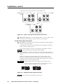
TP Cable Termination
RJ-45 termination must comply with the TIA/EIA T 568A or TIA/EIA T 568B
wiring standards for all connections.
Extron recommends the use of STP or FTP cable only.
Figure 2-8 details the recommended termination of CAT 5 TP cable with RJ-45
connectors in accordance with the TIA/EIA T 568A or TIA/EIA T 568B wiring
standards. You can use either standard, but ensure that you use the same standard
on both ends of the cable.
Side
Clip Down
Pins 1 2 3 4 5 6 7 8
RJ-45
connector
Pin
7&8
3&6 4&5
RGB video
signals
White-green
White-orange
Blue +/V. sync +
B-Y +
Green
Orange
Blue –/V. sync –
B-Y –
3
White-orange White-green
RS-232 +
RS-232 +
4
Blue
Blue
Green +/H. sync + Y +
5
White-blue
White-blue
Green –/H. sync – Y –
6
Orange
Green
RS-232 –
RS-232 –
7
White-brown
White-brown
Red –
R-Y –
8
Brown
Brown
Red +
R-Y +
568 A
Wire color
568 B
Wire color
1
White-green
White-orange
2
Green
Orange
S-video signals
Composite video
signals
3
White-orange White-green
RS-232 +
RS-232 +
4
Blue
Blue
Y+
Video +
5
White-blue
White-blue
Y–
Video –
6
Orange
Green
RS-232 –
RS-232 –
7
White-brown
White-brown
C–
8
Brown
Brown
C+
Figure 2-8 — TP cable termination
2-6
Component video
signals
1
Pin
1&2
568 B
Wire color
2
12345678
Twisted
Pairs
568 A
Wire color
TPS150 Switching and Transmission System • Installation
TPS150 Switching and Transmission System
3
Chapter Three
Operation
Controls and Indicators
Operations
Optimizing the Video
Troubleshooting
Operation, cont’d
Operation
Controls and Indicators
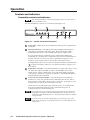
Transmitter controls and indicators
The TPT150 transmitter will not operate properly unless it is connected to a
powered TPR150 receiver.
All of the transmitter’s controls are on the front panel (figure 3-1).
7
7
1
TPT150 A/V Switcher / Twisted Pair Transmitter
2
3
4
5
BLANK
PROJECTOR
POWER
3
4
VOLUME
MUTE
POWER
6
1
INPUT SELECT
2
Figure 3-1 — TPT150 transmitter front panel
1
Power LED — When lit, the Power LED indicates that power is applied to the
transmitter.
2
Input Select buttons — The Input 1 Select through Input 4 Select buttons
select the associated video and audio input. The selected video input is
transmitted to the receiver. The selected audio input is output locally.
If a user-specified serial command is set for an Input Select button, the
transmitter also sends that serial command to the receiver when the button is
pressed. The receiver, in turn, issues the command to the projector. See
chapter 4, Serial Communications, to specify the command to be sent.
The Input Select buttons are also used in conjunction with the Volume buttons
( 5 ) to adjust each input’s audio level. See Volume adjustment on page 3-5 for
more details.
3
Blank button and LED — Press the Blank button to toggle video mute on and
off. When the output is blanked, no video is transmitted to the receiver,
which, in turn, outputs a blank image. The video mute function mutes the
video signals only; the sync signal(s) are still active. The Blank LED lights to
indicate that the video is blanked.
4
Projector Power button and LED — Press the Projector Power button to
transmit one of two user-specified serial commands to the receiver, which
then issues the command to a device such as a projector. See chapter 4, Serial
Communications, to specify the command(s) to be sent.
The Projector Power LED lights green when the power on command is the
most recent command transmission and is unlit when the power off
command is the most recent transmission.
If a projector power on (warm-up) delay or projector power off (cool-down) is
programmed (see chapter 4, Serial Communications), the Projector Power
LED blinks while that delay times out. All front panel operations are disabled
during the delay.
Some projectors use the same command for power on and power off. If the
same code is specified for on and off, the Projector Power LED blinks for each
button push.
3-2
TPS150 Switching and Transmission System • Operation
5
Volume up and down buttons — The Volume up ( ) and Volume down ( )
buttons are used to increase and decrease the output volume and the selected
input’s audio level. See Volume adjustment on page 3-5 for more details.
The Volume buttons are also used to reset the transmitter. See Full system reset
on page 3-5.
6
Mute button and LED — Press the Mute button to toggle audio mute on and
off. When the output is muted, the transmitter outputs no audio on its local
Audio connector. The Mute LED lights to indicate that the audio is muted.
7
Faceplate posts — These posts can hold an optional custom-engraved name
plate. Extron can create a custom front plate to neatly and professionally label
each input button. Contact the Extron S3 Sales & Technical Support Hotline to
order the custom plate.
Receiver controls and indicators
The receiver has controls on the front panel and the rear panel (figure 3-2).
C A B L E E QUA L I Z AT I O N
- ADJUST +
SELECT
LOW FREQ.
HIGH FREQ.
POWER
TPR150
Tw i s t e d Pa i r V i d e o R e c e i v e r
10
11
9 0 - 2 6 0 VAC ; 0 . 2 5 A ; 4 7 - 6 3 H z
VIDEO OUTPUT
COMPOSITE
SKEW
COMPONENT
S-VIDEO
R S - 2 3 2 P O RT
ADJ
R-Y
Y
U S E O N LY W I T H 2 5 0 V F U S E
R G B / VG A
UTP LINK
8
9
B-Y
RED BLUE GRN
F U S E : 1 . 6 A ; 2 5 0 V; T I M E D E L AY
Figure 3-2 — TPR150 receiver front panel
8
Power LED — When lit, the Power LED indicates that power is applied to the
receiver.
9
Cable Equalization Select button and LEDs — Press the Select button to
toggle between high frequency and low frequency to equalize. The High
Frequency LED and Low Frequency LED indicate the frequency range that is
selected for equalization. Equalize the cable with the Adjust button ( 10 ). See
Optimizing the Video on page 3-6 for more details.
10
Cable Equalization Adjust button — Press the + side of the button to
increase the amount of equalization applied to the selected frequency range
(high or low) of the output signal. Press the – side of the button to decrease
the amount of equalization. Select the frequency range with the Select button
( 9 ). See Optimizing the Video on page 3-6 for more details.
11
Skew Adjustment controls — Use an Extron Tweeker or other small
screwdriver to correct for the delay inherent in network (CAT 5) cable. See
Optimizing the Video on page 3-6 for more details.
TPS150 Switching and Transmission System • Operation
3-3
Operation, cont’d
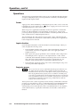
Operations
The following paragraphs detail the power-up process and then describe selecting
an input, issuing the projector power up and down commands, and adjusting the
input level and output volume.
Power
Apply power to the transmitter by connecting the power cord to an AC source and
toggling the AC power switch to the on ( ) position. Apply power to the receiver by
connecting the power cord to an AC source.
When AC power is applied, the transmitter and receiver perform a self-test that
flashes all of the transmitter’s front panel LEDs on and off once. An error-free
power up self-test sequence leaves the transmitter’s selected input LED, the Power
LEDs, and the receiver’s High Frequency LED on.
The selected input, the audio input level and output volume, and the blank and
mute on/off status are saved in non-volatile memory. When power is applied, the
latest configuration is retrieved.
Input selection
Press the Input Select button on the transmitter for the desired input. When you
select an input, the following occurs:
•
The transmitter sends the video portion of the selected input to the receiver
on the TP link. The receiver outputs the video on its appropriate Video
Output connectors.
•
If the operator has pre-programmed a serial command or data string for the
selected input (such as a projector’s own input selection or video format
command), the transmitter sends that serial string to the receiver on the TP
link. The receiver then outputs the serial string on its RS-232 port. See
chapter 4, Serial Communications, to specify the command to be sent.
•
The transmitter outputs the audio portion of the selected input locally, on its
own rear panel Audio Output port.
Projector power
The receiver does not receive a confirmation from the projector that it is on or
off. Rather, after the TPT150’s power is applied, the first serial string the
transmitter sends to the receiver (which passes it to the projector) is the string
that was programmed as the projector power on command. From that point,
every time you push the button, the transmitter alternates between sending the
power off command and the power on command. If the projector is powered on
or off locally, the transmitter sends the wrong command the next time the
Projector Power button is pressed.
The Projector Power control is typically used to remotely command the connected
projector to power itself up or down. Command strings to be transmitted must be
programmed in advance. The projector power timeout function (if enabled)
automatically powers off the projector after a user-defined interval. See chapter 4,
Serial Communications, to specify the commands to be sent and to set the timout
function.
3-4
TPS150 Switching and Transmission System • Operation
Press the Projector Power button on the transmitter to issue the projector on or off
command. When you push the button, the following occurs:
•
If no command has been transmitted since transmitter power was applied, or
if the power off command was the last command transmitted:
!
The transmitter sends the power on string to the receiver on the TP link.
!
The transmitter lights its Projector Power LED.
!
The transmitter starts its power off timout function (if enabled).
!
The receiver outputs the received serial string on its RS-232 port.
Some projectors use the same command for power on and power off. If the
same code is specified for on and off, the Projector Power LED blinks for each
button push.
•
If the power on command was the last command transmitted:
!
The transmitter sends the power off string to the receiver on the TP link.
!
The transmitter turns off its Projector Power LED.
!
The receiver outputs the received serial string on its RS-232 port.
The same sequence of events occurs when the projector power timeout function
(if enabled) expires.
Volume adjustment
Output volume —
Press and release the Volume up ( ) or Volume down ( ) button to increase or
decrease the output volume by 1dB per button push or press and hold the button to
ramp the output volume up or down.
Input audio level —
1.
Press and hold the desired Input Select button.
2.
While you continue to hold the Input Select button, press and release the
Volume up ( ) or Volume down ( ) button to increase or decrease the
selected input’s volume or press and hold the button to ramp the selected
input’s volume up or down.
3.
Release the Input Select button.
Full system reset
To restore the I/O configurations, projector codes, volume levels, and serial setup
to the default setting, press and hold the transmitter’s Volume up ( ) and Volume
down ( ) buttons while you apply power to the transmitter. Continue to hold the
Volume buttons until the transmitter LEDs stop changing and then release the
Volume buttons.
Receiver reset
To reset a TPR150 receiver to its default settings, disconnect TPT150 transmitter
power for 10 seconds or more.
TPS150 Switching and Transmission System • Operation
3-5
Operation, cont’d
Optimizing the Video
The TPR150 receiver features cable equalization controls for high and low
frequency adjustments and RGB skew control to compensate for misconvergence of
colors that can result from long CAT 5 cable runs. The following steps detail how
to use these features to optimize the output image.
These adjustments should be made with the highest resolution input selected
on the TPT150 transmitter.
1.
Carefully set the rear panel RGB skew controls to minimum
(fully counterclockwise).
2.
Power up the transmitter, receiver, and display.
3.
Select the highest resolution.
4.
As needed, use the front panel low
frequency control to eliminate any
visible image smear.
5.
6.
SKEW
ADJ
RED BLUE GRN
CABLE EQUALIZATION
- ADJUST +
SELECT
LOW FREQ.
HIGH FREQ.
a.
If necessary, press and release
the Cable Equalization Select
button to light the Low Frequency LED.
b.
Press the + side of the button to increase the amount of equalization
applied to the output signal’s low frequency range. Press the – side of
the button to decrease the amount of equalization.
As needed, use the front panel high frequency control to maximize the detail
and sharpness.
a.
If necessary, press and release the Cable Equalization Select button to
light the High Frequency LED.
b.
Press the + side of the button to increase the amount of equalization
applied to the output signal’s high frequency range. Press the – side of
the button to decrease the amount of equalization.
If the red, green, and blue video are not properly aligned, use a Tweeker or
small screwdriver to gently adjust the red, green, and/or blue Skew
Adjustment controls to correct for the delay inherent in network (CAT 5)
cable.
The Skew Adjustment controls are sensitive. Make each adjustment carefully.
7.
3-6
Repeat steps 4 through 6 to fine tune the adjustments.
TPS150 Switching and Transmission System • Operation
Troubleshooting
This section gives recommendations on what to do if you have problems operating
the transmitter/receiver system, and it provides examples and descriptions for
some image problems you may encounter.
The following tips may help you in troubleshooting.
•
Some symptoms may resemble others, so you may want to look through all
of the examples before attempting to solve the problem.
•
Be prepared to backtrack in case the action taken does not solve the problem.
•
It may help to keep notes and sketches in case the troubleshooting process
gets lengthy. This will also give you something to discuss if you call for
technical support.
•
Try simplifying the system by eliminating components outside the system
that may have introduced the problem or made it more complicated.
•
For sync-related problems: Portable digital projectors are designed to operate
close to the immediate video source (the receiver). Sync problems may result
from using long cables or from improper termination. A sync adapter, such
as Extron’s ASTA (active sync termination adapter), may help solve these
problems.
•
For LCD and DLP projectors and plasma displays: In addition to the syncrelated information above, check the user’s manual that came with the
projector for troubleshooting tips, as well as for settings and adjustments.
Each manufacturer may have its own terms, so look for terms like “auto
setup,” “auto sync,” “pixel phase,” and “tracking.”
General checks
1.
Ensure that all devices are plugged in and powered on. The transmitter and
receiver both have Power LEDs to indicate that power is applied.
2.
Ensure that the input selected is active.
3.
Ensure that the proper signal format is supplied.
4.
Check the cabling and make corrections as necessary.
5.
Reset the switcher. See Full system reset on page 3-5.
6.
Call the Extron S3 Sales & Technical Support Hotline if necessary.
TPS150 Switching and Transmission System • Operation
3-7
Operation, cont’d
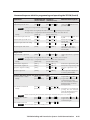
Specific problems
The table below shows some common operating problems and their solutions.
Problem
Possible cause
Solution
No image appears.
System not receiving
power
Ensure that the video source, the
transmitter and receiver, and the
display are plugged into a live AC
power source and the transmitter
is turned on.
Check that the input device is
sending a video signal to the
transmitter.
Select a different input. If a screen
display does not appear, check the
output connection.
On the projector, manually check
that the input and format are
correct. If not, check that the
proper signal string for the input
selection is programmed into the
transmitter.
Press the transmitter’s Blank
button to disable video mute.
Follow the steps in Optimizing
the Video on page 3-6.
No video input
No video output
The projector has the
wrong input/signal
format selected.
Video may be muted.
Distorted image
appears.
3-8
Improperly adjusted
receiver
TPS150 Switching and Transmission System • Operation
TPS150 Switching and Transmission System
4
Chapter Four
Serial Communications
ICS100 Windows Control Program
Serial Commands
Serial Communications,
cont’d
Serial
Communications
The transmitter must be programmed with commands to be sent upon input
selection and with projector power on/off commands before those commands will
be sent.
The transmitter can also be configured with several serial port variables to match
the controlling device and the device to be controlled.
You can program and operate the transmitter either by using the ICS100 Windowsbased control program or by sending individual ASCII commands. Both
programming methods require that a null modem serial port cable be connected
between a computer and the transmitter’s RS-232 port.
ICS100 Windows-Based Control Program
The ICS100 Control Program, a graphical control software for Windows, provides a
way to program the transmitter.
System requirements
•
Operating system —
Windows 95 / 98 / ME / NT / 2000 / XP / XP Pro
If you are using Windows NT, Service Pack 6 must be installed.
•
Hardware — Pentium 150 or faster CPU
•
Memory — Minimum: 128 MB
Recommended: 256 MB
•
Screen resolution — Minimum: 800 x 600
Recommended: 1024 x 768
•
Disk space — 5 MB
Installing the software
The control program is contained on a CD-ROM, and must be installed on the hard
drive.
4-2
1.
Click Start > Run.
2.
Click the Browse button. An open file window appears.
3.
Navigate to the drive or folder that contains the software.
4.
Double-click the setup icon.
5.
Click OK in the Run window.
6.
Click OK in the InlineControl Setup window.
7.
Follow the instructions in the setup program to complete the installation.
TPS150 Switching and Transmission System • Serial Communications
Establishing communications with the program
The TPT150 transmitter will not operate properly unless it is connected to a
powered TPR150 receiver.
Start the control program and establish communications with the TPT150 as
follows:
1.
Click Start > Programs > Extron > ICS100. The control program window
appears.
The TPS150 does not respond until it has been contacted with the valid
address.
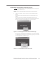
If you have previously connected to the transmitter and you have not
addressed any other device since then, after a moment, the program reports
that it has connected to a TPT150 (figure 4-1). Proceed to step 10.
Figure 4-1 — ICS100 program window and connected message
If you have not connected to the transmitter before or if you have connected
to a different device since then, after a moment, the program reports a failure
to connect (figure 4-2). Continue to step 2.
Figure 4-2 — ICS100 program window and warning
TPS150 Switching and Transmission System • Serial Communications
4-3
Serial Communications, cont’d
The transmitter’s serial port is factory-configured to 9600 baud, no parity, no
flow control, half-duplex mode. If desired, the computer’s serial port settings
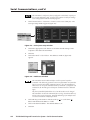
can be changed from within the ICS100 program.
2.
Click Communications > Comm Port > Comm 1 (or the correct Comm port). The
serial port setup window appears (figure 4-3).
Figure 4-3 — Serial port setup window
3.
Click in the appropriate radio buttons to select the desired settings for the
computer connected to the transmitter.
4.
Click OK.
5.
Click Inline Model > Select Address. The addresses window (figure 4-4)
appears.
Figure 4-4 — Addresses window
The transmitter must be addressed before it will accept and respond to
commands. The addressing operation routes setup information to a particular
unit on a network and enables command responses. Once the transmitter is
addressed, it can accept an unlimited number of commands. If a different unit
is addressed, the TPS150 ignores subsequent commands until it is addressed
again.
The factory-installed default address is 97, but this number can be changed.
The transmitter can also take commands after receiving a broadcast address of
00, but it does not send responses. Broadcast addressing is for multiple units
on a network serial line in half-duplex mode.
4-4
6.
Click and drag on the slider or click the scroll up ( ) or scroll down ( )
button until the desired address is visible.
7.
Click on the desired address. The default address is 97.
8.
Click OK.
TPS150 Switching and Transmission System • Serial Communications
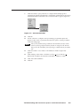
9.
Click Inline Model > Query Hardware to configure the ICS100 program to
communicate with the TPT150 and to confirm that communications have been
established with the transmitter. The connected window appears (figure 4-5).
Figure 4-5 — Connected window
10.
Click OK.
11.
Use the software to configure serial port settings, program the input and
projector codes, and/or operate the transmission system. See the procedures
on the following pages.
After you are finished sending commands to the transmitter, always end the
session by selecting a different address from the one assigned to the TPT150.
This prevents the transmitter from responding to commands meant for another
unit.
12.
Click Inline Model > Select Address. The Addresses window (figure 4-4)
appears.
13.
Click and drag on the slider or click the scroll up ( ) or scroll down ( )
button until an address other than the transmitter’s address is visible.
14.
Click on the desired address.
15.
Click OK.
TPS150 Switching and Transmission System • Serial Communications
4-5
Serial Communications, cont’d
Using the software to configure the serial port settings
If necessary, use the ICS 100 software to change the serial port settings of either the
transmitter or receiver.
The transmitter’s serial port is factory-configured to 9600 baud, no parity, no
flow control, half-duplex mode. If desired, serial port settings can be changed
from within the ICS100 program.
1.
Click Communications > Comm Port > Comm 1 (or the correct Comm port). The
serial port setup window appears (figure 4-6).
Figure 4-6 — Serial port setup window
2.
Click in the appropriate radio buttons to select the desired settings for the
transmitter and the receiver.
The receiver’s RS-232 port should be connected to the display device’s
communications port. Refer to the display device’s user manual for the
appropriate serial port protocol and settings.
The transmitter and receiver are buffered and can operate with different serial
port protocols.
3.
Click OK.
If you change the serial protocols, communications between the computer and
the transmitter are lost until the computer is updated to match the new
transmitter settings).
4.
4-6
If no further operations are to be performed, halt communication with the
switcher by selecting a different address. See Establishing communications with
the program, step 12.
TPS150 Switching and Transmission System • Serial Communications
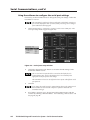
Using the software to program the input and projector codes
Use the control program to program the transmitter’s input selection and projector
power on/off buttons as follows:
1.
Click Controls > Projector Codes > Input Codes. The Program Projector Codes
window appears (figure 4-7).
Figure 4-7 — Program Projector Codes window
2.
For each input or projector code to be programmed:
a.
Click and drag the slider to select the desired input or projector code or
enter one of the following into the field above the slider (figure 4-8):
•
1 through 4 — Input 1 through 4 code
•
5 — Power off code
•
6 — Projector on code
Figure 4-8 — Input or projector code selection
b.
Click in the ASCII or Hex radio button to select the appropriate format.
Selecting the Hex radio button causes the transmitter to convert the primary
code that you will enter in step 2c to a hex value before saving it. Then, when
you press the button, the transmitter sends the hex value.
TPS150 Switching and Transmission System • Serial Communications
4-7
Serial Communications, cont’d
c.
Enter the desired code in the code window (figure 4-9).
Spaces are ok when you are entering ASCII codes.
Figure 4-9 — Code entry (ASCII code)
Codes that are intended to be hex codes must be in pairs (such as 03 or DE).
Use a leading 0 if necessary. Letters must be uppercase. Spaces between bytes
are acceptable in ASCII codes (figure 4-9), but are not allowed in hex codes
(figure 4-10).
01234
hex
Figure 4-10 — Code entry (hex code)
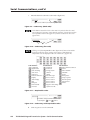
Clicking one of the Unprintable Codes (figure 4-11) buttons inserts that
function into the line feed or carriage return string of data characters.
Unprintable codes are displayed in the code window as | (figure 4-12).
Code Definition
Code Definition
Code Definition
Left bracket
Vertical tab
End of transmission block
Cancel
Right bracket
Form feed
End of medium
Start of heading
Carriage return
Substitute
Start of text
Shift out
Shift in
End of text
Escape
End of transmission
Data link escape
File separator
Enquiry
Group separator
Device control 1
Acknowledge
Record separator
Device control 2
Bell
Unit separator
Device control 3
Backspace
Delete
Device control 4
Horizontal tab
Negative acknowledge
Line feed
Synchronous idle
Figure 4-11 — Unprintable codes
|| indicates carriage return/line feed entered
by pushing the
and
buttons.
Figure 4-12 — Code entry with unprintable codes
d.
4-8
Click Program to save the command.
TPS150 Switching and Transmission System • Serial Communications
3.
Repeat step 2 for each button or code to be programmed.
4.
Click
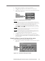
5.
Click Controls > Projector Codes > Projector Delay. The program projector delay
window appears (figure 4-13).
in the upper right corner of the window to close the window.
Figure 4-13 — Program projector delay window
When you open the window, the ICS 100 automatically resets the projector
delay in the transmitter to 0 seconds and displays 000 in the variable window.
6.
For the power on (warm-up) delay (0 to 60 seconds) and power off
(cool-down) delay (0 to 256 seconds), click and drag the slider or click the
scroll left ( ) or scroll right ( ) button until the desired interval (in seconds)
appears in the variable window.
The ICS100 program automatically sends the revised projector delay to the
transmitter as soon as you move the slider.
If you click the Projector On or Projector Off button, the Projector Power
LED on the transmitter’s front panel blinks while the delay times out. All
front panel operations are disabled during the delay.
7.
Click
8.
If no further operations are to be performed, halt communication with the
switcher by selecting a different address. See Establishing communications with
the program, step 12.
in the upper right corner of the window to close the window.
Using the software to operate the transmission system
Use the control program to operate the transmitter as follows:
1.
Click Controls > Control Panel. The transmitter control panel window appears
(figure 4-14).
Figure 4-14 — Transmitter control panel window
TPS150 Switching and Transmission System • Serial Communications
4-9
Serial Communications, cont’d
With the exception of input audio level, the controls on the control panel
window operate the same as the physical front panel of the transmitter. See
chapter 3, Operation.
2.
If you click the Projector On or Projector Off button, the Projector Power
LED on the transmitter’s front panel blinks while the delay times out. All
front panel operations are disabled during the delay.
The
button mutes and unmutes the audio output.
For input volume control, click Controls > Input Volume. The Set Input Volume
window appears (figure 4-15).
3.
Figure 4-15 — Transmitter input volume window
a.
For each input, select that input on the front panel.
b.
Click and drag on the slider or click the scroll up ( ) or scroll down ( )
button to adjust the input level from 0dB (unity) through –15dB as
required for best performance.
Clicking the Reset Volume button resets each input’s audio level to 0db
(unity).
4.
Click
5.
If no further operations are to be performed, halt communication with the
switcher by selecting a different address. See Establishing communications with
the program, step 12.
in the upper right corner of the window to close the window.
Using the help system
For information about program features, you can access the help program in the
following ways:
4-10
•
From the ICS100 startup window, select Help from the Help menu.
•
From the Button Codes window, press the F1 key.
TPS150 Switching and Transmission System • Serial Communications
Serial Commands
Communication protocols
The transmitter’s and receiver’s serial ports (figure 4-16) are factory-configured to
9600 baud, no parity, no flow control, half-duplex mode. If you change the
transmitter’s serial protocols, communications between the computer and the
transmitter are lost until the computer is updated to match the new transmitter
settings.
Connected
TPS150
RS-232
pin
device pin
—
1
RX
2
TX
3
—
4
Gnd
5
—
6
—
7
—
8
—
9
Function
Not used
Receive data
Transmit data
Not used
Signal ground
Not used
Not used
Not used
Not used
5
1
9
6
Female
Figure 4-16 — Remote port pin assignments for the TPT150 and TPR150
The communications protocols of the receiver should match the protocols of the
device to be controlled.
Command and response structure
Valid commands consist of a leading delimiter, one or more characters in a
command code, and an ending delimiter. The transmitter ’s response to an RS-232
command also consists of a leading delimiter, a command code, and an ending
delimiter.
The transmitter’s leading delimiter code is always a left bracket ( [ ). The ending
delimiter code is always a right bracket ( ] ).
Example: [CPp@] — where “[“ is the leading delimiter, “CPp@” is the command
(reset the transmitter’s serial port to default values), and “]” is the ending delimiter.
Addressing the transmitter
The transmitter must be addressed before it will accept and respond to commands.
The address packet ([CC##], where ## is the 2-digit address ) routes setup
information to a particular unit on a network and enables command responses.
Once the transmitter is addressed, it can accept an unlimited number of commands.
If a different unit is addressed, the TPT150 ignores subsequent commands until it is
addressed again.
The factory-installed default address is 97, but this number can be changed. The
transmitter can also take commands after receiving a broadcast address of 00, but it
does not send responses. Broadcast is for multiple units in a network configuration
in half duplex mode.
By definition, the display device connected to the receiver’s RS-232 port is assigned
an address that is one larger than the transmitter’s (for example, 98 to the
transmitter’s default 97). If you address the display, the transmitter passes the
commands received directly through to the receiver’s RS-232 port, allowing you to
control the display. The transmitter also passes responses on the receiver’s RS-232
port back to its own serial port.
TPS150 Switching and Transmission System • Serial Communications
4-11
Serial Communications, cont’d
When the system is in Pass-Through mode [CC98], commands and responses are
sent between the transmitter and receiver. If the system is not in Pass-Through
mode, all of the receiver responses to the transmitter’s button commands are
buffered until you return the system to pass-through mode, at which time the
buffered responses are sent back to the controlling device. In this way, the
controller can track the activity that has occurred.
After you are finished programming the transmitter, always terminate the session
by sending an address packet to another unit with a different address. This
prevents the transmitter from responding to commands meant for another unit.
Transmitter responses
When a command is valid, the transmitter performs the command and sends the
following response:
[R0•{address}•{echo of the command sent}•]
When a command is invalid, either because the command is not recognized or it
contains invalid parameters, the transmitter sends the following response:
[R1•{address}•{echo of the command sent}•]
Using the command/response table
The command/response table begins on page 4-14. The command set is case
sensitive and commands must be entered as shown. The table below shows the
hexadecimal equivalent of each ASCII command.
ASCII to HEX Conversion Table
Space
Symbols, defined below, are used throughout the command/response table to
represent variables in the command/response fields. Command and response
examples are shown throughout the table.
Symbols
=
•
X1
Carriage return/line feed
= Space
=
Address number
00 – 97
00 addresses all units, but individual units do not respond.
97 is the factory-installed default for the transmitter.
Transmitter address + 1 is defined as the device connected to the receiver’s RS-232 port.
The very first command that you send to the transmitter must be the connect, [CC X1 ], command, where
X1 is the transmitter’s address. The transmitter will not accept other commands or respond until it has
been addressed.
The very last command that you send to the transmitter should be the connect, [CC X1 ], command, where
X1 is a different address. This prevents the transmitter from accepting and responding to commands
meant for other devices.
4-12
TPS150 Switching and Transmission System • Serial Communications
X2
=
Input number
01 – 04
X3
=
On/off status
0 = off, 1 = on
X4
=
Input volume
–15 (dB) of attenuation (minimum volume) through 00 (dB) (maximum volume)
X5
=
Output level
–31 (dB) of attenuation (maximum attenuation) through 20 (dB) (maximum gain)
X6
=
Button or code
01 = input 1 code
02 = input 2 code
03 = input 3 code
X7
=
ASCII button code Up to 63 alphanumeric characters.
If you need to use the bracket delimiters in a stored ASCII command, you need to use
the insert brackets feature. With this feature, one character replaces the left bracket
( [ ) and another character replaces the right bracket ( ] ). The default values are a
single quote mark ( ‘ ) in place of the left bracket and a double quote ( “ ) in place of
the right bracket. The TPT150 replaces the characters with the bracket delimiters in
the stored ASCII or hex command string.
X8
=
Hex button code
04 = input 4
05 = projector power off code
06 = projector power on code
Similar to the ASCII button code, X7 , with the addition of an ASCII-to-hex conversion
before the value is stored. For example, if you send the ASCII value 0F, the TPT150
converts it to the hex value 0F. When you press the button, the TPT150 sends 0F hex.
Entries must be in pairs; use a leading 0 if necessary. Letters must be uppercase.
Spaces between bytes are not allowed.
The insert brackets feature is not available for hex codes.
X9
=
Projector power timeout interval
000 or 001 - 255 (minutes). 000 = no timeout.
X10
= Power on (warm up) delay (in seconds)
000 – 060
X11
= Power off (cool down) delay (in seconds)
000 – 256
Leading zeroes in the power on and power off delay are accepted but not required.
X12
= Baud rate
0 = 1200
3 = 9600 (default)
1 = 2400
4 = 19,200
2 = 4800
5 = 38,400
X13
= Parity mode: 0 = no parity (default), 1 = odd parity, 2 = even parity
X14
= Stop bits: 0 = 1 stop bit, 1 = 2 stop bits
X15
= Flow control mode: 0 = disable (default), 1 = enable (software flow control (Xon/Xoff)
X16
= Reset level: 0 = reset the serial port to 9600 baud, no parity, Xoff, and half duplex mode; reset the address
to 97; and enable the front panel. Do not reset input codes, projector power codes, or
volume settings.
1 = perform all of the same resets AND erase all input codes, projector power codes, and
volume settings.
X17
= Architectural information:
S150•{serial #(9 digits)}•{Rev level (1 character)}•{firmware #(5 or 6 digits)}•{firmware Rev level(2 digits)}•
{selected baud rates}1200,2400,4800,9600,19200,38400•{reserved for future use}
TPS150 Switching and Transmission System • Serial Communications
4-13
Serial Communications, cont’d
Command/response table for programming and operating the TPT150
Command
ASCII Command Response
(host to TPT150)
(TPT150 to host)
Connect
[CC X1 ]
{none}
Change address number
[ADDR X1 ]
[R0• X1 •ADDR X1 •]
[ADDR95]
[R0•95•ADDR95•]
[ADDR@]
[R0• X1 •ADDR@•]
Select an input
[CH X2 ]
[R0• X1 •CH X2 •]
Increment input selection
[CH+]
[R0• X1 •CH+•]
Decrement input selection
[CH–]
[R0• X1 •CH–•]
Query input selection
[CH?]
[R0• X1 •CH?• X2 ]
Blank the output
Unblank the output
Toggle the blank status
Mute the output
Unmute the output
Toggle the mute status
[BLANK1]
[BLANK0]
[BLANK]
[MUTE011]
[MUTE010]
[MUTE]
[R0• X1 •BLANK1•]
[R0• X1 •BLANK0•]
[R0• X1 •BLANK•]
[R0• X1 •MUTE011•]
[R0• X1 •MUTE010•]
[R0• X1 •MUTE•]
Query mute status
[MUTE01?]
[R0• X1 •MUTE01?• X3 ]
Additional description
Addressing
Example:
Reset address to factory default
Connect the host computer to the
addressed unit. This command
is case sensitive.
Change the TPT150’s address to
X1 and the displays to X1 +1.
Change the transmitter’s address
number to 95 and the display’s to
96.
Reset the TPT150’s and display’s
addresses to the factory defaults
(97 and 98 [97 +1]).
Input selection
Select input X2 to transmit to the
receiver and output to the
display.
Select the next higher input to
transmit to the receiver and
output to the display. If you
send this command when input 4
is selected, the transmitter wraps
around to select input 1.
Select the next lower input to
transmit to the receiver and
output to the display. If you
send this command when input 1
is selected, the transmitter wraps
around to select input 4.
Input X2 is selected.
Blanking and muting
4-14
Mute the output video.
Unmute the output video.
Toggle the audio mute on and off.
Mute the output audio.
Unmute the output audio.
Toggle (change the state of) the
audio mute).
The audio output is X3
(0 = off [audio unmuted],
1 = on [audio muted]).
TPS150 Switching and Transmission System • Serial Communications
Command/response table for programming and operating the TPT150 (Cont’d)
Command
ASCII Command Response
Additional description
(host to switcher)
(switcher to host)
[VIN X2
[R0• X1 •VIN X2
Input audio level
Adjust the input audio level
X4 0]
X4 0•]
Set the input X2 audio level to a
specified value.
Leading zeros are required in the input number ( X2 ).
Two-digit numbers are required for the audio level variable ( X4 ); use leading zeroes as required.
The negative sign (–) is required for audio attenuation level variable values other than 00)
Example:
Increment the input audio level
[VIN02–13]
[VIN X2 +]
[R0•95•VIN02–13•]
[R0• X1 •VIN X2 +•]
Decrement the input audio level
[VIN X2 –]
[R0• X1 •VIN X2 –•]
Query the input audio level setting
[VIN X2 ?]
[R0• X1 •VIN?• X4 ]
Reset all inputs’ audio levels
[VIN@]
[R0• X1 •VIN@•]
[VOL01 X5 0]
[R0• X1 •VOL01 X5 0•]
Increase the input X2 audio level
by 1dB.
Decrease the input X2 audio
level by 1dB.
The audio input X2 audio level is
set to X4 dB.
Set all input’s audio level
adjustments to their factory
defaults (0dB).
Output level
Adjust the audio output level
Set the output level to a specified
value.
Two-digit numbers are required for the level variable ( X5 ), use leading zeroes as required.
The negative sign (–) is required for attenuation level variable values other than 00)
Example:
Increment the output level
Decrement the output level
Query the output level setting
[VOL01–130]
[VOL+]
[VOL–]
[VOL?]
[R0•95•VOL01–130•]
[R0• X1 •VOL+•]
[R0• X1 •VOL–•]
[R0• X1 •VOL?• X5 ]
Reset the output level
[VOL@]
[R0• X1 •VOL@•]
Increase the output level by 1dB.
Decrease the output level by 1dB.
The audio output level is set to
X5 dB.
Set the output level adjustment
to its factory default (0dB).
Program projector power and input command codes
Store ASCII code to a button
Example:
[PCL1 X6 X7 ]
[PCL103’S-video”]
View a button’s ASCII code
Example:
[PCL1 X6 ?]
[PCL103?]
[R0• X1 •PCL1 X6 X7 •]
Program button X6 code to X7 .
[R0• X1 •PCL103’S-video”•] Program button 2 to send the
command string [S-video].
The ’ and ” characters insert the
delimiter brackets for devices
that require them.
[R0• X1 •PCL1 X6 ?• X7 ]
[R0• X1 •PCL103[S-video]] View button 3’s command string
[S-video]. The ’ and ” characters
insert the delimiter brackets for
devices that require them.
Brackets inserted using the insert brackets feature appear as brackets when you use view command.
Store hex code to a button
Example:
[PCH1 X6 X8 ]
[PCH1020F]
[R0• X1 •PCH1 X6 X8 •]
[R0•97•PCH1020F•]
View a button’s hex code
[PCH1 X6 ?]
[R0• X1 •PCH1 X6 ?• X8 ]
Program button X6 code to X8 .
Program button 2 to send the hex
command string 0F.
The insert brackets feature is not available for hex codes.
TPS150 Switching and Transmission System • Serial Communications
4-15
Serial Communications, cont’d
Command/response table for programming and operating the TPT150 (Cont’d)
Command
ASCII Command Response
(host to switcher)
Additional description
(switcher to host)
Program projector power and input command codes (continued)
Reset button code (ASCII or hex)
[PCL1 X6 @]
[R0• X1 •PCL1 X6 @•]
Assign a projector power timeout
[TOUT05 X9 ]
[R0• X1 •TOUT05 X9 •]
[TOUT05060]
[R0•97•TOUT05060•]
[TOUT05?]
[R0• X1 •TOUT05?• X9 ]
Send projector power code
[PPWR X3 ]
[R0• X1 •PPWR X3 •]
Toggle the projector power
[PPWR]
[R0• X1 •PPWR•]
Set the power on delay
[PPWRD1 X10 ]
[R0• X1 •PPWRD1 X10 •]
Set the power off delay
[PPWRD0 X11 ]
[R0• X1 •PPWRD0 X11 •]
Enable automatic audio mute and
unmute during the projector power
command.
[PPWRM1]
[R0• X1 •PPWRM1•]
Disable automatic mute/unmute
[PPWRM0]
[R0• X1 •PPWRM0•]
Example:
View the projector power timeout
Clear any codes assigned to a
button. The transmitter does not
send any code when the button is
pressed.
Set the transmitter to issue the
power off command X9 minutes
after power on.
The projector is powered off after
60 minutes.
The projector power timeout is
set to X9 minutes.
Projector commands
Send the projector power on or
off ( X3 ) command. (0 = power
off, 1 = power on).
If the projector power is on, turn
it off; if it is off, turn it on.
Set the power on (warm up)
delay to X10 seconds. During the
delay, serial commands to the
projector and TPT150 front panel
operation are disabled.
Set the power off (cool down)
delay to X11 seconds. During the
delay, serial commands to the
projector and TPT150 front panel
operation are disabled.
Mute the audio when the
projector power off command is
issued; unmute the audio when
the power on command is issued.
Serial port configuration
Set both serial ports’ parameters
[CP1 X12
X13 X14 X15 02 X12 X13 X14 X15 0]
[R0• X1 •CP1 X12
1 = transmitter port
Command description:
X13 X14 X15 02 X12 X13 X14 X15 0•]
2 = receiver port
[CP1 X12 X13 X14 X15 02 X12 X13 X14 X15 0]
Baud Parity Stop Flow Baud Parity Stop Flow
rate
bits control rate
bits control
Example:
[CP130000241110]
[R0•97•CP130000241110•] Set the transmitter’s serial port to
9600 baud, no parity, and 1 stop
bit, Xoff; set the receiver’s serial
port to 19200 baud, odd parity, 2
stop bits, and Xon.
If you change the transmitter’s settings, you may not be able to read the response until you change the controller’s
settings.
Set transmitter’s serial port parameters [CP1 X12
Reset both serial ports to default
[CP1@]
View both serial ports’ parameters
4-16
[CP1?]
X13 X14 X15 0]
[R0• X1 •CP1 X12 X13
[R0• X1 •CP1@•]
[R0• X1 •CP1?• X12
X14 X15 0•]
X13 X14
Reset both serial ports to their
default settings: 9600 baud, no
parity, 1 stop bit , and Xoff.
X15 X12 X13 X14 X15 ]
TPS150 Switching and Transmission System • Serial Communications
Command/response table for programming and operating the TPT150 (Cont’d)
Command
ASCII Command Response
(host to switcher)
(switcher to host)
Disable front panel
Enable front panel (default)
Toggle front panel lockout
[FP0]
[FP1]
[FP]
[R0• X1 •FP0•]
[R0• X1 •FP1•]
[R0• X1 •FP•]
View front panel lockout
[FP?]
[R0• X1 •FP?• X3 ]
[DFLT X16 ]
{none}
[ARC]
[R0• X1 •ARC• X17
Additional description
Front panel lockout
Disable the transmitter’s buttons.
Enable transmitter’s buttons.
Toggle front panel status
(enabled-to-disabled or disabledto-enabled).
0 = front panel off, 1 = on.
Transmitter reset
Reset transmitter
0 = reset serial port settings and
addresses without deleting input
button codes, projector power
codes, input audio level, and
volume.
1 = factory reset, including input
codes, projector power codes,
input audio levels, and volume
level.
Architectural information
View architectural information
]
Display the transmitter model,
revision, and connection
information.
TPS150 Switching and Transmission System • Serial Communications
4-17
Serial Communications, cont’d
4-18
TPS150 Switching and Transmission System • Serial Communications
TPS150 Switching and Transmission System
A
Appendix A
Reference Information
Specifications
Part Numbers
Reference Information
Specifications
Video
Gain ................................................
Crosstalk .......................................
Number/signal type ...................
Connectors ...................................
Unity
-42dB @ 10 MHz
1 set of proprietary analog signals
1 RJ-45 female jack
Video input
Number/signal type
TPT150 ............................... 1 VGA-UXGA RGBHV, RGBS, RGsB with 1 RGB buffered local monitor
loop-through
1 VGA-UXGA RGBHV, RGBS, RGsB
2 component video (Y, R-Y, B-Y), or S-video, or composite video
TPR150 ............................... 1 set of proprietary analog signals from a TPT150
Connectors
TPT 150 .............................. 2 female 15-pin HD (RGB input)
1 female 15-pin HD (RGB loop-through)
2 sets of [3 female RCA (component video), 1 female RCA (composite),
1 female 4-pin mini DIN (S-video)]
TPR150 ............................... 1 female RJ-45 jack
Nominal level ............................... 1 V p-p for Y of component video and S-video, and for composite video
0.7 V p-p for RGB
0.3 V p-p for R-Y and B-Y of component video, and for C of S-video
Minimum/maximum levels ....... Analog: 0.3 V to 1.5 V p-p with no offset at unity gain
Impedance .................................... 75 ohms
Return loss .................................... <-44dB @ 5 MHz
DC offset (max. allowable) ......... ±0.5 mV
Video output
Number/signal type
TPT150 ............................... 1 set of proprietary analog signals
TPR150 ............................... 1 RGBHV, RGBS, RGsB
1 component video(Y, R-Y, B-Y)
1 S-video
1 composite video
Connectors
TPT150 ............................... 1 female RJ-45 jack
TPR150 ............................... 1 female 15-pin HD (RGB)
3 female RCA (component video)
1 female 4-pin mini DIN (S-video)
1 female RCA (composite video)
Nominal level ............................... 1 V p-p for Y of component video and S-video, and for composite video
0.7 V p-p for RGB
0.3 V p-p for R-Y and B-Y of component video, and for C of S-video
Minimum/maximum levels ....... 0.3 V to 1.5 V p-p
Impedance .................................... 75 ohms
Return loss .................................... -22dB @ 5 MHz
DC offset ....................................... ±0.5 mV with input at 0 offset
Sync
Input type ..................................... RGBHV, RGBS, RGsB
Output type .................................. RGBHV, RGBS, RGsB (follows input)
A-2
TPS150 Switching and Transmission System • Reference Information
Standards ......................................
Input level .....................................
Output level ..................................
Input impedance ..........................
Output impedance .......................
Max. input voltage .......................
Max. propagation delay ..............
Max. rise/fall time .......................
Polarity ..........................................
NTSC 3.58, NTSC 4.43, PAL, SECAM
2.3 V to 4.6 V p-p, unterminated
3.2 V to 4.6 V p-p, unterminated
510 ohms
75 ohms
4.6 V p-p
760 ns
35 ns
Negative
Audio — TPT150 only
Gain ................................................
Frequency response ....................
THD + Noise .................................
S/N ...............................................
Crosstalk .......................................
Stereo channel separation ..........
-30dB to +9dB, adjustable
20 Hz to 20 kHz, ±2.4dB
0.04% @ 1 kHz at nominal level
>-96dB at maximum output
<-93dB @ 20 kHz, fully loaded
>-90dB @ 1 kHz
Audio input — TPT150 only
Number/signal type ...................
Connectors ...................................
Impedance ....................................
Nominal level ...............................
Maximum level ............................
4 stereo, unbalanced
4 pairs of RCA connectors
>7.8k ohms unbalanced, DC coupled
2.22dBu (1 Vrms)
+10.1dBu, (unbalanced) at 1%THD+N
0dBu = 0.775 Vrms, 0 dBV = 1 Vrms, 0 dBV
2dBu
Audio output — TPT150 only
Number/signal type ...................
Connectors ...................................
Impedance ....................................
Gain error .....................................
Maximum level (Hi-Z) ................
Maximum level (600 ohm) .........
1 stereo, balanced/unbalanced
(1) 3.5 mm captive screw connector, 5 pole
51 ohms unbalanced
±0.03dB channel to channel
>+10.2dBu, balanced or unbalanced at 1%THD+N
>+4.2dBm, balanced or unbalanced at 1%THD+N
Control/remote — transmitter (TPT150)
Serial control port ........................ RS-232, 9-pin male D connector
Baud rate and protocol ............... 38400, 19200, 9600 (default), 4800, 2400, or 1200 baud (configurable); 8 data
bits; 1 (default) or 2 stop bits; no parity (default), or even or odd parity
Serial control pin configurations 2 = RX, 3 = TX, 5 = GND
Contact closure ............................ (1) 3.5 mm captive screw connector, 8 pole for a CTP150CM control panel or
locally constructed device
Contact closure pin configurations 1 = input 1, 2 = input 2, 3 = input 3, 4 = input 4, 5 = volume up,
6 = volume down, 7 = projector power, 8 = GND
Program control .......................... Inline Control Software for Windows® – lCS100
Control — projector (TPR only)
Projector control port ................. RS-232, 9-pin male D connector
Baud rate and protocol ............... 38400, 19200, 9600 (default), 4800, 2400, or 1200 baud (configurable); 8 data
bits; 1 (default) or 2 stop bits; no parity (default), or even or odd parity
TPS150 Switching and Transmission System • Reference Information
A-3
Reference Information, cont’d
General
Power ............................................ 90 VAC to 260 VAC, 47 to 63 Hz, internal, autoswitchable
TPT150: 9 watts
TPR150: 20 watts
Temperature/humidity .............. Storage -40° to +158°F (-40° to +70°C) / 10% to 90%, noncondensing
Operating +32° to +104°F (0° to +40°C) / 10% to 90%, noncondensing
Rack mount
TPT150 ............................... Yes, with included brackets, part #MTR102
TPR150 ............................... No, but projector pole mountable with included L brackets
Enclosure type .............................. Metal
Enclosure dimensions
TPT 150 .............................. 1.7” H x 17.0” W x 11.5” D (1U high, full rack wide)
4.3 cm H x 43.2 cm W x 29.2 cm D
(Depth excludes connectors. Width excludes rack ears. Height excludes
rubber feet.)
TPR150 ............................... 1.7" H x 11.75" W x 6.0" D (1U high)
4.3 cm H x 29.8 cm W x 15.2 cm D
(Depth excludes connectors. Width excludes rack ears. Height excludes
rubber feet.)
Product weight
TPT150 ............................... 5.2 lbs (2.4 kg)
TPR150 ............................... 2.2 lbs (1.0 kg)
Shipping weight ........................... 13 lbs (6 kg)
DIM weight
USA/Canada .................... 11 lbs (5 kg)
International ..................... 12 lbs (6 kg)
Vibration ....................................... ISTA 1A in carton (International Safe Transit Association)
Listings .......................................... UL, CUL
Compliances ................................. CE, FCC Class A
MTBF ............................................. 30,000 hours
Warranty ....................................... 3 years parts and labor
All nominal levels are at ±10%
Specifications are subject to change without notice.
A-4
TPS150 Switching and Transmission System • Reference Information
Part Numbers
Included parts
These items are included in each order for a TPS150:
Included parts
TPS150 twisted pair (TP) switching and transmission system
TPT150 switching transmitter
TPR150 receiver
Rack mounting ears
Projector pole mounting brackets
3.81 mm captive screw connector
3.5 mm captive screw connector
ICS100 control software
IEC power cord
Tweeker (small screwdriver)
TPS150 User’s Manual
VGA M6' MHR (molded) VGA cable (6 feet/1.83 meters)
6' component video cable (6 feet/1.83 meters)
SVHS 6' S-video cable (6 feet/1.83 meters)
6' RCA male-to-male composite video cable (6 feet/1.83 meters)
Part number
70-369-01
60-575-01
60-574-01
992546-2
992547-2
10-265-02
10-579-01
26-238-01
26-601-01
26-316-02
26-600-01
Optional accessories
Accessory
CTP150 remote control panel, black
CTP150 remote control panel, white
Part number
60-614-10
60-614-20
TPS150 Switching and Transmission System • Reference Information
A-5
Reference Information, cont’d
A-6
TPS150 Switching and Transmission System • Reference Information
FCC Class A Notice
Note: This equipment has been tested and found to comply with the limits for a Class A digital
device, pursuant to part 15 of the FCC Rules. These limits are designed to provide reasonable
protection against harmful interference when the equipment is operated in a commercial
environment. This equipment generates, uses and can radiate radio frequency energy and, if not
installed and used in accordance with the instruction manual, may cause harmful interference to
radio communications. Operation of this equipment in a residential area is likely to cause harmful
interference, in which case the user will be required to correct the interference at his own expense.
Note: This unit was tested with shielded cables on the peripheral devices. Shielded cables must be
used with the unit to ensure compliance.
Extron’s Warranty
Extron Electronics warrants this product against defects in materials and workmanship for a period
of three years from the date of purchase. In the event of malfunction during the warranty period
attributable directly to faulty workmanship and/or materials, Extron Electronics will, at its option,
repair or replace said products or components, to whatever extent it shall deem necessary to restore
said product to proper operating condition, provided that it is returned within the warranty period,
with proof of purchase and description of malfunction to:
USA, Canada, South America,
and Central America:
Europe, Africa, and the Middle East:
Extron Electronics
1001 East Ball Road
Anaheim, CA 92805, USA
Extron Electronics, Europe
Beeldschermweg 6C
3821 AH Amersfoort
The Netherlands
Asia:
Japan:
Extron Electronics, Asia
135 Joo Seng Road, #04-01
PM Industrial Bldg.
Singapore 368363
Extron Electronics, Japan
Daisan DMJ Bldg. 6F,
3-9-1 Kudan Minami
Chiyoda-ku, Tokyo 102-0074
Japan
This Limited Warranty does not apply if the fault has been caused by misuse, improper handling
care, electrical or mechanical abuse, abnormal operating conditions or non-Extron authorized
modification to the product.
If it has been determined that the product is defective, please call Extron and ask for an Applications
Engineer at (714) 491-1500 (USA), 31.33.453.4040 (Europe), 65.383.4400 (Asia), or 81.3.3511.7655 (Japan)
to receive an RA# (Return Authorization number). This will begin the repair process as quickly as
possible.
Units must be returned insured, with shipping charges prepaid. If not insured, you assume the risk
of loss or damage during shipment. Returned units must include the serial number and a
description of the problem, as well as the name of the person to contact in case there are any
questions.
Extron Electronics makes no further warranties either expressed or implied with respect to the
product and its quality, performance, merchantability, or fitness for any particular use. In no event
will Extron Electronics be liable for direct, indirect, or consequential damages resulting from any
defect in this product even if Extron Electronics has been advised of such damage.
Please note that laws vary from state to state and country to country, and that some provisions of
this warranty may not apply to you.
www.extron.com
Extron Electronics, USA
Extron Electronics, Europe
Extron Electronics, Asia
Extron Electronics, Japan
1230 South Lewis Street
Anaheim, CA 92805
USA
714.491.1500
Fax 714.491.1517
Beeldschermweg 6C
3821 AH Amersfoort
The Netherlands
+31.33.453.4040
Fax +31.33.453.4050
135 Joo Seng Road, #04-01
PM Industrial Building
Singapore 368363
+65.6383.4400
Fax +65.6383.4664
Daisan DMJ Building 6F
3-9-1 Kudan Minami
Chiyoda-ku, Tokyo 102-0074 Japan
+81.3.3511.7655
Fax +81.3.3511.7656
© 2004 Extron Electronics. All rights reserved.