1
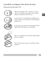
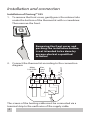
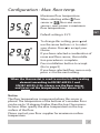
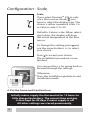
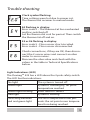
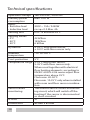
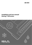
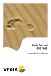
INT
Devireg™ 535
Installation manual
Warning!
This manual is only to be used by a
professional installer to install and
set up the thermostat properly.
It is not intended for the end-user!
Congratulations with…
... your DEVI floor heating system.
Your property has been installed with a DEVI electric floor
heating system. DEVI is Europe’s leading floor heating manufacturer, with over 45 years experience. We are confident
that you will be satisfied with your new system.
DEVI brings you…
An Invisible heating solution - A concealed heat source
opens up greater opportunities for decorating and furnishing.
Optimum comfort - DEVI brings you the luxury and comfort
of a warm floor as well as a pleasant room temperature.
Floor heating is the most comfortable type of heating
because it is based on the fact that warmth travels upwards;
pleasant warmth for your feet, body and head.
Low running costs – Thanks to the precise DEVI thermostat
and the placement of the heating elements right under the
floor surface the heat can be controlled optimally in order
for you to have the comfort you desire with minimal energy
use. Moreover electric floor heating is practically maintenance free, in total keeping down the running costs.
A long lasting solution - We back-up our floor heating solutions with a ten year guarantee on all our mats and cables,
and a two year warranty on our thermostats. Practically
speaking you can count on DEVI heating cables and mats
lasting as long as the house in which they are installed – and
that is without having to maintain them.
Hygiene - As DEVI produce floor heating systems, only very
gentle air is circulating, and the amount of travelling dust
particles is reduced considerably; a great relief for people
with allergies or asthma. There are also no dangerous fumes
such as carbon monoxide generated by the system.
2
Install & configure the thermostat
Placement of Devireg™ 535
When Devireg™ 535 is used as a room
sensor, installation height should typically be between 80-150 cm.
INT
In wet rooms it should be installed on an
even surface, according to local building
regulations.
At least 50 cm away from windows/doors
that will be left open occasionally.
Not on a wall where it will be subjected to
direct sunlight.
Not on the inner side of a wall facing the
outside.
3
Installation and connection
Installation of Devireg™ 535
1. To remove the front cover, gently press the release tabs under the bottom of the thermostat with a screwdriver. Then remove the front.
Removing the front cover and
pushing the installation button,
is not intended to be done by
anyone else but a qualified
installer!
Max.
Load
15 A
NO
CONNECT
Mains
180-250V~
NL
Sensor
2. Connect the thermostat according to the connection
diagram
N
L
N Load L Load NTC
The screen of the heating cable must be connected via a
terminal strip to the earth wire of the supply cable.
4
Choose sensor combination
3.
Choose sensor combination
When installing the Devireg™ 535 you need to choose
the type of heating and thus which sensors should be used. You have three options:
Comfort heating: Constant temperature on the floor in INT
bathrooms and other rooms where a comfortable warm
surface is required.
Install the Floor sensor and choose only the Floor sensor.
Total heating: Control of room temperature in living
rooms etc. Install the Floor sensor and choose both
Floor sensor and Room sensor.
No floor sensor: A floor sensor is not present, and
cannot be installed. Choose Room sensor. (Not recommended).
Be aware that without a floor sensor, the temperature control can be less accurate, and overheating of the floor is of higher risk.
DEVI recommends that a floor sensor is always
installed.
When the thermostat is used to control a floor heating
element according to EN/IEC 60335-1 and
EN/IEC 60335-2-96, always use the floor sensor
and never set the temperature limit above 35°C.
5
Configuration - sensor
Selection of sensor type
Power on the thermostat.
With the front off, with a small screwdriver, pencil, or needle press the
installation button.
Select the sensors to be used for the
heating system:
DeviregTM 535 is able to use two
sensors:
- a built-in room sensor
- an external sensor to be placed in the floor.
This gives 3 options:
floor sensor.
room sensor.
both room and floor sensor.
Always use floor sensor or a room
+ floor sensor combination when
used to control floor heating
The default is
To change this setting, press • and
use the arrow buttons ▲▼ to select
your choice. Press • to accept your
choice.
If you have selected room sensor
only, the installation procedure is
complete. Press installation button
to accept. (Go to page 9).
If you have selected floor sensor or a
combination of room- and floor sensor press ▲▼ for the next setting.
6
Configuration - Max. floor temp.
Maximum floor temperature.
When selecting either floor
sensor or
floor and room
sensors, next screen is maximum
floor temperature.
INT
Default setting is 35°C.
To change this setting, press • and
use the arrow buttons ▲▼ to select
your choice. Press • to accept your
choice.
If you have selected a combination of
room and floor sensor, the installation procedure is complete.
Press installation button to accept.
(Go to page 9)
If you have selected floor sensor only
press ▲▼ for the next setting.
When the thermostat is used to control a floor heating
element according to EN/IEC 60335-1 and
EN/IEC 60335-2-96, always use the floor sensor
and never set the temperature limit above 35°C.
Notice:
The floor temperature is measured where the sensor is
placed. The temperature of the bottom of a wooden floor
can be up to 10 degrees higher than the top. Floor manufactures often specify the max. temperature on the top
surface of the floor.
Please contact your floor supplier for maximum surface
temperature.
7
Configuration - Scale
Scale
If you select DeviregTM 535 to only
use a floor sensor, mode , you
have to select the display type. The
choice is either numerical scale 1-6
or Celcius scale 5° to 45°.
Default is Celcius scale. When selecting Celcius, the display will show
the actual temperature at the floor
sensor.
To change this setting, press • and
use the arrow buttons ▲▼ to select
your choice.
Press • to accept your choice.
The installation procedure is now
finished.
You can use the ▲▼ for going back or
forward through the settings.
Otherwise:
Press the installation pinhole to exit
installation mode.
4. Put the frame and front back on.
Initially mains supply the thermostat for 15 hours to
fully charge the battery. The current time and day
is then kept for 80 days if mains supply is off.
All other settings are stored permanently.
8
Trouble shooting
Clock symbol flashing:
Time settings were lost due to power cut.
The thermostat resumes to manual mode.
E4 flashing in display:
Error code 4 – The thermostat has overheated
and has switched off
Let the thermostat cool for period. Then switch
the thermostat off and on.
E5 or E6 flashing in display:
Error code 5 - Floor sensor short circuited.
Error code 6 - Floor sensor disconnected.
Check connections, if they are OK, then disconnect the 2 sensor wires and connect an ohm
meter to sensor wires.
Measure the ohm value and check with the
values in the table in Technical Specifications
below.
Light Indications (LED)
The DeviregTM 535 has a LED above the 2 pole safety switch.
The LED has five indications:
No light
Green light
Green light flashing
Red light
Switching between
red and green light
The system is turned off.
System is standing by, set point
temperature reached
Floor sensor is defect
System is heating
The floor temperature limit prevents the set point room temperature from being reached.
9
INT
Technical specifications
Operation voltage
Standby power
consumption
Relay:
• Resistive load
• Inductive load
Sensing unit
Sensing values:
• 0°C
• 20°C
• 50°C
Hysteresis
180-250 VAC, 50/60 Hz
Max. 0.30 W
230V ~ 15A / 3450W
cos φ= 0.3 Max. 4A
NTC 15 kOhm at 25°C
42 kOhm
18 kOhm
6 kOhm
± 0.2°C with room sensor,
± 0.4°C with floor sensor only
-10° to +30°C
Ambient
temperature
Frost protection
5°C
Temperature range 5-35°C with room sensor,
5-45°C with floor sensor only.
When used together with electrical
floor heating elements, according to
EN/IEC 60335-2-96 never adjust floor
temperature above 35°C.
Floor max. 20-50°C.
Floor min. 10-35°C only when installed
with room and floor sensor combination.
Sensor failure
The thermostat has a built-in monitormonitoring
ing circuit, which will switch off the
heating if the sensor is disconnected
or short-circuited
IP class
31
Dimensions
85 mm x 85 mm
10
Disposal Instruction
INT
11
Article No.: 08095880
VICKI302
DEVI A/S
Ulvehavevej 61
DK-7100 Vejle
Tel: +45 74 88 85 00
Fax: +45 74 88 85 01
www.devi.com
06/2010
Version - 02