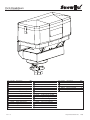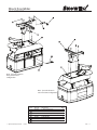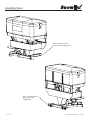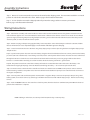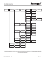
1
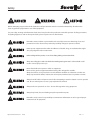
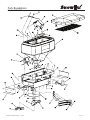
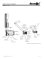
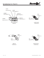
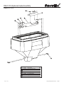
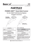
This Manual Must Be Read Before Operating The Equipment
Owner / Operator’s Manual
Spreaders for Snow & Ice Control
FOR MODEL
BULK PRO -1575
p
Warm U
to
with a
F R E Eand!
Winter
k Page
See Bac
B
ails!
for Det
CUSTOMER COPY
Warren, Michigan 48089
© Trynex International 2010 (REV 003)
Protected by the following patents, #6,089,478, #6,088,865, #Des.425,915
and other pending U.S. and foreign patent applications.
L1265
P15 — 1
Table of Contents
INTRODUCTION . . . . . . . . . . . . . . . . . . . . . . . . . . . . . . . . . . . . . . . . . . . . . . . . . . . . . . . . . . . . . . . . . . . . . . . . . . . . . . . . . . . . . . . . . . . . . . 3
GENERAL INFORMATION AND REGISTRATION . . . . . . . . . . . . . . . . . . . . . . . . . . . . . . . . . . . . . . . . . . . . . . . . . . . . . . . . . . . . . . . . . 4
SAFETY . . . . . . . . . . . . . . . . . . . . . . . . . . . . . . . . . . . . . . . . . . . . . . . . . . . . . . . . . . . . . . . . . . . . . . . . . . . . . . . . . . . . . . . . . . . . . . . . . . 5 - 6
• PREPARATION
• OPERATIONS
• SERVICE
SPREADER PARTS/DIAGRAMS . . . . . . . . . . . . . . . . . . . . . . . . . . . . . . . . . . . . . . . . . . . . . . . . . . . . . . . . . . . . . . . . . . . . . . . . . . . . 7 - 10
WIRING AND INSTALLATION INSTRUCTIONS . . . . . . . . . . . . . . . . . . . . . . . . . . . . . . . . . . . . . . . . . . . . . . . . . . . . . . . . . . . . 11- 15
OPERATING THE SPREADER . . . . . . . . . . . . . . . . . . . . . . . . . . . . . . . . . . . . . . . . . . . . . . . . . . . . . . . . . . . . . . . . . . . . . . . . . . . . . 16 - 18
TROUBLESHOOTING . . . . . . . . . . . . . . . . . . . . . . . . . . . . . . . . . . . . . . . . . . . . . . . . . . . . . . . . . . . . . . . . . . . . . . . . . . . . . . . . . . . . 19 - 20
SPREADER MAINTENANCE . . . . . . . . . . . . . . . . . . . . . . . . . . . . . . . . . . . . . . . . . . . . . . . . . . . . . . . . . . . . . . . . . . . . . . . . . . . . . . . . . . 21
WARRANTY . . . . . . . . . . . . . . . . . . . . . . . . . . . . . . . . . . . . . . . . . . . . . . . . . . . . . . . . . . . . . . . . . . . . . . . . . . . . . . . . . . . . . . . . . . . . . . . . . 22
WARRANTY CARD . . . . . . . . . . . . . . . . . . . . . . . . . . . . . . . . . . . . . . . . . . . . . . . . . . . . . . . . . . . . . . . . . . . . . . . . . . . . . . . . . . . . . . . . . . 23
Have a question or need assistance?
SnowEx Customer Service
(800) 725-8377
or (586) 756-6555
Monday through Friday 8:00 AM to 4:30 PM EST
Fax: (586) 427-0552
E-Mail: [email protected]
Website: www.snowexproducts.com
P15 — 2
© Trynex International 2010
L1265
Introduction
This manual has been designed for your help. It will assist you and instruct you on the proper set-up, installation and use of
this spreader. Refer to the table of contents for an outline of this manual.
We require that you read and understand the contents of this manual completely (especially all safety information) before
attempting any procedure contained herein. Extra copies of Owner/Operator Manuals can be purchased at your Snowex Dealer.
THIS SIGN SHOULD ALERT YOU:
The Society of Automotive Engineers has adopted this SAFETY ALERT SYMBOL to pinpoint characteristics
that, if NOT carefully followed, can create a safety hazard. When you see this symbol in this manual or on the
machine itself, BE ALERT! Your personal safety and the safety of others is involved.
Defined below are the SAFETY ALERT messages and how they will appear in this manual:
(RED)
Information that, if not carefully followed,
can cause death!
(ORANGE)
Information that, if not carefully followed,
can cause serious personal injury or death!
(YELLOW)
Information that, if not carefully followed,
can cause minor injury or damage to equipment.
© Trynex International 2010 L1265
P15 — 3
General Information
CONGRATULATIONS!
The spreader you have purchased is an example of snow and ice control technology at its
self-contained design is a trademark of all Snowex products. Here’s why...
Your spreader’s
SIMPLICITY: Fewer moving parts manufactured of higher quality means minimal maintenance for your SnowEx spreader.
RELIABILITY: High impact linear low density polyethelyne hopper, state-of-the-art electronic dual variable speed control, custom
engineered powder coated frame, maximum torque 12 volt motor coupled to a custom engineered transmission found only
on SnowEx products.
VERSATILITY: Multi-use capabilities allows spreading of a variety of materials for snow and ice control.
WARRANTY: Best in the industry, hands down! 2 years standard and now 5 year extended (optional).
The
you are about to recognize are that of time, money and
We welcome you to the world of Snowex Performance.
.
Registration
Record the following information in this manual for quick reference.
Spreader Model Number _____________________________________________________________________________________
Spreader Serial Number ________________________________
Controller Serial Number _______________________________
Date of Purchase ___________________________________________________________________________________________
Dealer Where Purchased _____________________________________________________________________________________
When ordering parts, the above information is necessary. This will help to insure
that you receive the correct parts.
At the right is a diagram of the ID tag. This tag on the spreader is located
on the frame.
Please
out the warranty card with all the necessary information to validate it. This will also give us a record so that
any safety or service information can be communicated to you.
P15 — 4
© Trynex International 2010
L1265
Safety
Before attempting any procedure in this book, these safety instructions must be read and understood by all workers who
have any part in the preparation or use of this equipment.
For your safety , warning and information decals have been placed on this product to remind the operator of safety precautions.
If anything happens to mark or destroy the decals, please request new ones from Snowex.
Remember, most accidents are preventable and caused by human error. Exercising of care and
precautions must be observed to prevent the possibility of injury to operator or others!
Never operate equipment when under the influence of alcohol, drugs, or medication that might
alter your judgment and/or reaction time.
Before working with the spreader, secure all loose fitting clothing and unrestrained hair.
Always wear safety glasses with side shields when working metal against metal. Failure to do this could
result in serious injury to the eyes.
Never allow children to operate or climb on equipment.
Never weld or grind on equipment without having a fire extinguisher available.
Always check areas to be spread to be sure no hazardous conditions or substances are in the area.
Always inspect unit for defects: broken, worn or bent parts, weakened areas on spreader or mount.
Always shut off vehicle and power source before attempting to attach or detach or service spreader
unit. Be sure vehicle/power source is properly braked or chocked.
Always make sure personnel are clear of areas of danger when using equipment.
Always keep hands, feet, and clothing away from power-driven parts.
Remember, it is the owner’s responsibility to communicate information on safe usage and proper
maintenance of all equipment.
© Trynex International 2010
L1265
P15 — 5
Safety Precautions
Never exceed 45 m.p.h. when loaded spreader is attached to vehicle. Braking distances may be
increased and handling characteristics may be impaired at speeds above 45 m.p.h.
Never use wet materials, or materials with foreign debris in the SP-1575. This unit is designed to
handle dry, clean, free-flowing material. Note: Can not spread water softener salt.
Never leave material in hopper for long periods of time. Be aware that all ice melters are hygroscopic
and will attract atmospheric moisture and harden up.
Always inspect pins, and latches whenever attaching or detaching spreader, and before traveling.
Inspect the unit periodically for defects. Parts that are broken, missing, or worn out must be replaced
immediately. The unit, or any part of it can not be altered without prior written permission from the
manufacturer.
Examples of warning decals to indicate operational awareness.
P15 — 6
D 6546
D 6547
D 6545
D 6544
D 6335
D 6548
© Trynex International 2010
L1265
Parts Breakdown
Model # SP-1575
© Trynex International 2010
L1265
P15 — 7
Parts Breakdown
Model # SP-1575
Key Part No.
D6240
D6257
D5114
D5110
D5105
D6140
D5115
D5100
D6174
D5102
D6320
D6566
D5107
D5120
D6327
P15 — 8
Description
Qty. Key Part No.
1575 Lid Assembly
1
D6750
1
1575 Top Screen
D6746
1
1 Pc. Material Baffle
D5140
1
Vibrator Inverted Vee
D5138
1
10” Auger Assembly
D6131
D6232
5/16-18 x 1/2 Set Screw 1
1
5/8 USS Nylon Washer
D6107
1
D6172
1575 Yellow Hopper
DC-80 Vibrator
1
D6512
1
D6584
1575 Main Frame
Auger & Spinner Motor 2
D6130
1
D6874
Auger Transmission
D4123
1
Auger Motor Cover
1
D4121
Plastic Material Chute
1
D4125
Plastic Deflector
Description
Qty. Key Part No.
D5706
1
4 Flite Plastic Spinner
1
D6166
Ball Detent Pin
1
D6137
Spinner Motor Cover
D4122
1
Plastic CE Guard
8
D5103
1/4-20 Serr. Hex Bolt
2
Motor Trans Coupler
1
Spinner Transmission
4
10/32 x 5/8 Serr Flg Bolt
1
Auger Bearing W/Cap
12
3/8 Serrated Flg Nut
12
3/16 Blk Alum Rivet
1
1/4 x 1-1/2 Self Driller
1/2-13 x 1-1/2 HH
1
6
3/8-16 x 1 Hex Head
6
3/8 Flat Washer
Description
Qty.
4
5/16-18 Serr. Hex Nut
2
5/16-18 x 1 Hex Bolt
5/16-18 x 1-1/4 PH Screw 2
4
3/8-16 x 1/1/2 HH
Spreader Stand
1
© Trynex International 2010
L1265
Mount Assemblies
Model # SP-1575
Note: Spreader shown in
three point mount
configuration
Note: Spreader shown in
reciever mount configuration
Key
© Trynex International 2010
L1265
Part No.
D5104
D4116
D4120
D4133
D5121
D4136
D4135
Description
2” Receiver Mount
1/2-13 x 1 Hex Head Bolt
1/2-13 Lock Nut (not shown)
5/16” Lynch Pin
7/8 Clevis Pin
Hitch Pin
Hair Pin Clip
Qty.
1
4
4
2
2
1
1
P15 — 9
Assembly Views
Model # SP-1575
Note: Spreader shown in
reciever mount configuration
Note: Spreader shown in
three point mount
configuration
P15 — 10
© Trynex International 2010
L1265
Assembly Instructions
Model # SP-1575
Step 1. Reverse 2” receiver mount when you remove the unit from the shipping carton. The mount was installed in a reversed
position in order for the unit to fit in the carton. Refer to page 10 for illustration information.
Step 2. You can leave the mount in the shipped position if you intend on using speader on a tractor 3 point mount.
Refer to page 10 for illustration information.
Wiring Instructions
Step 1: Take harness assembly and route from the rear of the vehicle to the front. Route harness along frame and attach to frame
holes and frame supports. It is not recommended to attach to fuel or brake lines for obvious reasons. Do not route close to exhaust
system or engine, even though Trynex uses high temperature wiring. It still could melt under extreme heat and short the spreader
electrical system, as well as the vehicle electrical system.
Step 2: Mount rear plug on bumper using supplied bolts, locate towards the center of the bumper to reduce the amount of debris
the tires will throw to the rear. Important: Apply a small amount of dielectric grease to the plug.
Step 3: Secure harness from the rear to the front using heavy duty ty-wraps or frame clips along the frame and lighter duty ty-wraps
everywhere else.
Step 4: Layout harness portion that connects to the battery along the fire wall and fender well. Do not connect power leads to battery
yet. Drill a 3/4" hole in the fire wall, or use existing access hole, for the control portion of the harness and route connector and harness
through hole. Be sure to check the area on the other side of the fire wall to make sure you are not going to drill into the vehicle
harness or a control module. Generally you can drill on either side of the steering column for a good location.
Step 4A: The power harness from control box to battery will need to be routed from the inside of the cab to the battery – this
results from the large high amperage connector. Route leads with lugs to battery — do not connect power at this time.
Step 5: Connect harness to the back of the controller and mount to a suitable location. NOTE: You may want to contact customer
before mounting controller, some prefer not to have holes drilled into the dashboard. Ty-wrap loose controller harness and move to
the engine compartment.
Step 6: Connect power leads to the battery: Red + Positive, Black – Negative. Always connect to the primary battery if using a dual
battery system, secure loose loom to any other large or medium vehicle harness with medium duty ty-wraps. This will secure wiring
harness.
Step 7: Push the ON/OFF button on the controller to check for power, when that has been confirmed turn power OFF. The electrical
portion of the installation is complete.
NOTE: If adding an inline fuse, use a 60 amp slow blow (time delay) or a 60 amp relay.
© Trynex International 2010
L1265
P15 — 11
Electrical System Parts Breakdown
Model # SP-1575
To Vibrator
To Auger Motor
To Spinner Motor
Anderson Block
Key
Special Notes:
1. All external connections must have dielectric grease.
2. Read lead labels before attaching to power source or ground.
3. No other devices may be spliced into wiring harness.
4. Any repairs to wiring harness must be done with heat shrink
butt connectors.
5. If inline fuse is installed, use a 60 amp maxi fuse or circuit breaker.
P15 — 12
Par t No.
D 6527
D 6124
D 6329
D 6341
D 6322
Des c r iption
Controller
Bracket Knob
Controller Bracket
Control Power Cable
Wiring Harness - 25'
D 6343
D 6170
D 6237
D 6354
D 6344
Dust Cover
Anderson Connector With Leads
5 Terminal Control Power Switch
3 Terminal Vibrator Switch
Dielectric Grease - 1 1/2 oz. (not shown)
© Trynex International 2010
Qty.
1
2
1
1
1
1
1
1
1
1
L1265
Vehicle Harness Diagram
Model # SP-1575
Anderson
Block
(2) Pos
CONTROL
OUTPUT PLUG
BUMPER
PLUG
SPINNER/AUGER
Anderson
CIRCUIT
Block
(4) Pos
VIBRATOR
White Positive (+)
AUGER OUTPUT
(housing)
Red Positive (+)
Red Wire
VIBRATOR
Black Negative (–)
SPINNER
White Positive (+)
AUGER
Red Positive (+)
SPINNER
Black Negative (–)
AUGER
Green Negative (–)
SPINNER OUTPUT
(housing)
Red Positive (+)
White Wire
AUGER OUTPUT
(housing)
Black Negative (–)
Green Wire
VIBRATOR
CIRCUIT
OUTPUT
Red
Positive (+)
White Wire
Black
Negative (–)
Black Wire
SPINNER OUTPUT
(housing)
Black Negative (–)
Black Wire
* NOTE: Reference Bumper Plug for Color Code
© Trynex International 2010
L1265
P15 — 13
Spreader Harness Diagram
Model # SP-1575
AUGER
Red Positive (+)
AUGER
Green Negative (–)
SPINNER
Black Negative (–)
VIBRATOR
Black Negative (–)
VIBRATOR
White Positive (+)
SPINNER
White Positive (+)
Black
Negative (–)
Red
Positive (+)
AUGER POWER
CONNECTION
MAIN POWER PLUG
SPREADER
White
Positive (+)
Black
Negative (–)
VIBRATOR
POWER PLUG
P15 — 14
Black
Negative (–)
Red
Positive (+)
SPINNER POWER
CONNECTION
© Trynex International 2010
L1265
Control Wiring Diagram
Model # SP-1575
Vibrator
Red Positive (+)
Vibrator
Black Negative (–)
OUTPUT
Black
Negative (–)
INPUT
Auger
Red Positive (+)
Spinner
Red Positive (+)
Auger
Black Negative (–)
Red
Positive (+)
D6341 Control Power Cable
Spinner
Black Negative (–)
M O A
a p
a
p
vo
a a
o
p
a ag
ov
o
bo
o
Negative
Black (–) to battery
Ring Terminal
Positive
White with Red Tracer (+) to battery
Ring Terminal
Connect to control
mating half
* NOTE:
A) Leads must only be attached to battery.
B) If fusing, must use minimum 60 Amp
Maxi type fuse or circuit breaker.
© Trynex International 2010
L1265
P15 — 15
Operating Instructions
Model # SP-1575
PREPARATION
CAUTION – Sweep area clear of foreign objects or obstacles that could cause personal injury. Keep other persons, children, or animals
out of the area to be spread.
SPREADER LOADING
WARNING –Do not overload vehicle. Use chart below to calculate weight of material. Weights of material are an average for dry materials
Material
Weight Per Cubic Ft.
Rock Salt
35-40 lbs.
Sand/Salt Mix
95-120 lbs.
•
•
Be sure to comply with manufacturer’s maximum gross vehicle weight ratings.
Warning– Never leave materials in hopper for long periods of time as salt is hygroscopic and will attract atmospheric moisture
and harden up. When spreading sand mix, a 1:1 ratio for Sand/Salt mix is recommended to prevent the material from freezing.
SPREADING TIPS
•
Never exceed 10 m.p.h. when spreading.
•
For a wider pass, increase spinner speed.
•
For a heavier pass, drive slower, or increase auger speed.
•
Never operate spreader near pedestrians.
•
Spread ice melters with the storm to prevent unmanageable levels of ice.
•
Calculate spread pattern when near vegetation.
P15 — 16
© Trynex International 2010
L1265
Operating the Spreader
Model # SP-1575
BULK PRO 1575
•
The Dual Variable Speed Control has dual finger-tip dials for maximum performance, digital system status with warning protection
and built-in Vibrator Switch.
•
To start, press power switch on controller and spreader will accelerate to speed set on spinner and auger dials.
•
To stop, press power switch on controller to off position.
•
Speed of auger and spinner may be adjusted separately to get desired flow and spread distance
from spreader.
•
The Vibrator Switch is needed for dense material or to increase the flow to the auger. This eliminates bridging of material in hopper.
•
A Material Baffle has been installed in your spreader to stop fine material from free-flowing. If using dense or damp
material, or if more flow is desired, remove Material Baffle. However, it is recommended that the Material Baffle remain in place if
using bulk salt.
AUTO-REVERSE “AR” FUNCTION
• If your controller displays “OL” this could indicate a jammed auger.
• To engage the Auto-Reverse “AR” function:
Step 1: Shut the Main Power Switch OFF for 3 seconds.
Step 2: Turn the Main Power Switch ON. When the machine starts back up the “AR” sequence will automatically start and the auger
will reverse for several rotations to clear the jam.
• After a pause of several moments, the auger will automatically return to correct rotation.
• If the jam is still not cleared, the controller will again display “OL”.
• You may repeat Steps 1 & 2 for a second and third time.
• If after the third try the controller displays “OL” — you must extract the material that is causing the problem.
• Follow all warning directions when clearing jams.
WARNING PROTECTION
•
If audible beeping occurs, read display to identify problem. If display reads “OL” (overload) or “OH” (overheat), shut controller down
and carefully clear jammed auger. If display reads “E1“ this means there is a dead short in system. Do not use until problem is
corrected. If display reads “E0”, this means that the motor is not getting any power. Check all connections. If display reads “LB”, the
vehicle battery is extremely low and could damage system or a poor connection exists.
•
If there are any problems while operating the spreader, refer to Troubleshooting Guide.
© Trynex International 2010
L1265
P15 — 17
TRK-1575 (Optional) Gate Assembly
Model # SP-1575
Key Part No.
D 5209
D 5949
D 5112
D 5023
D 6449
D 5117
D 5113
P15 — 18
Description
5/16-18 X 3/4 SS HH
5/16 Flat Washer SS
End Cap
5/16 -18 Keps Nut
1/4-20 Wing Nut
Auger Tube
Gate Cover
Qty.
4
4
1
4
1
1
1
© Trynex International 2010
L1265
Troubleshooting
Model # SP-1575
SPREADER
DOES NOT RUN
TURNS ON
BEEP SHUTS OFF
DISPLAYS ERROR CODE
OL CODE
DEFINITION:
AMP DRAW
TOO HIGH
JAMMED MATERIAL
BAD MOTOR
CHECK WITH TEST KIT
SWITCH OFF & ON
FOR AUTO-REVERSE
FUNCTION
CLEAR JAM
TEST 4 TO 20 AMP DRAW
NO LOAD GOOD
20+ AMP DRAW
NO LOAD BAD
BAD TRANSMISSION
CHECK WITH TEST KIT
CORROSION
TEST TURN SHAFT
BY HAND
SHOULD TURN FREELY
REPLACE ALL
CORRODED
CONNECTIONS
GREASE
DON'T FORGET
USE DIELECTRIC
BAD CONTROLLER
CHECK WITH TEST KIT
EO CODE
DEFINITION:
OPEN CIRCUIT BETWEEN
MOTOR AND CONTROLLER
SPREADER UNPLUGGED
PLUG IN SPREADER
MOTOR POWER CORD
DISCONNECTED
INSIDE DRIVE ASSEMBLY
OPEN ACCESS COVER
AND PLUG TOGETHER
BREAK IN
WIRING HARNESS
LB CODE
ON/OFF SWITCH
LIGHTS NO DISPLAY
NOTHING HAPPENS
NO DISPLAY
ON/OFF SWITCH WILL
NOT LIGHT UP
BAD ELECTRICAL
CONNECTION
CORROSION
REPLACE ALL CORRODED
CONNECTIONS
LOOSE CONNECTION
TIGHTEN OR REPLACE
LOW BATTERY
LESS THAN 12 VOLT
OUTPUT
LOAD TEST BATTERY
E1 CODE
DEAD SHORT
IN MOTOR CIRCUIT
REPLACE
AFFECTED
COMPONENTS
ALL OTHER
CODES
CHECK HARNESS
FOR ANY SPLICED
IN ACCESSORIES
CHECK POWER
TO BLUE WIRE
CHECK POWER SOURCE
TO CONTROLLER
REPLACE HARNESS
CHECK WITH TEST KIT
BAD CONTROLLER
CHECK WITH TEST KIT
REPLACE
BAD CONTROLLER
CHECK WITH TEST KIT
BAD CONTROLLER
CHECK WITH TEST KIT
SNOWEX DIAGNOSTIC TEST KIT (STK-020) IS AVAILABLE TO ACCURATELY DIAGNOSE ANY ISSUES WITH SNOWEX SPREADERS.
CALL YOUR DEALER FOR DETAILS.
© Trynex International 2010
L1265
P15 — 19
Troubleshooting Material Flow
Model # SP-1575
MATERIAL
FREE FLOWS
MATERIAL
DOES NOT FLOW
CHECK BAFFLE
LENGTH
18" CORRECT
MATERIAL ISSUE
CHECK BAFFLE
POSITION
SHOULD TOUCH HOPPER
ON 3 SIDES
MATERIAL ISSUE
MATERIAL
OBSTRUCTION
AUGER RUNS
BACKWARDS
TURN ON
VIBRATOR
SLOW
MATERIAL
FLOW
REMOVE
OBSTRUCTION
RUN 12 VOLT TO
AUGER CIRCUIT ON
SPREADER POWER CORD
MATERIAL ISSUE
AUGER RUNS
PROPER DIRECTION
AUGER RUNS
BACKWARDS
REPLACE VEHICLE
HARNESS
CHECK CONNECTIONS
AT AUGER MOTOR
FOR REVERSE POLARITY
POLARITY CORRECT
REPLACE SPREADER
HARNESS
TURN ON
VIBRATOR
INCREASE
AUGER SPEED
MATERIAL ISSUE
P15 — 20
© Trynex International 2010
L1265
Spreader Maintenance
•
A
G – When servicing is necessary, perform it in a protected area. Do not use power tools in rain or snow because of
danger of electrical shock or injury. Keep area well lighted. Use proper tools. Keep the area of service clean to help avoid
accidents.
•
A
G – Disconnect electricity to spreader before servicing.
•
C
– The controller is a solid state electronic unit and is not serviceable. Any attempt to service will void warranty.
•
C
– There are no serviceable parts in the motor/transmission assembly. Any attempt to service will void warranty.
•
C
– When replacing parts, use only original manufacturer’s parts. Failure to do so will void warranty.
•
Use dielectric grease on all electrical connections to prevent corrosion at the beginning and end of the season and each
time power plugs are disconnected.
•
Wash unit after each use to prevent material build-up and corrosion.
•
C
•
Paint or oil all bare metal surfaces at the end of the season.
•
If motor cover is removed for any reason, use silicone sealant to ensure weather proofing of enclosure.
•
After first use, tighten all nuts and bolts on spreader and mount.
•
A EN ON Store control in cool dry place during the off season.
•
CA
– When pressure washing motor enclosure area, stay at least 36'' away from motor enclosures.
O – Spinner motor is not designed for continuous duty. Allow motor to cool between long cycle times.
© Trynex International 2010
L1265
P15 — 21
Warranty
Limited Warranty
Snowex products are warranted for a period of two years from the date of purchase against
defects in material or workmanship under normal use and service, subject to limitations detailed
below. Warranty period of two years begins on the date of purchase by the original retail user.
The WARRANTY REGISTRATION CARD must be returned to the manufacturer for this warranty
to become effective. This warranty applies to the original retail purchaser only. This warranty does
not cover damages caused by improper installation, misuse, lack of proper maintenance, alterations
or repairs made by anyone other than authorized Snowex dealers or Snowex personnel. Due to the
corrosive properties of the materials dispensed by spreaders, Trynex does not warrant against
damage caused by corrosion. Warranty claims by the user must be made to the dealer from where
the product was purchased, unless otherwise authorized by Snowex. Snowex reserves the right to
determine if any part is defective and to repair or replace such parts as it elects. This warranty does
not cover shipping costs of defective parts to or from the dealer.
LIMITATION OF LIABILITY
Neither Snowex, nor any company affiliated with it, makes any warranties, representations for
promise as to the performance or quality other than what is herein contained. The liability of Snowex
to the purchaser for damages arising out of the manufacture, sale, delivery, use or resale of this
spreader shall be limited to and shall not exceed the costs of repair or replacement of defective
parts. Snowex shall not be liable for loss of use, inconvenience or any other incidental, indirect or
consequential damages, so the above limitations on incidental or consequential damages may not
apply to you.
NO DEALER HAS AUTHORITY TO MAKE ANY REPRESENTATION OR PROMISE ON BEHALF OF
SNOWEX, OR TO ALTER OR MODIFY THE TERMS OR LIMITATIONS OF THIS
WARRANTY IN ANY WAY.
P15 — 22
© Trynex International 2010
L1265
Warranty Registration and Customer Survey
To initiate the warranty on your new SnowEx spreader and assure prompt warranty service, please complete the
following warranty registration and customer survey, sign and mail it back to the factory within 30 days of purchase.
1)
Date of Purchase:
2)
Name:
Address:
Phone:
3)
S nowE x M ode l P urc ha s e d:
4)
5)
S e ria l N umbe r:
Trynex Spreader?
Yes
No
What type of vehicle are you using with your Spreader?
M ake
M ode l
6)
What type of material are you using in your spreader?
7)
SnowEx Dealer Name:
Ye a r
SnowEx Dealer Address:
SnowEx Dealer Phone:
Yes
No
I don’t know
8)
Does your Trynex Dealer stock Trynex replacement Parts?
9)
Do you feel your Trynex Dealer sold you the correct product for your needs/application?
10) How would you rate
your overall satisfaction
with your SnowEx Dealer?
S
11) How would you rate
your overall satisfaction
with your SnowEx Product?
S
Very
Very
12) Would you purchase another Trynex Product?
Yes
No
d
d
Somewhat
d
Somewhat
d
Dissatis d
d
d
Somewhat
d
Somewhat
d
Dissatis d
Yes
Very
Very
d
d
No
13) If you would like to receive E-Mail ALERTS for new products, bulletins or special promotions please supply address : _________________________________________________
14) Please use the space below to convey your comments and/or suggestions.
NOTE: I have read the owner’s manual and all safety precautions and I understand that this equipment could be dangerous if not operated
with care and under the proper conditions.
15) Owner’s signature:
X
PLEASE FOLD AND SEAL WITH TRANSPARENT TAPE BEFORE MAILING.
© Trynex International 2010
L1265
P15 — 23
Warm Up to
with a
FREE
Winter Band!
Simply Fill Out Your
Warranty Registration and
Return It to the Factory!
From:
Postage
Required
Post Office will
not deliver
without proper
postage.
23455 REGENCY PARK DR.
WARREN MI 48089-2667