1
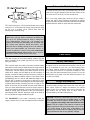
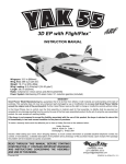
™
INSTRUCTION MANUAL
Wingspan: 20.5 in [514mm]
Wing Area: 235 sq in [15.2dm2]
Weight: 7.4 – 8.0 oz [210 – 225g]
Wing Loading: 4.5 – 4.9 oz/sq ft [14 – 15g/dm2]
Length: 22.75 in [580mm]
Radio: 4-channel with 3 micro servos
Motor: RIMFIRE™ 28-22-1380kV brushless out-runner
™
WARRANTY
Great Planes® Model Manufacturing Co. guarantees this kit to be free from defects in both material and workmanship at the date of
purchase. This warranty does not cover any component parts damaged by use or modification. In no case shall Great Planes’ liability
exceed the original cost of the purchased kit. Further, Great Planes reserves the right to change or modify this warranty without notice.
In that Great Planes has no control over the final assembly or material used for final assembly, no liability shall be assumed nor
accepted for any damage resulting from the use by the user of the final user-assembled product. By the act of using the user-assembled
product, the user accepts all resulting liability.
If the buyer is not prepared to accept the liability associated with the use of this product, the buyer is advised to return this
kit immediately in new and unused condition to the place of purchase.
To make a warranty claim send the defective part or item to Hobby Services at the address below:
Hobby Services
3002 N. Apollo Dr., Suite 1
Champaign, IL 61822 USA
Include a letter stating your name, return shipping address, as much contact information as possible (daytime telephone number, fax
number, e-mail address), a detailed description of the problem and a photocopy of the purchase receipt. Upon receipt of the package
the problem will be evaluated as quickly as possible.
READ THROUGH THIS MANUAL BEFORE STARTING
CONSTRUCTION. IT CONTAINS IMPORTANT INSTRUCTIONS
AND WARNINGS CONCERNING THE ASSEMBLY AND
USE OF THIS MODEL.
Entire Contents © Copyright 2006
Champaign, Illinois
(217) 398-8970, Ext 5
[email protected]
GPMZ1570 for GPMA1570/1571 V1.0
TABLE OF CONTENTS
AMA
INTRODUCTION ...............................................................2
AMA...................................................................................2
SAFETY PRECAUTIONS..................................................2
LITHIUM BATTERY HANDLING & USAGE .....................3
RADIO EQUIPMENT .........................................................3
ADDITIONAL ITEMS REQUIRED.....................................3
Adhesives & Building Supplies....................................3
Optional Supplies & Tools ...........................................3
IMPORTANT BUILDING NOTES ......................................4
COMMON ABBREVIATIONS............................................4
METRIC CONVERSIONS .................................................4
METRIC/INCH RULER ......................................................4
KIT INSPECTION ..............................................................5
KIT CONTENTS ................................................................5
ASSEMBLE THE FUSELAGE...........................................6
Install the Tail Surfaces................................................6
Mount the Wings .........................................................7
RADIO SYSTEM INSTALLATION.....................................9
Install the Servos & Pushrods .....................................9
Motor & ESC Installation ...........................................11
Battery & Receiver Installation ..................................12
ATTACH THE MAIN GEAR .............................................12
ATTACH THE PROPELLER ............................................13
APPLY THE DECALS......................................................13
GET THE MODEL READY TO FLY .................................13
Check the Control Directions ....................................13
Set the Control Throws..............................................14
Balance the Model (C.G.)..........................................14
Balance the Model Laterally......................................15
PREFLIGHT.....................................................................15
Identify Your Model ....................................................15
Charge the Batteries .................................................15
Balance the Propellers ..............................................16
Range Check.............................................................16
MOTOR SAFETY PRECAUTIONS .................................16
AMA SAFETY CODE (excerpts)....................................16
CHECK LIST ...................................................................17
FLYING ............................................................................17
Launch & Takeoff.......................................................17
Flight..........................................................................18
Landing......................................................................18
We urge you to join the AMA (Academy of Model
Aeronautics) and a local R/C club. The AMA is the governing
body of model aviation and membership is required to fly at
AMA clubs. Though joining the AMA provides many benefits,
one of the primary reasons to join is liability protection.
Coverage is not limited to flying at contests or on the club
field. It even applies to flying at public demonstrations and
air shows. Failure to comply with the Safety Code (excerpts
printed in the back of the manual) may endanger insurance
coverage. Additionally, training programs and instructors are
available at AMA club sites to help you get started the right
way. There are over 2,500 AMA chartered clubs across the
country. Contact the AMA at the address or toll-free phone
number below.
Academy of Model Aeronautics
5151 East Memorial Drive
Muncie, IN 47302
Tele: (800) 435-9262
Fax (765) 741-0057
Or via the Internet at:
http://www.modelaircraft.org
IMPORTANT!!! Two of the most important things you can do
to preserve the radio controlled aircraft hobby are to avoid
flying near full-scale aircraft and avoid flying near or over
groups of people.
PROTECT YOUR MODEL, YOURSELF
& OTHERS...FOLLOW THESE
IMPORTANT SAFETY PRECAUTIONS
1. Your Riot 3D ARF should not be considered a toy, but
rather a sophisticated, working model that functions very
much like a full-size airplane. Because of its performance
capabilities, the Riot 3D ARF, if not assembled and operated
correctly, could possibly cause injury to yourself or
spectators and damage to property.
INTRODUCTION
That’s a RIOT! That’s exactly what the people at the flying
field will say when this little bipe rockets skyward. With
Incredibly fast rolls, unlimited vertical, and amazing
acrobatics the Riot 3D ARF is sure to impress all who see it.
Note: There are two versions of the Riot 3D ARF available
– Transparent Yellow (GPMA1570), White (GPMA1571).
2. You must assemble the model according to the
instructions. Do not alter or modify the model, as doing so
may result in an unsafe or unflyable model. In a few cases
the instructions may differ slightly from the photos. In those
instances the written instructions should be considered
as correct.
For the latest technical updates or manual corrections to the
Riot 3D ARF visit the Great Planes web site at
www.greatplanes.com. Open the “Airplanes” link, and then
select the Riot 3D ARF. If there is new technical information
or changes to this model a “tech notice” box will appear in
the upper left corner of the page.
3. You must take time to build straight, true and strong.
4. You must use an R/C radio system that is in first-class
condition, and a correctly sized motor and components
(batteries, wheels, etc.) throughout the building process.
2
5. You must correctly install all R/C and other components so
that the model operates correctly on the ground and in the air.
RADIO EQUIPMENT
6. You must check the operation of the model before every
flight to insure that all equipment is operating and that the
model has remained structurally sound. Be sure to check
clevises or other connectors often and replace them if they
show any signs of wear or fatigue.
•
•
7. If you are not an experienced pilot or have not flown this
type of model before, we recommend that you get the
assistance of an experienced pilot in your R/C club for your
first flights. If you’re not a member of a club, your local hobby
shop has information about clubs in your area whose
membership includes experienced pilots.
•
•
•
•
8. While this kit has been flight tested to exceed normal use,
if the plane will be used for extremely high-stress flying,
such as racing, or if a motor larger than one in the
recommended range is used, the modeler is responsible for
taking steps to reinforce the high-stress points and/or
substituting hardware more suitable for the increased stress.
ADDITIONAL ITEMS REQUIRED
Adhesives & Building Supplies
We, as the kit manufacturer, provide you with a top quality,
thoroughly tested kit and instructions, but ultimately the
quality and flyability of your finished model depends on
how you build it; therefore, we cannot in any way
guarantee the performance of your completed model, and
no representations are expressed or implied as to the
performance or safety of your completed model.
This is the list of adhesives and building supplies that are
required to finish the Riot 3D ARF.
❏
❏
❏
❏
❏
❏
❏
❏
❏
Remember: Take your time and follow the instructions to
end up with a well-built model that is straight and true.
LITHIUM BATTERY HANDLING & USAGE
•
•
•
•
•
•
•
•
•
•
•
Great Planes Pro™ thin CA (GPMR6002)
Great Planes Pro medium CA (GPMR6008)
Hobbico® builder’s triangle (HCAR0480)
Hobbico hobby knife (HCAR0100)
#11 Blades for hobby knife (HCAR0211)
Top Flite® panel line pen (TOPQ2510)
Drill bits: 1/16" [1.6mm], 3/16" [4.8mm]
1/2" [13mm] Double-sided foam mounting tape (GPMQ4440)
1" [25mm] Double-sided foam mounting tape (GPMQ4442)
Optional Supplies & Tools
WARNING!! Failure to follow all instructions could cause
permanent damage to the battery and its surroundings, and
cause bodily harm!
•
4-channel radio with 3 micro servos such as the Futaba®
S3110M with micro plugs (FUTM0702)
R124F Micro Receiver (FUTL0438 for Low Band,
FUTL0439 for high band) with single conversion crystal
(FUTL62**) ** selects the channel for your receiver. For
example, if you wish to order a channel 35 crystal, you
would order FUTL6235
8A Micro Brushless ESC, such as Silver Series 8A
Brushless (GPMM1800)
RIMFIRE™ 28-22-1380kV Brushless Out-runner
Motor (GPMG4505)
APC 8x3.8 Slo-Flyer prop (APCQ5000)
350-640mAh 3-cell LiPo battery (GPMP0801 – 350mAh
3-cell, GPMP0805 – 640mAh 3-cell)
Here is a list of optional tools mentioned in the manual that
will help you build the Riot 3D ARF.
ONLY use a LiPo approved charger. NEVER use a
NiCd/NiMH peak charger!
NEVER charge in excess of 4.20V per cell.
ONLY charge through the “charge” lead. NEVER charge
through the “discharge” lead.
NEVER charge at currents greater than 1C.
ALWAYS set charger’s output volts to match battery volts.
ALWAYS charge in a fireproof location.
NEVER trickle charge.
NEVER allow the battery temperature to exceed 150° F [65° C].
NEVER disassemble or modify pack wiring in any way or
puncture cells.
NEVER discharge below 2.5V per cell.
NEVER place on combustible materials or leave
unattended during charge or discharge.
ALWAYS KEEP OUT OF REACH OF CHILDREN.
❏
❏
❏
❏
❏
❏
❏
❏
❏
❏
❏
❏
❏
❏
3
Hobbico covering iron (HCAR8000)
21st Century® trim seal iron (COVR2750)
Hobbico heat gun (HCAR7000)
Curved-tip canopy scissors for trimming plastic
parts (HCAR0667)
4 oz. [113g] Aerosol CA activator (GPMR634)
Stick-on segmented lead weights (GPMQ4485)
Small T-pins (100, HCAR5100)
2 oz. [57g] Spray CA activator (GPMR6035)
R/C-56 canopy glue (JOZR5007)
CA applicator tips (HCAR3780)
CA debonder (GPMR6039)
Hook & loop material (1" x 6" [25 x 150mm], GPMQ4480)
AccuThrow™ deflection gauge (GPMR2405)
Precision Magnetic Prop Balancer (TOPQ5700)
IMPORTANT BUILDING NOTES
METRIC CONVERSIONS
• When you see the term test fit in the instructions, it
means that you should first position the part on the
assembly without using any glue, then slightly modify or
custom fit the part as necessary for the best fit.
1" = 25.4mm (conversion factor)
1/64"
1/32"
1/16"
3/32"
1/8"
5/32"
3/16"
1/4"
3/8"
1/2"
5/8"
• Whenever the term glue is written you should rely upon
your experience to decide what type of glue to use. When a
specific type of adhesive works best for that step, the
instructions will make a recommendation.
• Photos and sketches are placed before the step they
refer to. Frequently you can study photos in following steps
to get another view of the same parts.
COMMON ABBREVIATIONS
Fuse
Stab
Fin
LE
TE
LG
Ply
"
mm
ESC
= Fuselage
= Horizontal Stabilizer
= Vertical Fin
= Leading Edge
= Trailing Edge
= Landing Gear
= Plywood
= Inches
= Millimeters
= Electronic Speed Control
4
=
=
=
=
=
=
=
=
=
=
=
.4mm
.8mm
1.6mm
2.4mm
3.2mm
4.0mm
4.8mm
6.4mm
9.5mm
12.7mm
15.9mm
3/4"
1"
2"
3"
6"
12"
18"
21"
24"
30"
36"
=
=
=
=
=
=
=
=
=
=
=
19.0mm
25.4mm
50.8mm
76.2mm
152.4mm
304.8mm
457.2mm
533.4mm
609.6mm
762.0mm
914.4mm
KIT INSPECTION
Before starting to build, take an inventory of this kit to make sure it is complete, and inspect the parts to make sure they
are of acceptable quality. If any parts are missing or are not of acceptable quality, or if you need assistance with assembly,
contact Product Support. When reporting defective or missing parts, use the part names exactly as they are written in
the Kit Contents list on this page.
Great Planes Product Support
3002 N. Apollo Drive, Suite 1
Champaign, IL 61822
Telephone: (217) 398-8970, ext. 5
Fax: (217) 398-7721
E-mail: [email protected]
KIT CONTENTS
2
1
8
5
3
6
9
7
4
11
10
12
10
13
14
16
15
Kit Contents (Not Photographed)
(1) Hardware Bag
(2) 12" [305mm] Carbon Rods
(4) 6" [153mm] Carbon Rods
(3) #2 x 3/8" [9.5mm] Self-tapping Screws
(3) #2 Flat Washers
(15) CA Hinges
(2) Wheel Pants
5
1.
2.
3.
4.
5.
6.
7.
8.
9.
10.
11.
12.
13.
14.
15.
16.
Kit Contents
Fuselage
Canopy
Landing Gear
Wheels (2)
Center Cabane
Tail Skid
Horizontal Stab & Elevator
Fin
Rudder
Wing Struts (L&R)
Bottom Wing
Left Bottom Wing Aileron
Right Bottom Wing Aileron
Top Wing
Left Top Wing Aileron
Right Top Wing Aileron
should be equal. Sand the slot in the rear of the fuse as
needed for a proper fit.
ASSEMBLE THE FUSELAGE
Install the Tail Surfaces
❏ 1. Locate the pre-hinged horizontal stab and elevator.
Measure and mark the center of the stabilizer as shown.
❏ 5. Using a piece of string, measure the distance from the
center of the nose of the fuselage to each of the stab tips.These
distances must be equal. Mark the stab where it enters the
fuselage. Trim the covering from the stab inside the marks.
❏ 6. Glue the stab in place once it is aligned with thin CA.
❏ 2. Carefully cut a slot for the elevator control horn in the
area marked on the sketch.
❏ 3. Insert the stab into the fuselage. Align the mark with
the centerline of the fuselage.
A=A
A
A
❏ 7. Locate the fin. Glue it in place along the centerline of
the fuselage as shown. The fin must be perfectly straight up
and down and at a 90° angle to the stabilizer.
❏
4. With the model sitting on a flat surface, measure the
distance from each stab tip to the surface. The measurements
6
Mount the Wings
❏ 8. Carefully cut a slot for the rudder control horn in the
area marked on the sketch.
❏ 1. Attach each of the ailerons to the wings using three
CA hinges.
❏ 9. Using three CA hinges, attach the rudder to the fin and
fuselage. Use three (3) drops of thin CA on each side of the
hinges. Wipe up any excess glue. DO NOT use accelerator
on the CA. This will cause the hinges to be very stiff and
possibly break.
❏ 2. On the bottom wing ailerons ONLY, carefully cut a slot
in the aileron for the control horn in the location shown in
the sketch.
❏ 10. Glue the tail skid in place along the centerline of the
fuselage as shown.
HOW TO CUT COVERING FROM BALSA
❏ 11. It is easiest to attach the canopy at this time. Later,
the wings may make canopy installation a little more difficult.
Attach the canopy using clear strips of tape or use canopy
glue. Do not use CA as this will distort the plastic or cause it
to “fog” over.
Use a soldering iron to cut the covering from the fin. The
tip of the soldering iron doesn’t have to be sharp, but a
fine-tip does work best. Allow the iron to heat fully.
Use a straightedge to guide the soldering iron at a rate
that will just melt the covering and not burn into the wood.
The hotter the soldering iron, the faster it must travel to
melt a fine cut. Peel off the covering.
7
❏ 3. Center the bottom wing in the wing saddle area as
shown using the same measuring technique as the stabilizer.
It may assist you to mark the centerline on the fuselage and
bottom wing with a felt-tip pen. Mark on the wing where it
meets the fuselage. Trim the covering inside the marks, and
then, glue the wing in place using medium CA. Be very
careful not to cut into the balsa.
❏ 5. Test fit the wing struts and center cabane as shown in
the photos above. Glue the wing struts in place as shown
using medium CA. Note the direction of the wing struts.
Insure the struts are parallel to the fuse.
❏ 6. Test fit the the top wing on the struts and center
cabane. Glue the top wing to the wing struts using medium
CA. Check that the top wing is parallel to the bottom wing.
❏ 4. Locate the two wing struts and center cabane. There
are slots in the top of the bottom wing, and the bottom of the
top wing for these wing struts to slide into. Carefully remove
the covering from these slots using a sharp hobby knife.
8
RADIO SYSTEM INSTALLATION
In the following sections, the hardware you will be using
will come from the included plastic parts trees.
Whenever possible, the part will have a number
associated with it and that number will be in
parentheses. For example, the Z-bend clevis part
number is A1 on the parts tree.
❏ ❏ 5. Install a Z-bend clevis (A1) in the last hole out on the
servo arm. If needed, enlarge the hole in the servo arm slightly
with a sharp hobby knife prior to attaching it to the servo.
Install the Servos & Pushrods
❏ ❏ 1. Carefully remove the film covering the servo bays
just behind the wings. Insert a servo with the spline toward
the tail as shown on both sides of the fuselage.
❏ ❏ 2. Glue the servo in place using medium CA.
❏ ❏ 6. Center all trims on your radio system and connect
the rudder servo to the rudder channel to center the servo.
Attach a servo arm (G6) as shown.
❏ ❏ 7. Locate a 12" [305mm] carbon rod and one pushrod
standoff (E3).
❏❏
3. Insert a Z-bend clevis (A1) into a control horn
(B1) as shown. It may be necessary to slightly enlarge the
hole in the control horn (B1) to allow the Z-bend clevis (A1)
to rotate freely. If necessary, use a sharp hobby knife to
enlarge the hole.
❏ ❏ 8. Slide one pushrod stand off onto the 12" [305mm]
❏ ❏ 4. Glue the control horn (B10) in place using medium
carbon rod. Insert the pushrod into both Z-bend clevises
(A1) as shown. If necessary, lightly sand the carbon rod. Be
careful when inserting it into the clevis.
CA as shown. Press a backplate (B2) onto the back side of
the control horn (B1).
9
❏ 13. Install two Z-bend clevises (A1) into the outer holes on
the double servo arm (G4).
❏ 14. Attach a double servo arm (G4) that fits your servo.
Enlarge the outer holes in the double servo arm (G4) before
installing the arm on the servo.
❏ ❏ 9. Drill a 3/32" [2.4mm] hole and glue the pushrod
standoff (E3) in place as shown.
❏❏
10. Align the rudder at neutral with the servo arm
centered. Apply a small drop of thin CA where the pushrod
enters each clevis.
❏ 15. Install Z-bend clevises (A1) into two control horns
(B1) and glue them in place as shown. Press a backplate
(B2) onto the back side of the control horn (B1). The Z-bend
clevises (A1) should be installed on the outer side of the
control horn (B1).
❏ ❏ 11. Repeat steps 1-10 for the elevator pushrod. Final
installation should resemble the photo above.
❏ 16. Locate the two 6" [153mm] carbon pushrods. Insert
the pushrod into the Z-bend clevises (A1) as shown. Using
your radio, center the servos and align the ailerons at
neutral. Adjust the pushrods as needed. Secure in place with
a drop of thin CA where the pushrods enter the Z-bend
clevises (A1).
❏ 12. Glue a servo in place in the bottom wing as shown.
10
Motor & ESC Installation
❏
17. Insert a Z-bend clevis (A1) into four closed ended
hinge points (C4) as shown.
❏ 1. The power system recommended for the Riot 3D ARF is
the ElectriFly RimFire™ 28-22-1380kV out-runner motor, 8x3.8
APC Slo-Flyer prop, and Silver Series SS-8 Amp ESC. This is
the power system that will be illustrated in the manual. If you
choose another power system for your Riot 3D ARF, use the
manual as a general guide for your installation.
❏ 18. Cut a slot in the aileron and insert the closed ended
hinge points (C4) with the Z-bend clevis (A1) facing the
fuselage as shown. Glue in place with CA.
❏ 2. Attach the motor to the firewall as shown using three
#2 x 1/8" [3.2mm] screws and #2 washers. Remove the
screws and harden the mounting holes by applying thin CA.
Reinstall the #2 x 1/8" [3.2mm] screws and #2 washers. Drill
a 3/8" [9.5mm] hole in the lower right corner of the firewall
as shown for routing the motor leads.
❏
19. Insert a 6" [153mm] carbon pushrod between the
Z-bend clevises (A1). Align both ailerons at neutral and glue
the carbon pushrod in place. Trim the carbon rod as needed.
Be careful as you get only one chance for proper
alignment before the glue sets.
11
❏
❏ 3. Drill two 1/16" [1.6mm] holes approximately 1/4" [6.4mm]
3. Attach the ESC to the inside wall of the fuselage as
shown using hook and loop material or double-sided tape.
apart. Route the antenna from the receiver out of the bottom of
the airplane and “thread” it into the tail skid as shown.
❏ 4. Connect the motor leads to the ESC. Check for the proper
direction of rotation. If the motor operates in the wrong
direction, disconnect and swap any TWO motor leads.
ATTACH THE MAIN GEAR
Battery & Receiver Installation
❏ 1. Connect all servo leads and the ESC at this time. Attach
the receiver to the inside of the fuselage behind the main wing
using hook and loop material or double-sided tape as shown.
❏ 1. Insert the pre-bent landing gear wire into the slot in
the fuselage. Locate the small gear retainer block and
press it into the slot with your thumb after the pre-bent
landing gear wire is in place as shown. Glue the block into
place with thin CA.
❏ 2. Place a small length of the “hook” (rough) side of hook
and loop material on the inside of the fuselage near the nose
of the aircraft as shown. The “loop” (soft) side of the hook and
loop material is attached to the battery. Do not connect the
battery to the ESC until ready to fly.
❏ 2. Trim the wheel pants along the cut lines to match the
shape above.
12
ATTACH THE PROPELLER
❏
3. Temporarily attach a 1" [25mm] main wheel to the
landing gear wire. Align a wheel pant as shown. Mark on the
wheel pant where the landing gear wire enters the pant. Drill
a 1/16" [1.6mm] hole in the wheel pant.
❏ 1. Connect the propeller to the motor as shown using the
rubber O-rings supplied with the motor. Be sure the screws
holding the O-rings are held in place with Threadlocker.
Propeller installation will resemble the inset photo
shown above.
APPLY THE DECALS
❏ 4. Slide the wheel pant onto the landing gear wire along
with a wheel retainer (D6) as shown. Glue the wheel pant
and wheel retainer (D6) in place using medium CA.
1. Use scissors or a sharp hobby knife to cut the decals from
the sheet.
2. Be certain the model is clean and free from oily
fingerprints and dust. Prepare a dishpan or small bucket with
a mixture of liquid dish soap and warm water–about one
teaspoon of soap per gallon of water. Submerse the decal in
the soap and water and peel off the paper backing. Note:
Even though the decals have a “sticky-back” and are not the
water transfer type, submersing them in soap & water allows
accurate positioning and reduces air bubbles underneath.
3. Position the decal on the model where desired. Holding the
decal down, use a paper towel to wipe most of the water away.
❏ 5. Attach a main wheel and center it in the wheel pant
opening. Use the included white plastic retainers to hold
the wheel in place. Secure the white plastic retainers with a
drop of medium CA. Be very careful NOT to glue the
wheel to the wire.
4. Use a piece of soft balsa or something similar to
squeegee remaining water from under the decal. Apply the
rest of the decals the same way.
GET THE MODEL READY TO FLY
Check the Control Directions
❏
1. Turn on the transmitter and receiver and center the
trims. If necessary, remove the servo arms from the servos
and reposition them so they are centered. Reinstall the
screws that hold on the servo arms.
❏ 2. With the transmitter and receiver still on, check all the
control surfaces to see if they are centered. If necessary, adjust
the clevises on the pushrods to center the control surfaces.
❏ 6. Final gear installation will resemble the photo above.
13
These are the recommended control surface throws:
ELEVATOR:
High Rate
1/2" [13mm] up
1/2" [32mm] down
Low Rate
3/8" [9.5mm] up
3/8" [9.5mm] down
RUDDER:
1-3/8" [35mm] right 1" [25mm] right
1-3/8" [35mm] left
1" [25mm] left
AILERONS:
5/8" [16mm] up
5/8" [16mm] down
❏
3/8" [9.5mm] up
3/8" [9.5mm] down
3D RATES
3. Make certain that the control surfaces and motor
respond in the correct direction as shown in the diagram. If
any of the controls respond in the wrong direction, use the
servo reversing in the transmitter to reverse the servos
connected to those controls. Be certain the control surfaces
have remained centered. Adjust if necessary.
3D ELEVATOR:
1-3/8" [35mm] up
1-3/8" [35mm] down
3D RUDDER:
2" [51mm] right
2" [51mm] left
3D AILERONS:
2" [51mm] up
2" [51mm] down
IMPORTANT: The Riot 3D ARF has been extensively
flown and tested to arrive at the throws at which it flies
best. Flying your model at these throws will provide you
with the greatest chance for successful first flights. If, after
you have become accustomed to the way the Riot 3D ARF
flies, you would like to change the throws to suit your
taste, that is fine. However, too much control throw could
make the model difficult to control, so remember, “more is
not always better.”
Set the Control Throws
Balance the Model (C.G.)
More than any other factor, the C.G. (balance point) can
have the greatest effect on how a model flies, and may
determine whether or not your first flight will be
successful. If you value this model and wish to enjoy it for
many flights, DO NOT OVERLOOK THIS IMPORTANT
PROCEDURE. A model that is not properly balanced will
be unstable and possibly unflyable.
Due to the size of the Riot 3D ARF and its control surfaces,
we recommend the use of a ruler to accurately measure and
set the control throw of each control surface as indicated in
the chart that follows. If your radio does not have dual rates,
we recommend setting the throws at the high rate setting
(not at the 3D rates).
At this stage the model should be in ready-to-fly condition
with all of the systems in place including the motor, battery,
and the radio system.
Note: The throws are measured at the widest part of the
elevators, rudder and ailerons.
14
Balance the Model Laterally
❏ 1. With the wing level, have an assistant help you lift the
model by the engine propeller shaft and the bottom of the
fuse under the TE of the fin. Do this several times.
❏ 2. If one wing always drops when you lift the model, it
means that side is heavy. Balance the airplane by adding
weight to the other wing tip. An airplane that has been laterally
balanced will track better in loops and other maneuvers.
❏ 1. Use a felt-tip pen or 1/8" [3.2mm]-wide tape to accurately
mark the C.G. on the bottom of the top wing near each wing
tip. The C.G. is located 2-5/16" [58mm] back from the
leading edge of the top wing.
This is where your model should balance for the first
flights. Later, you may wish to experiment by shifting the
C.G. up to 0.4" [10mm] forward or back to change the
flying characteristics. Moving the C.G. forward may
improve the smoothness and stability, but the model may
then require more speed for takeoff and make it more
difficult to slow for landing. Moving the C.G. aft makes the
model more maneuverable, but could also cause it to
become too difficult to control. In any case, start at the
recommended balance point and do not at any time
balance the model outside the specified range.
PREFLIGHT
❏ 2. With all parts of the model installed (ready to fly) and
battery installed, lift the model right-side up at the balance
point you marked.
Identify Your Model
❏ 3. If the tail drops, the model is “tail heavy” and the battery
No matter if you fly at an AMA sanctioned R/C club site or if
you fly somewhere on your own, you should always have
your name, address, telephone number and AMA number
on or inside your model. It is required at all AMA R/C club
flying sites and AMA sanctioned flying events. Fill out the
identification tag on page 18 of this manual and place it on
or inside your model.
pack and/or receiver must be shifted forward or weight must be
added to the nose to balance. If the nose drops, the model is
“nose heavy” and the battery pack and/or receiver must be
shifted aft or weight must be added to the tail to balance. If
possible, relocate the battery pack and receiver to minimize or
eliminate any additional ballast required. Use Great Planes
(GPMQ4485) “stick-on” lead to add additional weight to the
Riot 3D ARF if needed. A good place to add stick-on nose
weight is to the bottom of the fuselage under the firewall. Begin
by placing incrementally increasing amounts of weight on the
bottom of the fuse over the firewall until the model balances.
Once you have determined the amount of weight required, it
can be permanently attached. If required, tail weight may be
added by cutting open the bottom of the fuse and gluing it
permanently inside. DO NOT attach tail weight to the stab, as
it is not intended to support additional weight.
Charge the Batteries
Follow the battery charging instructions that came with your
radio control system to charge the batteries. You should
always charge your transmitter and receiver batteries the
night before you go flying, and at other times as
recommended by the radio manufacturer.
CAUTION: Unless the instructions that came with your
radio system state differently, the initial charge on new
transmitter and receiver batteries should be done for 15
hours using the slow-charger that came with the radio
system. This will “condition” the batteries so that the next
charge may be done using the fast-charger of your choice.
If the initial charge is done with a fast-charger, the
batteries may not reach their full capacity and you may be
flying with batteries that are only partially charged.
❏
4. IMPORTANT: If you found it necessary to add any
weight, recheck the C.G. after the weight has been installed.
15
Keep these items away from the prop: loose clothing, shirt
sleeves, ties, scarves, long hair or loose objects such as
pencils or screwdrivers that may fall out of shirt or jacket
pockets into the prop.
Balance the Propellers
The motor could get hot! Do not touch it during or right
after operation.
AMA SAFETY CODE (excerpts)
Read and abide by the following excerpts from the Academy
of Model Aeronautics Safety Code. For the complete Safety
Code refer to Model Aviation magazine, the AMA web site or
the Code that came with your AMA license.
Carefully balance your propeller and spare propellers before
you fly. An unbalanced prop can be the single most
significant cause of vibration that can damage your model.
Not only will motor mounting screws and bolts loosen,
possibly with disastrous effect, but vibration may also
damage your radio receiver and battery.
General
We use a Top Flite Precision Magnetic Prop Balancer
(TOPQ5700) in the workshop and keep a Great Planes
Fingertip Prop Balancer (GPMQ5000) in our flight box.
1) I will not fly my model aircraft in sanctioned events, air
shows, or model flying demonstrations until it has been
proven to be airworthy by having been previously,
successfully flight tested.
Range Check
2) I will not fly my model aircraft higher than approximately
400 feet within 3 miles of an airport without notifying the
airport operator. I will give right-of-way and avoid flying in the
proximity of full-scale aircraft. Where necessary, an observer
shall be utilized to supervise flying to avoid having models
fly in the proximity of full-scale aircraft.
Ground check the operational range of your radio before the
first flight of the day. With the transmitter antenna collapsed
and the receiver and transmitter on, you should be able to
walk at least 100 feet away from the model and still have
control. Have an assistant stand by your model and, while
you work the controls, tell you what the control surfaces are
doing. Repeat this test with the motor running at various
speeds with an assistant holding the model, using hand
signals to show you what is happening. If the control
surfaces do not respond correctly, do not fly! Find and
correct the problem first. Look for loose servo connections or
broken wires, corroded wires on old servo connectors, poor
solder joints in your battery pack or a defective cell, or a
damaged receiver crystal from a previous crash.
3) Where established, I will abide by the safety rules for the
flying site I use, and I will not willfully and deliberately fly my
models in a careless, reckless and/or dangerous manner.
5) I will not fly my model unless it is identified with my name
and address or AMA number, on or in the model. Note: This
does not apply to models while being flown indoors.
7) I will not operate models with pyrotechnics (any device
that explodes, burns, or propels a projectile of any kind).
MOTOR SAFETY PRECAUTIONS
Radio Control
Failure to follow these safety precautions may result
in severe injury to yourself and others.
1) I will have completed a successful radio equipment ground
check before the first flight of a new or repaired model.
Get help from an experienced pilot when learning to
operate motors.
2) I will not fly my model aircraft in the presence of
spectators until I become a qualified flier, unless assisted by
an experienced helper.
Use safety glasses when running motors.
Do not run the motor in an area of loose gravel or sand; the
propeller may throw such material in your face or eyes.
3) At all flying sites a straight or curved line(s) must be
established in front of which all flying takes place with the
other side for spectators. Only personnel involved with flying
the aircraft are allowed at or in the front of the flight line.
Intentional flying behind the flight line is prohibited.
Keep your face and body as well as all spectators away from
the plane of rotation of the propeller as you start and run
the motor.
16
4) I will operate my model using only radio control frequencies
currently allowed by the Federal Communications Commission.
FLYING
5) I will not knowingly operate my model within three
miles of any pre-existing flying site except in
accordance with the frequency sharing agreement
listed [in the complete AMA Safety Code].
The Riot 3D ARF is a very responsive airplane. Be very
careful on your first flights. The Riot 3D ARF does not,
however, possess the self-recovery characteristics of a
primary R/C trainer and should be flown only by experienced
R/C pilots.
9) Under no circumstances may a pilot or other person touch
a powered model in flight; nor should any part of the
model other than the landing gear intentionally touch
the ground, except while landing.
CAUTION (THIS APPLIES TO ALL R/C AIRPLANES): If,
while flying, you notice an alarming or unusual sound
such as a low-pitched “buzz,” this may indicate control
surface flutter. Flutter occurs when a control surface (such
as an aileron or elevator) or a flying surface (such as a
wing or stab) rapidly vibrates up and down (thus causing
the noise). In extreme cases, if not detected immediately,
flutter can actually cause the control surface to detach or
the flying surface to fail, thus causing loss of control
followed by an impending crash. The best thing to do
when flutter is detected is to slow the model immediately
by reducing power, then land as soon as safely possible.
Identify which surface fluttered (so the problem may be
resolved) by checking all the servo grommets for
deterioration or signs of vibration. Make certain all
pushrod linkages are secure and free of play. If it fluttered
once, under similar circumstances it will probably flutter
again unless the problem is fixed. Some things which can
cause flutter are; Excessive hinge gap; Not mounting
control horns solidly; Poor fit of clevis pin in horn; Sideplay of wire pushrods caused by large bends; Excessive
free play in servo gears; Insecure servo mounting; and
one of the most prevalent causes of flutter; Flying an overpowered model at excessive speeds.
CHECK LIST
During the last few moments of preparation your mind may
be elsewhere anticipating the excitement of the first flight.
Because of this, you may be more likely to overlook certain
checks and procedures that should be performed before the
model is flown. To help avoid this, a check list is provided to
make sure these important areas are not overlooked. Many
are covered in the instruction manual, so where appropriate,
refer to the manual for complete instructions. Be sure to
check the items off as they are completed.
❏ 1.
Check the C.G. according to the measurements
provided in the manual.
❏ 2. Be certain the battery and receiver are securely
mounted in the fuse.
❏ 3. Extend your receiver antenna and make sure it has a
strain relief inside the fuselage to keep tension off the
solder joint inside the receiver.
❏ 4. Balance your model laterally as explained in
the instructions.
❏ 5. Add a drop of oil to the axles so the wheels will turn freely.
❏ 6. Reinforce holes for wood screws with thin CA where
appropriate (motor mounting screws).
❏ 7. Confirm that all controls operate in the correct direction
and the throws are set up according to the manual.
❏ 8. Make sure that all servo arms are secured to the
servos with the screws included with your radio.
❏ 9. Balance your propeller (and spare propellers).
❏ 10.Place your name, address, AMA number and
telephone number on or inside your model.
❏ 11.Cycle your battery pack (if necessary) and make sure
it is fully charged.
❏ 12.If you wish to photograph your model, do so before
your first flight.
❏ 13.Range check your radio when you get to the flying field.
Launch & Takeoff
For the first flight, it is a good idea to have a friend launch the
airplane for you.This allows you to keep your hands on the radio
sticks and correct any trim problems that are present. Have your
friend hold the Riot 3D ARF by the fuselage just behind the
canopy. Throttle up to full power, and have your friend give the
plane a gentle, underhanded toss at about a 30° angle upward.
Since the Riot 3D ARF has a very high thrust-to-weight ratio, the
plane will accelerate to flying speed almost instantly. Climb to a
comfortable altitude and throttle back to a lower power setting.
This plane flies great at about half-throttle when in standard
forward flight.
The Riot 3D ARF is also capable of rise off the ground (R.O.G.)
takeoffs. Since the Riot 3D ARF does indeed have a large thrustto-weight ratio, ground takeoffs will require very short distances.
Point the nose of the Riot 3D ARF into the wind and advance the
throttle smoothly. A very sudden throttle movement could cause
a great deal of roll due to torque and make the plane very difficult
to control. When the Riot 3D ARF begins to lift off the ground,
apply a small amount of up elevator to rise into the air. Once
airborne, climb to a safe altitude and let the fun begin.
17
Have a ball! But always stay in control and fly in a
safe manner.
Flight
For reassurance and to keep an eye on other traffic, it is a
good idea to have an assistant on the flight line with you. Tell
him to remind you to throttle back once the plane gets to a
comfortable altitude. While full throttle is usually desirable for
takeoff, most models fly more smoothly at reduced speeds.
Take it easy with the Riot 3D ARF for the first few flights,
gradually getting acquainted with it as you gain confidence.
Adjust the trims to maintain straight and level flight. After
flying around for a while, and while still at a safe altitude with
plenty of battery power remaining, practice slow flight and
execute practice landing approaches by reducing the throttle
to see how the model handles at slower speeds. Add power
to see how it climbs as well. Continue to fly around,
executing various maneuvers and making mental notes (or
having your assistant write them down) of what trim or C.G.
changes may be required to fine-tune the model so it flies
the way you like. Mind your battery level, but use this first
flight to become familiar with your model before landing.
GOOD LUCK AND GREAT FLYING!
Make a copy of this identification tag and put it on or
inside your model.
Landing
To initiate a landing approach, lower the throttle while on the
downwind leg. Allow the nose of the model to pitch
downward to gradually bleed off altitude. Continue to lose
altitude, but maintain airspeed by keeping the nose down as
you turn onto the crosswind leg. Make your final turn toward
the landing area (into the wind) keeping the nose down to
maintain airspeed and control. Level the attitude when the
model reaches an altitude of about 10 feet, modulating the
throttle as necessary to maintain your glide path and
airspeed. If you are going to overshoot, smoothly advance
the throttle (always ready on the right rudder to counteract
torque) and climb out to make another attempt. When you’re
ready to make your landing flare and the model is a foot or
so off the deck, cut your throttle and smoothly increase up
elevator until it gently touches down on its belly. Make sure
that you cut your power completely before touchdown, or
propeller damage may result.
OTHER ITEMS AVAILABLE FROM
GREAT PLANES
One final note about flying your model. Have a goal or flight
plan in mind for every flight. This can be learning a new
maneuver(s), improving a maneuver(s) you already know, or
learning how the model behaves in certain conditions (such
as on high or low rates). This is not necessarily to improve
your skills (though it is never a bad idea!), but more
importantly so you do not surprise yourself by impulsively
attempting a maneuver and suddenly finding that you’ve run
out of time, altitude or airspeed. Every maneuver should be
deliberate, not impulsive. For example, if you’re going to do
a loop, check your altitude, mind the wind direction
(anticipating rudder corrections that will be required to
maintain heading), remember to throttle back at the top, and
make certain you are on the desired rates (high/low rates).
A flight plan greatly reduces the chances of crashing your
model just because of poor planning and impulsive moves.
Remember to think.
ElectriFly FlatOuts™ Reflection™
Go end-over-end with ease! If you’re looking for tumbling
fun, the FlatOuts Reflection is your plane. Waterfalls,
tumbles, and rolls are amazingly easy. With its short
wingspan and large ailerons, the roll rate is incredible. Flightready in only 2-3 hours, the Reflection includes a T-370
brushed motor with gearbox and slow-fly prop (and is also
available in a version without them, GPMA1140). Using the
supplied custom hardware and foam-safe CA, you’ll easily
assemble its colorful foam panels and carbon rods into a
strong, eye-catching model that offers big returns in
performance for very little time and money.
18
two keys and a lever. But the 4EXA’s biggest benefit is this:
room to grow. With the 4EXA, EPA for servos, expo, wing
mixing for V-tail and elevon are at your fingertips whenever
you want them. Includes an R124 receiver, full NiCds and
three S3108M servos. 72 MHz. FUTK41**
ElectriFly YAK 55 3D EP ARF
After just 2-3 hours of assembly, the YAK 55 3D EP ARF is
ready to perform high alpha flight, Harriers, Blenders, Walls
and more! It features ultra-durable FlightFlex™ construction
that allows it to bounce back from crashes. With its prepainted, high-visibility trim scheme, the model looks as great
as it flies. A powerful Speed Force ball bearing motor and
gearbox are included, assembled and ready to install.
Futaba S3110 Micro High-Torque Servo
Ideal for park flyers and small electric aircraft, Futaba’s
S3110 servo features a micro plug plus replaceable case set
and gears. FUTM0702
The YAK 55 3D EP ARF is small and quiet enough to be
flown at a park or sports field. It features large control
surfaces that deliver maximum deflection for precision
piloting, allowing you to perform nearly any 3D maneuver
you can imagine! GPMA1274
ElectriFly RimFire™ Out-Runner Brushless Motor
Designed for explosive acceleration and maximum torque,
RimFire out-runner brushless motors are dependable and
virtually maintenance-free – there are not comms or brushes
to worry about, and the bearings are double-shielded. The
lightened aluminum can houses high-torque, “rare earth”
Neodymium magnet. Improved cooling means 50% more
power than other out-runners of similar size. GPMG4505
Futaba R124F Ultra Micro Receiver
In park flyers, cutting even a gram from all-up weight helps
performance – a good reason to choose Futaba’s R124F. It
weighs just 0.35 oz [9.8g] with case; substitute shrink wrap
for the case, and weight drops again. Plus, it’s compatible
with the smaller, lighter micro plugs found on Futaba’s submicro S3108 and S3109 park flyer servos. Fewer grams, FM
signal tech – the R1247F can offer both, on both Low and
High 72MHz bands. 1-year warranty. “Short” crystals
required. FUTL0438 – Low Band, FUTL0439 – High Band
Futaba® 4EXA 4-Channel Computer Radio
The 4EXA stores up to 4 models in memory, and lets you
call them up in seconds. Programming is easy; using just
ElectriFly Silver Series 8A Micro Brushless ESC
If you’re into electric flight, take it easy: get a Silver Series
ESC. It’s easy to find a compatible battery – you can use
NiCd, NiMH or LiPo. Hook-up takes just seconds, and
there’s NO set-up. Silver Series ESCs detect the battery
type, read the voltage and set the voltage cut-off. Brake
turns on (or off) at your option. The BECs are hefty and
realistically rated. The SS-8 delivers 1.5A, for right-now
response and extended flight times. GPMM1800
19
BUILDING NOTES
Kit Purchased Date: _______________________
Date Construction Finished: _________________
Where Purchased:_________________________
Finished Weight: __________________________
Date Construction Started: __________________
Date of First Flight: ________________________
FLIGHT LOG