1
INSTRUCTION MANUAL
COM210 Telephone Modem
Revision: 10/05
C o p y r i g h t ( c ) 1 9 9 7 - 2 0 0 5
C a m p b e l l S c i e n t i f i c , I n c .
Warranty and Assistance
The COM210 TELEPHONE MODEM is warranted by CAMPBELL
SCIENTIFIC, INC. to be free from defects in materials and workmanship
under normal use and service for twelve (12) months from date of shipment
unless specified otherwise. Batteries have no warranty. CAMPBELL
SCIENTIFIC, INC.'s obligation under this warranty is limited to repairing or
replacing (at CAMPBELL SCIENTIFIC, INC.'s option) defective products.
The customer shall assume all costs of removing, reinstalling, and shipping
defective products to CAMPBELL SCIENTIFIC, INC. CAMPBELL
SCIENTIFIC, INC. will return such products by surface carrier prepaid. This
warranty shall not apply to any CAMPBELL SCIENTIFIC, INC. products
which have been subjected to modification, misuse, neglect, accidents of
nature, or shipping damage. This warranty is in lieu of all other warranties,
expressed or implied, including warranties of merchantability or fitness for a
particular purpose. CAMPBELL SCIENTIFIC, INC. is not liable for special,
indirect, incidental, or consequential damages.
Products may not be returned without prior authorization. The following
contact information is for US and International customers residing in countries
served by Campbell Scientific, Inc. directly. Affiliate companies handle
repairs for customers within their territories. Please visit
www.campbellsci.com to determine which Campbell Scientific company
serves your country. To obtain a Returned Materials Authorization (RMA),
contact CAMPBELL SCIENTIFIC, INC., phone (435) 753-2342. After an
applications engineer determines the nature of the problem, an RMA number
will be issued. Please write this number clearly on the outside of the shipping
container. CAMPBELL SCIENTIFIC's shipping address is:
CAMPBELL SCIENTIFIC, INC.
RMA#_____
815 West 1800 North
Logan, Utah 84321-1784
CAMPBELL SCIENTIFIC, INC. does not accept collect calls.
COM210 Telephone Modem
Table of Contents
PDF viewers note: These page numbers refer to the printed version of this document. Use
the Adobe Acrobat® bookmarks tab for links to specific sections.
1. Introduction..................................................................1
1.1 General Description ..................................................................................1
1.2 Computer Requirements ...........................................................................1
2. Specifications ..............................................................1
3. Installation....................................................................2
3.1
3.2
3.3
3.4
Connecting to Datalogger .........................................................................2
Connecting to Earth Ground.....................................................................3
Telephone to MD485 or Telephone to RF Systems..................................3
Telephone Service ....................................................................................3
4. Troubleshooting ..........................................................6
5. Modem Settings in Non-Volatile Memory ..................7
Appendixes
A. Modifying the Non-Volatile Memory ...................... A-1
A.1 Hardware Connection to COM210 ..................................................... A-1
A.2 Remote Communication to the COM210 ........................................... A-2
A.3 Hayes AT Command Summary .......................................................... A-4
B. CS I/O Connection................................................... B-1
B.1 CS I/O 9 Pin Connection......................................................................B-1
C. Theory of Operation................................................ C-1
C.1 Theory of Operation.............................................................................C-1
D. FCC Warning to Users of
Class A Computing Devices.............................. D-1
E. IC Information .......................................................... E-1
i
COM210 Telephone Modem Table of Contents
List of Figures
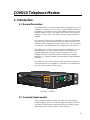
1. COM210 .................................................................................................... 1
2. CR1000 and COM210 Using Remote Telephone Line ............................. 4
3. CR10X with CR10 Wiring Panel and COM210 Using
RJ11C Telephone Jack............................................................................ 5
A-1. LoggerNet Screen .............................................................................. A-2
A-2. COM210 to Computer Connection.................................................... A-3
B-1. CS I/O Pin Out ................................................................................... B-1
List of Tables
1. Dataloggers that Require Direct 12 VDC Connection to COM210........... 3
ii
COM210 Telephone Modem
1. Introduction
1.1 General Description
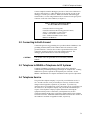
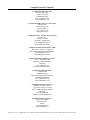
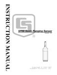
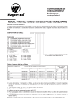
The COM210 Modem is a 9600 baud phone modem employing the Hayes AT
command set. Its primary use is as a remote site phone modem connected to a
CSI datalogger. The modem is powered and enabled by the battery-powered
datalogger. When not active, the COM210 draws less than 120 µA from the
datalogger’s 12 VDC output. The COM210 is a drop in replacement for the
COM200.
The COM210 is connected to a CSI datalogger by using a 9-pin subminiature
D connector cable. This is the same 9-pin CS I/O connection common to all
Campbell Scientific dataloggers (except the CR200 series). This is not an RS232 connection. Appendix B describes the configuration of this connector.
The COM210 can be used as an originate modem at the datalogger site. For
Edlog dataloggers (e.g., CR510, CR10X, CR23X), use Instruction 97 to
program the datalogger to originate a call to the computer; refer to your
datalogger manual for a detailed description of Instruction 97. CRBasic
dataloggers (e.g., CR1000, CR3000) use the Dial Sequence and Dial Modem
instructions.
The COM210 features a built-in speaker to allow monitoring of calling and
connection operations. See Appendix A.3 for the Hayes AT commands that
affect the speaker on/off and volume settings.
CAMPBELL
SCIENTIFIC
INC.
COM210 MO
DE
M
Complies
with Part 68
, FCC rules
Ringer Eq
uivalence
. FCC Re
gistration No
0.9B.Requ
ired Conn
This equip
ector USOC . B9QUSA-31402-M
M-T
computin ment complies wi
RJ11C. Ca
g
nadian Lo
th
unaccept device. Operation the requirements
ad No. 5
ab
whatever le interference of this equipmen in Part 15 of FCC
t in a resid
Rules for
to radio
steps ar
and TV
Clas
ential area
e necess
rece
ary to co
S/N
may caus s A
rrect the ption requiring th
e
e operat
interfere
or to take
nce.
G 12V
GND
IN USA
TIP
MADE
RING
1002
FIGURE 1. COM210
1.2 Computer Requirements
A Hayes-compatible modem is used at the computer site with Campbell
Scientific computer software to call the datalogger attached to the COM210.
The computer’s modem must be configured to the proper settings using the
modem initialization strings listed in the software programs.
1
COM210 Telephone Modem
2. Specifications
•
Bell 212A, CCITT V.22, and CCITT V.32 compatible
•
Full duplex at 9600 (default setting) and 1200 baud to datalogger
•
V.42 LAPM and MNP2-4 error correction
•
Hayes AT command set
•
On-board speaker
•
RJ-11C telephone jack
•
FCC and IC (formerly known as DOC) approval
•
Pulse or tone dialing
•
Current drain: 120 µA quiescent, 160 mA active
•
Direct connection to and powered by CSI dataloggers
•
Supply requirements: 12 VDC regulated power supply
•
Internally switches 12 VDC external power minimizing current drain
•
Logic levels: below 1.5 V inputs a low state and above 3.5 V inputs a
high state. A low voltage level on the TX data input (pin 9) and RX data
output (pin 4) represents a mark
•
Operational temperature: -25oC to +50oC standard (Extended operational
temperature range of -55°C to +85°C is available at time of purchase.)
•
Size: 5.2” x 1.7” x 3.6” // 13.1 x 4.3 x 9.2 cm
•
Weight: 0.75 lbs // 0.34 kg
3. Installation
The COM210 is designed to be used with standard analog telephone lines. It
will not work with a digital telephone line. Connection to telephone-companyprovided coin service (central office implemented systems) is prohibited.
Connection to party line service is subject to state tariffs.
3.1 Connecting to Datalogger
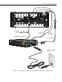
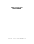
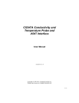
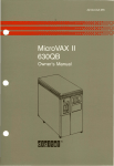
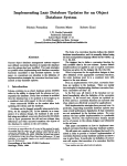
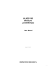
Connect the cable from the telephone RJ11C jack to the modem as shown in
Figure 3. If the telephone company has not installed surge protection in the
telephone line (no RJ11C jack), one must install surge protection (CSI item
number 6362 or 4330) and connect the ring and tip terminal blocks as shown
in Figure 2.
2
COM210 Telephone Modem
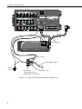
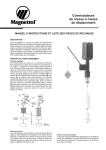
Current Campbell Scientific dataloggers provide 12 VDC to the COM210 via
the SC12 cable (Figure 2). Older dataloggers do not provide 12 VDC on the
datalogger's CS I/O 9 pin connector. When used with the older dataloggers
listed in Table1, 12 VDC and ground need to be connected via the green power
connector on the side of the COM210 (see Figure 3).
Table 1. Dataloggers that Require Direct
12 VDC Connection to COM210
CR10(X) with silver wiring panel
CR10(X) with black CR10 wiring panel (P/N 8032)
21X(L)—serial number 13,442 or lower
CR500⎯serial number 1764 or lower
CR7—700X serial number 2778 or lower
BDR301 and BDR320
3.2 Connecting to Earth Ground
Connect the green 14 awg grounding wire (provided with the COM210) to the
grounding terminal (GND) on the COM210 and to the enclosure’s earth
ground connection. If the site does not have a grounded enclosure, then
connect the ground wire directly to an earth ground connection. The
datalogger ground should also be tied to the earth ground.
CAUTION
The modem must be grounded for its transient protection
to work.
3.3 Telephone to MD485 or Telephone to RF Systems
Telephone to MD485 or telephone to radio systems can be utilized for
communicating with multiple dataloggers through one telephone line. Nothing
additional or special is required for the telephone part of the link. See the
MD485 or RF Manuals for complete information on their special requirements.
3.4 Telephone Service
The goal of the telephone company is to provide you with the best service it
can. In order to do this, it may occasionally be necessary for them to make
changes in their equipment, operations, or procedures. If you have any
questions about your telephone line, such as how many pieces of equipment you
can connect to it, the telephone company will provide this information upon
request. If the telephone company requests information concerning the
equipment which you have connected to your telephone line, the FCC
registration number and the ringer equivalence number (REN) of the COM210
are listed on its label. Additional technical information from the FCC and IC on
the COM210 is available in Appendix D and E, respectively.
3
COM210 Telephone Modem
3
L
H
4
5
L
H
2
6
7
L
H
3
POWER IN
G 12V
8
4
L
P2
2
1
P1
1
H
EX1
SE
DIFF
CAUTION
DC ONLY
G 12V
GROUND
LUG
11 12
6
H L
10
5
H
L
13 14
7
H L
CR1000
15 16
8
H L
WIRING PANEL
EX3
9
EX2
SE
DIFF
CS I/O
PERIPHERAL PORT
G
C8
C7
C6
C5
G
C4
COM3 COM4
Tx Rx Tx Rx
C3
COM1 COM2
Tx Rx Tx Rx
C2
G
12V
SW-12
G
12V
G
G
5V
POWER OUT
C1
RS-232 (Not Isolated)
SN:
MADE IN USA
SDM
COM210 MODEM
S/N
0002
GND
This equipment complies with the requirements in Part 15 of FCC Rules for Class A
computing device. Operation of this equipment in a residential area may cause
unacceptable interference to radio and TV reception requiring the operator to take
whatever steps are necessary to correct the interference.
SC12 Cable
TIP
Complies with Part 68, FCC rules. FCC Registration No. B9QUSA-75378-MM-T
Ringer Equivalence 0.9B. Required Connector USOC RJ11C.
RING
CAMPBELL
SCIENTIFIC
INC.
MADE IN USA
Blue = Ring
Burial Phone Cable
Earth
Ground
Blue/White = Tip
Phone Line
Transient Protector
(Model 6362 or 2372-01)
FIGURE 2. CR1000 and COM210 Using Remote Telephone Line
4
COM210 Telephone Modem
DIFF
SE
AG H L AG H L AG H L AG E3 AG G G
4
5
6
7 8
9 10
11 12
G G G G
CAMPBELL
SCIENTIFIC
INC.
SE
DIFF
G 12V
POWER
IN
SERIAL I/O
CR10
MADE IN USA
WIRING PANEL NO.
SWITCHED
12V
1 2
3 4
5 6
CONTROL
EARTH
1
2
3
AG H L AG H L AG H L AG E1 E2 G G
G 5V 5V P1 P2
C8 C7 C6 C5 C4 C3 C2 C1
To Earth
Ground
Red
(+12v)
14 AWG Ground Wire
CAMPBELL
SCIENTIFIC
INC
12V 12V
SWITCHED
12V
Black
(Ground)
SC12 Cable
COM210 MO
DE
.
M
Complies
with
Ringer Equ Part 68, FCC rules.
ivalence 0.9
FCC Registra
B.Required
tion No. B9Q
This equipm
Connector
USA-31402
USOC RJ1
ent complie
-MM-T
computing
1C.
s with
Canadian
Load No.
unaccepta device. Operation the requirements
5
whatever ble interference of this equipment in Part 15 of FCC
Rules for
to radio
in a reside
steps are
and TV
Class A
ntial area
necessar
S/N
may cau
y to correc reception req
se
uiring the
t the inte
operator
rference.
to take
G 12V
GND
IN USA
TIP
MADE
RING
1002
Telephone Wall
Jack
FIGURE 3. CR10X with CR10 Wiring Panel and COM210 Using RJ11C Telephone Jack
5
COM210 Telephone Modem
4. Troubleshooting
When the Campbell Scientific software cannot establish a link to the remote
datalogger that is connected to the COM210, check the following:
1)
Verify the modem initialization settings have been changed for the
specific calling modem on the computer. See software manual and/or
help screens for more information.
2)
Verify nothing else is using the same COM port on the computer. Even if
a program is minimized in windows, it may have a lock on the COM port.
Some notebook computers do not automatically activate the COM ports.
Verify the COM port you are using is activated.
3)
The Campbell Scientific software will display an activity of
communication as the link is being established. Assuming the above
items are O.K., the software should display in the activity window/screen
something such as “ATDT#######”. Where the #### is the telephone
number listed in the dialing path of the software for the datalogger you
are trying to call.
The local modem attached to the computer will respond back to the
computer with result codes showing how the call is progressing. These
result codes can be either numeric (0, 1, 2, etc.) or "verbose" ("OK",
"CONNECT", "RING", etc.). Prior to PC208W 3.0, our software
expected numeric result codes. PC208W 3.x and LoggerNet uses
"verbose" result codes to determine call progress. The V command is
used to select between numeric or verbose result codes. Depending on
the version of PC208W being used, the initialization string for the modem
may need to be changed for the appropriate form of result codes. The
result code returned may indicate why the call is unsuccessful. Appendix
A has a list of possible result codes.
6
4)
Can you attach a normal analog telephone to the line and make a call out?
If not, contact your local telephone company. If you can make a call out
but the connection is poor or faint, contact your local telephone company.
5)
Verify the COM210 is receiving 12 VDC. If the COM210 is receiving 12
VDC from a separate power supply instead of the datalogger, is the
ground of the separate power supply connected to the datalogger’s
ground?
6)
Verify the COM210 is the only Modem Enable device connected to the
datalogger. Other common Campbell Scientific modem enable devices
are the SC32B, some RF modems, and the MD485.
7)
Verify the datalogger is turned on.
COM210 Telephone Modem
To comply with FCC rules and regulations, all repairs on the COM210 modem
must be performed by Campbell Scientific, Inc. or an authorized agent of
Campbell Scientific, Inc. For assistance in installation, troubleshooting, or for
repair, contact Campbell Scientific:
Campbell Scientific, Inc.
815 West 1800 North
Logan, Utah 84321-1784
Telephone: (435) 753-2342
Fax: (435) 750-9540
Web site: www.campbellsci.com
5. Modem Settings in Non-Volatile Memory
The COM210 comes from the factory with the appropriate settings for most
applications. It is programmed to answer the call as soon as it detects the call.
One may modify the COM210’s settings in non-volatile memory using Hayes
AT commands. Appendix A describes the procedures and commands required
to make the changes described in this section.
Some of the settings one may change are:
Disable auto-answer: This option is used only when the modem is not to
answer a call. For example, the COM210 is connected to a telephone line that
is to be used part time for voice communication. In this situation it is best to
have the datalogger call the computer.
Speaker On/Off and Volume: Default settings have the speaker on during
call establishment only and set to a low volume. To conserve on current drain
during the connection time or so one doesn’t hear the speaker, one may turn
the speaker completely off. When one wants to hear the speaker better than
the default low volume setting, one may change it to a higher volume level.
Answer on Xth ring: This option is used when the modem is sharing a line
and you only want it to answer after a specified number of rings. For example,
the COM210 is sharing a line with people at an office. It can be programmed
to only answer after the third ring. If the PC calls when the office is closed and
no one answers the phone after three rings, the datalogger will pick it up.
Change telephone system types: Change from the Bell 212A (U.S. and
Canada) system to a CCITT V.32 (foreign, 9600 baud) or CCITT V.22
(foreign, 1200 baud) system. This does not mean that the COM210 is tested
and approved for all foreign countries.
CCITT is an international consultative committee that sets international
communications usage standards. V.32 and V.22 are standards that the
COM210 meets.
This is a blank page.
7
COM210 Telephone Modem
8
Appendix A. Modifying the Non-Volatile
Memory
To modify the COM210’s settings, one must communicate directly to the
COM210. This may be accomplished by using one of the two methods below.
CAUTION
Changing any of the modem's settings may result in
communication problems. After changing the settings,
try the modem locally before installing it at a remote
location. To speed problem resolution when contacting
Campbell Scientific for support, please inform us of any
modem setting changes that have been made.
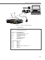
A.1 Hardware Connection to COM210
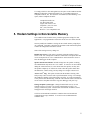
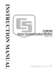
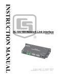
Connect the COM210 to a computer using an SC532A interface (Figure A-2).
The computer software (LoggerNet) used to communicate with the COM210
must raise the RS-232 DTR and set RTS low.
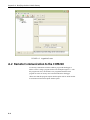
The following example shows how to change the COM210 to answer on the
3rd ring.
First attach a series of Generic devices ending with a datalogger to a COM
port. On the first Generic device check Raise DTR and select “The RTS line
will be lowered” (see Figure A-1). Now send the following commands to the
COM210 through the LoggerNet terminal emulator (select device Generic_2
and 9600 baud in the terminal emulator).
ATS0=3
AT&W0
A-1
Appendix A. Modifying the Non-Volatile Memory
FIGURE A-1. LoggerNet Screen
A.2 Remote Communication to the COM210
To remotely communicate with the COM210, program the datalogger to
initiate a call to it using a program similar to the Example Program 1.* After
this program runs once, the modem is now programmed and the actual
program one wants to run may now be downloaded to the datalogger.
*Please note that this program requires that the option code for an RF modem
be used instead of the normal phone modem option.
A-2
Appendix A. Modifying the Non-Volatile Memory
9227
PERIPHERAL
PC
Logan, Utah
SC532A
RS232 to CS I/O
MADE IN USA
SN:
POWER
To 12V
To GND
Red
Black
CAMPBELL
SCIENTIFIC
INC
SC12 Cable
COM210 MO
DE
.
M
Complies
with
Ringer Equ Part 68, FCC rules
. FCC Reg
ivalence 0.9B
istration No.
.Required
B9QUSA-314
This equipme
Connector
USOC RJ1
02-MM-T
nt complies
computing
1C. Canadia
with
dev
n Load No.
unacceptab ice. Operatio the requirements
5
n
whateve le interference of this equipment in Part 15 of FCC
r steps are
Rules for
to radi
in a residen
Class A
necessary o and TV rece
tial area
S/N
may cau
ption
to correct
se
the interfer requiring the ope
rator to take
ence.
G 12V
TIP
RING
MADE
IN USA
GND
1002
FIGURE A-2. COM210 to Computer Connection
Example Program 1
*Table 1 Program
01: 1
Execution Interval (seconds)
1: Initiate Telecommunications (P97)
1: 02
RF Modem/9600 Baud
2: 1
Disabled when User Flag 1 is High
3: 20
Seconds Call Time Limit
4: 0
Seconds Before Fast Retry
5: 0
Fast Retries
6: 0
Minutes before Slow Retry
7: 1
Failures Loc [ Failure ]
8: 0
Data Logger ID
2: Extended Parameters (P63)
1: 65
Option ;A
2: 84
Option ;T
3: 83
Option ;S
4: 48
Option ;0
5: 61
Option ;=
6: 50
Option ;2 results in 3 rings (rings = n + 1)
7: 38
Option ;&
8: 87
Option ;W
A-3
Appendix A. Modifying the Non-Volatile Memory
3: Extended Parameters (P63)
1: 48
Option ;0
2: 68
Option ;D
3: 84
Option ;T
4: 13
Option
5: 00
Option
6: 00
Option
7: 00
Option
8: 00
Option
After sending above program, disconnect from datalogger and wait 30 seconds,
allowing program to finish, before connecting again.
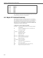
A.3 Hayes AT Command Summary
This manual does not attempt to be a primer on the Hayes AT command set.
The commands are, therefore, only summarized below. For most applications,
these commands will not need to be used. Except as noted, all commands
should begin with an “AT” and end with a carriage return (hit the [Enter] key).
There are no “O” as in Oscar commands, only “0” as in Zero commands. All
commands must be issued as CAPITAL letters.
COMMANDS TO CHANGE DEFAULT MODES:
B1 (default)
B0
A-4
CCITT V.32 (9600 baud), Bell 212A (1200 baud), and Bell
103 (300 baud)
CCITT V.32 (9600 baud), CCITT V.22 (1200 baud), and
CCITT V.21 (300 baud)
L0
L1 (default)
L2
L3
Lowest speaker volume
Low speaker volume
Medium speaker volume
High speaker volume
M0
M1 (default)
M2
Speaker always off
Speaker on during call establishment
Speak on during entire call session
S0=0
S0=1 (default)
S0=2
S0=n
Disable Auto Answer
Answer on second ring
Answer on third ring
Answer on (n + 1) ring. (maximum n is 2)
&F
&W0
&V
Restore factory defaults
Store current profile as Profile to load on power up
Display the current profile to the screen
Appendix A. Modifying the Non-Volatile Memory
RESULT CODES:
0
1
2
3
4
5
6
7
8
12
13
17
CAUTION
OK
Connect
Ring
No Carrier
Error
Connect 1200 Baud
No Dial Tone
Busy
No Answer
Connect 9600 Baud
Connect 9600/14400 Baud
Connect 9600 Baud
If more than three rings are specified (first P63 parameter
6 > 50), the datalogger may time out before the modem
answers; communication will never be established! It is
possible in some conditions to allow more than three rings.
Consult a Campbell Scientific applications engineer about
optimizing modem negotiations before trying this and be
sure to try the set up locally before installing at a remote
location.
A-5
Appendix A. Modifying the Non-Volatile Memory
This is a blank page.
A-6
Appendix B. CS I/O Connection
B.1 CS I/O 9-Pin Connection
The pin out of the connector is shown in Figure B-1. The direction of the
signal relative to the modem is shown in parenthesis. Unless specified
otherwise, all levels are 0 V for logic low, 5 V for logic high.
FIGURE B-1. CS I/O Pin Out
1.
(input) +5 VDC supply. Not used by COM210.
2.
(input) Ground
3.
(output) Ring - a logic high signifies a ring signal has been detected
4.
(output) RX Data - serial data from COM210
5.
(input) Modem Enable - a logic high internally switches power to the
modem. A logic low internally shuts off power to the modem.
6.
(input) Serial Device Enable - a logic high disables communication with
the modem without removing power or changing the modem's mode.
7.
(input) SDC clock. Not used by COM210.
8.
(input) +12 VDC supply
9.
(input) TX Data - serial data to COM210
B-1
This is a blank page.
Appendix C. Theory of Operation
C.1 Theory of Operation
The COM210 modem is used to transmit data over bandwidth-limited channels
such as telephone lines by modulating audio tones. The COM210 uses various
modulation schemes including FSK (Frequency Shift Keying), TCM (Trellis
Coded Modulation), QAM (Quadrature Amplitude Modulation), and DPSK
(Differential Phase Shift Keying).
The telephone company gives a 40 to 150 VRMS, 20 Hz signal on the
telephone lines to signify a ring, which is typically on for two seconds and off
for four seconds. The COM210 is supplied with 12 V from the datalogger’s
CS I/O connector or from the COM210’s external power connector. The 12 V
is then regulated to +5 V to give power to the ring detect circuitry. The ring
detection circuitry is continuously powered but draws less than 2 µA. The ring
signal is passed on to the datalogger through an opto-coupler. The datalogger
responds to a “ring” by raising the Modem Enable line, which internally
switches the regulated +5 V supply to the rest of the modem’s circuitry.
The modem then answers and remains off-hook until it loses the carrier or the
datalogger lowers the Modem Enable line. The datalogger lowers the Modem
Enable line by remote command or after 40 seconds in the absence of a
command. When the Modem Enable line goes low, the COM210 internally
removes the +5 V from the modem circuitry, dropping power to the off-hook
relay and thus placing the telephone line on-hook. The COM210’s ring
circuitry is still powered at this time.
To reject noise common to both telephone lines and to satisfy registration
requirements, the modem circuitry is electrically isolated from the telephone
lines by using an opto-isolator and a coupling transformer.
C-1
This is a blank page.
Appendix D. FCC Warning to Users of
Class A Computing Devices
WARNING
This equipment generates, uses, and can radiate radio
frequency energy, and if not installed and used in
accordance with the instruction manual, may cause
interference to radio communications. It has been
tested and found to comply with the limits for a Class
A computing device pursuant to Subpart J of Part 15
of FCC Rules, which are designed to provide
reasonable protection against such interference when
operated in a COMMERCIAL ENVIRONMENT.
Operation of this equipment in a residential area may
cause interference to radio and television reception.
The operator must take whatever measures are
necessary to correct the interference.
D-1
This is a blank page.
Appendix E. IC Information
NOTE
Industry Canada (IC) was formerly known as DOC.
CP-01, Issue 8, Part I
Section 14.1
“NOTICE: The Industry Canada label identifies certified equipment. This
certification means that the equipment meets certain telecommunications
network protective, operational and safety requirements as prescribed in the
appropriate Terminal Equipment Technical Requirements document(s). The
Department does not guarantee the equipment will operate to the user’s
satisfaction.
“Before installing this equipment, users should ensure that it is permissible to
be connected to the facilities of the local telecommunications company. The
equipment must also be installed using an acceptable method of connection.
The customer should be aware that compliance with the above conditions may
not prevent degradation of service in some situations.
“Repairs to certified equipment should be coordinated by a representative
designated by the supplier. Any repairs or alterations made by the user to this
equipment, or equipment malfunctions, may give the telecommunications
company cause to request the user to disconnect the equipment.
“Users should ensure for their own protection that the electrical ground
connections of the power utility, telephone lines and internal metallic water
pipe system, if present, are connected together. This precaution may be
particularly important in rural areas.
CAUTION
Users should not attempt to make such connections
themselves, but should contact the appropriate electric
inspection authority, or electrician, as appropriate.”
CP-01, Issue 8, Part I
Section 14.2
“NOTICE: The Ringer Equivalence Number (REN) assigned to each terminal
device provides an indication of the maximum number of terminals allowed to
be connected to a telephone interface. The termination on an interface may
consist of any combination of devices subject only to the requirement that the
sum of the Ringer Equivalence Numbers of all the devices does not exceed 5.”
E-1
This is a blank page.
This is a blank page.
Campbell Scientific Companies
Campbell Scientific, Inc. (CSI)
815 West 1800 North
Logan, Utah 84321
UNITED STATES
www.campbellsci.com
[email protected]
Campbell Scientific Africa Pty. Ltd. (CSAf)
PO Box 2450
Somerset West 7129
SOUTH AFRICA
www.csafrica.co.za
[email protected]
Campbell Scientific Australia Pty. Ltd. (CSA)
PO Box 444
Thuringowa Central
QLD 4812 AUSTRALIA
www.campbellsci.com.au
[email protected]
Campbell Scientific do Brazil Ltda. (CSB)
Rua Luisa Crapsi Orsi, 15 Butantã
CEP: 005543-000 São Paulo SP BRAZIL
www.campbellsci.com.br
[email protected]
Campbell Scientific Canada Corp. (CSC)
11564 - 149th Street NW
Edmonton, Alberta T5M 1W7
CANADA
www.campbellsci.ca
[email protected]
Campbell Scientific Ltd. (CSL)
Campbell Park
80 Hathern Road
Shepshed, Loughborough LE12 9GX
UNITED KINGDOM
www.campbellsci.co.uk
[email protected]
Campbell Scientific Ltd. (France)
Miniparc du Verger - Bat. H
1, rue de Terre Neuve - Les Ulis
91967 COURTABOEUF CEDEX
FRANCE
www.campbellsci.fr
[email protected]
Campbell Scientific Spain, S. L.
Psg. Font 14, local 8
08013 Barcelona
SPAIN
www.campbellsci.es
[email protected]
Please visit www.campbellsci.com to obtain contact information for your local US or International representative.