1
Intelligent Technologies
QCPort System Install Manual
November 2005
Supercedes November 2004
MN05001002E (C)
For more information visit www.eatonelectrical.com
Intelligent Technologies QCPort System Install Manual
November 2005
Important Notice – Please Read
The product discussed in this literature is subject to terms and conditions outlined in
appropriate Cutler-Hammer selling policies. The sole source governing the rights and
remedies of any purchaser of this equipment is the relevant Cutler-Hammer selling policy.
NO WARRANTIES, EXPRESS OR IMPLIED, INCLUDING WARRANTIES OF FITNESS
FOR A PARTICULAR PURPOSE OR MERCHANTABILITY, OR WARRANTIES
ARISING FROM COURSE OF DEALING OR USAGE OF TRADE, ARE MADE
REGARDING THE INFORMATION, RECOMMENDATIONS AND DESCRIPTIONS
CONTAINED HEREIN. In no event will Cutler-Hammer be responsible to the
purchaser or user in contract, in tort (including negligence), strict liability or
otherwise for any special, indirect, incidental or consequential damage or loss
whatsoever, including but not limited to damage or loss of use of equipment, plant
or power system, cost of capital, loss of power, additional expenses in the use of
existing power facilities, or claims against the purchaser or user by its customers
resulting from the use of the information, recommendations and descriptions
contained herein.
Important User Information
Due to the variety of uses for the products described in this publication, those responsible
for the application and use of this control equipment must satisfy themselves that all
necessary steps have been taken to assure that each application and use meets all
performance and safety requirements, including any applicable laws, regulations, codes,
and standards.
Only qualified persons, as defined in the National Electric Code, who are familiar with the
installation, maintenance, and operation of these products and the equipment onto which
they are to be installed, as well as applicable local, state, and national regulations and
industry standards and accepted practices regarding safety of personnel and the
equipment safety, should be permitted to install, maintain, or operate this system. These
instructions are provided only as a general guide to such qualified persons and are not
all-inclusive. They do not cover every application or circumstance that may arise in the
installation, maintenance, or operation of this equipment. Users are advised to comply
with all local, state, and national regulations and industry standards and accepted
practices regarding safety of personnel and equipment safety.
The illustrations, charts, sample programs and layout examples shown in this guide are
intended solely for example. Since there are many variables and requirements
associated with any particular installation, Cutler-Hammer does not assume responsibility
or liability (including intellectual property liability) for actual use based upon the examples
shown in this publication.
Reproduction of the contents of this copyrighted publication, in whole or in part, without
written permission of Cutler-Hammer is prohibited.
MN05001002E
For more information visit www.eatonelectrical.com
Page 2
Intelligent Technologies QCPort System Install Manual
November 2005
Throughout this manual, various types of notices are provided to alert you to possible
injury to people or damage to equipment under specific circumstances. These will help
you:
•
Identify a hazard
•
Avoid the hazard
•
Recognize the consequences
These include “Attention” and “Important” notices; please note the following examples.
Warning
Identifies information about practices or circumstances that can lead to personal
injury or death, property damage or economic loss.
Warning
Identifies information that is especially important for successful application and
understanding of the product.
National Electric Code
Warning
Do not install or perform maintenance on the QCPort system while the system is
energized. Death or severe personal injury, as well as damage to other equipment,
can result from contact with energized equipment. Verify that no voltage is present
before proceeding with installation or maintenance.
Much of the information provided in this manual is representative of the capability of a
QCPort system and its associated components. The National Electric Code (NEC), in the
United States, and the Canadian Electric Code (CE Code), in Canada, places limitations
on configurations and the maximum allowable power/current that can be provided.
The instructions and examples in this manual are based on Class 2 power supplies.
Warning
Be sure that all national and local codes are thoroughly researched and adhered to
during the planning and installation of your QCPort system.
MN05001002E
For more information visit www.eatonelectrical.com
Page 3
Intelligent Technologies QCPort System Install Manual
November 2005
Table of Contents
INTERCONNECTIVITY USING QCPORT....................................................................................... 6
INTRODUCING QCPORT .................................................................................................................. 6
QCPORT PHYSICAL CHARACTERISTICS ........................................................................................... 6
EXAMPLES OF QCPORT USE ........................................................................................................... 7
One Device Using QCPort
7
Multiple Peripherals on One Device Using QCPort
8
Multiple Devices Being Controlled And Monitored Remotely Using QCPort
9
QCPORT OPERATING MODES ................................................................................................... 10
Overview
10
Understanding Master-Slave
10
Understanding Peer
10
OVERVIEW OF QCPORT INTERCONNECT SYSTEM................................................................ 11
DEVICE CONNECTION IN A QCPORT SYSTEM ................................................................................. 11
QCPort Backplane
11
QCPort Interconnect Cable
12
DAISY CHAIN ................................................................................................................................ 14
TRUNK DROP ................................................................................................................................ 14
PHYSICAL PLACEMENT .................................................................................................................. 15
USING BIASING RESISTORS ........................................................................................................... 16
APPLICATION EXAMPLE ................................................................................................................. 17
PLANNING A QCPORT INTERCONNECT SYSTEM................................................................... 18
GUIDELINES FOR SUPPLYING POWER............................................................................................. 18
IT. Power Supplies
18
Other Power Supplies
18
POWER RATINGS .......................................................................................................................... 18
QCPort Interconnect Cable Rating
18
LOCATING A POWER SUPPLY ......................................................................................................... 19
1 Power Supply
20
GROUNDING THE INTERCONNECT SYSTEM ..................................................................................... 20
SIZING A POWER SUPPLY ......................................................................................................... 21
SUPPLYING POWER ...................................................................................................................... 21
ADJUSTING THE CONFIGURATION................................................................................................... 21
SIZING CALCULATION .................................................................................................................... 22
USING THE SIZING CALCULATION ................................................................................................... 23
Example 1 End Connected Power Supply
23
Example 2 End Connected Power Supply
23
Example 3 Middle Connected Power Supply
24
TROUBLESHOOTING AND MAINTENANCE .............................................................................. 25
APPENDIX A: USING LONG RUN CABLES ............................................................................... 26
TECHNICAL SUPPORT ................................................................................................................ 28
MN05001002E
For more information visit www.eatonelectrical.com
Page 4
Intelligent Technologies QCPort System Install Manual
November 2005
Table of Figures
Figure 1: Example of One Device Using QCPort
Figure 2: Example of Multiple Peripherals on One Device Using QCPort
Figure 3: Example of Remote Connection Using QCPort
Figure 4: QCPort Backplane Connector
Figure 5: 6 Pin QCPort Linear Connector
Figure 6: QCPort Interconnect Cable
Figure 7: QCPort Powered Interconnect Cable Wiring
Figure 8: Long Run Cable Connection
Figure 9: Daisy Chain Topology
Figure 10: QCPort Biasing Resistor Options
Figure 11: Distributed Motor Control Panel
Figure 12: 1 Power Supply
Figure 13: Example of Long Run Cable: One Power Supply (End-Connected)
7
8
9
11
11
12
12
13
14
16
17
20
26
MN05001002E
Page 5
For more information visit www.eatonelectrical.com
Intelligent Technologies QCPort System Install Manual
November 2005
Interconnectivity Using QCPort
Introducing QCPort
The interface demands on control devices continues to increase at a rapid pace. An
intelligent control device requires connection to configuration and monitoring tools,
operator interfaces, and other peripheral devices, as well as the option to connect to a
variety of industrial fieldbusses. At the same time, the intelligent devices continue to
shrink in size and cost, forcing distribution of the field connections that once were native
on the devices.
QCPort is a flexible interface port that integrates the many connectivity needs of the
intelligent device into a single device port for the means of control, setup, and
configuration. The integration of these capabilities provides interface options that are
powerful and cost effective. In addition to the interface functionality of QCPort, care has
been taken to insure that systems that connect via QCPort are simple to configure,
connect, and maintain.
QCPort Physical Characteristics
In an effort to use existing proven technology, QCPort uses the RS485 physical layer.
This physical layer is common to many industrial communication interfaces and has a
long and proven track record within industrial applications. QCPort is a four-wire system
where there is an A and B for signal and a +DC and Ground for device power.
Depending on the type of device interconnect and the distance between devices, there
are many choices for the type of interconnect physical media; these choices will be
discussed further in the manual.
MN05001002E
For more information visit www.eatonelectrical.com
Page 6
Intelligent Technologies QCPort System Install Manual
November 2005
Examples of QCPort Use
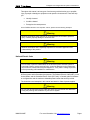
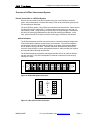
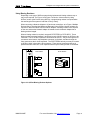
One Device Using QCPort
In many applications, the QCPort will be used as the connection between a motor
controller and the user interface/configuration keypad. The following figure contains a
one-to-one solution, where the user interface is powered from the motor controller’s
QCPort. A separate power supply is not required for the user interface. In this example,
the user interface is connected to Channel 0 of the motor controller. Channel 0 is
specifically used for connection to the user interface and operator stations.
Figure 1: Example of One Device Using QCPort
The interconnect supplied with the operator interface connects the operator interface to
the motor controller. This connection provides for 24V DC and communication; the
operator interface is powered from the motor controller. Configuration of the operator
interface or the motor controller for this application is not required for communication to
be established. The user can then use the operator interface to configure the motor
controller parameters, operate the motor controller, and monitor the operation of the
motor controller.
The information contained within this manual does not include instructions for setup or
operation of the motor controller or operator interface. For instructions on how to apply
the operator interface, refer to the manual for that device.
MN05001002E
For more information visit www.eatonelectrical.com
Page 7
Intelligent Technologies QCPort System Install Manual
November 2005
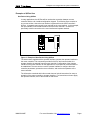
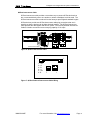
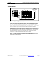
Multiple Peripherals on One Device Using QCPort
QCPort has been designed to support multiple devices connected to one motor
controller, without the motor controller having prior knowledge of the connected device.
Devices that can be connected to a motor controller include user interface products and
IO products. Once again, the devices are connected to Channel 0 of the motor controller.
The figure below illustrates an application example that includes a user interface and IO
modules. The input module is used to apply a hard-wired HOA while the output module
is used to annunciate the motor controller status and trip conditions. The mapping of the
data between the motor controller and the IO devices does not require a tool and is
seamless to the user.
Figure 2: Example of Multiple Peripherals on One Device Using QCPort
When multiple devices are connected to one motor controller, the user has to be aware of
the power demand of all of the peripherals. Verify the power requirement of this system
by adding up the power demands of the peripherals to see if they exceed the power
capacity of the motor controller. If the power capacity of the motor controller is exceeded,
a power supply is required for QCPort. To help size the power supply, consult “Locating
a Power Supply” later in the manual.
MN05001002E
For more information visit www.eatonelectrical.com
Page 8
Intelligent Technologies QCPort System Install Manual
November 2005
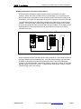
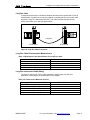
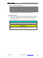
Multiple Devices Being Controlled And Monitored Remotely Using QCPort
When an industrial fieldbus adapter is used within a system, the adapter will act as a
subscanner presenting the QCPort devices as IO to the industrial fieldbus. This allows
the QCPort devices to be monitored, controlled, and configured from a remote location.
For this type of application, a power supply will be required; it can be the same power
supply that is used for the motor controllers.
DeviceNet
IT. EM Starters and D77B-QSNAPs
IT. 24V DC
Power Supply
Figure 3: Example of Remote Connection Using QCPort
Since a power supply sizing is required, refer to “Locating a Power Supply” later in this
manual. Along with the power supply sizing, physical media restrictions must be
followed. This includes the length of the interconnects, type of interconnects, and the
power capabilities for the interconnects.
This type of application requires some configuration. The Group IDs for the QCPort
devices need to be set to unique IDs, the adapter requires an address configuration, and
then the mapping feature needs to be invoked to map the QCPort data to the industrial
fieldbus. None of these configuration requirements require a software tool. If advanced
configuration of the QCPort devices is required, then a software tool or a QCPort user
interface will be required. For information on configuration of the QCPort devices, refer to
the user manual for those devices.
MN05001002E
For more information visit www.eatonelectrical.com
Page 9
Intelligent Technologies QCPort System Install Manual
November 2005
QCPort Operating Modes
Overview
The QCPort system is capable of two operating modes:
•
Master-Slave
•
Peer
When the system is intended to be used in a master-slave setting there is no
configuration necessary other then setting the address (group ID) of each device to a
unique address
Peer devices require a configuration setting for normal operation. Devices that will
communicate peer are the S811 soft start and the user display (DIM).
Understanding Master-Slave
Master-Slave is when a single device (master) is responsible for scheduling all
communication to the remainder of the devices (slaves). In most cases, this will be
limited to IO applications where a Network Adapter is controlling the IO and motor control
devices. A slave only communicates when it is communicated to; thus eliminating
collisions. Since there are no unscheduled communications in a Master-Slave system,
the scan time of a QCPort system will be deterministic.
An example of a Master-Slave system can be found in Figure 3: Example of Remote
Connection Using QCPort.
Understanding Peer
Peer communication is when devices broadcast their messages on event transitions or a
time base to a specific device or groups of devices. Unlike Master-Slave, this mode has
no master scheduler in the system, and all devices produce data on an internal schedule
or when an event occurs (e.g., input transition, fault). In this mode, there is collision
detection to detect if a message is damaged by two devices talking at the same time. If
this occurs, then the devices both stand off (at different stand off times) for a period of
time and attempt to re-transmit the message.
An example of a Peer-to-Peer system can be found in Figure 2: Example of Multiple
Peripherals on One Device Using QCPort.
MN05001002E
For more information visit www.eatonelectrical.com
Page 10
Intelligent Technologies QCPort System Install Manual
November 2005
Overview of QCPort Interconnect System
Device Connection in a QCPort System
Devices are connected into a QCPort system using one of the following connection
types—either a backplane or interconnect cabling. Both of the connection types provide
for communication and power.
The entire QCPort system, using QCPort pre-manufactured interconnects, cannot exceed
100 feet [30 meters] in total length. For systems that require longer runs, the long run
interconnect is used. Using the long run interconnect, the system length is increased to
500 feet [150 meters] @ 460Kbaud and 1000 feet [300 meters] @ 230Kbaud. In this
case, special care has to be taken to size the power supply correctly for the distance.
QCPort Backplane
The QCPort backplane provides a convenient way to connect the Network Adapter and
IO devices that are located in close proximity to one another. The QCPort backplane
mounts within a DIN rail, allowing the receptacles on the back of the Network Adapter
and IO products to plug into them. This auto connection eliminates the need for any
customer communication or power wiring between devices, while providing hot insertion
and removal without affecting other devices.
The QCPort backplane provides the data signals and the 24V DC to power all devices
that are connected. The QCPort backplane is limited to a maximum current carrying
capacity of 6 amps.
Figure 4: QCPort Backplane Connector
1
GND
B
A
+24
6
Device or
Screwed Plug
Backplane
Figure 5: 6 Pin QCPort Linear Connector
MN05001002E
For more information visit www.eatonelectrical.com
Page 11
Intelligent Technologies QCPort System Install Manual
November 2005
QCPort Interconnect Cable
QCPort Interconnect cable provides a convenient way to connect QCPort devices that
are not mounted directly next to one another or where a Backplane could be used. The
QCPort Interconnect cable is ordered from the factory at preconfigured standard lengths.
QCPort devices provide two QCPort interconnect cable plug connections that are in
parallel, so that the devices can be daisy chained together. The QCPort Interconnect
cable provides the data signals and 24V DC power. The QCPort powered interconnect
Cable is limited to a maximum current carrying capacity of 1.0 amps.
Interconnect Cable
Figure 6: QCPort Interconnect Cable
1
1
1 - +24
2–G
3–B
4–A
5 - +24
6-G
1
1
Figure 7: QCPort Powered Interconnect Cable Wiring
MN05001002E
For more information visit www.eatonelectrical.com
Page 12
Intelligent Technologies QCPort System Install Manual
November 2005
Long Run Cable
In applications that require connections between devices that are greater than 10 feet [3
meters] apart, or greater current carrying capacity is needed than the interconnect cable
supports, a “long run” cable should be used. This cable provides data and 24V DC
power connections up to 1000 feet [300 meters].
Long Run
D77E-QPLR
D77E-QPLR
Figure 8: Long Run Cable Connection
Long Run Cable Recommended Manufacturers
Table 1: Manufacturers and Part Numbers for Long Run Cables
Manufacturer
Part Number
Belden
Belden
Alpha
Alpha
82842 (Plenum Rated)
9842 (Non-Plenum Rated)
8807P (Plenum Rated)
6413 (Non-Plenum Rated)
Long Run Interconnect Cable Rating
The long run rating is 4A. Due to cable resistance, voltage drops may limit your
application to less. Details are provided later in this chapter.
Table 2: RJ Interconnect Maximum Current
Long Run Interconnect Cable
Allowable Current
20 ft [6 meters]
60 ft [18 meters]
100 ft [30 meters]
500 ft [150 meters]
1000 ft [300 meters]
4A
3.2 A
2.5 A
0.5 A
0.2 A
MN05001002E
For more information visit www.eatonelectrical.com
Page 13
Intelligent Technologies QCPort System Install Manual
November 2005
Planning a QCPort Topology
QCPort is a RS485 based system and allows only two topologies; they are daisy chain
and trunk drop. Connecting QCPort in a star is not allowed since it will produce
unreliable communication.
Daisy Chain
A daisy chain topology consists of a single wire that connects devices. This single wire
enters and exits the device at one point (two connectors). Devices that can be connected
in this topology have two QCPort connectors on them and/or a QCPort backplane
connector. The two QCPort connectors are in parallel with each other so the connection
is virtually one wire between devices.
When designing a system using daisy chain, there are two rules to be aware of. First, the
complete QCPort system cannot be greater than 100 feet [30 meters], and second, the
longest wire distance between devices, using the pre-manufactured QCPort Interconnect
Cables, is 10 feet [3 meters]. When distances longer than 10 feet [3 meters] are required
between devices, there are other methods that include using a long run cable and
connectors.
Methods of connection include using QCPort Interconnect Cable, QCPort Backplane,
Long Run, or any combination of the three. For more information on connection
methods, see “Device Connection in a QCPort System on page 11.
Figure 9: Daisy Chain Topology
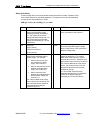
Trunk Drop
A trunk drop topology consists of a single wire, the trunk, with multiple drops coming off
the trunk. The trunk can be the Backplane or long run cable where the drops are then
connected to the trunk. When the trunk is a Backplane, the drops will connect using
QCPort Interconnect cables from the devices on the Backplane. When the trunk is a long
run cable, a D77E-QPLR (biasing resistor and power tap) is used to change the long run
into either a Backplane or QCPort Interconnect cable connection. The biasing resistor
portion of the D77E-QPLR is capable of being switched on or off. When used as a drop
point in a long run cable application, the biasing resistor will most likely be switched off.
The rules to be aware of when designing a Trunk Drop system are that the maximum
drop cannot exceed 1 foot [0.3 meter], and that the sum of the drops cannot exceed 20
feet [6 meters].
MN05001002E
For more information visit www.eatonelectrical.com
Page 14
Intelligent Technologies QCPort System Install Manual
November 2005
Methods of connection include using QCPort Interconnect Cable, QCPort Backplane,
Long Run, or any combination of the three.
Physical Placement
When planning the connection, care should be taken as to the physically placement of
the devices. Considerations include:
•
Grouping IO to utilize the Backplane.
•
Grouping devices that only use the QCPort Interconnect cable.
•
Changing media as little as possible.
For most applications, it will be possible to require only one change in media.
MN05001002E
For more information visit www.eatonelectrical.com
Page 15
Intelligent Technologies QCPort System Install Manual
November 2005
Using Biasing Resistors
Depending on the type of QCPort system being implemented, biasing resistors may or
may not be required. For Figure 1 and Figure 2 under the “Interconnectivity Using
QCPort” section (One Device Using QCPort), a single biasing resistor is required when
the total length of the system is less than 3 feet [1 meter].
When connecting a Network Adapter to IO and motor controllers, as in Figure 3 Multiple
Devices Being Controlled And Monitored Remotely Using QCPort, biasing resistors are
required on the end furthest from the network Adapter. A biasing resistor is not required
on the one end that the Network Adapter is located since the Network Adapter has a
biasing resistor integral.
When a biasing resistor is required, use part # D77E-TERRJ or D77E-QPLR. These
biasing resistors connect between A and B and require 24V DC present on QCPort to be
functional. The D77E-QPLR has three connections to QCPort. They are through the RJ
connectors at the bottom, the Backplane connector on the back, and then through the
front connector at the A and B terminals. The D77E-TERRJ has only one way to connect
to QCPort, which is through the RJ connectors. There are two connectors that are in
parallel with each other so it is not important which way the biasing resistor is orientated.
D77E-QPLR
PP+
D77E-TERRJ
Aux
Power
+
A
B
QCPort
Com
+
PP+
-
24V DC
+
Figure 10: QCPort Biasing Resistor Options
MN05001002E
For more information visit www.eatonelectrical.com
Page 16
Intelligent Technologies QCPort System Install Manual
November 2005
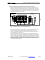
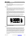
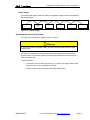
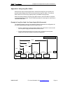
Application Example
IT. 24V DC
Power Supply
Figure 11: Distributed Motor Control Panel
In this Distributed Motor Panel application example, there are two types of interconnect
media being used. The IO and Network Adapter use the Backplane Interconnect while
the motor starters use the QCPort Interconnect cables. In this example, the QCPort
power is supplied through the D77E-QPLR biasing resistor (last module), and the change
from the backplane to the QCPort Interconnect cable is performed there as well.
When powering the QCPort system, the power supply that provides power to the starters
is the same power supply that provides power to the QCPort system. It is important to
size the power supply for the load of the starters and the QCPort load in this application.
Another configuration would include an Automation power supply for the QCPort
components only, and a separate power supply for the IT starters.
All the devices within this example can and will work as designed using one power
supply. For reasons of isolation, a separate DeviceNet power supply would be required
to power the DeviceNet products.
MN05001002E
For more information visit www.eatonelectrical.com
Page 17
Intelligent Technologies QCPort System Install Manual
November 2005
Planning a QCPort Interconnect System
Guidelines for Supplying Power
Use the following guidelines to protect your devices and achieve the best results when
supplying power to the QCPort interconnect system.
IT. Power Supplies
The IT. family of products includes power supplies that meet the needs of the QCPort
devices and motor control. The same power supply that is used for the IT. motor
controller line is applicable to the QCPort system.
Other Power Supplies
When selecting a power supply from another vendor, use the following guidelines:
•
Use power supplies rated at 24V
•
Select a power supply that provides sufficient current for all attached nodes.
Note: In the U.S. and Canada, be sure to adhere to NEC and CE Code limits
respectively.
•
Use a power supply that has its own current limit protection.
•
Make sure you derate the supply for temperature using the manufacturer’s
guidelines.
•
Provide fuse protection for each segment of the cable system; any section
leading away from a power supply must have protection (can be part of the
power tap).
Power Ratings
The power capabilities of the QCPort interconnect system include:
•
Power supplies rated at 24V DC.
•
Long Run cables rated for 4 A steady state.
•
Interconnect Cables rated for 1.0 A steady state.
•
Backplane rated for 6 A steady state.
Notice
Check your national and local codes for additional information. In the United States
and Canada, the QCPort cable system must be installed as a Class 2 circuit. This
requires limiting the current to 4 A.
QCPort Interconnect Cable Rating
The QCPort Interconnect rating is 1.0 A, but the allowable current depends on the length
of the run. The maximum current decreases as the QCPort Interconnect cable length
increases, as indicated in the table below.
MN05001002E
For more information visit www.eatonelectrical.com
Page 18
Intelligent Technologies QCPort System Install Manual
November 2005
Table 3: RJ Interconnect Maximum Current
QCPort Interconnect Cable
Allowable Current
10 [25] inch [cm]
3 [1] feet [meter]
6 [2] feet [meter]
10 [3] feet [meter]
1.0 A
1.0 A
1.0 A
1.0 A
The voltage range between +24 and G must be between 18 and 28V DC.
Locating a Power Supply
The QCPort interconnect system allows several options for supplying power, as outlined
in this section. To determine which option meets your needs, consider the distribution of
the loads, power supply location, and the number of power supplies used. Power
supplies must be 24 volts.
Notice
In the United States and Canada, the power supply must also be Class 2.
Warning
Whenever two or more power supplies are connected to the same segment, the
ground for the system must be referenced to only one point.
MN05001002E
For more information visit www.eatonelectrical.com
Page 19
Intelligent Technologies QCPort System Install Manual
November 2005
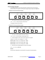
1 Power Supply
Locate the power supply at the end, middle, or anywhere along the cable, as illustrated in
the following figure.
Biasing resistor
Device
Power
Supply
Device
Device
Biasing resistor
Figure 12: 1 Power Supply
Grounding the Interconnect System
You must ground the QCPort system at only one location.
Warning
If you use more than one power supply, all of them should be attached to the same
earth ground.
Ground the G conductor at only one place at the power supply that is closest to the
physical center of the QCPort system to maximize the performance and minimize the
effect of outside noise.
To ground QCPort:
•
Connect the G wire to earth ground using a 1 in (0.25 mm) copper braid or a #8
AWG wire up to 10 ft (3 m) maximum in length.
•
Use the same wire to connect the power tap to earth ground.
MN05001002E
For more information visit www.eatonelectrical.com
Page 20
Intelligent Technologies QCPort System Install Manual
November 2005
Sizing a Power Supply
It is important to verify that the power supply is properly sized for the load and the length
of the QCPort system. To calculate if the placement and the size of the power supplies
are adequate, refer to the examples in the Using the Sizing Calculation on page 23.
Supplying Power
Follow these guidelines to protect your nodes and to achieve the best results when
supplying power to the QCPort cable system.
•
Use power supplies rated at 24V.
•
Select a power supply that provides sufficient current for all attached nodes.
•
Make sure you derate the power tap and the power supply for the expected
temperature using the manufacturer’s guidelines.
•
Use a power supply that has its own current limit protection.
Adjusting the Configuration
When the sections have a voltage drop less than 4.65V, your configuration will operate
properly. Ideally, the voltage drops for each section should be within 10%. If one section
has a substantially greater voltage drop than the other, you should attempt to balance the
load of the cable system by moving the power supply or nodes. Some ways to make
your system operational include the following:
•
Shorten the overall length of the cable system.
•
Move the power supply in the direction of the overloaded section.
•
Move devices from the overloaded section to another section.
•
Move higher current loads as close to the supply as possible.
•
Add a second power supply to the cable system.
•
Break the QCPort system into two separate networks to reduce the number of
nodes on each.
MN05001002E
For more information visit www.eatonelectrical.com
Page 21
Intelligent Technologies QCPort System Install Manual
November 2005
Sizing Calculation
A power supply that is not end connected creates two sections of cable. Because of this,
each section needs to be evaluated separately. The equation sums the calculated drop
for each device and compares it to 4.65V.
SUM {[(Ln x Rc) + (Nt x (0.005))] x In } <= 4.65V
Term
Definition
Term
Definition
Ln
L = The distance (ft) between the
device and the power supply,
excluding the drop line distance.
n = The number of the device
being evaluated, starting with 1 for
the device closest to the power
supply and increasing by 1 for the
next device.
(0.005)
The nominal-contact resistance used for
every connection to the trunk line.
Rc
Long Run
4.65V
The maximum voltage drop allowed.
This is the total cable system voltage
drop of 5.00V minus 0.35V reserved for
drop line voltage drop.
In
I = The current drawn from the cable
system by the device. For currents
within 90% of the maximum, use the
nominal device current. Otherwise, use
the maximum rated current of the device.
0.021 (ohm/ft)
QCPort Interconnect
0.105 (ohm/ft)
Nt
The number of taps between the
device being evaluated and the
power supply. For example:
•
When a device is the first
one closest to the power
supply, this number is 1.
•
When a node has one device
between it and the power
supply, this number is 2.
•
When 10 devices exist
between the evaluated node
and the power supply, this
number is 11.
For a device attached as a drop from a
device, the currents for the trunk and
drop device should be summed and
counted as one tap.
n = The number of devices being
evaluated, starting with 1 for the device
closest to the power supply and
increasing by 1 for the next device.
For a device attached as a drop
from a device, the currents for the
trunk and drop device should be
summed and used with the
equation only once.
MN05001002E
For more information visit www.eatonelectrical.com
Page 22
Intelligent Technologies QCPort System Install Manual
November 2005
Using the Sizing Calculation
The following examples use the sizing calculation to determine if the power supply is
placed correctly in the system and if the power supply is large enough for the application.
Example 1 End Connected Power Supply
1 foot
PS
1 foot
T
1 foot
1 foot
D1
0.1A
D2
1.1A
1 foot
T
D3
0.3A
1. Sum up all the currents (QCPort Interconnect system)
=0.1 + 1.1 + 0.3 = 1.5A (too much for Interconnect)
The supply will have to be relocated.
Example 2 End Connected Power Supply
10 foot
PS
10 foot
T
10 foot
D1
0.1A
10 foot
D2
0.4A
10 foot
D3
0.3A
T
1. Sum up the currents (QCPort Interconnect system)
=0.1 + 0.4 + 0.3 = 0.8 A (OK since 10 feet allows 1.0A)
2. Find the voltages for each node using the equation for Long Run.
SUM {[(Ln x (0.105)) + (Nt x (0.005))] x In } <= 4.65V
Device 1 [(20 x (0.105)) + (1 x (0.005))] x 0.1 = 0.21V
Device 2 [(30 x (0.105))+ (2 x (0.005))] x 0.4 = 1.26V
Device 3 [(40 x (0.105)) + (3 x (0.005))] x 0.3 = 1.26V
3. Add each Devices voltage together to find the total voltage.
0.21 + 1.26 + 1.26 = 2.73V (OK)
Results
Since the total voltage does not exceed 4.65V, the system will operate properly.
MN05001002E
For more information visit www.eatonelectrical.com
Page 23
Intelligent Technologies QCPort System Install Manual
November 2005
Example 3 Middle Connected Power Supply
3 foot
T
3 foot
D1
.2 A
3 foot
D2
.3 A
3 foot
D3
.1A
0 foot
PS
Section 1
0 foot
D4
1A
T
D5
2A
Section 2
2. Sum up the currents per section
Section 1 (QCPort Interconnect) = 0.2 + 0.3 + 0.1 = 0.6 A (OK)
Section 2 (Backplane) = 1.0 + 2.0 = 3.0 A (OK)
Find the voltages for each device using the equation for Long Run.
SUM {[(Ln x (0.105)) + (Nt x (0.005))] x In } <= 4.65V
Device 1 [(9 x (0.105)) + (3 x (0.005))] x 0.2 = 0.19V
Device 2 [(6 x (0.105))+ (2 x (0.005))] x 0.3 = 0.19V
Device 3 [(3 x (0.105)) + (1 x (0.005))] x 0.1 = 0.03V
Device 4 [(0 x (0.105)) + (1 x (0.005))] x 1.0 = 0.00V
Device 5 [(0 x (0.105)) + (2 x (0.005))] x 2.0 = 0.02V
Add each Devices voltage together to find the total voltage per section.
Section 1 – 0.19+0.19+0.03 = 0.41V (OK)
Section 2 – 0.00+0.02 = 0.02V (OK)
Results
Since the total voltage does not exceed 4.65V in either section, the system will operate
properly.
MN05001002E
For more information visit www.eatonelectrical.com
Page 24
Intelligent Technologies QCPort System Install Manual
November 2005
Troubleshooting and Maintenance
Refer to the selected device manuals for more detailed hints on troubleshooting.
MN05001002E
For more information visit www.eatonelectrical.com
Page 25
Intelligent Technologies QCPort System Install Manual
November 2005
Appendix A: Using Long Run Cables
When devices require locating further than 100 feet [30 meters] from one another, the
physical media changes from QCPort Interconnects to Long Run cables. This cable is
better rated for current carrying capacity and for the RS485 communication.
When connecting between Long Run and a QCPort device, the D77E-QPLR is required
to change the physical media. The D77E-QPLR provides for screw lugs for connection to
industrial RS485 cable.
Example of Long Run Cable: One Power Supply (End-Connected)
The following example uses the full calculation method to determine the configuration for
one end-connected power supply on a thick cable trunk line.
•
Device 1 and Device 2 cause the same voltage drop, but Device 2 is twice as far
from the power supply and draws half as much current.
•
Device 4 draws the least amount of current, but it is farthest from the power
supply and causes the greatest incremental voltage drop.
T – Biasing resistor
95 ft
43 ft
36 ft
18 ft
T
T
Power
Supply
Device 1
1.0 A
Device 2
0.5 A
Device 3
0.4 A
Device 4
0.3 A
Figure 13: Example of Long Run Cable: One Power Supply (End-Connected)
MN05001002E
For more information visit www.eatonelectrical.com
Page 26
Intelligent Technologies QCPort System Install Manual
November 2005
1. Find the voltages for each node using the equation for Long Run.
SUM {[(L n x (0.0045)) + (N t x (0.005))] x I n } <= 4.65V
Device 1 [(18 x (0.021)) + (1 x (0.005))] x 1.0 = 0.383V
Device 2 [(36 x (0.021))+ (2 x (0.005))] x 0.5 = 0.383V
Device 3 [(43 x (0.021)) + (3 x (0.005))] x 0.4 = 0.367V
Device 4 [(95 x (0.021)) + (4 x (0.005))] x 0.3 = 0.604V
2. Add each Devices voltage together to find the total voltage.
0.383V + 0.383V + 0.367V + 0.604V = 1.737V
Results
Since the total voltage does not exceed 4.65V, the system will operate properly.
MN05001002E
For more information visit www.eatonelectrical.com
Page 27
Intelligent Technologies QCPort System Install Manual
November 2005
Technical Support
For additional information on this product,
Please call our Customer Support Center at:
1-800-356-1243
For service or start-up assistance
24 hours/day, 7 days/week,
please call:
1-800-498-2678
MN05001002E
For more information visit www.eatonelectrical.com
Page 28
Intelligent Technologies QCPort System Install Manual
November 2005
Company Information
Eaton Electrical Inc. is a global leader in electrical control, power distribution and
industrial automation products and services. Thorough advanced product development,
world-class manufacturing methods, and global engineering services and support, Eaton
Electrical® provides customer-driven solutions under band names such as CutlerHammer®, Durant®, Heinemann®, Holec® and MEM®, which globally serve the
changing needs of the industrial, utility, light commercial, residential and OEM markets.
For more information visit www.eatonelectrical.com.
Eaton Corporation is a global diversified industrial manufacturer with 2003 sales of $8.1
billion that is a leader in fluid power systems, electrical power quality, distribution, and
control; automotive engine air management and fuel economy; and intelligent drivetrain
systems for fuel economy and safety in trucks. Eaton has 51,000 employees and sell
products in more than 50 controls. For more information visit www.eaton.com.
Eaton Electrical
1000 Cherrington Parkway
Moon Township, PA 15108-4312
USA
Tel: 1-800-525-2000
www.eatonelectrical.com
MN05001002E
©2004 Eaton Corporation
All Rights Reserved
Printed in USA
Publication No MN05001002E
November 2005
For more information visit www.eatonelectrical.com
Page 29