1
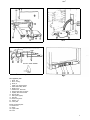
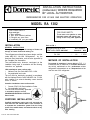
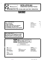
REFRIGERATOR FOR LP-GAS AND ELECTRIC OPERATION
RA1302
FOR YOUR SAFETY
If you smell gas:
1. Open windows.
2. Don’t touch electrical switches.
3. Extinguish any open flame.
4. Immediately call your gas supplier.
Installation
Instructions for use
Gas equipment
Electric equipment
Maintenance
Fault tracing
FOR YOUR SAFETY
Do not store or use gasoline or other
flammable vapors and liquids in the
vicinity of this or any other appliance.
quality leisure line products
Corporate Office
2320 Industrial Parkway Elkhart, IN 46515
USA
SALES OFFICES
Zone 1
Elkhart, IN 46515
2320 Industrial Pkwy.
Phone: 219-295-5226
Zone III
City of Industry, CA 91746
14441 Bonelli Street
Phone: 616-968-9431
CANADA
Dometic Distribution inc.
866 Langs Drive
Cambridge, Ontario
N3H 2N7 Canada
Phone: 519-653-4390
Zone II
Arlington, TX 76011
2920 Avenue “E” East
Phone: 817-649-5726
820454000
820 4540-00
Page
4
5-6
6
6
7
7
REFRIGERATORS WITH
PIEZO IGNITER
Fig. 1
Fig. 2
Clear blue colour of flame
Fig. 3
Gas equipment parts
1. Burner tube
2. Burner housing
3. Burner jet
4. Feeler point (thermocouple)
5. Flame failure safety device
6. Bypass screw
7. Gas/Electrical thermostat
6. Pressure test gage connection
9. Capillary tube for thermostat
10. Shut-off valve
11. Piezo igniter (lighter)
12. Electrode
19. Burner fixing screw
24. Hexagon nut
26. Cover plate
Electric equipment parts
13. Flexible cord
14. Switch
18. Lighter cable
22. Cover
3
INSTALLATION
GENERAL INSTRUCTIONS
This appliance Is designed for storage of foods and storage
of frozen foods and making ice.
The refrigerators outlined have been design certified under ANS
/Z21.19a-1984. Refrigerators, by the American Gas Association,
and are also approved by the Canadian Gas Association.
The certifications are, however, contingent on the installation
being made in accordance with the following instructions as
applicable.
The Installation must in the USA conform with:
1. National Fuel Gas Code ANSI 2223.1-1984.
2. Any applicable local code.
The unit must be electrically grounded in accordance with the
National Electric Code ANSI/NFPA No. 70-1984 when installed if
an external alternating current electrical source is utilized.
The installation must in Canada conform with:1. Current CGA B 149 Gas Installation Codes.
2. Any applicable local code.
The unit must be electrically grounded in
accordence with the current
CANADIAN ELECTRICAL CODE C22
Pans 1 and 2.
Free-standing models for floor installation
only
GAS CONNECTION
Hook-up to the gas supply line is accomplished at the manual
gas valve, whiih is furnished with a 3/8" SAE (UNF 3/8" 18) male
flare connection. All completed connections should be checked
for leaks with soapy water.
The gas supply system must incorporate a pressure regulator to
maintain a supply pressure of not more than 11 inches water
gage.
When testing the gas supply system at test pressures in excess
of 1/2 psi9 the refrigerator and its individual shutoff valve must be
disconnected from the gas supply piping system.
When testing the gas supply system at pressures less or equal 1/2
psig the applii must be isolated from the gas supply piping
system by closing its individual manual shutoff valve.
In case detailed instructions on the installation and connection to
the gas supply are required, contact your dealer or distributor.
ELECTRICAL CONNECTION
120 Volts AC
The refrigerator is equipped with a three prong (grounded) plug
for protection against shock hazards and should be plugged
directly into a properly grounded three prong receptacle. Do not
cut or remove the grounding prong from this plug. The cord
should be routed to avoid coming in contact with the burner cover
flue cover or other hot components.
SPECIAL HINTS
Ensure that there is a free space of at least 4 in. (10 cm) above
the refrigerator and see that the ventilation opening on top of the
cabinet is not covered in any way.
Do not place the refrigerator in a space where air circulation is
restricted.
A clearance of at least 25 mm should be left between the rear
and sides of the refrigerator and the surrounding walls.
This free-standing refrigerator requires accessibility to the back
for servicing the gas equipment. If allowed by the Local Authorities, the accessibility can be obtained by using a certified Flexible Metal Connector of Gas Hose Assembly which would allow
the refrigerator to be withdrawn without disrupting the gas supply. However, if the Local Authorities require a rigid gas supply
connector the refrigerator should be located with sufficient space
at the back for servicing or, if located against a wall, a removable
panel of a minimum size of 16x20” should be provided in the
wall to allow access to the back of the refrigerator.
Note. Do not install the appliance directly on carpeting.
Carpeting must be protected by a metal or wood panel
beneath the appliance which extends at least full width and
depth of the appliance.
The refrigerator must be installed in level. A spirit level is supplied
with each refrigerator.
Feet
TEST OF THE GAS SAFETY SHUTOFF
The gas safety shutoff device must be tested after the refrigera-
Some of the freestanding models come with 4 plastic feet.
These feet should be mounted on the underside to ensure free
air circulation around the cooling unit.
CLEARANCES
Minimum clearances in inches to combustible materials are:
G: Top 4
Clearance M between the rearmost part
K: Side 1
of the refrigerator and the wall
L: Bottom 0
behind the refrigerator.
M: Rear 1
TO REMOVE AND REPLACE
THE REFRIGERATOR
Before working on the refrigerator make sure that 120 V A. C.
leads are disconnected. Shut the gas valve. Unscrew the hexagon nut 24 and move the valve on the gas line out off the
bracket. Check that the valve slips out of the clip connection with
the switch shaft. After reassembly the gas connection should be
checked for leaks with soapy water.
tor is placed in operation.
Do as follow:
1. Start the refrigerator according to the instruction for gas operation with piezo igniter (fig. 4).
2. Check that the gas flame is lit. This can be observed through
the reflector E.
3. Close the gas valve by turning the knob A back to position
“OFF”.
4. Wait 1 minute.
5. Remove cover plate, see (26) in fig. 2. Open the gas valve by
turning the knob A to position “GAS’ without pushing the
button C and D. Test that no gas comes through the jet, item 3
in fig. 1 or 2. Use soapy water. Be careful not to damage the
jet.
6. After test rinse the jet with water. Once more be careful not to
damage the jet. Assamble the cover plate. Start the refrigerator by following the instruction for gas operation.
Normal gas operation should now return. Operate for
at least 5 minutes.
INSTRUCTIONS FOR USE
HOW TO START THE REFRIGERATOR
Leveling
In the boiler ammonia vapor is distilled from an ammonia-water
mixture and carried to the finned condenser, where it tiiuifies.
The liquid flows to the evaporator, where it creates cold by
evaporating into a circulating flow of hydrogen gas. If the evaporator coil is not level the liquid readily accumulates, forming pockets which can impair the gas circulation or even block it, in which
case, of course, the cooling will stop.
If the refrigerator is properly installed, e e the freezer shelf parallel to the floor, the refrigerator will then also perform well.
Gas Operation (Fig. 4)
1. To start the refrigerator turn the knob A to position “GAS”.
2. Turn the thermostat knob B to setting 4.
.3. Push the button C to stop and push the button D of the piezo
igniter. The pushing has to be repeated until the gas is lit at
the burner. This can be observed through the reflector E.
4. After the gas is lit keep the button C pushed for 10 seconds.
Release the button and check through the reflector that the
burner flame stays burning. If not repeat the lighting procedure.
To shut off the‘refrigerator turn the knob A to off position.
NOTE: As soon as the necessary cold temperature in inside
the cabinet has been reached, adjust the thermostat
knob to required setting.
Electric Operation (Fig 4)
1. Check that the attachment plug is correctly connected to the
main supply.
2. Turn the knob A to desired position for electric operation.
3. Turn the thermostat knob B to setting 4.
To shut off the refrigerator turn the knob A to off position.
HOW TO USE THE REFRIGERATOR
Food Storage Compartment
The food storage compartment is completely closed and
unventilated, whiih is necessary to maintain the required low
temperature for food storage. Consequently foods having a
strong odor or liable to absorb odors should be covered. Vegetables, salads etc should be covered to retain their crispness.
The coldest positiins in the refrigerator are underneath the cooling evaporator and at the bottom of the refrigerator, and the least
cold positions are on the upper door shelves. This should be
considered when diierent types of food are placed in the
refrigerator.
Defrosting
When the frozen food storage compartment is covered with frost
the refrigerator must be shut down temporarily till the frost is
melted.
Empty the refrigerator leaving the drip tray under the finned
evaporator and the cabinet and freezer doors open. If desired,
defrosting may be speeded up by filling the ice tray with hot water
and placing it in the freezer.
When all frost is melted, empty the drip tray and dry the interior of
the refrigerator with a clean cloth.
Replace the drip tray and ice tray, replace all food stuffs and set
the thermostat to MAX for a few hours.Then reset the thermostat
knob to its normal position.
Before the refrigerator is restarted the compartment should be
dried, the ice trays washed and refilled with fresh water:
When the frost on the finned evaporator section has melted
water will be collected in the drip tray. The drip tray should be
emptied at regular intervals.
5
Frozen Food Storage Compartment
The ice trays should be placed in direct contact with the freezer
shelf for fastest ice making. Quick frozen soft fruits and ice cream
should be placed in the coldest part of the compartment which is
on the shelf or just below it. Frozen vegetables, on the other
hand, may be stored in any part of the compartment.
The compartment is not designed for the deep or quick freezing
of foodstuffs. Meat or fish foods, whether raw or prepared, and
provided they are precooled in the refrigerator, can however,
also be stored in the frozen food storage compartment. They can
then be stored about three times as long as in the fresh food
storage compartment. To prevent drying out, keep food in coverd
dishes, in plastic bags or wrapped in aluminium foil.
Ice Making
Ice cubes can be made in the ice trays which should be filled with
water to within 1/4" (5 mm) from the top. To release the ice cubes
seize the tray with both hands and twist the tray. Cubes not
reguired should preferably be replaced in the tray. Refill the tray
with water and replace the tray on the freezer shelf.
Ice making is accelerated if the thermostat knob is turned to
setting “MAX”. It is a good idea to do this a few hours before an
anticipated need for ice but be sure to turn the knob back to
normal setting when the ice is formed or the foodstuffs in the
cabinet may become frozen hard.
To Shut Off the Refrigerator
To shut off the refrigerator turn the knob A to off position. If the
cabinet is not in operation over a period of weeks, it should be
emptied and cleaned and the door left ajar. The ice trays should
also be dried and kept outside the cabinet.
Cleaning
To clean the interior lining of the refrigerator use lukewarm weak
soda solution. The evaporator, ice trays and shelves must,
however, be cleaned with warm water only. Never use strong
chemicals or abrasives to clean these parts or the protective
surface will be spoiled. It is important always to keep the
refrigerator clean.
The Flame Failure Safety Device (Fig. 3)
The feeler of the thermo couple shall reach in over two slots of
the burner. To replace the thermo couple proceed as follows:
1. Remove the plastic cover 22 (Fig. 5).
2. Unscrew plug 20 and pull thermocouple straight out (Fig. 3).
3. Remove spring 21 (Fig. 3).
4. Pull out thermocouple sideways from burner housing.
5. Bend the new thermo-couple to the same shape as the old
one.
6. Reassemble in reverse order. Check that feeler has been
correctly refitted in relation to burner. See Fig. 3.
7. Mount plug 20, taking care not to damage the threaded hole
in the aluminium cap of the housing. The plug must be property tightened to the valve housing to ensure good contact
between the thermocouple and the magnetic coil within the
housing.
The Thermostat
me refrigerator is equipped with a thermostat which is regulated
by turning the knob to different settings in order to obtain the
desired controlled cabinet temperature.
At OFF Under normal operating conditions the thermostat
valve remains closed and the burner is running continuously at the by-pass rate, just enough to keep the
burner lit.
At MAX The thermostat valve remains open and the burner is
running continuously at full gas rate. Lowest cabinet
and freezer temperatures are obtained at this setting.
Between these two extrems is a numbered proportion of the dial
over which various controlled temperatures can be obtained, the
higher the number, the lower the temperature.
As soon as the required cold temperature inside the cabinet is
reached, the thermostat cuts the burner main flame leaving the
by-pass flame to keep the safety valve open.
The Igniter
The refrigerator is fitted with a piezo igniter (see fig. 4) which
does not normally need any maintenance. If the igniter does not
work properly contact an authorized service point.
Do not store explosive substances in the refrigerator, such
as cigarette lighter gas, petrol, ether or the like.
ELECTRIC EQUIPMENT
Cartridge heater
GAS EQUIPMENT
Flue Top and Baffle
The flue baffle is suspended from the top and must be in position
in the central tube of the cooling unit.
6
This refrigerator is equipped also for electric operation, 120 Volts
A C.
The heat necessary for the operation of an absoprtion type cooling unit is supplied by an electric cartridge heater mounted in a
pocket of the boiler system.
To replace the heater first of course check that the wall plug is
disconnected. Then proceed as follow:
1. Remove the plastic cover (22) of the main control structure by
loosening the two screws.
2. Disconnect the heater leads.
3. Pull off the metal hose.
4. With a pair of pliers unfold the lug holding the Iii of the boiler
casing and open the lid.
5. Remove some insulation wool so that the heater is
accessible.
6. Turn and lift the heater out of its pocket.
7. Fit the new heater into the pocket and pull on the hose around
the leads.
6. Connect the leads and put on the plastic cover.
9. Reset the insulation and close the lii of the boiler casing.
functioning of the burner. Clean baffle and flue. Further. clean
cooling unit and floor under refrigerator.
The entire gas installation should be checked for leaks at intervals. Test all pipe connections with soapy water, not with an
open flame.
NOTE. Any service of the gas controls, with exeption for the
above mentioned replacement, maintenance and cleaning
operations must be performed by an authorized service
center only.
The Switch
The electric control also comprises an on-off switch operated by
the selector knob at the front panel. The switch has a “on”position for 120 Volts A C.
The Thermostat
The electric thermostat is combined with the gas thermostat and
is thus operated by the knob B at the front panel. The temperature in the refrigerator can be regulated by turning the thermostat
knob to higher or lower numbers. Although the exact setting is
not critical choose a setting at which the frost which gradually
forms on the cooling evaporator is just maintained in dry condition.
It will be necessary to set the thermostat knob one or two numbers higher when the ambient temperature becomes higher or
the load unusually heavy.
If less cooling is required a lower setting should be chosen.
PERIODIC MAINTENANCE
NOTE. Before working on the refrigerator make sure that 120 V
A.C. leads are disconnected.
Shutoff gas valve.
The Burner and the Burner Jet (Fig. 2)
The colour of the flame shall be clear blue over the slots of the
burner (Fig. 3).
Once or twice a year depending on use, it is necessary to clean
and adjust the burner assembly. Proceed as follows:
1. Loosen screw and remove cover plate for burner housing.
2. Disconnect lighter cable from the electrode.
3. Loosen burner fixing screw 19 and withdraw burner.
4. Clean burner tube with a brush. Blow with compressed air.
5. Screw off jet and clean with alcohol. Blow with compressed
air. Never use a needle or similar.
6. Reassemble.
7. Be careful that the end of the burner fits into the slot on the
bracket.
The slots of the burner must be centrally located under the boiler
tube.
The Electrode
For a proper ignition function it is necessary to keep the electrode
insulation dry and free from din. The gap between burner tube
and electrode shall be max. 3/16" (5 mm) and min. 1/8" (3 mm).
WARNING
If the refrigerator is used intermittently it should be checked at
least once a year.
It is important to keep the appliance area clear and free from
combustible materials, gasoline and othet flammable vapors and
liquides. The flow of combustion and ventilating air must not be
obstructed. Check the flue baffle that it is clean and reasonably
free from soot. Heavy soot formation indicates improper
FAULT TRACING
The refrigerator does not freeze
satisfactorily
Causes and remedies
a) Jet orifice clogged. Unscrew jet and blow clear or wash in
alcohol. Do not use wire or pin to clean orifice.
b) Check the leveling of the refrigerator.
c) Flame has gone out. Remedy: 1) Gas in bottle is used up refill. 2) Feeler point of the flame failure safety device is not
heated enough by flame - check against fig. 2 or 3.
3) Clogged by-pass screw - clean or exchange it.
d) Air circulation around cooling unit is restricted. Be sure that
refrigerator is properly ventilated.
e) The evaporator is heavily coated with frost. Defrost.
f) Flue baffle not inserted into the central tube of the cooling
unit.
g) The thermostat is incorrectly used. See paragraph on thermostat. In hot weather the setting should be one or two numbers “colder” than usual.
h) Gauze in burner head clogged. Clean.
i) Burner damaged. Replace.
i) Burner may be dislocated. Relocate.
k) Wrong gas pressure at the burner. Have pressure checked at
burner and at gas bottle. Pressure at burner must not fall
below 11 ‘W.G. when thermostat is set on MAX.
ODOR FROM FUMES
Causes and remedies
a. The flame touches side of the boiler due to dislocation of the
burner. Relocate. Burner dislocation may also cause smoke
and discoloring of walls and ceiling.
b. Burner damaged. Replace.
c. The flame touches flue baffle. Remedy: 1) Burner damaged.
Replace. 2) Flue baffle too low. Correct the position of the
baffle.
d. The flue tube is dirty. Clean flue as follows. Cover burner and
jet. Remove flue top and baffle. Clean flue with special flue
brush. Clean baffle before putting back in place.
All the above instructions are to be followed closely. The
refrigerator is quality-guaranteed. However, we are not responsible for any failures caused by improper adjustments and
unfavorable installation conditions. Contact service point or distributor service dept. for assistance.
Replacement Parts Suppliers: See cover.
7
El9
D 0 111 e t 1 c
I
INSTALLATION INSTRUCTIONS
(Addendum) WHERE REQUIRED
BY LOCAL AUTHORITIES
REFRIGERATOR FOR LP-GAS AND ELECTRIC OPERATION
MODEL RA 1302
FOR YOUR SAFETY
FOR YOUR SAFETY
If you smell gas:
1. Open windows.
Do not store or use gasoline or other
flammable vapors and liquids in the
vicinity of this or any other appliance.
2. Don’t touch electrical switches.
3. Extinguish any open flame.
4. Immediately call your gas supplier.
INSTALLATION
GENERAL INSTRUCTIONS
This appliance is designed for storage of foods and
storage of frozen foods and making ice.
The refrigerators outlined have been design certified
under ANS 221 .19a-1984 Refrigerators, by the
American Gas Association, and are also approved by
the Canadian Gas Association.
The certifications are, however, contingent on the
installation being made in accordance with the following
instructions as applicable.
USA installations must conform with:
Refer to FIG. 1.
INSTALLATION WITH ROOF
VENT AND LOWER SIDE VENT
RA 1302
MIN. HEIGHTS
INCHES 1 MM
I
62
I 1575 I
METHOD OF INSTALLATION
The method of installation is shown below in FIG. 1. It
is essential that all maximum or minimum dimensions
are strictly maintained as the performance of the
refrigerator is dependent on an adequate flow of air
over the rear of the refrigerator.
1. National Fuel Gas Code ANSI Z223.1-1984.
2. Any applicable local code.
The unit must be electrically grounded in accordance
with the National Electric Code ANSI/NFPA No. 70-1964
when installed if an external alternating current electrical
source is utilized.
Canadian installations must conform with:
1. Current CGA B 149 Gas Installation Codes.
2. Any applicable local code.
The unit must be electrically grounded
FIG. 1
in accordance with the current
CANADIAN ELECTRICAL CODE C22
Parts 1 and 2.
CERTIFIED INSTALLATION
Certified installations require one roof vent and one
lower side vent and shall be made in such a manner as
to separate the combustion system from the living
space of the mobile home, recreational vehicle or any
other dwelling.
Form No. 820 4540-00-ADD 5/89
ENSER
SPECIAL HINTS
NOTE: Do not install the appliance directly on
carpeting. Carpeting must be protected by a metal
or wood panel beneath the appliance which extends
at least full wldth and depth of the appliance.
The refrigerator must be installed in a substantial
enclosure and must be level. A spirit level is supplied
with each refrigerator and by placing it in the freezer
compartment one can level the refrigerator both ways,
front to back and side to side. When installing the
refrigerator in the enclosure care should be taken to
ensure a complete sealing between the casing of the
refrigerator and the top, sides and bottom of the
enclosure.
GAS CONNECTION
Hook-up to the gas supply line is accomplished at the
manual gas valve, which is furnished with a 3/8’ SAE
(UNF 5/8’ - 18) male flare connection. All completed
connections should be checked for leaks with soapy
water.
The gas supply system must incorporate a pressure
regulator to maintain a supply pressure of not more
than 11 inches water gauge.
When testing the gas supply system at test pressures
in excess of 1/2 psig, the refrigerator and its individual
shutoff valve must be disconnected from the gas supply
piping system.
When testing the gas supply system at pressures less
than or equal to 1/2 psig, the appliance must be
isolated from the gas supply piping system by closing
its individual manual shutoff valve.
In case detailed instructions on the installation and
connection to the gas supply are required, contact your
dealer or distributor.
ELECTRICAL CONNECTION
120 Volts AC
The refrigerator is equipped with a three prong
(grounded) plug for protection against shock hazards
and should be plugged directly into a properly
grounded three prong receptacle. Do not cut or remove
the grounding prong from this plug. The cord should be
routed to avoid coming in contact with the burner cover,
flue cover or other hot components.
TO REMOVE AND REPLACE THE
REFRIGERATOR
Before working on the refrigerator make sure that 120
V AC leads are disconnected. Shut the gas valve.
Unscrew the hexagon nut 24 and move the valve on the
gas line out off the bracket. Check that the valve slips
out of the clip connection with the switch shaft. After
reassembly the gas connection should be checked for
leaks with soapy water.
TEST OF THE GAS SAFETY
SHUTOFF
The gas safety shutoff device must be tested after the
refrigerator is placed in operation.
Do as follows:
1. Start the refrigerator according to the instruction for
gas operation with piezo igniter (FIG. 4, Form 820
4540-00).
2. Check that the gas flame is lit. This can be
observed through the reflector E.
3. Close the gas valve by turning the knob A back to
position ‘OFF’.
4. Wait 1 minute.
5. Remove cover plate, see (26) in FIG. 2. Open the
gas valve by turning the knob A to position ‘GAS’
without pushing the button C and D. Test that no
gas comes through the jet, item 3 in FIG. 1 or 2.
Use soapy water. Be careful not to damage the jet.
6. After test rinse the jet with water. Once more be
careful not to damage the jet. Assemble the cover
plate. Start the refrigerator by following the
instruction for gas operation.
Normal gas operation should now return.
Operate for at least 5 minutes,
FOR INSTRUCTION ON CARE AND USE, REFER TO
FORM NO. 820 4540-00; PAGES 5, 6 & 7.