1
Cat. No. 01017061
Rev. C 09/08/05
DCO # 8404
Installation, Operating
and Service Instructions
with Parts List
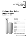
Culligan Gold Series™
Water Softener
Models From 2005
©2005 Culligan International Company
Printed in USA
Attention Culligan Customer:
The installation, service and maintenance of this equipment should be rendered by a
qualified and trained service technician. Your local independently operated Culligan
dealer employs trained service and maintenance personnel who are experienced in the
installation, function and repair of Culligan equipment. This publication is written
specifically for these individuals and is intended for their use.
We encourage Culligan users to learn about Culligan products, but we believe that
product knowledge is best obtained by consulting with your Culligan dealer. Untrained
individuals who use this manual assume the risk of any resulting property damage or
personal injury.
WARNING - Prior to servicing equipment, disconnect power supply to
prevent electrical shock.
WARNING - If incorrectly installed, operated or maintained, this product
can cause severe injury. Those who install, operate, or maintain this
product should be trained in its proper use, warned of its dangers, and
should read the entire manual before attempting to install, operate or
maintain this product.
THIS SYSTEM IS NOT INTENDED TO BE USED FOR TREATING WATER THAT IS
MICROBIOLOGICALLY UNSAFE OR OF UNKNOWN QUALITY WITHOUT
ADEQUATE DISINFECTION BEFORE OR AFTER THE SYSTEM.
CULLIGAN INTERNATIONAL COMPANY
One Culligan Parkway
Northbrook, Illinois 60062-6209
847.205.6000
i
Culligan Gold Series™ Water Softener
Installation, Operating
and Service Instructions
with Parts List
Culligan Gold Series™
Water Softener
Models From 2005
Table of Contents
Page
Important Safety Information ......................................i
Introduction ................................................................2
Performance Specifications ......................................3
Preparation ................................................................4
Basic Principles..........................................................6
Flow Diagrams ..........................................................8
Controller Features ..................................................13
Operation..................................................................14
Installation ................................................................16
Programming............................................................23
Statistical Data ........................................................33
Manual Cycling ........................................................36
Final Start-up............................................................38
Care and Maintenance ............................................40
Error Codes ..............................................................43
Diagnostics ..............................................................44
Troubleshooting........................................................46
Service ....................................................................54
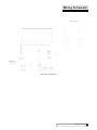
Wiring Schematics ..................................................57
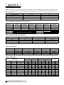
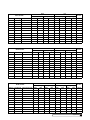
Appendix A - Flow Rates & Capacities ....................58
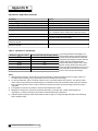
Appendix B - Aqua-Sensor® Application Guidelines 60
Service Parts............................................................62
Table of Contents
1
Introduction
Read this Manual First
Before you operate the Culligan Gold Series™ Water Softening System, read this manual to become familiar with the device
and its capabilities.
Watch for Special Paragraphs
Please read the special paragraphs in this manual. Examples are shown below.
The Culligan Gold Series™ Water Softeners are tested and certified by WQA against NSF/ANSI
Standard 44 for the effective reduction of hardness (calcium and magnesium) as tested and
substantiated by test data.
For installations in Massachusetts, the Commonwealth of Massachusetts Plumbing Code 248 CMR shall
be adhered to. Consult your licensed plumber for installation of the system. This system and its
installation must comply with state and local regulations.
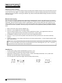
Safe Practices
Throughout this manual there are paragraphs set off by special headings.
NOTE: Check and comply with your state and local codes. You must follow these guidelines.
NOTE: Notice is used to emphasize installation, operation or maintenance information which is important, but does not
present any hazard. Example:
NOTE: The nipple must extend no more than 1 inch above the cover plate.
CAUTION: Caution is used when failure to follow directions could result in damage to equipment or property. Example:
CAUTION! Disassembly while under water pressure can result in flooding.
WARNING: Warning is used to indicate a hazard which could cause injury or death if ignored. Example:
WARNING! Electrical shock hazard! Unplug the unit before removing the cover or accessing any internal
control parts.
Serial Numbers
The control valve serial number is located on the back of the timer case.
The media tank serial number is located on the top surface of the tank.
This publication is based on information available when approved for printing. Continuing design refinement could cause
changes that may not be included in this publication.
NOTE: Do not remove or destroy the serial number. It must be referenced on request for warranty repair or replacement.
Products manufactured and marked by Culligan International Company (Culligan) and its affiliates are protected by patents
issued or pending in the United States and other countries. Culligan reserves the right to change the specifications referred
to in this literature at any time, without prior notice. Culligan, Aqua-Sensor, Tripl-Hull, Flo-Pak and Soft-Minder are
trademarks of Culligan International Company or its affiliates.
2
Culligan Gold Series™ Water Softener
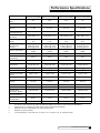
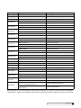
Performance Specifications
9” Model • 1" 5-cycle
Reinforced Thermoplastic
10” Model • 1" 5-cycle
Reinforced Thermoplastic
12” Model • 1" 5-cycle
Reinforced Thermoplastic
14” Model • 1" 5-cycle
Reinforced Thermoplastic
Overall Conditioner
Height
54 in
60 in
58 in
71 in
Media Tank Design
Quadra-Hull™
Quadra-Hull™
Quadra-Hull™
Quadra-Hull™
9 x 48 in
10 x 54 in
12 x 52 in
14 x 65 in
Salt Storage Tank
Dimensions (Dia x Ht)
16 x 43 in or 18 x 43 in
18 x 43 in
18 x 43 in
24 x 42 in
Exchange Media, Type
and Quantity
Cullex® Media, 1.0 ft3
Cullex® Media, 1.5 ft3
Cullex® Media, 2.0 ft3
Cullex® Media, 3.0 ft3
Cullsan® Underbedding,
12 lb
Cullsan® Underbedding,
15 lb
Cullsan® Underbedding,
20 lb
Cullsan® Underbedding,
25 lb
19,500 gr @ 4.0 lb
28,600 gr @ 8.0 lb
33,200 gr @ 12.0 lb
28,900 gr @ 6.0 lb
38,900 gr @ 12.0 lb
46,800 gr @ 18.0 lb
32,600 gr @ 7.0 lb
61,600 gr @ 18.0 lb
71,700 gr @ 30.0 lb
52,200 gr @ 12.0 lb
76,500 gr @ 24.0 lb
92,600 gr @ 36.0 lb
4,890 gr/lb @ 4 lb salt
dosage
4,800 gr/lb @ 6 lb salt
dosage
4,60 gr/lb @ 7 lb salt
dosage
4,350 gr/lb @ 12 lb salt
dosage
Freeboard to Media2
14.5 in
14.5 in
16 in
25 in
Freeboard to
Underbedding3
44.5 in
47.5 in
46 in
59 in
Salt Storage Capacity
250 lb or 375 lb
375 lb
375 lb
600 lb
Rated Service Flow @
Pressure Drop
9.0 gpm @ 13 psi
9.6 gpm @ 15 psi
10.0 gpm @ 15 psi
10.8 gpm @ 15 psi
Total Hardness, Maximum
75 gpg
99 gpg
99 gpg
99 gpg
Total Iron, Maximum
5 ppm
5 ppm
5 ppm
5 ppm
8 gpg to 1 ppm
8 gpg to 1 ppm
8 gpg to 1 ppm
8 gpg to 1 ppm
Operating Pressure
20-125 psi
20-125 psi
20-125 psi
20-125 psi
Operating Pressure
(Canada)
20-90 psi
20-90 psi
20-90 psi
20-90 psi
Operating Temperature
33-120°F
33-120°F
33-120°F
33-120°F
Electrical Requirements
24V/60 Hz
24V/60 Hz
24V/60 Hz
24V/60 Hz
Electrical Power
Consumption, Min/Max
3 Watts/35 Watts
3 Watts/35 Watts
3 Watts/35 Watts
3 Watts/35 Watts
1.6 gpm
1.6 gpm
2.6 gpm
6.6 gpm
68 min
57 min
52 min
55 min
35 gal
46 gal
51 gal
176 gal
Control Valve
Media Tank Dimensions
(Dia x Ht)
Underbedding, Type and
Quantity
Exchange Capacity @
Salt Dosage Per
Recharge
Efficiency rated dosage1
Hardness to Iron Ratio,
Minimum
Drain Flow, Maximum4
5
Recharge Time, Average
Recharge Water
Consumption, Average5
1
The efficiency rated dosage is only valid at the stated salt dosage and is efficiency rated according to NSF/ANSI 44.
2
Measured from top of media to top surface of tank threads. (backwashed and drained).
3
Measured from top of underbedding to top surface of tank threads.
4
Backwash at 120 psi (830 kPa).
5
10 minute backwash, 4 lb 9” model, 6 lb. 10” model, 7 lb. 12” model or 12 lb. 14” model salt dosage.
Performance Specifications
3
Preparation
Component Description
The water conditioner is shipped from the factory in a minimum of four cartons. Remove all components from their cartons
and inspect them before starting installation.
Control Valve Assembly - Includes the 5-cycle regeneration control valve and the Accusoft® Plus Microprocessor. Small
parts packages will contain additional installation hardware, and the conditioner Owner’s Guide.
Media Tank - Includes Quadra-Hull™ media tank complete with Cullex® ion exchange resin, underbedding and outlet manifold
(12” and 14” tanks are shipped without media).
Salt Storage Tank Assembly - Includes salt storage container with support plate and Dubl-Safe™ brine refill valve and chamber.
Bypass Valve - Includes the molded bypass valve, the interconnecting couplings, and the assembly pins.
Tools and Materials
The following tools and supplies will be needed, depending on installation method. Observe all applicable codes.
NOTE: Check and comply with your state and local codes. You must follow these guidelines.
For installations in Massachusetts, the Commonwealth of Massachusetts Plumbing Code 248 CMR shall be adhered to.
Consult your licensed plumber for installation of the system. This system and its installation must comply with state
and local regulations.
All Installations
•
•
•
•
•
•
Safety glasses
Phillips screwdrivers, small and medium tip.
Gauge assembly (PN 00-3044-50 or equivalent)
Silicone lubricant (PN 00-4715-07 or equivalent) - DO NOT USE PETROLEUM-BASED LUBRICANTS
A bucket, preferably light-colored
Towels
Special Tools
•
•
•
•
Torch, solder and flux for sweat copper connections
Use only lead-free solder and flux for all sweat-solder connections, as required by state and local codes.
Threading tools, pipe wrenches and thread sealer for threaded connections.
Saw, solvent and cement for plastic pipe connections.
Materials
•
•
•
•
•
•
Brine line, 5/16” (PN 00-3031-28 or equivalent) or 1/2” (P/N 00-9018-00 or equivalent)
Drain line, 1/2” (PN 00-3030-82, gray, semi-flexible; or PN 00-3319-46, black, semi-rigid; or equivalent)
Thread sealing tape
Pressure reducing valve (if pressure exceeds 125 psi [860 kPa], PN 00-4909-00 or equivalent)
Pipe and fittings suited to the type of installation
Water softener salt (rock, solar or pellet salt formulated specifically for water softeners)
Application
Water quality - Verify that raw water hardness and iron are within limits. Note the hardness for setting the salt dosage and
recharge frequency.
Iron is a common water problem. The chemical/physical nature of iron found in natural water supplies is exhibited in four
general types:
1.
Dissolved Iron - Also called ferrous or “clear water” iron. Up to 5 ppm of this type of iron can be removed from the
water by the same ion exchange principle that removes the hardness elements, calcium and magnesium. Dissolved iron
is soluble in water and is detected by taking a sample of the water to be treated in a clear glass. The water in the glass
is initially clear, but on standing exposed to the air, it may gradually turn cloudy or colored as it oxidizes.
2.
Particulate Iron - Also called ferric or colloidal iron. This type of iron is an undissolved particle of iron. A softener will
remove larger particles, but they may not be washed out in regeneration effectively and will eventually foul the ion
exchange resin. A filtering treatment will be required to remove this type of iron.
4
Culligan Gold Series™ Water Softener
3.
Organic Bound Iron - This type of iron is strongly attached to an organic compound in the water. The ion exchange
process alone cannot break this attachment and the softener will not remove this type of iron.
4.
Bacterial Iron - This type of iron is protected inside a bacteria cell. Like the organic bound iron, it is not removed by a
water softener.
When using a softener to remove both hardness and up to 5 ppm of dissolved iron it is important that it regenerates more
frequently than ordinarily would be calculated for hardness removal alone. Although many factors and formulas have been
used to determine this frequency, it is recommended that the softener be regenerated when it has reached 50 - 75% of the
calculated hardness alone capacity. This will minimize the potential for bed fouling (iron removal claims have not been
verified by the Water Quality Association or Underwriters Laboratories).
If you are operating a water softener on clear water iron, regular resin bed cleaning is needed to keep the bed from coating
with iron. Even when operating a softener on water with less than the maximum of dissolved iron, regular cleanings should
be performed. Clean every six months or more often if iron appears in your conditioned water supply. Use resin bed cleaning
compounds carefully following the directions on the container. Hardness sample kits are available through your local
Culligan dealer.
CAUTION: Do not use where the water is microbiologically unsafe or with water of unknown quality without
adequate disinfection before or after the unit.
Pressure - If pressure exceeds 125 psi (860 kPa), install a pressure reducing valve (see materials checklist). On private
water systems, make sure the minimum pressure (the pressure at which the pump starts) is greater than 20 psi (140 kPa).
Adjust the pressure switch if necessary.
CAUTION: The use of a pressure reducing valve may limit the flow of water in the household.
Temperature - Do not install the unit where it might freeze, or next to a water heater or furnace or in direct sunlight. Outdoor
installation is not recommended and voids the warranty. Use the Culligan Outdoor Gold Series softener for outdoor
installations. The Culligan Outdoor Gold Series softener has been certified by Underwriter's Laboratories for outdoor
installation. If installing in an outside location, you must take the steps necessary to assure the softener, installation
plumbing, wiring, etc. are as well protected from the elements (sunlight, rain, wind, heat, cold), contamination, vandalism, etc.
as when installed indoors.
Location
Space requirements - Allow 6-12 inches (15-30 cm) behind the unit for plumbing and drain lines and 4 feet (1.3 meters)
above for service access and filling the salt container.
Floor surface - Choose an area with solid, level floor free of bumps or irregularities. Bumps, cracks, stones and other
irregularities can cause the salt storage tank bottom to crack when filled with salt and water.
Drain facilities - Choose a nearby drain that can handle the rated drain flow (floor drain, sink or stand pipe). Refer to the
Drain Line Chart, Table 3 (page 21), for maximum drain line length.
NOTE: Most codes require an anti-siphon device or airgap. Observe all local plumbing codes and drain restrictions. The
system and installation must comply with all state and local laws and regulations.
Electrical facilities - A 10-foot cord and wall mount plug-in transformer are provided. The customer should provide a
receptacle, preferably one not controlled by a switch that can be turned off accidentally. Observe local electrical codes.
NOTE: P.N. 01012956 and P.N. 01014897 plug-in transformer are rated for indoor installations only.
P.N. 01015972 plug-in transformer is rated for indoor/outdoor installations. (Non-Aqua-Sensor®)
NOTE: The softener works on 24 volt - 60 Hz power only. Be sure to use the included transformer. Be sure the electrical
outlet and transformer are in an inside location to protect from moisture. Properly ground to conform with all governing
codes and ordinances.
Preparation
5
Basic Principles
Terms
Brine - A solution of water and salt used to regenerate the resin.
Distributor - A pipe with slits that allows the water to enter and leave inside the media tank.
Media - The underbedding and resin the media tank holds.
Regenerate - A process where the resin once exhausted of its softening capabilities is revitalized to soften again.
Resin - The actual material that softens hard water, shaped like little beads.
Underbedding - A gravel mixture that keeps the resin from entering the distributors.
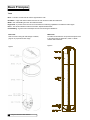
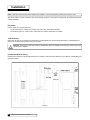
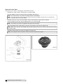
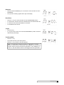
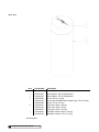
Brine Tank
Media Tank
Refer to section "Filling the Salt Storage Container",
page 21 for proper Brine Tank usage.
The letters underneath the component's description refer
to the values listed on Appendix A, Table 2 - Media
Volumes and Freeboard.
Figure 1
Figure 2
6
Culligan Gold Series™ Water Softener
What is Hard Water?
Water is said to be hard when it carries too high a concentration of calcium and magnesium. Acceptable water hardness
levels will vary depending on the application.
How Does it Work?
The components of dissolved minerals are called ions. They carry either a positive or negative charge. Hardness ions of
minerals dissolved in water carry a positive charge. These positively charged ions (cations) are attracted to a synthetic
softening material called ion exchange resin.
The heart of the softening system, therefore, is a deep bed of resin which draws calcium and magnesium ions, as well as
ferrous iron, from the water as it passes through the resin bed.
Can the Resin Draw Out Hardness Ions Indefinitely?
No. During normal operation, the resin becomes saturated with positive ions and functions less efficiently. When hardness
leakage occurs, the resin should be regenerated to restore its efficiency.
How Do You Regenerate Resin?
You regenerate a resin bed by removing the mineral ions through a process called "ion exchange". This regeneration
process occurs in four steps and takes approximately 50 to 70 minutes. Each of the following steps are graphically depicted
on pages 8 - 12.
1.
Backwash - During the backwash step, raw water flows rapidly upward (in reverse direction to the service flow) through
the resin bed to expand the bed and flush out accumulated dirt, sediment and other sources of turbidity.
2.
Brine Draw - The brine solution consisting of water and salt is drawn from a brine storage tank and allowed to flow
slowly down through the resin bed. The brine solution removes the calcium and magnesium ions from the resin.
3.
Slow Rinse - Brine draw is then followed by a raw water slow rinse. This rinse step will slowly remove most of the
remaining brine, exchanged calcium and magnesium ions from the resin.
4.
Fast Rinse - Slow rinse is followed by a raw water flush, a very rapid down flow of raw water which removes the last
traces of brine, and settles the resin bed.
How Often Must You Regenerate?
Frequency must be determined for each installation based on the amount of water usage, its degree of hardness and the
amount of resin through which it flows. In some cases it is necessary to utilize a resin cleaner when the raw water contains
iron. Contact your local Culligan dealer for more information.
How Do You Control the Regeneration Process?
The regeneration process for the water softener is controlled automatically either on a predetermined time, volume, or
external signal basis through the use of the Culligan Accusoft Plus controller with optional Aqua-Sensor® or flow sensor. The
regeneration process can also be initiated manually by the operator as required.
Basic Principals
7
Flow Diagrams
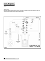
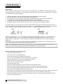
Service
Refer to Figure 3
Raw water is allowed in the inlet to the top of the tank. The water is run through the resin up the manifold to the outlet. The
water to the outlet should be soft if the system is operating properly.
Figure 3
8
Culligan Gold Series™ Water Softener
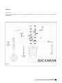
Backwash
Refer to Fig. 4
Raw water is directed down the center of the manifold, up through the resin, out the top of the tank to drain. The water to drain
should be hard.
Figure 4
Flow Diagrams
9
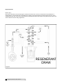
Regenerant Draw
Refer to Fig. 5
Raw water is directed from the inlet through the nozzle and into the throat. A vacuum is created and concentrated brine is
educted (drawn). The raw water and concentrated brine combine, enter the mineral tank, and pass through the resin, up the
manifold and to the drain. Once all of the brine has been educted and the brine valve seats, the unit goes into slow rinse. Hard
water is allowed to service during regeneration.
Figure 5
10
Culligan Gold Series™ Water Softener
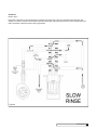
Slow Rinse
Refer to Fig. 6
Raw water is directed from the inlet through the nozzle and into the throat. A vacuum is created but the brine valve has
seated, so no brine is educted. The raw water enters the mineral tank, passes through the resin, up the manifold and to the
drain. Hard water is allowed to service during regeneration.
Figure 6
Flow Diagrams
11
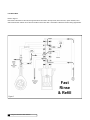
Fast Rinse/Refill
Refer to Figure 7
Raw water is directed from the inlet, through the eductor and inlet to the top of tank, down the resin, up the manifold, out to
drain and brine line until the correct amount of water is in the brine tank. Hard water is allowed to service during regeneration.
Fast
Rinse
& Refill
Figure 7
12
Culligan Gold Series™ Water Softener
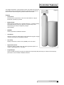
Controller Features
The Culligan Gold Series™ control's primary function is to initiate and control the
regeneration process via methods that are most convenient and cost effective
for the customer while offering many operation features and benefits.
Figure 8
Features
•
Power Source
Electrical power required for the control is 24-VAC 50/60 Hz. A plug-in
transformer (120v/24v) is provided
•
Battery Backup
Battery backup is available as an optional field add-on. The battery backup
will maintain the time of day for a minimum of 4 weeks using a 3.6V
1/2AA-lithium type battery as supplied by Culligan
(PN 01013839).
•
EEPROM
Saves programmed and statistical functions.
•
Lock/Unlock
Allows the control to be easily locked out from inadvertent program changes
or abuse. This feature can be disabled if desired.
•
Time of Day
Displays current time in either 12 hour (AM/PM) or 24 hour format.
•
Regeneration Interval
Provides an ability to initiate a time clock back-up operated system on a
number of days (range from 1 to 99 days).
•
Program Beeper
Emits an audible beep when key pads are depressed to help identify valid (short beep) or invalid (3 short beeps) key
pad touches. Can be enabled or disabled as desired.
Controller Features
13
Operation
Modes of Operation
Water Meter Mode
In water meter mode, the controller keeps track of the quantity of water that has flowed through the resin bed. Based on the
influent water hardness and the hardness capacity of the resin bed, a service life expectancy in the quantity of softened
water is calculated and programmed into the control. When the set point is reached, regeneration is triggered. In delay
regeneration mode, if the predict mode is turned on, the average daily water usage will be compared to the remaining
capacity at the regeneration delay time to predict if another day's water usage can occur before requiring regeneration. If
enough capacity is not present then the regeneration will occur at that time. If the predict mode is not selected, the
regeneration will start at time of regeneration. If time clock backup is set and the capacity has not been exhausted, the
softener will regenerate when days since last regeneration equal time clock back up. In immediate mode the regeneration
starts when the capacity is exhausted..
Aqua-Sensor® Mode
The Aqua-Sensor® is a conductivity probe that senses when a hardness front passes through the resin bed. It functions
independently of the influent water hardness so therefore, is useful in conditions when the influent water hardness varies
throughout the year. It provides for the most efficient mode of operation. In addition to sensing when a resin bed is
exhausted, it can also be used to determine when the brine solution is rinsed from the resin bed during the Brine Draw /
Slow Rinse cycle triggering the control to move to fast rinse. This patented feature provides water savings by optimizing the
amount of rinse water required to completely rinse out the resin bed.
Time Clock Backup Mode
This setting is used as a backup feature for either the meter or Aqua-Sensor® modes of regeneration. It provides
regeneration when a set period of time has elapsed. If the meter or Aqua-Sensor® does not trigger regeneration prior to the
time clock backup value, the time clock backup will trigger the regeneration.
Manual Regeneration
Pressing and holding the regen button for 3 seconds will initiate regeneration. The beeper is to give one beep at the start of
manual regeneration (cam starts to turn). In delay mode, pressing and releasing the regen button will light the regen icon for
regeneration to occur at the set delay time. Pressing and releasing the regen button again will turn off the regen icon. This
function is active in the Service mode and Diagnostic mode. In the diagnostic mode, toggling the + key will advance to the
next valve position while the regeneration is in process until home is reached. The statistics will not be updated if the last
cycle of regeneration does not automatically complete (The "+" key is pressed to cycle the control to the next position).
Predict Mode
The Predict Mode is used in the flow meter mode to determine the optimum regeneration point. Before the regeneration
starts, the control will compare the remaining capacity value with the average daily water use. If the average daily water
usage is less than the remaining capacity, the controller will wait 24 more hours before regeneration. If the remaining
capacity is less than the average daily water usage, the control will initiate regeneration. This works in delay mode only. At
any time, if the total capacity value is reached, the control will initiate an immediate regeneration.
14
Culligan Gold Series™ Water Softener
Efficiency Mode
Water softeners historically use an optimum time range to control the Regeneration cycle steps with a minimum and
maximum time required to perform each step dependent on the salt being used, the hardness total and iron level. Culligan
typically uses the maximum time range to ensure effective Regeneration. However, if the iron content of the water to be
softened is zero, and the hardness level is less than 20 gpg, Culligan has developed a new set of regeneration times geared
to reducing salt and water usage. These times are defined under a new operating mode coined "Efficiency Mode" (Not
available if DIP switches #6 or #9 are on). Compared to the present time values used, these new regeneration times and
salt dosages are considerably less. When in Efficiency mode, the control will refill for a higher salt dosage once every 10
regenerations according to tank size as shown in the following table.
Tank Sizes
Salt Dosages (lbs)
9x48
10
10x54
15
12x52
20
14x65
30
Pre-Rinse Mode
The Pre-rinse mode is used in the Time Clock, Flow Meter, and Aqua Sensor® softener modes, as well as in Flow Meter
Filter mode, to pre-rinse the softener resin bed or filter media DIP switch 9 must be set to "on". The pre-rinse in flow meter
mode will occur after the control has sensed that no water has flowed through the control for a period of X hours (can be set
through the programming menu). When the control is in this mode, once the X amount of hours have elapsed the control will
cycle to the fast rinse position for the pre-set length of minutes and then return to the home or service position. For Time
Clock or Aqua Sensor® modes the pre-rinse will occur at a fixed time then return to the home or service position.
Note: Be sure to set the brine safety level float to the proper position when using this mode since the refill step also occurs
in the fast rinse position. failure to do so will result in a higher salt dosage than anticipated.
Operation
15
Installation
Note: Read this section entirely before starting the installation. Follow all applicable plumbing and electrical codes.
With the exception of media containers, open the remaining containers, remove all the components, and inspect them before
starting installation.
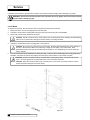
Placement
Refer to figure 9 for system placement.
•
Set the media tank on a solid, level surface near water, drain and electrical facilities.
•
Set the brine system on a flat, smooth, solid surface as near the media tank as possible.
Tank Assembly
Before the unit can be connected to the plumbing the manifold distributors must be assembled and the underbedding and
resin must be loaded into the tank for 12” and 14” tanks.
CAUTION! Do not lay the tank down unless a suitable lifting device is available. Personal injury and damage to the
unit can result if dropped.
Position the Mineral Tank(s)
Determine the location for the mineral tanks(s) prior to loading, since they will be difficult to move after the underbedding and
gravel are loaded.
Figure 9
16
Culligan Gold Series™ Water Softener
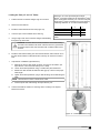
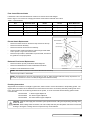
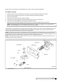
Loading the Tank (12” and 14” Tanks)
1.
Position the tank so that the Culligan® logo is in the front.
2.
Remove the inlet strainer.
3.
Install the outlet manifold into the tank (Figure 10).
4.
Cover the tops of the manifolds with a clean rag.
5.
Using a large-mouth funnel, load the Culligan underbedding
through the top of the tank.
Dimension “X” is the exposed length the AquaSensor® cord (cord length from the Aqua-Sensor® plug
to the circuit board connector). You can then verify the
Aqua-Sensor® probe is inserted to the proper depth by
confirming dimension “X” is at the corrected length.
9” Quadra-Hull™ Tank
10” Quadra-Hull™ Tank
12” Quadra-Hull™ Tank
14” Quadra-Hull™ Tank
X
34 1/2”
30 1/2”
32 1/2”
22 1/2”
Y
40”
44”
42”
52”
Table 1
CAUTION! DO NOT allow the outlet manifold to move when loading
the media. The manifold must remain vertical to ensure a good seal at
the gasket. Rap the tank near the bottom with a rubber mallet to level
the sand.
6.
Install the inlet strainer making sure to thread the strainer until it bottoms out on
the tank thread. Failure to install the strainer correctly can cause the control to
leak.
7.
Aqua-Sensor® Installation (optional device)
A.
Measure the sensor cable length as shown in Figure 10 and Table 1 (the
Aqua-Sensor® cord is set at the factory for a 9” tank).
B.
Loosen the small Aqua-Sensor® Plug, a needle-nose pliers works best.
C.
Moisten the cable sheath and slide the cable grip up or down to the proper
cable length.
D.
Tighten the small Aqua-Sensor® plug so that the fitting cannot slide along the
cable.
NOTE: There must be no kinks or bends in the cable.
E.
8.
Insert the probe and cable through the Aqua-Sensor® port.
Load the tank with the Cullex® ion exchange resin. Leveling is not required.
Remove the funnel.
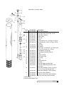
Figure 10
Figure 11 – Small Aqua-Sensor® Plug
Installation
17
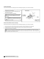
Mount the Control Valve
See Figure 12 for a visual on mounting the control valve to the tank.
•
Assemble the o-rings, located in the parts pack, to the tank adapter.
•
The valve adapter o-ring sits on the first step on the adapter. See Figure 13.
NOTE: Do not push the top o-ring down to the flange surface on the adapter.
NOTE: The larger of the two o-rings in the parts part goes between the adapter and the valve, do not stretch the
smaller o-ring onto the top of the tank adapter.
•
Lubricate only the top o-ring on the tank adapter, and the outlet manifold o-ring with silicone lubricant.
•
Screw the adapter into the tank until the adapter bottoms out on the tank flange.
NOTE: The adapter only needs to be tightened hand-tight to the tank flange.
•
Align the manifold with the center opening in the valve, and press the valve onto the adapter firmly.
NOTE: Make sure to push the valve straight down onto the manifold. If the valve is cocked, it may cause the o-ring to
slip off the manifold.
•
Assemble the tank clamp to the control, and tighten the clamp screw.
NOTE: The clamp and valve will be able to rotate on the tank until pressure is applied.
Figure 13
Figure 12
18
Culligan Gold Series™ Water Softener
Flow Control Eductor Nozzle
Listed below is the recommended eductor nozzle to be used at various salt dosages.
Refer to Figure 14 for a visual on changing the eductor nozzle and the backwash flow control.
Table 2 - Flow Restrictors
Unit
Backwash Flow
Nozzle
Throat
Brine Refill Flow
9”
2.0 gpm (#2 Brown)
Blue*
Light Brown*
0.45 gpm
10”
2.0 gpm (#2 Brown)
Beige
Light Brown
0.45 gpm
12”
3.5 gpm (#3 Green)
Beige
Light Brown
0.8 gpm
14”
5.5 gpm (Black)
Green
Blue
0.8 gpm
* Standard from factory
Eductor Nozzle Replacement:
•
Remove the three screws on the eductor cap and remove the cap.
•
Remove the eductor assembly.
•
Remove the eductor screen from the assembly
•
Remove the blue nozzle and replace it with the beige nozzle. Make
sure to put the o-ring on the correct nozzle.
•
Reverse the procedure to reassemble. To prevent leaks, ensure that
the gasket is in the proper position.
Backwash Flow Control Replacement:
•
Remove the drain clip and pull the drain elbow straight off.
•
Remove the backwash flow control located behind the elbow.
•
Install the correct backwash flow control.
Figure 14
NOTE: The number on the flow control should face into the valve body.
•
Reverse the procedure to reassemble.
NOTE: Dip switch #5 is to be in the “off” position for 9” and 10” Tanks (0.45 gpm refill flow control). Dip switch 5 is to
be in the “on” position for 12” and 14” tanks (0.80 gpm brine refill flow control).
Plumbing Connections
Shipped with each softener is a Culligan® bypass valve, which is used to connect the softener to the plumbing system. The
bypass allows the softener to be isolated from the water service line if service is necessary while still providing water to the
home. The bypass valve can be directly plumbed into the system, or can be connected with the following optional sweat
connection kits;
P/N 01010783
1" Sweat Copper Adapter Kit
P/N 01016564
3/4" Sweat Copper Adapter Kit
P/N 01016565
3/4" Elbow Sweat Copper Adapter Kit
CAUTION! Close the inlet supply line and relieve system pressure before cutting into the plumbing! Flooding could
result if not done!
CAUTION! When making sweat connections, use care to keep heat away from the plastic nuts used to connect the
plumbing to the bypass. Damage to these components may result otherwise.
Installation
19
Bypass Valve Installation
The bypass valve connects directly to the control valve with
a pair of couplings and two assembly pins (Figure 15).
Lubricate all o-rings on the couplings with silicone lubricant.
On Soft-Minder® meter controls, the meter replaces the
coupling on the outlet side of the control. The meter body
fits in the same space as the coupling between the control
valve and the bypass. Make sure that the arrow on the flow
meter is pointing in the direction of flow (Figure 15).
NOTE: The bypass stem can only be removed from
valve on the bypass side (red knob). The bypass valve
is designed so that it can be flipped over, with the bypass
(red) knob on the left side of the valve. This will need to
be taken into consideration if the control is plumbed in
close to a wall which may prevent the stem from being
easily removed.
Figure 15
The bypass valve has knobs that easily snap on and off of the stem. A screwdriver can be used to depress the snap lever
on the stem for knob removal. The knobs have alignment tabs that mate into the notches in the bypass body to ensure that
the stem is properly aligned in the bypass body. The service knob (blue) has a locking feature, which must be depressed in
order to shift the stem out of the bypass position (Figure 16).
NOTE: If the ground from the electrical panel or breaker box to the water meter or underground copper pipe is tied to the
copper water lines and these lines are cut during installation of the bypass valve, an approved grounding strap must be
used between the two lines that have been cut in order to maintain continuity. The length of the grounding strap will depend
upon the number of units being installed. In all cases where metal pipe was originally used and is later interrupted by the
bypass valve to maintain proper metallic pipe bonding, an approved ground clamp c/w not less than #6 copper conductor
must be used for continuity. Check your local electrical code for the correct clamp and cable size.
Figure 16
Drain Line Connection
Refer to Table 3, under the applicable tank size for drain line length and height limitations.
•
Remove 1/2” pipe clamp from the small parts pack included with the control.
•
Route a length of 1/2” drain line from the drain elbow to the drain.
•
Fasten the drain line to the elbow with the clamp.
•
Secure the drain line to prevent its movement during regeneration. When discharging into a sink, or open floor drain, a
loop in the end of the tube will keep it filled with water and will reduce splashing at the beginning of each regeneration.
NOTE: Waste connections or drain outlets shall be designed and constructed to provide for connection to the sanitary
waste system through an air gap of 2 pipe diameters or 1 inch, whichever is larger.
NOTE: Observe all plumbing codes. Most codes require an anti-siphon device or air gap at the discharge point. The
system and installation must comply with state and local laws and regulations.
20
Culligan Gold Series™ Water Softener
Operating
Pressure
30 psi (210 kPa)
40 psi (279 kPa)
50 psi (349 kPa)
60 psi (419 kPa)
80 psi (559 kPa)
100 psi (699 kPa)
Height of Discharge Above Floor Level Operating
0 ft
2 ft
4 ft
6 ft
8 ft
(0 m)
(0.6 m)
(1.2 m)
(1.8 m)
(2.4 m)
60 ft (18 m) 50 ft (15 m)
30 ft (9 m)
15 ft (5 m) Not allowable
100 ft (30 m) 90 ft (27 m) 70 ft (21 m) 50 ft (15 m)
30 ft (9 m)
145 ft (41 m) 115 ft (35 m) 80 ft (24 m) 80 ft (24 m) 60 ft (18 m)
100 ft (30 m) 100 ft (30 m) 85 ft (26 m)
Normal installation should not require
140 ft (43 m)
more than 100 ft (30 m) of drain line
10 ft
(3 m)
Not allowable
12 ft (4 m)
40 ft (12 m)
60 ft (18 m)
120 ft (37 m)
150 ft (46 m)
Table 3
Fill The Salt Storage Container
Fill the salt storage container with water until the level reaches about 1 inch above the salt support
plate. Pour salt into the container. Fill with salt to within a few inches of the top.
Brine Valve "A" Dimension
The Culligan Gold Series™ unit contains a brine float which can serve as a backup refill shutoff in the
event of a failure, such as a power outage when in the refill position. The float level should be set
based on the salt dosage setting. Refer to Figure 16B.
•
Lift the brine valve from the brine chamber.
•
Find the correct “A” dimension from Appendix A, Table 5.
•
Set the distance from the top of the filter screen to the base of the float accordingly. The slight
difference in height when the float is pulled up or down is negligible.
Figure 16B
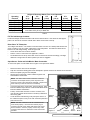
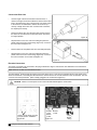
Aqua-Sensor® Probe and Soft-Minder® Meter Connection
To connect the probe or meter leads refer to Figure 21 and proceed as follows:
•
Remove the timer case from the back plate.
•
Snap the circuit board holding plate off the back plate to provide access to the back of the circuit board.
•
Remove the plastic plug from the backplate.
•
Slip the sensor probe lead or meter cable through the hole
and toward the circuit board.
NOTE: The strain relief located on the back of the wire
connection for the Aqua-Sensor® probe may have to be
removed in order to fit it through the backplate. Replace the
strain relief if you need to remove it for assembly.
•
Connect the lead to the circuit board. The Aqua-Sensor® probe
terminal is labeled "Aqua-Sensor®" while the Soft-Minder meter
terminal is labeled "Flow Meter".
•
Pull any excess cable wire back out of the enclosure, and
route the wiring inside the enclosure to avoid any interference
with moving parts.
•
Locate the strain relief bushing in the parts pack. Place it on
the cable at the point of entry to the rear of the timer plate and
push it into the hole.
NOTE: The wire connectors must be connected to the
circuit board properly. The wires must exit the plug-in
connector opposite of the raised white base of the circuit
board connector. Failure to properly connect any of the
connectors will result in a malfunction of the circuit board
operation.
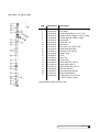
Dip
Switches
Optional
Battery
Power
Figure 17
Motor
Cam
Switches
Soft®
Aqua- Minder
®
Meter
Sensor
Installation
21
Connect the Brine Line
•
Use the length of brine line included in the brine tank, or
measure a length of brine line sufficient to reach from the brine
tank to the brine fitting, with no sharp bends. For easier access
to the float it is recommended to add an extra four feet (1.3
meters) of length to the brine line. Cut both ends of the brine
line squarely and cleanly.
•
Remove the brine valve from the brine tank and then remove
the white nut and insert from the float rod. Return float rod to
its original position.
•
Slip the white nut over one end of the tubing and press the
plastic insert into the end of the tubing (Figure 18). Connect to
the brine valve and tighten nut.
•
Remove white nut and plastic insert from the small parts pack.
•
Slip the white nut over one end of the tubing and press the
plastic insert into the end of the tubing (Figure 18). Connect to
the brine connection on the valve and tighten nut.
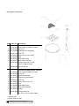
Figure 18
Figure 19
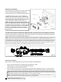
Electrical Connection
The power cord needs to be connected to the plug-in transformer. Figure 19 shows the cord attachment to the transformer
for non Aqua-Sensor® models.
Note: Observe all state and local electrical codes.
The Aqua-Sensor® probe (Figure 20) requires a 2.5 VAC power source. This source is provided via two of the posts on the
24V/2.5V transformer. Two leads from the transformer must be wired to the 2.5 VAC terminal on the circuit board. The wire
connector from the Aqua-Sensor® probe is simply plugged in the circuit board (Figure 21).
CAUTION! Failure to connect power to the correct terminals will damage the circuit board!
Power to circuit board, 2.5 VAC
for Aqua-Sensor® installation
Figure 20
22
Culligan Gold Series™ Water Softener
2.5 VAC
AquaSensor®
Power
Figure 21
24 VAC
Power
AquaSensor®
Wiring
Programming
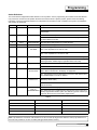
Switch Definitions
The circuit board is shipped with all DIP switches in the off position. Prior to programming the controller some DIP switches
may need to be moved to the ON position. Because each switch serves a specific purpose, please review the following
information, moving the required switches to an ON position as necessary for each controller in the system. The definitions
and purpose are as follows:
Switch #
Abbreviation
Definition
1
R/T
Run/Test
Purpose
Off- Allows controller to function in a normal, operational mode.
On - Places controller in test mode to verify operation of the board
components.
2
SO/FI
Softener/Filter
Off - The unit shall be operated as a softener.
On - The unit shall function as a filter. The default time programmed for
cycle #2 shall be 2 minutes.
3
CTLR
Control Selection
See DIP switch settings below for control selection.
4
CTLR
Control Selection
See DIP switch settings below for control selection.
5
S/F
Standard Refill/
Fast Refill
Off - The 0.45 gpm refill flow control is used to control the refill flow rate.
Set in the off position for 9" and 10" units.
On - The 0.80 gpm refill flow control is used to control the refill flow rate.
Set in the on position for 12" and 14" units.
6
D/I
Demand/Immediate Off - Regeneration of a unit will occur at a user-selected time of day.
On - Regeneration shall occur immediately upon a controller receiving a
valid regeneration initiation signal, regardless of the time of day.
7
E/M
English/Metric
Off - The unit will function in standard English dimensions.
On - The unit will function in standard metric dimensions.
8
12/24
12 Hour Clock/
24 Hour Clock
Off - All time keeping functions shall be based on an AM/PM basis. The
AM or PM icon shall be lit in the display as appropriate.
On - Time keeping functions shall work on a 24-hour clock (military time).
The AM/PM display icons will be disabled.
9
–/ADV
Advance Off/
Advance On
Off - The Predict Mode and Pre-Rinse Mode will not be activated.
(Efficiency will be active)
On - The Predict Mode and Pre-Rinse Mode will be activated. (Efficiency
will not be active)
10
–/TCB
Time Clock
Back-up
Disabled/Enabled
Off - The time clock backup option is not enabled.
On - Allows the user to enable the time clock function of the control as a
backup regeneration initiation option. This feature is used as a back up to
a primary device such as a flow meter, Aqua-Sensor®.
Table 4
Dip #3
Dip #4
Control
Off
Off
Gold
On
Off
Platinum
Off
On
Other
On
On
Other
Table 5
Note: Dip Switch 5 is to be in the “Off” Position for 9” and 10” tanks (0.45 gpm brine refill flow control). Dip Switch 5 is to
be in the “On” position for 12” and 14” tanks (0.80 gpm brine refill flow control).
Programming
23
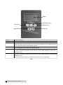
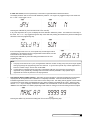
Display
Regeneration Key
Status Key
Statistics Key
Toggle Up
Toggle Down
Display
Status Key
Regeneration Key
Statistics Key
Toggle Down Key
Toggle Up Key
Back lit LCD display.
Depress to enter and move through the programming steps.
Press and hold the key for three (3) seconds to initiate an immediate regeneration.
When pressed during programming the time of day, this key will allow the user to toggle between the
hours and minutes setting of timing program segments.
Each time depressed, the Statistics key will display statistical information such a flow rate, time of day. Use
with the Toggle Down key to display other statistical information.
In the programming mode this key will move the user through the programming function in a descending mode. If depressed for greater than three seconds, the rate at which the display scrolls through
data will increase.
In the programming mode this key will move the user through the programming function in an ascending mode. If depressed for greater than three seconds, the rate at which the display scrolls through the
data will increase.
This key will also allow the user to manually step through the cycles of regeneration.
Table 6
24
Culligan Gold Series™ Water Softener
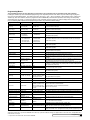
Programming Menus
The programming menus will vary depending on which devices are connected to the circuit board and dip switch settings.
Pressing the "Status" key enters the standard programming mode. Repeated presses of the "Status" key will scroll through the programming menu to each desired setting. The value is then set by using the "+" and "-" keys to increment or decrement the value. Pressing the
"Status" key, after value selection, saves the programmed value to EEPROM (unless otherwise specified; some settings are temporarily
stored before they are saved). To exit the programming mode, repeatedly press the "Status" key until the display returns to time of day display. The following table outlines all of the programming functions, range limits and default settings:
Setting
* Beeper
Range Limits
Toggle (Y / N)
Default
Y
Comments
Enable/disable the key press beeper (ERR/Alarm Code beeps can't be disabled)
Time of Day
12:00AM-11:59PM(12hr)
00:00-23:59 (24hr)
12:00 PM 12:00
12 / 24 hour function set with dip#8
* Time of Regen
12:00AM-11:30PM(12hr)
00:00-23:30 (24hr)
2:00 AM 02:00
Adjustable in 30 minute increments only
* Regen Interval
Days - 1 to 99 days
3 days
Displayed in Time Clock Mode (displayed in Flow Meter and A/S If dip#10 on)
*‡ Hardness Type
S - Standard Metric,
F - French Metric,
D - German Metric
S - Standard Metric
Only active with flow meter if dips#3&4 are set to Gold or Platinum and dip#7 is set to 'metric'
(Not available in Filter operation)
*‡ Hardness
1 - 110
1 - 110
2 - 189
1 - 105
25 - English
25 - Standard Metric
43 - Metric French
24 - Metric German
Only displayed if DIP Switch 3 & 4 are set to Gold or Platinum and flow meter attached (Not
available in Filter operation)
*‡ Iron
0-5
0
Only displayed if DIP Switch 3 & 4 are set to Gold or Platinum and flow meter attached (Not
available in Filter operation)
*‡ Salt Type
KCl or NaCl
NaCl
Only displayed if DIP Switch 3 & 4 are set to Gold or Platinum and flow meter attached (Not
available in Filter operation)
*Predict Mode
Yes or No
No
Only Active if DIP Switch 9 is on and DIP Switch 6 is off and a flow meter is connected to the
control (Not available in Filter operation)
*Pre-Rinse Mode
Yes or No
No
Only active if DIP Switch 9 is on.
*Pre-Rinse Duration
01 - 15
05
Only active if DIP Switch 9 is on and the Pre-Rinse mode is set to 'Yes'.
*Pre-Rinse Hours
1 - 240
24
Only active if Dip Switch 9 is on and Pre-rinse mode set to yes and a flow meter is connected to
the control
*Pre-Rinse Time of Day
12:00AM-11:30PM(12hr)
00:00-23:30 (24hr)
5:00 AM 05:00
Only active if Dip Switch 9 is on and Pre-rinse set to 'yes'; Adjustable in 30 minute increments
only; Available only in TimeClock and Aqua-Sensor® mode (not meter mode)
*‡ Efficiency Mode
Yes or No
No
Available only if DIP Switch 3 & 4 are set to Gold or Platinum with flow meter connected; Iron =
0; Hardness <= 20 (English hardness units) "Efficiency Mode" icon lit when enabled (Not available if dips#6or9 on, or Filter mode)
*‡ Gold Tank Size
9x48, 10x54, 12x52, 14x65
9x48
*‡ Platinum Tank Size
10x54, 12x52, 14x65, 16x65
10x54
*‡ Defaults
Yes or No
Yes
Only displayed if DIP Switch 3&4 are set to Gold or Platinum and a flow meter is connected.
(Not available in Filter operation)
View
Y or N
N
Only displayed if "Defaults" was set to "YES"
*Salt Dosage
3 - 60 Lbs 0.5 - 27.5 kg
Timeclock/ Aqua-Sensor®:
7Lb/3.0kg; Flowmeter: default
varies based on tank size
If DIP Switch 3 & 4 are set to Gold or Platinum (Not Available if DIP Switch 3 & 4 are set to
other.) (Not available in Filter operation)
* Meter "K" Factor
0.5 - 500
50.0
Only displayed with Flow meter connected and DIP Switches 3 & 4 on (other).
* Cycle 1 time
1 to 99 minutes
10min (5min efficiency mode)
* Cycle 2 time
1 to 99 minutes
Softener mode-TC mode or
dips#3&4 set to other-60 mins; -Softener / Filter function set with DIP switch #2
Flow meter-lookup table; A/S
-For Gold or Platinum: cycle time default is loaded from table;
mode-99 minutes Filter mode - -flow meter must be connected
2 minutes
* Cycle 3 time
1 to 99 minutes
English
Standard Metric
Metric French
Metric German
Only displayed if DIP Switch 3&4 are set to Gold or Platinum, respectively and a flow meter is
connected (Not available in Filter operation)
10 minutes
Only displayed if DIP Switch 3 & 4 are set to Platinum or Other.
* Cycle 4 time (if 5 cycle valve) 1 to 99 minutes
10 minutes Filter-2 minutes
Only displayed if DIP Switch 3 & 4 are set to Platinum or Other(with 5 cycle valve detected)
*** Day(s) of Week Regen
'dAYoWK' Yes or No
Scroll days of the week,
Toggle Y/N
No
Time Clock Mode Only; Active for softener and filter
SUN N
Only active if 'dAYoWK' was set to 'Yes'
*** Current day of week
Scroll days of the week
SUN
Only active if at least one day of the week was 'Y' in 'Regen Day(s)' above
* Total Capacity Set Point
(MaxCap)
999,999 (other or filter);
1 - 999,999 (can't be set less
-Set point to trigger immediate regen -Only active with flow meter connected -(For Filter operaCalculated for (Gold or Platinum
than BATCH)
tion, see filter media life feature description)
softeners)
*Filter Media Life
Toggle (Y or N)
N
* Batch Capacity
1 - 999,999 (can't be set
greater than MaxCap)
870 (other or Filter); Calculated -Only active with flow meter connected -For Gold or Platinum, the value shown is calculated by
for (Gold or Platinum softeners) control; value may be overridden by user by setting 'defaults' to 'no'
* Lock / Unlock
Toggle Lock & Unlock
Unlock
***Regeneration Day(s)
Enable/disable the filter media life feature (filter Operation ONLY)
-Lock or unlock access to program changes -Only accessible from service mode, time of day
display; press and hold '+' and '-' keys together for 5 seconds- (not while in programming menu)
*To be saved in EEPROM
‡Temporarily stored value; only saved to EEPROM when 'status' key is pressed at 'dEFLtS' setting. This applies ONLY to flow meter mode, with dips#3&4 set to
Gold, Platinum, or Europe.
*** only active in time clock mode; value saved in EEPROM.
Programming
25
Display Icons
The display is to be backlit and have the icons as shown below.
Custom LCD Display
Six standard 12-segment alpha-numeric characters, a decimal separating the first and
second character, a colon separating the second and third character positions, AM,
PM, REGEN, EFFICIENCY MODE, TODAY'S, AVG DAILY, WATER USAGE,
SOFTWATER, REMAINING, %, MINS, BACKWASH, BRINE RINSE, FAST RINSE, /,
REFILL, GALLONS, LITERS, FLOW RATE, GPM, LPM Icons
A further description of each programming setting and the corresponding display is outlined below. For a display that has an
icon that is displayed solid for the 2 second time period prior to bringing up the settings, the settings menu can be reached
prior to the two second time out by pressing the "+" or "-" key.
•
Beeper Setting - This setting is used to turn the beeper on or off for each key
press actuation. The display will show "bEEP X" where X is either "Y" or "N".
The "Y" or "N" will be toggled with the "+" and "-" keys. Setting the Beep option
to "N" will only disable the beeper for key press actuation. The beeper will still
be active for error and alarm codes.
Pressing the "Status" key will save the setting and move to the next
programming step.
•
Time of Day - This setting is used to program the current time of day. When in
this step the display will first show "tod" for two seconds.
After "tod" is displayed, "12:00 PM" will display (or the current set time if already
programmed) and the minutes will flash. The minutes are adjusted with the "+"
or "-" key until the correct value is displayed.
Press the "Regen" key to flash the hours. Adjust with the "+" or "-" key until the
correct time is displayed.
Pressing the "Status" key will save setting and move to the next programming step. Pressing "Regen" will move back to
the minutes adjust.
•
Time of Regeneration - This setting is used to program the time at which a
regeneration is to occur in the delay mode, or in immediate mode with time
clock backup on. The display will first show "tor" for two seconds.
After "tor" is shown the display will then show the default of 2:00 AM (or the
current programmed time of regeneration if already set). The time can be
adjusted in 30 minute increments by pressing the "+" or "-" keys.
Pressing the "Status" key will save the setting and move to the next
programming step.
26
Culligan Gold Series™ Water Softener
•
Regeneration Interval - This setting is used to set the days between
regeneration in time clock mode. It is also active in meter or Aqua-Sensor®
mode if the time clock backup DIP switch # 10 is set to on. The display will
show "REGEN" icon and "dAYS" as well as the numbers to change. Adjust the
value with the "+" or "-" keys.
Pressing the "Status" key will save the setting and move to the next
programming step.
•
Hardness Setting (flow meter only) - This setting is used to set the hardness (grains) of the influent water supply. The
display will only appear if a flow meter is connected to the circuit board and the control is set to Gold or Platinum
(softener mode only). For English Units the display will first show "Hard" for two seconds and then display the Hardness
default (or the previously programmed value). Adjust the value with the "+" or "-" keys.
(These settings will not get saved to EEPROM until the 'status' key is pressed while at the 'dEFLtS' programming step)
•
Iron Setting (flow meter only) - This setting is used to set the iron level (PPM)
of the influent water supply. The display will show "Iron" in the left most digits
and the iron default setting (or the previously programmed value) in the far right
digit. The display will only appear if a flow meter is connected to the circuit
board and the control is set to Gold or Platinum (softener only). Adjust the
value with the "+" or "-" keys.
Pressing the "Status" key will temporarily store the setting and move to the next
programming step. (This setting will not get saved to EEPROM until the 'status'
key is pressed while at the 'dEFLtS' programming step)
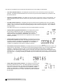
•
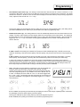
Salt Type (flow meter only) - This setting is used to select the regeneration salt type (softener mode only). This
display will only appear if dips#3&4 are set to Gold, Platinum, or Other. The display will show "SALt" for 2 seconds.
Then display the default 'NACL'. Pushing the "+" or "-" keys will change to 'KCL'.
NACL
KCL
Pressing the "Status" key will temporarily store the setting and move to the next programming step. (This setting will not
get saved to EEPROM until the 'status' key is pressed while at the 'dEFLtS' programming step)
•
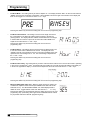
Predict Mode (flow meter only) - This setting will only be displayed if dip#9 is
on, dip#6 is off, and a flow meter is connected. Only available in softener
mode. The display will show "PRED" in the left most characters and toggle
between "Y" and "N" in the right most character with the "+" and "-" keys.
Pressing the "Status" key will save the setting and move to the next
programming step.
Programming
27
Programming
•
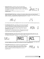
Pre-Rinse Mode - This setting will only be active if dip#9 is on. The display will show "PRE-" for two seconds and then
"RINSE" in the left most characters of the display. When "RINSE" is shown the right most character of the display will
flash "N" and toggle to "Y" with the use of the "+" or "-" keys.
PRE
RI NS E Y
Pressing the "Status" key will save the setting and move to the next programming step.
•
Pre-Rinse Time Duration - This setting is used to set the length of time that
the control will be in the fast rinse position before returning to the Service
(Home) position. The display will show "RINS" and XX where XX is the length
in minutes that the control is to pre-rinse as well as the "FAST RINSE" icon.
Adjust the XX value with the "+" and "-" keys.
Pressing the "Status" key will save the setting and move to the next
programming step.
•
Pre-Rinse Hours - This setting will only be active if the Pre-Rinse mode is set
to 'Yes' and a flow meter is attached to the control. The display will show
"HOUR" in the left most characters and "XX" in the right most digits where "XX"
represents the hours setting from 01 - 99. The hours setting is adjusted with
the "+" and "-" keys.
Pressing the "Status" key will save the setting and move to the next
programming step.
•
Pre-Rinse Time of Day - This setting will only be active if the Pre-Rinse mode is set to 'Yes' and the control is operating
in time clock or Aqua-Sensor® mode. The Display will show "TIME" for 2 seconds and then the flashing time display as
in the time of regeneration display. The time can be adjusted in 30 minute increments with the "+" and "-" keys.
Pressing the "Status" key will save the setting and move to the next programming step.
•
Efficiency Mode (flow meter only) - Efficiency mode will only be active if the
conditions as explained earlier are met (Not available if DIP switch #6 or DIP
switch #9 are on). The "EFFICIENCY MODE" Icon will be displayed with a
default of "YES". Toggle between "YES" and "NO" with the "+"
or "-" key.
Pressing the "Status" key will temporarily store the setting and move to the next
programming step. (This setting will not get saved to EEPROM until the 'status'
key is pressed while at the 'dEFLtS' programming step)
28
Culligan Gold Series™ Water Softener
Programming
•
Gold Tank Sizes (flow meter only) - This setting is used to determine what size tank the control is connected to. It will
only appear if DIP Switch 3 & 4 are set to Gold, Platinum and a flow meter is connected to the circuit board. The display
will first show "GOLD" or "PLAtIN" for two seconds and then display the tank size default (or the previously programmed
value). Adjust the tank size with the "+" or "-" keys.
Pressing the "Status" key will temporarily store the setting and move to the next programming step. (This setting will not
get saved to EEPROM until the 'status' key is pressed while at the 'dEFLtS' programming step)
•
Defaults (flow meter only) - This setting allows the control to automatically determine what the values shall be for salt
dosage, cycle times, batch capacity, and total capacity based on the "temporarily stored" values above. The display will
first show "dEFLtS" for two seconds and then display "YES" or "NO", with "YES" being the default. "YES" and "NO" are
toggled with the "+" or "-" keys. This feature will only appear if dips#3&4 are set to GOLD or PLATINUM and a flow
meter is attached.
If 'YES' is chosen, then pressing the "STATUS" key will let the control automatically lookup, calculate, and save the
values for salt dosage, cycle times, batch capacity, and total capacity, and proceed to the next item in the programming
menu.
If 'NO' is chosen, then the programmer will have the ability to set each value as desired for salt dosage, cycle times,
batch capacity, and total capacity. (Choosing "NO" will cancel Efficiency Mode if it was active prior to this step)
In either case, pressing the "STATUS" key at this step will save into EEPROM the "temporarily stored" values of
hardness type (if metric), hardness, iron, salt type, and efficiency mode. These values are temporarily stored until this
point in the event of a programming mode timeout. If a timeout does occur before the 'dEFLtS' setting is saved, then
these "temporarily stored" values shall not change what was previously saved in EEPROM.
•
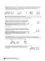
View - This setting is used to allow the programmer to view the calculated and
looked up values for salt dosage, cycle times, batch capacity, and total
capacity. These values may only be viewed and can't be changed at this time.
This 'View' programming item is only available in the menu if 'dEFLtS' was set
to 'YES'. The display will show "VIEW N". The "Y" or "N" will be toggled with
the "+" and "-" keys. The default for this item shall always be "N" and does not
get saved in EEPROM. The programmer must always toggle to "Y" in order to
view these items.
V IEW N
If "Y" is chosen, then pressing the "STATUS" key will display the value for salt dosage; repeated presses of the status
key will display cycle times, batch capacity, and total capacity.
Pressing the "STATUS" key after viewing "Maxcap" will exit the programming menu..
If "N" is chosen, then pressing the "STATUS" key will exit the programming menu.
Programming
29
•
Salt Dosage - This setting is used to set the salt dosage. It will only be accessible to be set if dips#3&4 are set to Gold
or Platinum and 'dEFLtS' was set to 'NO'. The display will first show "dOSAGE" for two seconds and then display the
default (or previously programmed value). The proper units (lbs or kg) will appear according to dip#7 setting
(English/Metric). Adjust the salt dosage with the "+" or "-" keys.
Note: This setting also appears during Aqua-Sensor® Programming.
Pressing the "STATUS" key will save the setting and move to the next programming step.
•
Cycle 1 Time - This setting is used to program the cycle 1 time that is usually
backwash. The time of the cycle is kept in minutes. The display will show the
"BACKWASH" and "MINS" icons and the cycle time in the right most digits.
Note: This setting also appears during Aqua-Sensor® Programming.
Adjust the value with the "+" or "-" keys.
Pressing the "Status" key will save the setting and move to the next
programming step.
•
Cycle 2 Time - This setting is used to set the time in minutes for cycle 2. This
cycle is brine draw / slow rinse for softeners. The display will show the "BRINE
RINSE" and "MINS" icons and the cycle time in the right most digits. Adjust the
value with the "+" or "-" keys.
Note: This setting also appears during Aqua-Sensor® Programming.
Pressing the "Status" key will save the setting and move to the next
programming step.
•
Day(s) of Week Regeneration - In the time clock mode only (Meter or Aqua-Sensor® not connected), the following
optional days of the week setting will be available to trigger regeneration. The display will show "dAYoWK" for 2
seconds followed by "NO". The "+" or "-" key will toggle "yes" or "no" (default is NO). A "yes" response will indicate that
the control is to perform a regeneration on specific days of the week.
Pressing "STATUS" will save and advance to the next step. If "NO" was
chosen, then the control will only initiate regenerations based upon the interval
(in number of days) and the display will show as shown in Regeneration
Interval above.
30
Culligan Gold Series™ Water Softener
If "YES" was chosen, then the specific days of the week to regenerate will be selected as follows:
The display will show "dAY" for two seconds followed by "SUN N". The "regen" key toggles the days of the week and
the "+" and "-" keys toggle "Y or N".
Pressing the "STATUS" key saves and advances to the next step.
If any of the days were set to "yes", the display will show "SETDAY" followed by "SUN". This selects the current day of
the week. The "+" or "-" key toggles through the days of the week and pressing the "STATUS" key saves the setting and
advances to the next programming step.
If ALL of the days were set to "no", then specific day of week regens will be
canceled and will appear as shown in Regeneration Interval above, and the
interval will be set in number of days.
Pressing the "STATUS" key saves the setting and advances to the next
programming step.
Note:
•
1.
If any day of the week is set to "yes", the regeneration interval in number of days ("Days 03") will no longer appear
when going through the programming menu at a later time. To go back from specific day of week regeneration to
interval in number of days, choose "NO" at "dAYoWK".
2.
If a DIP switch is changed anytime (other than run/test dip#1) after the control has been programmed to
regenerate on any specific day, all settings will revert back to default ("dAYoWK" = NO); specific days to
regenerate and current day will have to be reprogrammed.
Total Capacity Set Point (Max Capacity) - This setting is used to program a value that corresponds to the maximum
capacity that can be expected from a unit before it is completely exhausted. If the unit reaches this set point an
immediate regeneration will occur even if the control is set to delay mode. This setting will only appear if a flow meter is
connected to the circuit board and if dips#3&4 are set to Gold or Platinum with 'dEFLtS' set to 'NO'. Adjust the value
with the "+" or "-" keys. The display will show the "REGEN" icon and "MAXCAP" for two seconds and then display the
"REGEN" and "GALLONS" or "LITERS" (depending on DIP switch #7 setting) icons and the setting numbers to adjust.
Pressing the "Status" key will save the setting and move to the next programming step.
Programming
31
•
Batch Set Point - This setting is used to set the trip point for regeneration when in flow meter operation. It will only
appear if a flow meter is connected, dips#3&4 are set to Gold or Platinum with 'dEFLtS' set to 'NO', or dips#3&4 set to
'other'. The programmed setting displays the actual set point to trigger regeneration. The display will show the
"REGEN" icon and "CAP" for two seconds and then display the "REGEN" and "GALLONS" or "LITERS" (depending on
dip#7 setting) icons and the setting numbers to adjust. Adjust the value with the "+" or "-" keys.
Pressing the "Status" key will save the setting and exit the programming menu.
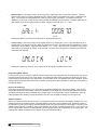
•
Screen Locking - The screen locking can be toggled off and on by pressing the "+" and "-" keys simultaneously for 5
seconds while in the regular time of day display in standard service mode. The display will show "UNLOCK" or "LOCK"
depending on the last setting. Toggle the screen with the "+" or "-" keys. When the screen is locked the only program
menus that can be changed are 'beeper', TOD, and TOR. The other menus will appear as normal but their values will
not be able to be changed.
Pressing the "Status" key will return to the regular time of day display in standard service mode.
Programming Mode Timeout
If no key activity occurs for a period of 180 seconds (3 minutes) while in programming mode, the mode will time out, exit the
programming mode and return to time of day display. Any setting that wasn't saved by pressing the 'status' key prior to the
control timing out will revert back to the original value. (For flow meter mode, with dips#3&4 set to Gold or Platinum, the few
settings that had temporarily stored values will revert back to their previous setting UNLESS the 'status' key was pressed at
the 'dEFLtS' display.)
Regen Time Remaining
Upon exiting the programming menu, the current time or day should be displayed on the servicing display. If the unit is in
regeneration while in the service display, pressing the “REGEN” key will display how much total regeneration time remains.
The display will stay active until the “REGEN” key is pressed again, or the regeneration ends (In Aqua-Sensor® mode, the
total regeneration time remaining includes the full brine rinse time, but will adjust accordingly upon auto rinse out).
Statistic Functions
While in the statistic functions all keys are active. The statistical functions are reached by pressing the "Statistics" key. The
statistics will have two operational modes; a standard statistics mode and a service statistics mode. Repetitive presses of
the "Statistics" key will cycle through the standard statistics mode until cycled back to time of day display. The service mode
statistics will be entered by an initial key press of the "Statistics" key and then successive presses of the "-" key. While in the
service mode statistics, the functions will repeatedly cycle through the menus until the "Statistics" key is pressed again. The
following table outlines the statistic function display, range limits and default setting:
32
Culligan Gold Series™ Water Softener
Statistics
Display
Time Clock (Standard Statistic)
Aqua Sensor (Standard Statistic)
Range Limits
N/A
N/A
Flow Rate (Standard Statistic)
0 to 999.0
* Capacity Remaining
(%)(Standard Statistic)
0 - 100%
* Capacity Remaining
(gal/L) (Service Statistic)
0 - 999,999
*Filter Media Life Remaining
(Service Statistic)
0 - 999,999
* Total Flow/Life Unit (Service Statistic)
*Today's Water Usage
*Avg. Daily Water Usage
* Number of Regens
- Last 14 days (Service Statistic)
1 - 999,999
0 - 9999
0 - 9999
0 to 99
* Number of days since last
Regen (Service Statistic)
* Number of Regens
- Life of the Unit (Service Statistic)
* Last slow rinse time
(Service Statistic)
0 to 99
0 to 999,999
0 to 99
Comments
Display alternates between 'time' and 'clock' every
second, until 'statistics' key is pressed or function
times out. Pressing and holding the 'REGEN' key for
10 sec while in this display can access Auto Test
Mode.
Display alternates between 'aqua' and 'sensor' every
second, until 'statistics' key is pressed or function
times out.
Based on "K" factor setting, updated a minimum of
every 6 seconds (Only active with Flow Meter
attached).
% of capacity remaining based on the batch set
point and the volume of water that has passed
through the flow meter (Only active with Flow Meter
attached)
Remaining gallons (liters) until capacity is reached
(valid for Service statistics when flow meter is
attached)
-ONLY active in filter mode with 'Life' option set to 'Y'.
-Remaining gallons (liters) until 'total flow for life of
unit' reaches the value of 'total capacity set point',
indicating the end of the filter media life
Only active with Flow Meter attached
Water usage from 12:00AM - 11:59PM
Average Daily Water Usage over the last 7 Days
-Days counter is to be updated at 12:00 AM ONLY
when dip#6 is on AND dip#10 is off; Otherwise,
update at whatever TOR is set for.
-Number of Regens is to be updated after regen is
complete
-Days counter is to be updated at 12:00 AM ONLY
when dip#6 is on AND dip#10 is off; Otherwise,
update at whatever TOR is set for.
-After a regen is complete, the counter is to be reset to 0
Counter is to be updated after completion of
regeneration cycle
Only active if Aqua-Sensor® is attached
* To be saved in EEPROM before the control is powered down during a power outage.
Statistics
33
Once either of the statistics menus is entered the information shown for each display is outlined below:
•
Time Clock (standard statistics) - This display will only show when in time clock mode (no meter or aqua sensor
attached). The display will alternate between 'time' and 'clock' every second until the 'statistics key' is pressed or until
the function times out.
•
Aqua Sensor (standard statistics) - This display will only show when in aqua sensor mode (no meter attached). The
display will alternate between 'aqua' and 'sensor' every second until the 'statistics' key is pressed or until the function
times out.
•
Flow Rate (standard statistics) - This display will only show if the flow meter is attached to the control. The display
shall show the current flow rate of the water passing through the control. The display will show the "FLOW RATE" and
"GPM" or "LPM" icons and the current flow rate passing through the flow meter for as long as the "-" key or "Statistics"
key is not pressed.
This display shall never time out, as opposed to the rest of standard statistics (10 minutes).
•
Capacity Remaining (%)(standard statistics) - This display will only show if
the flow meter is attached to the control. The display shows the percent
capacity remaining in the batch before regeneration will be triggered. The
display will show the "SOFTWATER", "REMAINING" and "%" icons for
softeners. This display shall never time out, as opposed to the rest of standard
statistics (10 minutes).
•
Capacity Remaining (gal/L) (service statistics) - This display will only show if
the flow meter is attached to the control. The display shows the gallons or liters
of capacity remaining in the batch before regeneration will be triggered. The
display will show the "SOFTWATER", "REMAINING", and "GALLONS" or
"LITERS" icons (depending on DIP Switch #7 setting) for softeners.
•
Total Flow/Life of Unit (service statistics) - This display will only show if the flow meter is attached to the control. The
display will show a flow totalizer. The total amount of flow that has passed through the unit since it was installed will be
maintained. The display will first show "totAL" for 2 seconds and then display the "GALLONS" or "LITERS" icon
(depending on dip#7 setting) and the totalizer value for 10 seconds. This 2 and 10 second cycle should repeat until the
"Statistics" key or "-" key is pressed, or the statistics time out brings the display back to time of day. If in filter mode with
'LIFE' option set to 'Y', pressing and holding the "REGEN" key for 10 seconds at the previous display will reset this value
back to zero.
•
Today's Water Usage (standard statistics) - This display will only show if the
flow meter is attached to the control. The display will show the accumulated
flow of water for the current day. The value is to start totaling at 12:00 AM and
reset to 0 at 11:59:59 PM. The display will show the "TODAY'S", "WATER
USAGE" and "GALLONS" or "LITERS" icons (depending on dip#7 setting) and
the total days flow based on the "K" factor and number of pulses received from
the flow meter.
34
Culligan Gold Series™ Water Softener
•
Average Daily Water Usage (standard statistics) - This display will only show
if the flow meter is attached to the control. The display will show a running 7day average of daily water usage. The display will show the "AVG DAILY",
"WATER USAGE" and "GALLONS" or "LITERS" (depending on dip#7 setting)
icons and the averaged flow value.
•
Number of Regenerations in Last 14 Days (service statistics) - This display will show the number of regenerations
that have occurred in the last 14 days. The display will first show "14dAY" for two seconds and then display the number
of regenerations that have occurred.
•
Number of Days since Last Regeneration (service statistics) This display shows the number of days that have elapsed since the last
regeneration. The display will show "DAYS XX" where XX is the number of
days that have elapsed since the unit completed its last regeneration.
•
Total Number of Regenerations for Life of Unit (service statistics) - This display will show the total number of
regenerations that have occurred since installation. The display will show "totALR" for two seconds and then display the
total number of regenerations.
•
Last Slow Rinse Time (service statistics) - This display will appear only if an
aqua sensor is attached. The duration of the most recent brine rinse cycle time
should be displayed. This time should be displayed (and saved in EEPROM)
regardless of how the cycle ended; whether it ended by the auto rinse out
feature, by advancing out of the cycle manually, or by the cycle timing out. The
display will show the "MINS", "BRINE RINSE" icons and "LASt XX" where XX
would be the time in minutes of the last slow rinse cycle. 'ALARM 1' code can
be cleared while in this display by pressing and holding the 'regen' key for 10
seconds.
Statistics
35
Manual Cycling
Statistical Function Timeout
If no key activity occurs for a period of 600 seconds (10 minutes) while in statistic functions mode, the mode will time out and
return to the time of day display. An exception is that the flow rate and % capacity remaining will not time out but will remain
displayed until a key is pressed. Pressing the "Statistics" key after the last standard statistics display will return the unit back
to the time display.
Manual Control Cycling
The control can be manually cycled through a regeneration to troubleshoot the control or verify that the set-up is complete.
When a control is manually cycled back to the service position, the statistical counters of capacity remaining, days since last
regeneration, last slow rinse time and the number of regenerations in the last 14 days and the life of the unit are not to be
reset or updated. If the control is allowed to time out from the last position back to service (Home), the applicable statistical
counters are to be reset or updated. A manual cycling of the control can be accomplished by following the steps as outlined
below.
1.
While in the service mode, press the "Statistics" key.
2.
Press the "+" key to display the current motor position.
3.
Press and hold the "Regen" key for 3 seconds until the regeneration is started. Once regeneration is active, the
"Regen" key will be ignored until the control returns to the service or "home" position.
4.
The REGEN icon will flash and the motor will move the control to Backwash position.
5.
Press the "+" key to cycle to the next position and remain there until the cycle times out or the control is manually
indexed.
6.
Continue to press the "+" key until the control returns to the service (Home) position. In order to step through the cycles
again, repeat at step 3.
Note: If the "-" key is pressed at any time, the control will move back to the first item in the statistics menu. Pressing
the "+" key from the statistics menu would move the display back to the current diagnostic cycle. The "+" key will be
ignored once the control returns back to the home position.
Home/Service
•
To start manual cycling, press the STATISTICS key, then the “+” key
•
In the Home position, the display will alternate between HM and 00
•
Depending on operating mode - clock, meter or sensor - the left of the display will be blank, or an F (if flow meter
attached) or an A (if Aqua-Sensor® attached) will appear.
•
The center digit is the regeneration trigger indicator (seeding notices section)
36
Culligan Gold Series™ Water Softener
Backwash
•
Press and hold the REGEN key for 5 seconds; the control should move to the
BACKWASH
•
The cycle time remaining appears at the right of the display
Brine Rinse
•
Press the “+” key; the control should move to the BRINE RINSE position
•
If a metered unit, the brine rinse time is determined by the model and tank size
•
If a sensor, the brine rinse time defaults to 99 minutes
•
If clock,defaults to 60 minutes
4-Cycle
•
Press the s key
•
If a 4-cycle control, it will move to the FAST RINSE/REFILL position; the time is
determined by salt dosage
Fast Rinse/Refill
•
Press the “+” key
•
The control will return to the Home position
•
Press the “+” key to return to the Home position
Note: The regeneration indicator will display “F” (flow meter), “A” (AquaSensor®), “t” (time clock) or “M” (manual). If the “REGEN” icon is lit, then the
indicator stands for what mode indicated regeneration. If the “REGEN” icon
is NOT lit, then the indicator stands for what triggered the last regeneration.
Manual Cycling
37
Final Start-Up
Regeneration
There are several conditions that will cause the control to trip a regeneration. The “REGEN” enunciator will light when the
control has signaled for a regeneration. The “REGEN” enunciator will flash while the control is in regeneration. The following
are conditions that will call for regeneration:
1
2
3
4
5
6
When the Soft-Minder® meter has recorded the passage of a predetermined number of gallons.
When the Aqua-Sensor® Probe senses the hardness in the Cullex Media.
At the preset time, when the number of days without a regeneration is equal to the Timeclock Backup setting.
At the preset time, when the “REGEN” button is depressed once. “REGEN” will light.
Immediately, when the “REGEN” button is depressed for three seconds. “REGEN” will light and blink.
Immediately, if power to the unit has been off for more than 3 hours and time of day has been restored.
An override function is to exist to allow for the control to initiate a delayed regeneration if DIP switch # 6 is set to 'delay'. To
initiate the override function simultaneously press and hold the "+", "-" and "Statistics" keys for 3 seconds while in the service
mode. The display will show the status of power up as "dELAY" or IMMEd" with "IMMEd" being the default.
Toggle the setting with the "+" or "-" key and save the setting and exit by pressing the "Status" key. If set to delayed, then
after a >3hr power outage the "regen" icon will light and the regeneration will begin when the timer reaches the next
programmed time of regeneration. If set to immediate, the regeneration will begin as soon as the control completes the
homing cycle.
If DIP switch 6 is set to “ON”, the unit will begin a regeneration immediately for instances 1 and 2. With DIP switch 6 set to
“OFF”, the regeneration will not begin until the preset regeneration time.
Note: If set to immediate mode as timeclock or timeclock backup, the unit will initiate regeneration at 12:00 AM. In the
delay mode, “REG” indicator will light at 12:00 AM and regeneration will occur at delayed time.
Recommended Meter Start-Up Procedure
•
Close the main water supply valve.
•
Set the Cul-Flo-Valv® to the bypass position.
•
Ensure that all faucets at the installation site are closed.
•
Direct the drain line discharge into a bucket where flow can be observed.
•
Plug the transformer into a 120 Volt, 60 Hz, single-phase receptacle.
•
Wait for the control to energize the motor and home itself.
•
Set the timer to the correct time of day.
•
Open the main supply valve.
•
Initiate an immediate regeneration to move the control into the backwash position.
•
Refer to the section on manual cycling for information on cycling the control through its positions.
•
When in the backwash position, slowly shift the bypass to the soft water position until water flows.
•
Allow the tank to fill slowly until water flows from the drain line.
•
When flow to drain is established, open the bypass fully. Watch the drain line discharge for signs of resin. If signs of resin
particles appear, reduce the flow. Increase the flow again when resin no longer appears in the discharge.
•
When the unit is filled with water, return the timer to the service position and proceed with setting the microprocessor.
Refer to the programming section.
38
Culligan Gold Series™ Water Softener
•
When the unit is filled with water, return the timer to the service position and proceed with setting the microprocessor.
Refer to the programming section.
•
Sanitize the unit as you leave the installation site (See Sanitizing Procedure on page 41).
Note: Unplugging the Culligan Gold Series™ water softener will not affect any of the control settings. Once
programmed in, the settings will be stored indefinitely. In the event of a power failure the time-of-day setting will be
stored for 1-2 hours. If longer time storage is necessary, a battery backup is available.
Recommended Aqua-Sensor® Start-Up Procedure
Listed below are recommendations on how to reduce the occurrence of alarms and consecutive regenerations on new
installations using Aqua-Sensor® sensing device.
Note: You may find it useful to pre-test the sensor probe in your shop using the test detailed in the section titled “Sensor
Probe Resin Test.” The same test setup can be used in the field.
•
Close the main water supply valve.
•
Install the sensor probe into the tank but do not connect the sensor to the control at this time.
•
Set the Cul-Flo-Valv® to the bypass position.
•
Ensure that all faucets at the installation site are closed.
•
Direct the drain line discharge into a bucket where flow can be observed.
•
Plug the transformer into a 120 Volt, 60 Hz, single-phase receptacle.
•
Wait for the control to energize the motor and home itself.
•
Open the main supply valve.
•
Initiate an immediate regeneration to move the control into the backwash position.
•
Refer to the section on manual cycling for information on cycling the control through its positions.
•
When in the backwash position, slowly shift the bypass to the soft water position until water flows.
•
Continue backwash until the drain effluent is clear – at least 10 minutes (use a white foam coffee cup to occasionally
collect a sample of backwash water; the stark white of the cup will show the presence of color throw and resin fines)
•
Continue or repeat the backwash cycle if needed (while in the backwash step, you can pull the plug on the control and
allow it to run as long as needed)
•
After the backwash water runs clear, step the control to the Fast Rinse/Refill position to fill the brine tank and purge air
from the brine line
•
Continue or repeat the backwash cycle if needed (while in the backwash step, you can pull the plug on the control and
allow it to run as long as needed)
•
Unplug the control and connect the sensor to the circuit board
•
Reconnect the power; the control will home again
•
To check the condition of the sensor, press the STATISTICS key, followed by the + key (the screen at right appears, HM
alternating with the time remaining in the sensor lockout period – should be 00); with a sensor connected the A
enunciator should appear
•
The A enunciator should be steady, signifying balance; if balanced, skip the next 2 steps.
•
If the A enunciator is flashing, the probe may not have settled completely into the tank; resume backwashing for an
additional 10 minutes.
•
If the A enunciator is still flashing, and the probe has passed the Sensor Resin Test (see the following section), it may be
one of the more sensitive probe assemblies. You may use it as-is or replace it with a less sensitive probe.
•
Press the STATUS key and program the control to the desired settings.
•
Complete installation and cleanup;
•
Sanitize the unit as you leave the installation (see sanitizing procedure on page 41).
The thorough backwashing process should have cleared the fines and color-throw from the tank. The probe should settle into
the resin bed during the first couple of minutes of backwashing.
Consecutive regenerations may occur for several days if the probe is particularly sensitive. Advise the customer that this may
happen and follow up in a week’s time.
Final Start-Up
39
Operation, Care & Maintenance
Before Leaving The Installation Site
•
Sanitize the water softener. See sanitizing procedure on page 41.
•
Ensure that the brine tank has water to the level of the float. Add water to the tank with a hose or put the unit into a
full recharge so that the brine refill cycle will fill the tank with the proper amount of water.
•
The water heater will hold hard water for several days. Advise the customer that the existing water volume in the
tank will need to be used before the hot water is soft. If soft hot water is required immediately, refer to the water heater
owner's manual for the proper method of draining the water heater.
•
Explain the operation of the softener to the customer. Make sure the customer knows that there will be new sounds
associated with the recharging of the unit. Advise the customer to periodically check and replenish the salt supply.
•
Fill in the hardness and number of people, and then sign and date the corresponding performance data sheet. Leave
the Owner's Guide with the customer.
•
Attach the appropriate data plate label located in the Parts Pack onto the back of the control.
•
Clean up the unit and installation site, removing any soldering, or pipe threading, residues from the equipment and
surrounding area with a damp towel.
Use of Bypass Valve
Depending on where the particular installation was made, the outside sill cocks may or may not be served by conditioned
water. Ideally, all lines not requiring soft water should be taken off upstream of the softener. This is not always possible,
however, due to the difficulty or expense of rearranging the piping.
Bypass the softener if:
1.
The outside lines do not bypass the water softener and the water is to be used for lawn sprinkling or other outside uses.
2.
Water is not used for several days.
3.
You wish to inspect or work on the valve or brine system.
4.
A water leak from the valve is evident.
Three-Valve Bypass
To bypass, close the inlet and outlet valves, and open the bypass valve. Reverse the process to get soft water once again.
Be sure to close the bypass valve completely to avoid mixing hard water with soft water.
CAUTION! If the media tank is to remain attached to the control valve, close only the inlet valve, then open the
bypass valve. This will prevent pressure from increasing in the media tank due to warming.
Care and Cleaning
Protect the operation and appearance of the water conditioner by following these precautions:
1.
Do not place heavy objects on top of the conditioner cover.
2.
Use only mild soap and warm water to clean the exterior of the unit. Never use harsh abrasive cleaners or compounds
which contain acid or bleach.
3.
Protect the conditioner and drain line from freezing temperatures.
4.
Reset the time, if required, after any interruption of electrical power to keep the unit on its normal schedule.
40
Culligan Gold Series™ Water Softener
Recommended Preventative Maintenance
Sanitizing Procedure
A water softener in daily use on a potable water supply generally requires no special attention other than keeping the salt
tank filled. Occasionally, however, a unit may require sanitization under one of the following conditions:
•
At start-up time.
•
After standing idle for a week or more.
•
On private supplies, the appearance of off-tastes and odors, particularly if musty or "rotten egg" (caused by harmless
sulfate-reducing bacteria).
Note: If the water supply contains iron, regenerate the softener before sanitizing to remove iron from the resin.
CAUTION! Hazard from toxic fumes! Chlorine bleach and common iron control chemicals may generate toxic
fumes when mixed.
•
If the unit uses culligan sofner-gard® or other compounds containing sodium hydrosulfite, sodium bisulfite,
or any other reducing agent, disconnect the device feeding the chemical(s) and manually regenerate the
unit before sanitizing.
•
Do not use this procedure if the softener salt contains iron control additives.
1.
Remove the brine tank cover.
2.
Pour directly into the brine chamber 1/3 to 1/2 cup of common household bleach (5.25% sodium hypochlorite) for each
cubic foot of resin in the tank.
3.
Manually start recharge. Allow the unit to complete the recharge cycle automatically.
If tastes and odors return frequently, even after sanitization, a continuous chlorination system may be needed. Send a water
sample to a qualified laboratory for bacterial analysis.
Analyzing the System
Analyzing the problem involves three basic steps:
1.
Check the system in all cycle positions.
2.
Compare the data to normal operating data.
3.
Determine which component may cause the problem (troubleshooting).
4.
If steps 1-3 did not reveal the problem, initiate a regeneration cycle and manually cycle the valve to brine draw (#2
position). Allow the unit to complete the brine draw cycle and observe how the system reacts.
Although it may be possible to solve a specific problem simply by changing a component, analyzing the entire system can
reveal additional problems which would otherwise require extra service calls. "Parts changing" is not the same as service.
Check the System
The following tools are needed to collect data:
1.
Hardness, iron and chlorine test kits
2.
Thermometer
3.
Pressure gauge, 0-120 psi
4.
5-Gallon bucket and watch
5.
Calculator
The customer can provide most data. By collecting data prior to a service call, a "first guess" about the cause of the problem
can be made and the need for any special parts can be determined. If the problem is as simple as lack of salt in the brine
tank, a service call may not be needed at all. At the end of Appendix A is a recommended system data sheet that will assist
the troubleshoot process.
Recommended Preventative Maintenance
41
Application Problems
Many service problems are not due to equipment malfunction, but rather to misapplication or environmental conditions.
The Operation & Performance Specifications (page 3 of this manual) provides the limits of water characteristics for the
Culligan Gold Series™ water softeners. If the water characteristics fall outside these limits, additional water treatment
equipment may be required, or the water characteristics should be brought inside the limits. The system flow rates and
exchange capacities are also listed.
Appendix A, Table 4 - Flow Rates. The backwash, brine, and slow rinse flows should not differ from those in Appendix A,
Table 3 - Flow Rates by more than 15%.
Appendix A, Table 5 - Salt Dosage/Capacity shows the gallon capabilities for each unit as a function of salt dosage. If the
hardness or water usage has increased, a higher salt dosage, more frequent regeneration, or a larger softener may be
needed.
NOTE: The rate at which brine is drawn from the brine tank should not differ by more than 5%. The refill rate should be as
close as possible to the rate shown in Appendix A, Table 4 - Flow Rates; high or low pressure installations may require the
substitution of a different refill flow control.
If there are no apparent general problems or environmental problems, refer to pages 46 - 53.
Recommended Preventative Maintenance Inspection Schedule
The Culligan Gold Series™ commercial water softener has been designed to provide a good, consistent service life. Routinely
inspecting the system may help avoid potentially costly breakdowns related to circumstances outside of the control of the
dealer and/or user.
Component
Suggested Inspection Frequency
Reason for Maintenance
Entire System
At Start-up, after infrequent use (idle
for one week or more) or every 3 - 6
months if on a private water supply.
On private supplies, the appearance of off-tastes and
odors, particularly if musty or "rotten egg" (caused by
harmless sulfate-reducing bacteria) may indicate a
need for the system to be sanitized. See page 39.
Backwash Flow Controller
Every 12 months or every time
service is performed on the system.
Build up of sediment, iron and/or other foreign materials
(found in some water supplies but not necessarily all)
could negatively affect system performance. Monitor
item for normal or unexpected wear.
Brine eductor nozzle and
throat
Every 12 months or every time
service is performed on the system.
Build up of sediment, iron and/or other foreign materials
(found in some water supplies but not necessarily all)
could negatively affect system performance.Monitor item
for normal or unexpected wear.
Softening Media
Every 2 - 3 years
Chlorinated water supplies can breakdown and destroy
resin material. Resin material may also perform poorly if
subjected to other materials (sediment, iron, alum, etc.)
found in some water supplies (but not necessarily all).
Table 7
42
Culligan Gold Series™ Water Softener
Error Codes
Error & Alarm Mode
When a failure is detected, the control will generate and display an error or alarm code with audible beeps, depending on the
type of failure, as shown in the table below.
In order to clear an error code (after correcting the problem), push and hold the "Status" key for 10 seconds. After the 10
seconds, the control will clear the error code, beep once, and cycle the valve to service (Home). Other methods of clearing
the error code are: powering down the control for 60 seconds, toggling a DIP switch or changing an input connection (adding
or removing an Aqua-Sensor® or Flow Meter). If the problem is still present after clearing the error code, the error code will
again be displayed. While in error mode, the control will not function. When returning from Error mode, the control shall use
the values stored in EEPROM unless a DIP switch was toggled or an input connection (Aqua Sensor, Flow meter,
Chlorinator) was changed. In those cases, the programmed values shall revert back to the defaults.
The alarm codes are cleared differently depending on which failure is detected. The alarm codes pertain to 'Auto Rinse Out
Failure Alarm' (MISSED RINSE) can be enabled or disabled. To enable MISSED RINSE, the brine rinse time must be set to
99 minutes. If set for 98 minutes or less, the alarm is disabled. The table below describes how to clear these alarms. After
clearing an alarm code, the control should beep once, but the valve should not home itself.
Note: All error and alarm codes will only sound between 8:00 am and 8:00 pm (08:00 - 20:00). Pressing a button will
silence the audible signal for that day only.
Display
ERR 1
ERR 2
ERR 3
ERR 4
MISSED
RINSE
Error Description
Motor Failure to Start
Mode of Detection
If the valve fails to reach the desired state
within 70 seconds of driving the motor. The
control will attempt to start the motor 3 times
for 70 seconds each time with a 60 second off
period between each attempt.
Clearing Error/Alarm
Press and hold 'STATUS' key for 10
seconds.
If the control detects changes in the
Cam inputs when the motor is not
supposed to be turning.
Press and hold 'STATUS' key for 10
seconds.
The control expects to be in a
Incorrect Cycle Position different position than that indicated
by the Cam switch closures.
Press and hold 'STATUS' key for 10
seconds.
Motor Failure to Stop
Dips # 3 & 4 (Control
Selection) Do Not Match
the Valve Detected
Auto Rinse Out Failure
-If dips#3&4 are set for 'Platinum' and 4cycle valve is detected.
-If dips#3&4 are set for 'Gold' and 5-cycle
valve is detected.
If brine rinse time was not cut short
by Auto Rinse Out and lasted 99
minutes. Alarm occurs after regen
is complete.
Press and hold 'STATUS' key for 10
seconds.
Press and hold the 'REGEN' key for
10 seconds while in Service Statistics
Mode at the 'Last Slow Rinse Time'
display OR the alarm clears
automatically if the next brine rinse
cycle is successfully cut short by Auto
Rinse Out.
Error Codes
43
Diagnostics
Diagnostic Functions
While in the diagnostic functions mode all keys will be active. The mode is entered by pressing the "Statistics" key, then the
"+" key. These functions are used to perform diagnostics on the control during regen. The display shows the "REGEN" icon
solid (if a regen is pending) or flashing (if in regen). The display is to show Current Cycle along the bottom (4-cycle valve:
Backwash, Brine Rinse, Fast Rinse/Refill; 5-cycle valve: Backwash, Brine Rinse, Fast Rinse, Refill). The status of the motor
output is to be shown in the 3rd digit from the right. The center bar of the digit will light for the motor being powered. The
cycle time remaining will be displayed in the two rightmost end digits along with the "MINS" icon. When in home position,
the two rightmost digits will alternate displaying "HM" (with "MINS" icon off), and time remaining (with "MINS" icon on); 2
seconds each. If an aqua sensor is connected, the 240-minute stabilization delay time will be displayed here after a
regeneration (only if regeneration is allowed to be completed on its own). If a flow meter is attached, the far left digit will
show "F" solid, and flash if the control is getting a flow signal from the flow meter. If an aqua sensor is attached, the second
digit from the left will show "A". The "A" will be solid for a balanced condition, and flash for an unbalanced condition. A
typical display for this function is shown below.
Last Regeneration Trigger
The fourth digit from the left can be “F” (Flow Meter), “A” (Aqua-Sensor®), “t” (time clock) or “M” (Manual). If the “REGEN”
icon is off, this letter stands for what triggered the last regeneration.
Test Mode
In this mode the control can be put through a performance test to verify the operation of the board components. Moving
dip#1 from service to test mode enters the test mode. When entering test mode all program settings and statistical data will
be stored in EEPROM. The test sequence is to follow the description as found in the table below. Upon exiting test mode, if
a device connection is different (flow meter or Aqua-Sensor® connected or disconnected) or a DIP switch setting is changed
from the condition that was present when entering test mode, the control will behave as if the change was made while out of
test mode. For example, if a flow meter was added and not removed while in test mode, the control shall load the flow meter
defaults when exiting test mode.
44
Culligan Gold Series™ Water Softener
Test Description
Display Information
Action Trigger
Start Test Mode
All LCD segments lit
DIP switch #1 set to on, all others off
Software version
Software version # or “ERRSUM” if code is corrupt Press a key after entering test mode as above
Enter test mode
Blank Display
Press a key after displaying the software version #.
Display to show "2"
Turn on DIP Switch # 2
Display to Blank
Turn off DIP switch #2
Display to show "3"
Turn on DIP Switch # 3
Display to Blank
Turn off DIP switch #3
Display to show "4"
Turn on DIP Switch # 4
Display to Blank
Turn off DIP switch #4
Display to show "5"
Turn on DIP Switch # 5
Display to Blank
Turn off DIP switch #5
Display to show "6"
Turn on DIP Switch # 6
Display to Blank
Turn off DIP switch #6
Display to show "7"
Turn on DIP Switch # 7
Display to Blank
Turn off DIP switch #7
Display to show "8"
Turn on DIP Switch # 8
Display to Blank
Turn off DIP switch #8
Display to show "9"
Turn on DIP Switch # 9
Display to Blank
Turn off DIP switch #9
Display to show "10"
Turn on DIP switch #10
Display to Blank
Turn off DIP switch #10
Status Key
Display to show "11" and motor to run for 15 seconds
Press Status key
+ Key
Display to show "12"
Press + key
- Key
Display to show "13"
Press - key
Regen Key
Display to show "14"
Press Regen key
Statistics Key
Display to show "15" or “EE” if EEPROM is bad
Press Statistics key
Display to show "H" when Home switch closed
Close Home Switch
Display to Blank when open
Open Home Switch
Display to show "P" when position switch closed
Close Position Switch
Display to Blank when open
Open Position Switch
DIP switch #2
DIP switch #3
DIP switch #4
DIP switch #5
DIP switch #6
DIP switch #7
DIP switch #8
DIP switch #9
DIP switch #10
Home Switch
Position Switch
Display to show "GPM" icon when flow meter is connected Connect Flow Meter
Flow Meter
Aqua-Sensor
®
Display to blink "GPM" icon when meter is sending pulses
Spin Flow Meter
Display to show "REGEN" icon when AquaSensor® is connected & balanced
Connect & Balance Aqua-Sensor®
Display to blink "REGEN" icon when unbalanced
signal received
Unbalance Aqua-Sensor®
When exiting test mode, if the dip switches or sensors have not changed, the control is to restore all values from EEPROM.
If the dip switch or sensors have changed the values should reset to factory defaults. In either case the valve will home itself.
Diagnostics
45
Troubleshooting
Troubleshooting Guide
Problem or Symptom
Cause
Solution
1. Unit has blank display.
A. Unit has no power.
A. Verify that unit is connected to a constant
power source (Not an outlet on a switch).
B. Defective plug-in transformer.
B. Replace plug-in transformer.
A. Electrical service to the unit has been
disrupted.
A. Verify that unit is connected to a constant
power source (Not an outlet on a switch).
B. Soft-Minder® meter not properly recording
total gallons used. The flow meter connection
and operation can be verified using the test
mode setting on the circuit board.
B. Verify that meter cable is plugged into
circuit board. Verify that meter cable is
snapped into flow meter housing. Verify that
flow meter has not become plugged with
debris.
C. Aqua-Sensor® probe not sensing hardness
front. The Aqua-Sensor® connection and
operation can be verified using the test mode
setting on the circuit board.
C. Verify that Aqua-Sensor® connector is
properly connected to circuit board and
2.5VAC is properly connected to circuit board.
Verify that Aqua-Sensor® probe is working.
Clean probe if necessary.
D. Incorrect programming.
D. Refer to the 'Programming' section and
verify all settings.
A. Timer setting incorrect.
A. Reset timer.
B. Timer flashing.
B. Reset timer and verify that unit is
connected to a constant power source.
C. Circuit board set to immediate
regeneration.
C. Set circuit board to delayed regeneration
by flipping dip switch 6 to the OFF position.
D. Incorrect programming.
D. Refer to the 'Programming' section and
verify all settings.
2. Softener fails to
automatically initiate a
regeneration.
3. Regeneration occurs at
incorrect time.
4. Error message is
displayed.
A. Jammed seal pack or brine piston (ERR 1). A. Replace the seal pack or brine piston
B. Defective cam microswitches (ERR 1, ERR B. Replace cam microswitches.
2, or ERR 3).
C. Defective drive motor (ERR 1).
46
Culligan Gold Series™ Water Softener
C. Replace the drive motor.
Troubleshooting Guide – Continued
Problem or Symptom
Cause
Solution
5. Hard water to service.
The root cause of hard
water to service may also
lead to problems such as
Iron or Hardness bleed in
softener.
A. Salt or Chemical storage tank is empty.
A. Add salt or chemical to storage tank and
verify that proper level of salt or chemical is
maintained.
B. Eductor screen or nozzle plugged.
B. Clean or replace eductor nozzle and/or
screen.
C. Incorrect programming (Salt dosage too
low for influent hardness).
C. Refer to the 'Programming' section and
verify that settings are correct.
D. Insufficient water flowing to salt storage
tank.
D. Verify that refill settings are correct and
clean the refill flow restrictor.
E. Internal seal leak.
E. Replace seal pack.
F. Excessive water usage.
F. Verify that programming is correct. For
Time Clock units increase regeneration
frequency.
G. Unconditioned water in water heater tank.
G. Flush water heater to fill tank with
conditioned water.
A. Control and/or resin bed plugged with
debris or iron build-up.
A. Clean control and increase frequency of
regenerations or length of backwash. Plant
recondition if necessary.
B. Inlet manifold plugged.
B. Remove control from tank and clean inlet
manifold. Check if eductor screen/nozzle are
also plugged.
C. Control plugged with foreign material
broken loose from recent plumbing work.
C. Clean control.
A. Improper drain line flow control.
A. Ensure that the control has the proper
drain line flow control (see Table 3, page 21).
B. Air in water system.
B. Ensure that brine is working properly.
A. Control connected to tank backwards.
A. Verify that control is properly mounted to
the tank.
B. Defective outlet manifold.
B. Replace outlet manifold.
6. Loss of water pressure
7. Loss of mineral to drain.
8. Mineral to service.
9. Water in storage tank up
to float.
A. Plugged drain line flow control (Unit will not A. Clean drain line flow control.
draw brine).
B. Plugged eductor system (Unit will not draw
brine).
B. Clean eductor screen and nozzle.
C. Slow leak to brine line. Faulty eductor
piston.
C. Replace eductor piston.
D. Power outage while control was in refill
position.
D. Verify that items A-C are not the cause for
the extra water in the storage tank.
Troubleshooting
47
Troubleshooting Guide – Continued
Problem or Symptom
Cause
Solution
10. Excessive water in salt
storage tank (Water above
brine valve float).
A. Faulty brine valve; float shut-off failure.
When the brine valve is faulty, one of the
items listed under problem 9 is also required
in order to produce excessive water in the
storage tank.
A. Clean brine valve, replace stem seat, or
replace brine valve.
11. Unit fails to refill storage A. Refill restrictor plugged.
tank.
B. Air in brine line causes float to slam shut
(float rod is rigid).
A. Clean or replace refill restrictor.
12. Unit fails to draw brine
or chemical.
A. Drain line flow control is plugged.
A. Clean drain line flow control.
B. Plugged eductor system.
B. Clean or replace eductor screen or nozzle.
C. Line pressure too low.
C. Increase line pressure to a minimum of 20
psi (210 kPa).
D. Internal control leak.
D. Replace seal pack and/or eductor piston
assembly.
E. Drain line too long or restricted.
E. Verify proper drain line length. See 'Flow
Rate and Drain Line Charts'.
F. Eductor is drawing air into system.
F. Verify that all tubing connections are
properly assembled.
A. Incorrect programming.
A. Refer to 'Programming' section and verify
all settings.
B. Excessive water in storage tank.
B. Refer to problems 9 & 10.
A. Internal seal pack leak.
A. Replace seal pack.
B. Seal pack or brine piston jammed in
position.
B. Replace seal pack or brine piston.
C. Power failure while unit was in
regeneration.
C. Restore power to unit. Verify that unit is
connected to a constant power source.
A. Inadequate Brine/Rinse setting for desired
salt dosage.
A. Refer to the 'Programming' section and
verify all settings.
B. Low water pressure lengthens brine draw
time.
B. Increase line pressure to a minimum of 20
psi (210 kPa).
C. Too much brine in the storage tank.
C. Refer to problems 9 & 10.
13. Unit uses an excessive
amount of salt or chemical.
14. Continuous flow to
drain
15. Salt water to service
48
Culligan Gold Series™ Water Softener
B. Verify that all tubing connections are
properly assembled.
Brine System Analysis
1)
WATER LEVEL in the brine tank
a)
Empty
b)
Below level of safety valve
a)
Fiberglass rod travels up and down freely (approximately 1/2”)
c)
At level of safety valve float
b)
Fiberglass rod is rigid
2)
SAFETY VALVE in brine tank
If the brine system is functioning properly, there will be water in the brine tank, but the level should be below the safety valve
float and the fiberglass rod should travel freely. If these conditions do not exist, one of the following conditions will indicate
the nature of the problem:
1.
NO WATER IN BRINE TANK – ROD TRAVELS FREELY. The flow control is plugged. Remove refill flow control. Clean
or replace.
2.
NO WATER IN BRINE TANK – ROD IS RIGID. Air or water slammed the safety valve closed before water could enter
the tank. Clean parts at the base of the brine safety valve and also make sure that the seat of the check valve in the
brine line is clean. Check for possible air leaks in the brining system.
3.
WATER IN BRINE TANK UP TO SAFETY VALVE FLOAT – ROD IS RIGID. There are three possible causes:
a.
Brine piston is not in service position when control is in service or brine piston seals are defective. Remove brine
line while in service. There should be no flow to brine tank.
b.
Refill flow rate is too high or refill time length is too long. Check refill flow rate and compare to specification in
Appendix A, Table 3 - Flow Rates.
Aqua-Sensor® Troubleshooting
The following procedure will help you diagnose problems in units equipped with Aqua-Sensor® sensing device. Because
many “sensor problems” are actually regeneration problems, it contains a combination of sensor diagnostics and routine
control valve and brine system checks. Refer to the Troubleshooting Flow chart on page 50 for the recommended sequence
and Appendix B for suggested Aqua-Sensor® application guidelines.
Circuit Board Test
1.
Verify there is 2.5 VAC power supply at the Culligan Gold Series™ circuit board for the Aqua-Sensor®. (See Page 21)
2.
Record program and DIP switch settings before beginning this procedure. Determine the slow rinse time of the last
regeneration cycle from statistics menu.
3.
Unplug the unit before changing any DIP switch positions.
4.
Remove the Aqua-Sensor® cable from the board.
5.
Move DIP switch(es) to Test Mode. DIP switch 1 ON, all others OFF
6.
Connect Soft-Minder® Meter/Aqua-Sensor® Tester (P/N 01007705) to board. The color of the wire on the far right as you
look at the back of the board should be white.
7.
Move toggle to Balanced position.
8.
Apply power; all segments should be lit on display.
9.
Press any key. The software version should be displayed.
10. Press any key. Display should go blank except for solid regen icon (Balanced).
11. Toggle to unbalanced position. Regen icon should flash.
12. If regen icon does not flash when balanced and flashes when unbalanced, then the board is good.
Troubleshooting
49
Optional Service Test
If you wish, you can also test the circuit board in the Service mode (DIP switches in the Service, rather than Test, position).
1.
Unplug control.
2.
Connect Soft-Minder Meter/Aqua-Sensor® Simulator (P/N 01007705) to the circuit board with the toggle in the balanced
position.
3.
Plug in the control.
4.
In diagnostics display, “A” should flash when unbalanced and stay solid when balanced.
5.
Move the Aqua-Sensor® Simulator toggle to the Unbalanced position. The circuit board should display a REGEN signal
after a 6-minute delay.
Sensor Probe Resin Test
The Probe Resin Test uses fully regenerated, but previously used, Cullex® resin to simulate a balanced environment. Run
this test only on a circuit board that has passed the Circuit Board Test.
Preparation
You will need a container that can hold enough regenerated Cullex resin to completely immerse the probe’s electrodes
without making contact with the container’s sidewall. A section of PVC pipe, either 2” or 3”, makes a suitable chamber for
testing either residential or commercial probes.
1.
Cut a piece of pipe about 18 inches long and close the bottom end with a cap or a flat piece of PVC (which can also
serve as a base)
2.
Close the other end with a cap that has been drilled and tapped for a 1” PVC pipe plug, or use a reducing adapter and
plug.
3.
Fill the chamber with used, regenerated Cullex resin and soft water; the water level should be at least one inch above
the resin (when not in use, plug the end to prevent spillage of resin and water)
Probe Test
1.
Remove the probe from the resin tank. Make sure pressure is relieved on tank before removing probe.
2.
Visual inspection
50
a.
Look for discoloration (brown film or blue spots) on electrode fins.
b.
If discolored, try cleaning the probe (Sofner-Gard chemical or white vinegar). The fins can be lightly scrubbed with a
soft toothbrush.
Culligan Gold Series™ Water Softener
Testing
1.
Set the chamber in a stand so that it is vertical.
2.
Remove the top plug and lower the probe to be tested into the chamber until it bottoms, then lift it up an inch or so; the
electrodes must not touch the sides of the chamber
3.
Unplug the control and place the softener control into the test mode (Set DIPswitch 1 to the ON) position
4.
Connect the sensor to the control circuit board
5.
Plug the control in again (in test mode)
6.
With the probe fully immersed in the resin, it should be in a balanced condition; depending on the control being used,
you should observe one of the following responses:
•
Press the STATISTICS key until display shows the REGEN enunciator (upper left corner of the display); it should appear
steady; if flashing, the probe is faulty.
•
Alternate Method: With the circuit board in the RUN mode (DIPswitch 1 in the OFF position), press the STATISTICS key,
then the + key; a steady A should appear; if flashing, the probe is faulty.
7.
Now lift the probe so that the upper cell pair is out of the resin and water mixture; it should now be unbalanced and you
should observe one of the following responses:
•
Press the STATUS key until display shows the REGEN enunciator (upper left corner of the display); it should appear
to be flashing; if steady, the probe is faulty.
•
Alternate method: With the circuit board in the RUN mode (DIPswitch 1 in the OFF position), press the STATISTICS
key, then the + key; a flashing A should appear; if steady, the probe is faulty.
8.
At the completion of the test, disconnect the power from the control, reinstall the sensor into the resin tank, return the
control to the RUN position (DIPswitch 1 in the OFF position) and set any other DIPswitches to activate the desired
feature(s)
9.
Restore the control’s power (it will home) and reprogram to the desired settings. Put the unit into regeneration to settle
the probe into the resin.
Resin and Regeneration
If the circuit board and the probe pass all tests, the condition of the resin or the regeneration process may actually be to
blame.
1)
While the probe is out of the tank, take a sample of resin and examine it for breakage (fines) and fouling.
2)
Remove the power to the control.
3)
Return the probe to the tank and reconnect it to the circuit board.
4)
Power up the control and verify that the program matches the settings recorded at the beginning of the procedure. Also,
make sure that the settings are correct for the application. It is recommended that the brine rinse time be left at the
default setting of 99 minutes (increase for higher salt dosages or low inlet pressure conditions) to assure adequate rinse
time. The Automatic Rinse Time feature will shorten the actual rinse time as it detects the passage of the salt from the
tank. Setting the time at too short a value could prevent complete rinse-out and cause daily regeneration.
5)
Backwash the unit for 2 – 3 minutes after installing the probe to eliminate any air pockets in the unit.
6)
Check the unit for regeneration function (salt dosage, brine draw, rinse and refill).
Troubleshooting
51
AQUA-SENSOR Troubleshooting Flowchart
Problem:
Diagnostics Sequence:
Regenerates
Nightly
Never
Regenerates
Check water
usage; is it higher
than expected?
2.5 VAC power
supplied?
Check Brine Draw/Slow
Rinse time in minutes
(Menu 6). The
default setting is
99 minutes. If it
has been reduced,
restore it to at
least the default
Check salt
dosage; high salt
dosages can
extend rinse out
Is there salt in the
brine tank?
Does the unit
draw brine
properly?
Initiate a manual
regeneration; is
the water soft?
Test circuit board
& probe
Check eductor
nozzle and screen
for plugging or
fouling
Check brine refill
function. Short
salting could cause
reduced capacity
Test circuit board
& probe
Check seal pack
for internal leak
Check Resin
52
Culligan Gold Series™ Water Softener
Check Resin
Circuit Board Troubleshooting
Most circuit board problems are caused by outside influences and it is not the board itself. Replacing the board may seem to
work only because the cause hasn’t reappeared – yet.
Let’s start with what to check when you come upon a circuit board problem:
1.
Are those switches aligned too closely to the cam?
There should be a small but obvious gap between the switches and the cam so that a “wobbling cam” doesn’t
accidentally bump the switch.
2.
Has the seal pack been checked for free movement?
Feedback and experience has demonstrated that seal packs that are over-tightened create drag on the motor and delays
that would result in an error code: If the motor never stops (still runs after the desired position is sensed, causing
unexpected switch closures) OR if the motor gets stuck “timing out” and the control never sees any switch action.
3.
Are all the wiring terminals tightly connected?
Sometimes a loose or poorly connected wire can give feedback to the board that would result in an error code or default.
4.
After checking all of these possibilities you should run the diagnostics (test mode) on the board
Instructions are listed on page 44.
Listed below are some other circuit board problems and their explanations:
Board skips the service position or only stops for a second in service before advancing to the backwash position
Board has been armed for regeneration. Let the board time out of the last cycle OR reset and reprogram the board.
Motor goes round and round
Only one of two things can happen when this is the case; it can find its desired position or it gives you an error code. So, LET
IT RUN until you find out which will occur.
•
If the motor still runs or there is power to motor after the error code is displayed, then the triac is likely bad – change the
board.
•
If the error code is displayed and the motor is stopped (no power to the motor), check switches, cam and wire harness –
the board got a signal it wasn’t supposed to or a connection failed.
A word about triacs –
A triac is an electronic switch and can "latch on" when it becomes overheated from a laboring motor (tight seal pack). It may
operate properly when it cools down. A continuously running motor could be caused by an overheated triac. Checking the
seal pack and voltage draw and allowing the triac to cool down could give you favorable result and prevent the need to
change the board. Otherwise, when it is sent to Returned Goods it could test good and be returned.
You clear an error code and it starts into regeneration
It was either in regeneration or has kept track of time since the error code occurred and it’s trying to finish the regeneration.
Reset and reprogram the board.
The board repeatedly defaults, resets or gains time
Look at the power supply or source. Most of these issues are caused by the power source, so-called “dirty power” having
noise interference or incorrect voltage. This could be erratic fluctuations caused by other heavy power draws, poor wiring, low
voltage wiring running along high voltage, having active electrical storms that causes “corruption” of the EEPROM. Consider
the use of a surge protector or an uninterruptible power supply after you see this repeatedly.
If you suspect the power source is causing problems, take a voltage reading at the outlet, at the power connection on the
board, and on the motor leads while the motor is running. We are looking for a consistent range of 108-132 volts at the
receptacle and 22-28 volts on the board. Also, the wall transformer is only used to step down the voltage; it is not used for
protection or filtering the power source.
Troubleshooting
53
Service
Familiarize yourself with the replacement procedures and component parts thoroughly before attempting any repair.
WARNING! Disconnect all electrical power to the unit before servicing. Bypass the unit and relieve system
pressure before attempting repair.
Circuit Board
To replace the AccuSoft™ Plus circuit board, refer to the parts list and proceed as follows:
1.
Remove the timer cover by unsnapping it from the back plate.
2.
Unhook the circuit board mounting plate by lifting the top snap and removing from the backplate.
3.
Remove all connected wire leads from the board.
CAUTION! Grip all connections to the circuit board by the connecting terminals for assembly and disassembly.
Failure to do so could result in damage to the wire leads or connecting terminals.
4.
Unsnap the circuit board from the mounting plate. See Figure 22.
CAUTION! Do not touch any surfaces of the circuit board. Electrical static discharges may cause damage to
the board. Handle the AccuSoft™ circuit board by holding only the edges of the circuit board. Keep
replacement boards in their special anti-static bags until ready for use. Mishandling of the circuit board will
void the warranty.
5.
The new circuit board can be installed by reversing the steps 1-4 above. When reassembling the mounting plate to the
backplate, it is easiest to hook the top snap first and then gently push the base in until it snaps into place.
CAUTION! The wire connectors must be connected to the circuit board properly. The wires must exit the
plug-in connector opposite of the raised white base of the circuit board connector.
CAUTION! Extra care should be taken when connecting the 2.5 vac and 24 vac power. Failure to connect
properly will result in damage to the circuit board.
Figure 22
54
Culligan Gold Series™ Water Softener
Refer to Figure 23 for assembly and disassembly of the various valve components listed below.
Drive Motor Assembly
1.
Remove the drive motor cam switches by removing the one screw holding the switches to the motor
2.
Remove the E-ring holding the drive motor cam to the camshaft with a flat tip screwdriver.
3.
Lift the cam off the shaft.
4.
Remove the screw above the eductor piston assembly.
5.
Loosen the two screws holding the yoke support plate and the motor to the control valve.
6.
Remove the yoke support plate and yoke by gently pulling them down.
7.
Fully remove the two screws holding the motor to the control. The motor will pull away from the control.
NOTE: Care should be taken to not damage the brine piston if it is not going to be replaced. The brine piston will
need to be twisted slightly in order to remove it from the motor die casting.
This procedure can be followed in the reverse order to reassemble the motor to the control. When reassembling the scotch
yoke, the yoke must slide into the yoke support plate prior to pushing the assembly up into the piston end and follower.
Figure 24 shows proper assembly of the yoke into the support plate.
NOTE: The seal pack may need to be repositioned in order for the follower to be inserted into the yoke, using the motor
and backplate to push the seal pack fully into the valve is helpful in aligning the yoke. Make sure that the follower is in the
follower slot on the yoke, and that the end of the piston rod is held in the end of the yoke.
NOTE: When attaching the support plate be certain to push up on the plate until the two mounting screws bottom in the
U-shaped channels of the support plate.
Figure 23
Service
55
Seal Pack Assembly
Follow the instructions for the replacing drive motor assembly through step 7, then continue as follows:
1.
With the drive motor set aside, firmly pull the seal pack
assembly from the valve body.
2.
Lightly lubricate the o-rings of the replacement seal
pack with silicone grease.
3.
Reverse the procedure for reassembly.
NOTE: Use only silicone grease; petroleum-based
lubricants will cause the degradation of the rubber
components.
CAUTION! Do not twist the seal pack upon
insertion. This can cause the outer o-rings to
pinch, cut, or crimp.
Figure 24
Eductor Piston/Eductor Sleeve Assembly
Follow the instructions for the replacing drive motor assembly through step 7, then continue as follows:
1.
With the drive motor set aside, firmly pull the eductor piston & sleeve assembly from the valve body.
2.
Lightly lubricate the o-rings of the replacement piston & sleeve assembly with silicone grease.
3.
Reverse the procedure for reassembly.
NOTE: Use only silicone grease; petroleum-based lubricants will cause the degradation of the rubber components.
NOTE: The eductor piston & sleeve assemblies are unique to the softener, filter, and controls. Refer to the parts list
to ensure that the proper assembly is used.
56
Culligan Gold Series™ Water Softener
Wiring Schematic
Wiring Schematic
57
Appendix A
Table 1 - Dimension “X” is the exposed length the Aqua-Sensor® cord (cord length from the Aqua-Sensor® plug to the circuit
board connector). You can then verify the Aqua-Sensor® probe is inserted to the proper depth by confirming dimension “X” is
at the corrected length.
Model
X
Y
9” Quadra-Hull™ Tank
34 1/2”
40”
10” Quadra-Hull™ Tank
30 1/2”
44”
12” Quadra-Hull™ Tank
32 1/2”
42”
14” Quadra-Hull™ Tank
22 1/2”
52”
Table 2 - Maximum Allowable Drain Line Length
Operating
Pressure
30psi (210 kPa)
40 psi (279 kPa)
50 psi (349 kPa)
60 psi (419 kPa)
80 psi (559 kPa)
100 psi (669 kPa)
0 ft (0m)
2 ft (0.6m)
60 ft (18 m)
100 ft (30 m)
145 ft (41 m)
50 ft (15 m)
90 ft (27 m)
115 ft (35 m)
4 ft (1.2m)
30 ft (9 m)
70 ft (21 m)
80 ft (24 m)
100 ft (30 m)
Normal Installation should not require
more than 100 ft (30 m) of drain line
6ft (1.8m)
8ft (2.4m)
10ft (3m)
15 ft (5 m)
50 ft (15 m )
80 ft (24 m)
100 ft (30 m)
140 ft (43 m)
150 ft (46 m)
Not allowable
30 ft (9 m)
60 ft (18 m)
85 ft (26 m)
120 ft (37 m)
Not allowable
12 ft (4 m)
40 ft (12 m)
60 ft (18 m)
Table 3 - Media Volumes and Freeboard
Model
9”
10”
12”
14”
Cullex® (ft3) (A)
1.0
1.5
2.0
3.0
Cullsan (lbs) (B)
12
15
16
25
Freeboard (in)* (C)
14.5
14.5
16
20
* Measured from the top of the resin to the top surface of tank threads.
Table 4 - Flow Rates
Model
9”
10”
12”
14”
Service
Backwash/Fast Rinse
9.0 gpm @ 13 psi
1.6 - 2.2 gpm
9.6 gpm @ 15 psi
1.6 - 2.2 gpm
10.0 gpm @ 15 psi
2.6 - 4.0 gpm
10.6 gpm @ 16 psi
5.5 - 6.7 gpm
Brine Draw
0.44 gpm
0.44 gpm
0.93 gpm
1.85 gpm
Slow Rinse
0.27 gpm
0.27 gpm
0.27 gpm
1.35 gpm
Refill
0.45 gpm
0.45 gpm
0.80 gpm
0.80 gpm
Table 5 - Capacities
Gold 9"x48"
Hardness
Salt Dosage
Brine Rinse Time
5
12
17
22
32
42
50
58
66
74
82
5
6
7
8
9
10
10
11
12
13
14
56
59
62
65
68
71
71
73
76
79
81
58
Culligan Gold Series™ Water Softener
NaCl
Total Capacity Capacity to Signal
STD
EFF
STD
EFF
KCl
Total Capacity Capacity to Signal
STD
EFF
STD
EFF
250 lb
375 lb
4079
1903
1470
1221
888
708
594
530
476
430
390
3263
1522
1176
976
711
566
475
424
381
344
312
8
9 3/8
10 7/8
12 1/4
13 5/8
15
15
16 3/8
17 3/4
19 1/8
20 1/2
6 1/2
7 1/2
8 1/2
9 1/2
10 1/2
11 1/2
11 1/2
12 1/2
13 1/2
14 1/2
15 1/2
4079
1903
1470
X
X
X
X
X
X
X
X
2855
1332
1029
855
622
496
416
371
333
301
273
3753
1751
1352
X
X
X
X
X
X
X
X
3263
1522
1176
X
X
X
X
X
X
X
X
2284
1065
823
683
498
396
333
297
267
241
218
3002
1400
1082
X
X
X
X
X
X
X
X
A" Dim
NaCl
Gold 10"x54"
Total Capacity
Hardness Salt Dosage Brine Rinse Time
KCl
Capacity to Signal
Total Capacity
Capacity to Signal
STD
EFF
STD
EFF
STD
EFF
STD
EFF
A" Dim.
375 lb
5
7
56
5632
5632
3942
5181
4506
4506
3154
4146
8 1/2
12
9
59
2618
2618
1833
2409
2095
2095
1467
1927
10 1/2
17
10
62
1938
1938
1357
1783
1550
1550
1085
1426
11 1/2
22
12
65
1627
X
1139
X
1301
X
911
X
13 1/2
32
13
68
1160
X
812
X
928
X
650
X
14 1/2
42
15
71
941
X
659
X
753
X
527
X
16 1/2
50
15
71
791
X
554
X
633
X
443
X
16 1/2
58
16
73
701
X
491
X
561
X
393
X
17 1/2
66
18
76
647
X
453
X
517
X
362
X
19 1/2
74
19
79
589
X
412
X
471
X
330
X
20 1/2
82
20
81
542
X
379
X
433
X
303
X
21 1/2
NaCl
Gold 12"x52"
Total Capacity
Hardness Salt Dosage Brine Rinse Time
KCl
Capacity to Signal
Total Capacity
STD
EFF
STD
EFF
STD
EFF
Capacity to Signal
STD
EFF
A" Dim.
375 lb
5
10
51
7355
7355
5149
6767
5884
5884
4119
5413
11 1/2
12
12
54
3405
3405
2384
3133
2724
2724
1907
2506
13 1/2
17
14
57
2623
2623
1836
2413
2099
2099
1469
1931
15 1/2
22
16
60
2182
X
1527
X
1745
X
1222
X
17 1/2
32
18
63
1596
X
1117
X
1276
X
893
X
19 1/2
42
20
66
1281
X
897
X
1024
X
717
X
21 1/2
50
20
66
1076
X
753
X
861
X
603
X
21 1/2
58
22
69
968
X
678
X
775
X
543
X
23 1/2
66
24
72
882
X
617
X
706
X
494
X
25 1/2
74
26
76
810
X
567
X
648
X
454
X
27 1/2
82
28
79
747
X
523
X
598
X
419
X
29 1/2
NaCl
Gold 14"x65"
Hardness Salt Dosage
Total Capacity
KCl
Capacity to Signal
Total Capacity
Capacity to Signal
Brine Rinse Time
STD
EFF
STD
EFF
STD
EFF
STD
EFF
A" Dim.
650 lb
5
15
46
11,696
11,696
8187
10,760
9357
9357
6550
8608
8 1/2
12
18
48
5370
5370
3759
4940
4296
4296
3007
3952
10 1/2
17
21
50
4107
4107
2875
3778
3286
3286
2300
3023
12
22
24
52
3391
X
2374
X
2713
X
1899
X
13 3/4
32
27
55
2463
X
1724
X
1970
X
1379
X
15 1/2
42
30
58
1962
X
1373
X
1570
X
1099
X
17 1/4
50
30
58
1648
X
1154
X
1319
X
923
X
17 1/4
58
33
61
1473
X
1031
X
1178
X
825
X
18 7/8
66
36
64
1331
X
932
X
1065
X
746
X
20 1/2
74
39
67
1212
X
848
X
970
X
679
X
22 1/2
82
42
70
1109
X
776
X
888
X
622
X
24
Appendix A
59
Appendix B
Aqua-Sensor® Application Guidelines
Parameter
Hardness (gpg as CaCO3)
Soluble iron (ppm as Fe)
Manganese (ppm as Mn)
Hardness versus Salt Dosage
TDS to Hardness Index
Temperature, °F
Alum and phosphate
Commercial cell: distance between sensing and
reference cell pairs
Residential cell: distance between sensing and
reference cell pairs
Value
7 - 99 (See Notes 1 & 2)
< 2 (See Note 3)
< 0.5 (See Note 4)
See Table 1 and Note 2
TDS hardness (as CaCO3) <10
(i.e., hardness must be at least 10% of TDS; see Note 5)
Any within equipment's operating range
Anecdotal evidence indicates potential foulant; effect has
not been confirmed experimentally
6 inches (See Note 2)
3 inches (See Note 2)
Table x - Hardness vs. Salt Dosage
Hardness (gpg as CaCO3)
7-10
10-15
15-25
25-50
50-75
75-99
Recommended Salt Dosage (lbs/ft3)
5-6
6-8
8-9
9-11
11-12
12-16
Avoid using maximum salt dosages. The
sensor doesn’t require high salt dosages to
operate effectively. Attached ia a table with
suggested salt dosages at various hardness
ranges. Maximum dosages defeat the
purpose salt efficiency feature of the AquaSensor® sensing device and prolong rinse
times and, daily regeneration may occur. It is
also important the correct eductor nozzle is
used to ensure proper salt dosages.
Notes:
1) Although the Aqua-Sensor® device has been used successfully on water with hardness as low as 3 gpg, there is an
increased risk of missed signal (no regeneration) when the hardness less than 6 gpg.
2)
For each tank diameter, there is a specific volume of resin in the space between the cell pairs. The capacity of that
resin is influenced by hardness and salt dosage. Any combination of flow rate and hardness that causes the hardness
front to pass through that volume of resin in less than 6 minutes will result in the sensor failing to detect the need to
regenerate.
3)
If precipitated or bound iron is present it must be removed before the softener.
4)
Manganese can deposit on the sensor electrodes, particularly on the upper pair, causing missed signals (no
regeneration). Periodic cleaning may be needed to maintain satisfactory performance.
5)
Adequate signal strength has been demonstrated at ratios as high 14 but signal strength diminishes with decreasing
TDS to hardness index.
60
Culligan Gold Series™ Water Softener
Appendix B
This Page Intentionally Left Blank
Appendix B
61
Parts List
Control
62
Culligan Gold Series™ Water Softener
Parts List
63
Service Parts Kits
Item
Part No.
01-0162-67
Power Valve Seal Rebuild Kit
2
Seal Pack
3
Eductor Sleeve w/ O-Rings
3
Brine Piston w/ O-Rings
01-0162-66
PV Eductor Rebuild Kit
12
Light Brown Eductor w/ O-Ring
13
Blue Restrictor w/ O-Ring
13
Beige Restrictor w/ O-Ring
14
Eductor Screen
15
Eductor Port Gasket
7
Black Flow Control (1.2 gpm)
7
Brown Flow Control (2.0 gpm)
7
Green Flow Control (3.5 gpm)
8
Drain Elbow Assembly w/ O-Ring
01-0162-69
Power Valve Drive & Seal Rebuild Kit
2
Seal Pack
3
Eductor Sleeve w/ O-Rings
3
Brine Piston w/ O-Rings
43
Scotch Yoke Bracket
42
Scotch Yoke
38,39,40,41
Bell Crank & Follower Assembly
44
Screw (2 each)
33
E-Ring
34
Cam
01-0141-79
64
Description
Drive Motor Kit
36
Motor
39
Bell Crank
38
Nut
41
Follower
40
Roll Pin
35
Roll Pin
32
Switch Bracket
31
Screw (2 each)
Culligan Gold Series™ Water Softener
Tank Assembly
Item Part Number
1
01-0166-17
01-0166-18
01-0171-92
01-0171-94
01-0163-51
01-0163-52
01-0171-91
01-0171-93
01-0163-49
01-0163-50
01-0165-20
01-0165-22
01-0163-47
01-0163-48
01-0165-19
01-0165-21
2
01-0098-47
01-0111-95
3
01-0090-99
4
01-0161-76
4
01-0145-39
4
01-0145-40
4
01-0164-29
5
EV3038-11
6
01-0151-22
7
01-0165-68
Description
Tank Assembly, 9" w/ Fillport, Complete
Tank Assembly, 10" w/ Fillport, Complete
Tank Assembly, 12" w/ Fillport, Complete, Less Media
Tank Assembly, 14" w/ Fillport, Complete, Less Media
Tank Assembly, 9" w/o Fillport, Complete
Tank Assembly, 10" w/o Fillport, Complete
Tank Assembly, 12" w/o Fillport, Complete, Less Media
Tank Assembly, 14" w/o Fillport, Complete, Less Media
Tank Replacement, 9", w/ Fillport, Empty
Tank Replacement, 10", w/ Fillport, Empty
Tank Replacement, 12", w/ Fillport, Empty
Tank Replacement, 14", w/ Fillport, Empty
Tank Replacement, 9", w/o Fillport, Empty
Tank Replacement, 10", w/o Fillport, Empty
Tank Replacement, 12", w/o Fillport, Empty
Tank Replacement, 14", w/o Fillport, Empty
Top Strainer - Fine Slot
Top Strainer - Wide Slot
O-Ring, Manifold
Outlet Manifold - 9"
Outlet Manifold - 10"
Outlet Manifold - 12"
Outlet Manifold - 14"
O-Ring, Plug and Sensor
Plug
Aqua-Sensor® Probe
Qty.
Parts List
1
1
1
1
1
1
2
1
1
65
Brine Tank
Item
—
—
—
1
2
*
*
Part Number
00-4413-90
00-4418-86
00-4418-87
00-3039-93
00-4010-42
00-3039-80
00-3040-10
00-4413-91
00-3039-75
00-3044-30
00-3044-39
* Not Illustrated
66
Culligan Gold Series™ Water Softener
Description
Brine System, 160 lb. Replacement
Brine System, 250 lb. Replacement
Brine System, 375 lb. Replacement
Cover, 250 lb. (114 kg)
Cover with Gold Band (No Culligan Logo), 160 lb. (73 kg)
Cover, 375 lb. (170 kg)
Tank Only, 250 lb. (114 kg)
Tank Only, 160 lb. (73 kg)
Tank Only, 375 lb. (170 kg)
Salt Plate, Plastic, 250 lb. (114 kg)
Salt Plate, Plastic, 375 lb. (170 kg)
Brine Valve - 9” and 10” Tanks
Item
—
—
1
2
3
‡4
‡5
6
Part Number
00-4418-88
00-4011-41
00-3031-93
00-3031-92
00-4407-96
00-3084-07
00-4016-22
00-3400-14
7
‡8
9
00-4407-95
00-3325-28
00-2234-35
10
11
12
13
14
‡15
16
17
‡18
19
00-3047-03
00-3047-18
00-4448-73
00-3320-72
00-4446-64
00-4444-96
00-4473-92
00-4477-81
00-3048-04
00-5418-21
00-5418-34
20
00-3045-37
00-4413-92
21
00-3046-06
*
00-4463-88
*
00-4463-89
* Not Illustrated
‡ Recommended Spare Parts
Description
Brine Valve Assembly
Brine Valve Assy., Brine Tank, 160 lb.
Plastic Nut, 5/16-inch
Plastic Insert
Refill Cap
O-ring
Flow Restrictor, No. 5, 0.45 gpm (170 lpm)
Stem Seat Assy., 250 lb. (114 kg) & 375 lb.
(170 kg)
Refill Body
Hat Screen
Plastic Pipe, 1/4-inch NPT x 35 inches long,
250 lb. (114 kg) & 375 lb. (170 kg)
Float Retainer (2 required)
Float Weight, Stainless Steel (2)
Float
Screen Top Seal
Filter Screen Cap
Stem Seat
Insert
Air Eliminator Ball
Ball Seat
Float Valve Body with Ball Seat
Float Valve Body with Ball Seat, 150 lb.
Brine Tank
Brine Valve Chamber, 250 lb. (114 kg) &
375 lb. (170 kg) Salt Storage Tank
Brine Valve Chamber, 160 lb. (Shown)
Cap, Brine Valve Chamber
Screw, St. Steel, Brine Valve Chamber
Nut, St. Steel, Brine Valve Chamber
Parts List
67
Brine System - Safety Valve
Item
Part No.
1
2/3
4
5
6
7
8
*
01-0019-09
00-3039-80
00-3044-39
00-4471-08
00-4463-88
00-3046-06
00-3042-93
00-3045-37
00-9018-00
*
00-4463-89
1
2
3
4
5
6
7
8
9
*
01-0019-01
01-0019-29
00-3044-74
00-3317-69
00-3040-34
00-3184-92
00-3046-06
00-3042-93
00-3045-27
00-3306-29
00-9018-00
Description
40-GALLON TANK (375 lbs. capacity)
Tank System Complete 40 gallon
Cover, PP
Plate, Salt, PE, w/Supports
Tank, PE
Screw, SS, #10-32 x 0.625"
Cap
Brine Safety Valve
Brine Valve Chamber
Tubing, Brine Line 1/2" O.D.
x 3/8" I.D. Black, Plastic
Nut, SS, #10-32
75-GALLON TANK (600 lbs. capacity)
Tank System Complete 75 gallon
Cover, PE
Salt Plate Assembly
Support Leg (6 Required)
Tank, PE
Screw, SS, #10-16 x 0.5”
Cap
Brine Safety Valve
Brine Valve Chamber
Spacer
Tubing, Brine Line
1/2” O.D. x 3/8” I.D. Black, Plastic
* Not Illustrated
† Specify number of feet
68
Culligan Gold Series™ Water Softener
Brine Valve - 12” and 14” Tanks
Item
1
2
5
6
7
7a
7b
8
9
10
11
12
13
14
15
16
17
18
19
20
*
Part Number
00-3042-93
00-3321-25
00-4415-93
00-3321-74
00-3048-05
00-5418-22
00-4405-16
00-4404-02
00-2234-35
00-3400-14
P0-3047-03
00-3323-49
00-4448-73
00-3320-72
00-4446-64
P0-4444-96
P0-4473-92
P0-4477-81
00-4035-66
00-5418-21
00-3321-74
00-9018-00
Description
Brine Valve Complete
Cap, Refill
Quad-Ring, Buna-N, 1.25" x 1.375"
Restrictor, Refill, 0.8 gpm (12” & 14” Tanks)
Gasket, Buna-N, 0.682" x 0.940"
Body, Refill
Insert, PP, 0.5"
Nut, PP, 0.5"
Pipe, Kral, 0.25" NPTE x 35"
Steam Seat Assembly
Retainer, Float / MP 25
Weight, Float
Float
Seal, Top
Screen Cap
Stem Seat, EPT / MP 10
Insert, Black / MP 10
Ball Air Eliminator / MP 10
Ball Seat, Buna-N
Float Valve Body w/Seat
Brine Refill Assembly
Tubing, Brine Line 1/2" O.D.
x 3/8" I.D., Black, Plastic
* Not Illustrated. Specify number of feet
Parts List
69