1
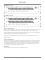
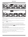
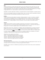
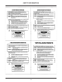
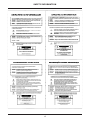
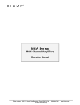
MCA Series
Multi-Channel
Amplifiers
Operation Manual
February 2012
Biamp Systems, 9300 SW Gemini Drive, Beaverton, Oregon 97008 U.S.A.
(503) 641-7287
www.biamp.com
IMPORTANT SAFETY INSTRUCTIONS
IMPORTANT SAFETY INSTRUCTIONS
1) Read these instructions.
2) Keep these instructions.
3) Heed all warnings.
4) Follow all instructions.
5) Do not use this product near water.
6) Clean only with dry cloth.
7) Do not block ventilation openings.
Install in accordance with the
manufacturer’s instructions.
8) Do not install near any heat
sources such as radiators, heat
registers, stoves, or other product
(including amplifiers) that produce
heat.
9) Do not defeat the safety purpose of
the grounding-type plug. A grounding
type plug has two blades and a third
grounding prong.
The third prong is provided for your
safety. If the provided plug does not
fit into your outlet, consult an
electrician for replacement of the
obsolete outlet.
10) Protect the power cord from being
walked on or pinched particularly at plugs,
convenience receptacles, and the point
where they exit from the product.
11) Only use attachments/accessories
specified by the manufacturer.
12) Use only with equipment rack, cart,
stand or table designed to provide adequate
mechanical strength, heat dissipation and
securement to the building structure.
When a cart is used, use
caution when moving the cart
and product combination to
avoid injury from tip-over.
13) Unplug this product during lightning
storms or when unused for long periods of
time.
14) Refer all servicing to qualified service
personnel. Servicing is required when the
product has been damaged in any way, such
as power-supply cord or plug is damaged,
liquid has been spilled or objects have fallen
into the product, the product has been
exposed to rain or moisture, does not
operate normally, or has been dropped.
WARNING - To reduce the risk of fire or electric shock, do not expose this product to rain or
moisture.
WARNING - This product employs Safety Grounding and must be connected to a MAINS
socket that is properly grounded to provide a protective eathing connection.
Disconnect Device - The MAINS plug is used to disconnect MAINS power and must be
installed near the equipment and remain readily accessible.
Explanation of safety related symbols - Product labeling and the operation manual may
use the internationally recognized symbols defined below to note safety messages.
Lightning Bolt: Hazardous Live voltages present when this unit is in operation. Do
not touch terminals marked with this symbol while the unit is connected to live power.
Exclamation Point: Replace components (i.e. fuses) only with the values specified by
the manufacturer. Failure to do so will compromise safe operation of this unit.
2
TABLE OF CONTENTS
MCA SERIES MULTI-CHANNEL AMPLIFIERS FEATURES. . . . . . . . . . . . . . . 4
FRONT PANEL . . . . . . . . . . . . . . . . . . . . . . . . . . . . . . . . . . . . . . . . . . . . . . . . . . . . . 5
REAR PANEL . . . . . . . . . . . . . . . . . . . . . . . . . . . . . . . . . . . . . . . . . . . . . . . . . . . . . . 6
BRIDGING . . . . . . . . . . . . . . . . . . . . . . . . . . . . . . . . . . . . . . . . . . . . . . . . . . . . . . . . 9
SPECIFICATIONS. . . . . . . . . . . . . . . . . . . . . . . . . . . . . . . . . . . . . . . . . . . . . . . . . 10
WARRANTY . . . . . . . . . . . . . . . . . . . . . . . . . . . . . . . . . . . . . . . . . . . . . . . . . . . . . . 11
EC DECLARATION. . . . . . . . . . . . . . . . . . . . . . . . . . . . . . . . . . . . . . . . . . . . . . . . . 12
SAFETY INFORMATION . . . . . . . . . . . . . . . . . . . . . . . . . . . . . . . . . . . . . . . . . . . 13
3
MCA MULTI-CHANNEL AMPLIFIERS
MCA Series Multi-Channel Amplifiers provide eight channels of power amplification. Model MCA
8050 delivers 50 watts/channel into 4 ohms. Model MCA 8150 delivers 150 watts/channel into 4
ohms. Channels may be bridged in pairs for higher combined wattage. MCA Series amplifiers are
covered by Biamp Systems’ five-year warranty.
FEATURES:
• 8 channels of 50W (MCA 8050) or 150W (MCA 8150)
• Channels may be bridged in pairs for combined power
• Balanced line-level inputs on plug-in barrier strips
• Rear panel level controls & high-pass filter switches
• Amplifier outputs on screw-terminal connectors
• Dual-color signal/peak indicators on front & rear panels
• Front panel indicators for amplifier temp/load faults
• Fan cooled with complete output/speaker protection
• Optional transformers for 25/70/100 Volt systems
• Incorporates AES recommended grounding practices
• CE marked and UL / C-UL listed
• CCC Certified
• Covered by Biamp Systems’ five-year warranty
4
FRONT PANEL
MCA 8050 Front Panel
MCA 8050
signal
peak
temp
fault
Channel 1
signal
peak
temp
fault
Channel 2
signal
peak
temp
fault
Channel 3
signal
peak
temp
fault
Channel 4
signal
peak
temp
fault
Channel 5
signal
peak
temp
fault
Channel 6
signal
peak
temp
fault
Channel 7
signal
peak
temp
fault
on
Channel 8
MCA 8150 Front Panel
MCA 8150
signal
peak
temp
fault
Channel 1
signal
peak
temp
fault
Channel 2
signal
peak
temp
fault
Channel 3
signal
peak
temp
fault
Channel 4
signal
peak
temp
fault
Channel 5
signal
peak
temp
fault
Channel 6
signal
peak
temp
fault
Channel 7
signal
peak
temp
fault
on
Channel 8
Signal / Peak Indicators
These 2-color LEDs indicate the signal level for each channel. When an LED is green, that channel
has signal (above -30dB). When an LED is red, that channel signal is clipping (max. power).
CAUTION: Signal levels should be adjusted to avoid clipping. Clipping can cause severe distortion,
over-temperature conditions, and even loudspeaker damage.
NOTE: Signal / Peak indicators will turn off during Temp / Fault conditions (see Temp / Fault
Indicators below).
Temp / Fault Indicators
These red LEDs indicate over-temperature and output fault conditions for each channel. When an
LED remains lit, that channel has an over-temperature condition. When an LED is flashing, that
channel has an output fault condition. Either condition will temporarily de-activate the channel,
causing the Signal / Peak LED to turn off as well. The channel will attempt to self-reset once the
over-temperature or output fault condition is resolved.
On Indicator
This green LED remains lit when AC power is applied to the unit.
5
REAR PANEL
input
2
outputs
1
level
level
2
outputs
input
3
level
signal / peak
outputs
level
OFF
OFF
OFF
4
input
1
2
HPF
BRIDGE
HPF
input
5
signal / peak
outputs
level
signal / peak
6
input
3
level
OFF
OFF
OFF
input
7
level
Designed in Oregon, U.S.A.
Assembled in India
4
OFF
OFF
OFF
outputs
level
BIAMP SYSTEMS
HPF
BRIDGE
HPF
8
input
level
signal / peak
level
5
6
OFF
OFF
OFF
115
7
8
HPF
BRIDGE
HPF
52SJ
signal / peak
MCA 8050
CAUTION
RISK OF ELECTRICAL SHOCK.
DO NOT OPEN.
US
signal / peak
R
signal / peak
UL
LISTED
OFF
OFF
OFF
O
C
HPF
BRIDGE
HPF
CAUTION:
Risk of fire replace fuse only
with same type
115V: F 10 A H 250 V
230V: T 4 A L 250 V
signal / peak
FUSE
FUSE
MCA 8050 Rear Panel
input
Class 2 Wiring
~115/230VAC 50-60Hz 900 Watts
MCA 8150 Rear Panel
MCA 8150
CAUTION
Designed in Oregon, U.S.A.
Assembled in India
outputs
input
3
1
2
input
signal / peak
4
input
5
level
HPF
BRIDGE
HPF
input
level
signal / peak
outputs
3
4
signal / peak
6
input
level
OFF
OFF
OFF
input
7
level
HPF
BRIDGE
HPF
outputs
5
6
signal / peak
8
input
level
signal / peak
level
OFF
OFF
OFF
7
8
HPF
BRIDGE
HPF
115
BIAMP SYSTEMS
US
signal / peak
R
52SJ
signal / peak
UL
LISTED
OFF
OFF
OFF
O
C
HPF
BRIDGE
HPF
CAUTION:
Risk of fire replace fuse only
with same type
115V: F 15 A H 250 V
230V: T 6.3 A L 250 V
signal / peak
FUSE
FUSE
RISK OF ELECTRICAL SHOCK.
DO NOT OPEN.
input
1
Class 2 Wiring
~115/230VAC 50-60Hz 1800 Watts
Input
These plug-in barrier strips provide the balanced line-level inputs to the channels. For balanced
connection, wire high (+), low (-), and ground ( ). For unbalanced connection, wire high (+) and
ground to both ( ) & (-).
NOTE: When using a pair of channels in ‘bridged’ mode (see Bridge below), input signal must be
connected to the odd numbered channel.
Level
These screw-driver adjustable controls determine the level of input signals allowed into the
channels. Level provides a gain range from ‘off’ (min.) to ‘unity’ (max.). The Level control is
factory set for -24dB of gain, which will produce maximum output power with input signal peaks of
+24dBu. For best performance, first adjust the source signals for optimum (maximum) levels, then
adjust the MCA Series Level controls for the desired volume.
Signal / Peak Indicators
These 2-color LEDs indicate the signal level for each channel. When an LED is green, that channel
has signal (above -30dB). When an LED is red, that channel signal is clipping (max. power).
CAUTION: Signal levels should be adjusted to avoid clipping. Clipping can cause severe distortion,
over-temperature conditions, and even loudspeaker damage.
NOTE: Signal / Peak indicators will turn off during Temp / Fault condition (see Temp / Fault
Indicators on pg. 5).
6
REAR PANEL
HPF
These DIP switches provide High-Pass Filters for the input channels. High-Pass Filters are used
to eliminate unnecessary lower frequencies (12dB/octave @ 125Hz) for speech and distributed
speaker applications. From the factory, the High-Pass Filters are bypassed (switches up). To assign
a High-Pass Filter on an input channel, move the switch to the down position.
CAUTION: To avoid output fault conditions, High-Pass Filters must be assigned on channels driving
25/70/100 Volt speaker systems (see Output below). Also, any other system equalization affecting
frequencies below 125 Hz should remain flat or be used as cut-only.
Bridge
These DIP switches allow adjacent channels to Bridge together in pairs, for a higher, combined
output power (see Bridging on pg. 9). Bridge disables the even numbered input, and applies
the odd numbered input signal to both amplifier channels. From the factory, Bridge is bypassed
(switches up). To assign Bridge to a pair of channels, move the switch to the down position.
Output
These screw terminals provide the speaker outputs from the channels. Connect the positive
speaker line to the (+) terminal and the negative speaker line to the (-) terminal of the channel
being used. The minimum speaker load on an individual channel is 4 ohms.
NOTE: When using a pair of channels in ‘bridged’ mode (see Bridge above), connect the positive
speaker line to the (+) terminal of the odd numbered channel and the negative speaker line to
the (+) terminal of the even numbered channel. The minimum speaker load for a bridged output
is 8 ohms. Output transformers for 25/70/100 Volt speaker systems are available as an option
(installation instructions are included with the output transformers).
Transformers (by model) are as follows:
TDT50 = MCA 8050 individual channels (50 Watts)
TDT100 = MCA 8050 bridged channels (100 Watts)
TDT150 = MCA 8150 individual channels (150 Watts)
TDT300 = MCA 8150 bridged channels (300 Watts)
AC Power Entrance
The switch applies AC power to the unit. The receptacle accepts the detachable AC Power Cord. The
AC Power Cord is for connection to three-prong grounded AC outlets.
CAUTION: Do not remove or defeat the ground prong on the AC Power Cord, as this constitutes a
shock hazard.
7
REAR PANEL
Line Voltage Selector Switch
Set this switch to “115” for nominal line voltages of 110-120 VAC. Set this switch to “230” for
nominal line voltages of 220-240 VAC. Make sure that the appropriate fuse is installed when
changing voltage selections.
Fuse
Replace Fuse with same type
MCA 8050 @ 115VAC Fuse =
MCA 8050 @ 230VAC Fuse =
MCA 8150 @ 115VAC Fuse =
MCA 8150 @ 230VAC Fuse =
and value only.
F 10 A H 250 V
T 4 A L 250 V
F 15 A H 250 V
T 6.3 A L 250 V
NOTE: If the Fuse continues to blow (even after checking for proper output connections and speaker
loads) the amplifier may require service.
8
BRIDGING
Bridge DIP switches allow the adjacent odd/even numbered channels to be bridged together in
pairs, for a higher, combined output power (see Bridge on pg. 7). When a pair of channels are
bridged, their wattage is combined, but the minimum load increases to 8 ohms (MCA 8050 = 100
watts @ 8 ohms; MCA 8150 = 300 watts @ 8 ohms). Bridge disables the even numbered input,
and applies the odd numbered input signal to both amplifier channels. From the factory, Bridge
is bypassed (switches up). To assign Bridge to a pair of channels, move the related switch to the
down position. Connect the source signal to the odd numbered input channel, connect the positive
speaker line to the (+) output terminal of the odd numbered channel, and connect the negative
speaker line to the (+) output terminal of the even numbered channel (see diagram on right).
NOTE: Only adjacent odd/even numbered channels, which share a common Bridge switch, can be
bridged. When channels are bridged, the minimum load is increased to 8 ohms. The negative (-)
output terminals on bridged channels are not used (no connection).
input
2
OFF
OFF
OFF
level
outputs
speaker
negative
level
input
1
speaker
positive
9
signal / peak
1
2
HPF
BRIDGE
HPF
signal / peak
source
signal
SPECIFICATIONS
MCA 8050 SPECIFICATIONS
Maximum Power Output (@ 2kHz):
Individual channel into 4 ohm load
Individual channel into 8 ohm load
Bridged channels into 8 ohm load
MCA 8150 SPECIFICATIONS
50 watts/channel
30 watts/channel
100 watts
Maximum Power Output (@ 2kHz):
Individual channel into 4 ohm load
Individual channel into 8 ohm load
Bridged channels into 8 ohm load
150 watts/channel
90 watts/channel
300 watts
Signal-to-Noise Ratio
(20Hz~20kHz @ rated power):
> 85dB
Signal-to-Noise Ratio
(20Hz~20kHz @ rated power):
> 85dB
THD + Noise
(20Hz~20kHz @ rated power):
< 0.2%
THD + Noise
(20Hz~20kHz @ rated power):
< 0.2%
Intermodulation Distortion (SMPTE):
< 0.35%
Frequency Response (20Hz~20kHz):
+0/-1dB
Input Impedance:
Balanced
Unbalanced
20k ohms
10k ohms
Input Sensitivity:
0.775 Vrms (0dBu)
Intermodulation Distortion (SMPTE):
< 0.35%
Frequency Response (20Hz~20kHz):
+0/-1dB
Input Impedance:
Balanced
Unbalanced
20k ohms
10k ohms
Input Sensitivity:
0.775 Vrms (0dBu)
Channel High-Pass Filters:
12dB/octave @ 120Hz
Channel High-Pass Filters:
12dB/octave @ 120Hz
Power Requirements:
115/230VAC 50/60Hz
Power Requirements:
115/230VAC 50/60Hz
900 watts max.
Power Consumption:
1800 watts max..
Power Consumption:
Dimensions:
Height (2 rack spaces)
Width
Depth
Weight:
Compliance:
3.5 inches (89mm)
19 inches (483mm)
15.5 inches (394mm)
30 lbs. (13.6kg)
AES48-2005 Grounding
& EMC practices
EU Directive 2002/95/EC, RoHS directive
CE marked
UL / C-UL listed
CCC Certified
Dimensions:
Height (3 rack spaces)
Width
Depth
5.25 inches (133mm)
19 inches (483mm)
15.5 inches (394mm)
Weight:
Compliance:
35 lbs. (15.9kg)
AES48-2005 Grounding
& EMC practices
EU Directive 2002/95/EC, RoHS directive
CE marked
UL / C-UL listed
CCC Certified
Biamp Systems reserves the right to make changes to performance specifications without prior notice.
10
WARRANTY
BIAMP SYSTEMS IS PLEASED TO EXTEND THE FOLLOWING 5-YEAR LIMITED WARRANTY TO THE
ORIGINAL PURCHASER OF THE PROFESSIONAL SOUND EQUIPMENT DESCRIBED IN THIS MANUAL
1. B
iamp Systems warrants to the original purchaser of new products that the product
will be free from defects in material and workmanship for a period of 5 YEARS from
the date of purchase from an authorized Biamp Systems dealer, subject to the
terms and conditions set forth below.
2. I f you notify Biamp during the warranty period that a Biamp Systems product fails to
comply with the warranty, Biamp Systems will repair or replace, at Biamp Systems’ option,
the nonconforming product. As a condition to receiving the benefits of this warranty, you
must provide Biamp Systems with documentation that establishes that you were the original
purchaser of the products. Such evidence may consist of your sales receipt from an authorized
Biamp Systems dealer. Transportation and insurance charges to and from the Biamp Systems
factory for warranty service shall be your responsibility.
3. T
his warranty will be VOID if the serial number has been removed or defaced; or if the
product has been altered, subjected to damage, abuse or rental usage, repaired by any
person not authorized by Biamp Systems to make repairs; or installed in any manner that
does not comply with Biamp Systems’ recommendations.
4. E
lectro-mechanical fans, electrolytic capacitors, gooseneck microphones, cords connecting
handheld microphones, hard-drives, displays, and normal wear and tear of items such as
paint, knobs, handles, keypads and covers are not covered under this warranty. All serverbased devices are warranted for 3 years only.
5. T
his warranty is in lieu of all other warranties, expressed or implied. Biamp Systems disclaims
all other warranties, expressed or implied, including, but not limited to, implied warranties of
merchantability and fitness for a particular purpose.
6. T
he remedies set forth herein shall be the purchaser’s sole and exclusive remedies with
respect to any defective product.
7. N
o agent, employee, distributor or dealer of Biamp Systems is authorized to modify this
warranty or to make additional warranties on behalf of Biamp Systems. Statements,
representations or warranties made by any dealer do not constitute warranties by Biamp
Systems. Biamp Systems shall not be responsible or liable for any statement, representation
or warranty made by any dealer or other person.
8. N
o action for breach of this warranty may be commenced more than one year after the
expiration of this warranty.
9. B
iamp Systems shall not be liable for special, indirect, incidental, or consequential damages,
including lost profits or loss of use arising out of the purchase, sale, or use of the products,
even if Biamp Systems was advised of the possibility of such damages.
022012_585.0075.90B
11
COMPLIANCE
12
SAFETY INFORMATION
13
SAFETY INFORMATION
14
SAFETY INFORMATION
15