1
INSTALLATION AND
OPERATION MANUAL
RICi-622GE
Gigabit Ethernet over 2 x STM-4/OC-12
Network Termination Unit
Version 1.0
The Access Company
RICi-622GE
Gigabit Ethernet over 2 x STM-4/OC-12 Network
Termination Unit
Version 1.0
Installation and Operation Manual
Notice
This manual contains information that is proprietary to RAD Data Communications Ltd. ("RAD").
No part of this publication may be reproduced in any form whatsoever without prior written
approval by RAD Data Communications.
Right, title and interest, all information, copyrights, patents, know-how, trade secrets and other
intellectual property or other proprietary rights relating to this manual and to the RICi-622GE and
any software components contained therein are proprietary products of RAD protected under
international copyright law and shall be and remain solely with RAD.
The RICi-622GE product name is owned by RAD. No right, license, or interest to such trademark
is granted hereunder, and you agree that no such right, license, or interest shall be asserted by
you with respect to such trademark. The RAD name, logo, logotype, and the terms EtherAccess,
TDMoIP and TDMoIP Driven, and the product names Optimux and IPmux, are registered
trademarks of RAD Data Communications Ltd. All other trademarks are the property of their
respective holders.
You shall not copy, reverse compile or reverse assemble all or any portion of the Manual or the
RICi-622GE. You are prohibited from, and shall not, directly or indirectly, develop, market,
distribute, license, or sell any product that supports substantially similar functionality as the RICi622GE, based on or derived in any way from the RICi-622GE. Your undertaking in this paragraph
shall survive the termination of this Agreement.
This Agreement is effective upon your opening of the RICi-622GE package and shall continue
until terminated. RAD may terminate this Agreement upon the breach by you of any term hereof.
Upon such termination by RAD, you agree to return to RAD the RICi-622GE and all copies and
portions thereof.
For further information contact RAD at the address below or contact your local distributor.
International Headquarters
RAD Data Communications Ltd.
North America Headquarters
RAD Data Communications Inc.
24 Raoul Wallenberg Street
Tel Aviv 69719, Israel
Tel: 972-3-6458181
Fax: 972-3-6498250, 6474436
E-mail: [email protected]
900 Corporate Drive
Mahwah, NJ 07430, USA
Tel: (201) 5291100, Toll free: 1-800-4447234
Fax: (201) 5295777
E-mail: [email protected]
© 2008 RAD Data Communications Ltd.
Publication No. 523-200-10/08
Limited Warranty
RAD warrants to DISTRIBUTOR that the hardware in the RICi-622GE to be delivered hereunder
shall be free of defects in material and workmanship under normal use and service for a period
of twelve (12) months following the date of shipment to DISTRIBUTOR.
If, during the warranty period, any component part of the equipment becomes defective by
reason of material or workmanship, and DISTRIBUTOR immediately notifies RAD of such defect,
RAD shall have the option to choose the appropriate corrective action: a) supply a replacement
part, or b) request return of equipment to its plant for repair, or c) perform necessary repair at
the equipment's location. In the event that RAD requests the return of equipment, each party
shall pay one-way shipping costs.
RAD shall be released from all obligations under its warranty in the event that the equipment has
been subjected to misuse, neglect, accident or improper installation, or if repairs or
modifications were made by persons other than RAD's own authorized service personnel, unless
such repairs by others were made with the written consent of RAD.
The above warranty is in lieu of all other warranties, expressed or implied. There are no
warranties which extend beyond the face hereof, including, but not limited to, warranties of
merchantability and fitness for a particular purpose, and in no event shall RAD be liable for
consequential damages.
RAD shall not be liable to any person for any special or indirect damages, including, but not
limited to, lost profits from any cause whatsoever arising from or in any way connected with the
manufacture, sale, handling, repair, maintenance or use of the RICi-622GE, and in no event shall
RAD's liability exceed the purchase price of the RICi-622GE.
DISTRIBUTOR shall be responsible to its customers for any and all warranties which it makes
relating to RICi-622GE and for ensuring that replacements and other adjustments required in
connection with the said warranties are satisfactory.
Software components in the RICi-622GE are provided "as is" and without warranty of any kind.
RAD disclaims all warranties including the implied warranties of merchantability and fitness for a
particular purpose. RAD shall not be liable for any loss of use, interruption of business or
indirect, special, incidental or consequential damages of any kind. In spite of the above RAD
shall do its best to provide error-free software products and shall offer free Software updates
during the warranty period under this Agreement.
RAD's cumulative liability to you or any other party for any loss or damages resulting from any
claims, demands, or actions arising out of or relating to this Agreement and the RICi-622GE shall
not exceed the sum paid to RAD for the purchase of the RICi-622GE. In no event shall RAD be
liable for any indirect, incidental, consequential, special, or exemplary damages or lost profits,
even if RAD has been advised of the possibility of such damages.
This Agreement shall be construed and governed in accordance with the laws of the State of
Israel.
Product Disposal
To facilitate the reuse, recycling and other forms of recovery of waste
equipment in protecting the environment, the owner of this RAD product is
required to refrain from disposing of this product as unsorted municipal
waste at the end of its life cycle. Upon termination of the unit’s use,
customers should provide for its collection for reuse, recycling or other form
of environmentally conscientious disposal.
General Safety Instructions
The following instructions serve as a general guide for the safe installation and operation of
telecommunications products. Additional instructions, if applicable, are included inside the
manual.
Safety Symbols
This symbol may appear on the equipment or in the text. It indicates potential
safety hazards regarding product operation or maintenance to operator or service
personnel.
Warning
Danger of electric shock! Avoid any contact with the marked surface while the
product is energized or connected to outdoor telecommunication lines.
Protective ground: the marked lug or terminal should be connected to the building
protective ground bus.
Warning
Some products may be equipped with a laser diode. In such cases, a label with the
laser class and other warnings as applicable will be attached near the optical
transmitter. The laser warning symbol may be also attached.
Please observe the following precautions:
•
Before turning on the equipment, make sure that the fiber optic cable is intact
and is connected to the transmitter.
•
Do not attempt to adjust the laser drive current.
•
Do not use broken or unterminated fiber-optic cables/connectors or look
straight at the laser beam.
•
The use of optical devices with the equipment will increase eye hazard.
•
Use of controls, adjustments or performing procedures other than those
specified herein, may result in hazardous radiation exposure.
ATTENTION: The laser beam may be invisible!
In some cases, the users may insert their own SFP laser transceivers into the product. Users are
alerted that RAD cannot be held responsible for any damage that may result if non-compliant
transceivers are used. In particular, users are warned to use only agency approved products that
comply with the local laser safety regulations for Class 1 laser products.
Always observe standard safety precautions during installation, operation and maintenance of
this product. Only qualified and authorized service personnel should carry out adjustment,
maintenance or repairs to this product. No installation, adjustment, maintenance or repairs
should be performed by either the operator or the user.
Handling Energized Products
General Safety Practices
Do not touch or tamper with the power supply when the power cord is connected. Line voltages
may be present inside certain products even when the power switch (if installed) is in the OFF
position or a fuse is blown. For DC-powered products, although the voltages levels are usually
not hazardous, energy hazards may still exist.
Before working on equipment connected to power lines or telecommunication lines, remove
jewelry or any other metallic object that may come into contact with energized parts.
Unless otherwise specified, all products are intended to be grounded during normal use.
Grounding is provided by connecting the mains plug to a wall socket with a protective ground
terminal. If a ground lug is provided on the product, it should be connected to the protective
ground at all times, by a wire with a diameter of 18 AWG or wider. Rack-mounted equipment
should be mounted only in grounded racks and cabinets.
Always make the ground connection first and disconnect it last. Do not connect
telecommunication cables to ungrounded equipment. Make sure that all other cables are
disconnected before disconnecting the ground.
Some products may have panels secured by thumbscrews with a slotted head. These panels may
cover hazardous circuits or parts, such as power supplies. These thumbscrews should therefore
always be tightened securely with a screwdriver after both initial installation and subsequent
access to the panels.
Connecting AC Mains
Make sure that the electrical installation complies with local codes.
Always connect the AC plug to a wall socket with a protective ground.
The maximum permissible current capability of the branch distribution circuit that supplies power
to the product is 16A. The circuit breaker in the building installation should have high breaking
capacity and must operate at short-circuit current exceeding 35A.
Always connect the power cord first to the equipment and then to the wall socket. If a power
switch is provided in the equipment, set it to the OFF position. If the power cord cannot be
readily disconnected in case of emergency, make sure that a readily accessible circuit breaker or
emergency switch is installed in the building installation.
In cases when the power distribution system is IT type, the switch must disconnect both poles
simultaneously.
Connecting DC Power
Unless otherwise specified in the manual, the DC input to the equipment is floating in reference
to the ground. Any single pole can be externally grounded.
Due to the high current capability of DC power systems, care should be taken when connecting
the DC supply to avoid short-circuits and fire hazards.
DC units should be installed in a restricted access area, i.e. an area where access is authorized
only to qualified service and maintenance personnel.
Make sure that the DC power supply is electrically isolated from any AC source and that the
installation complies with the local codes.
The maximum permissible current capability of the branch distribution circuit that supplies power
to the product is 16A. The circuit breaker in the building installation should have high breaking
capacity and must operate at short-circuit current exceeding 35A.
Before connecting the DC supply wires, ensure that power is removed from the DC circuit. Locate
the circuit breaker of the panel board that services the equipment and switch it to the OFF
position. When connecting the DC supply wires, first connect the ground wire to the
corresponding terminal, then the positive pole and last the negative pole. Switch the circuit
breaker back to the ON position.
A readily accessible disconnect device that is suitably rated and approved should be incorporated
in the building installation.
If the DC power supply is floating, the switch must disconnect both poles simultaneously.
Connecting Data and Telecommunications Cables
Data and telecommunication interfaces are classified according to their safety status.
The following table lists the status of several standard interfaces. If the status of a given port
differs from the standard one, a notice will be given in the manual.
Ports
Safety Status
V.11, V.28, V.35, V.36, RS-530, X.21,
10 BaseT, 100 BaseT, Unbalanced E1,
E2, E3, STM, DS-2, DS-3, S-Interface
ISDN, Analog voice E&M
SELV
xDSL (without feeding voltage),
Balanced E1, T1, Sub E1/T1
TNV-1 Telecommunication Network Voltage-1:
FXS (Foreign Exchange Subscriber)
TNV-2 Telecommunication Network Voltage-2:
Ports whose normal operating voltage exceeds the
limits of SELV (usually up to 120 VDC or telephone
ringing voltages), on which overvoltages from
telecommunication networks are not possible. These
ports are not permitted to be directly connected to
external telephone and data lines.
FXO (Foreign Exchange Office), xDSL
(with feeding voltage), U-Interface
ISDN
TNV-3 Telecommunication Network Voltage-3:
Ports whose normal operating voltage exceeds the
limits of SELV (usually up to 120 VDC or telephone
ringing voltages), on which overvoltages from
telecommunication networks are possible.
Safety Extra Low Voltage:
Ports which do not present a safety hazard. Usually
up to 30 VAC or 60 VDC.
Ports whose normal operating voltage is within the
limits of SELV, on which overvoltages from
telecommunications networks are possible.
Always connect a given port to a port of the same safety status. If in doubt, seek the assistance
of a qualified safety engineer.
Always make sure that the equipment is grounded before connecting telecommunication cables.
Do not disconnect the ground connection before disconnecting all telecommunications cables.
Some SELV and non-SELV circuits use the same connectors. Use caution when connecting cables.
Extra caution should be exercised during thunderstorms.
When using shielded or coaxial cables, verify that there is a good ground connection at both
ends. The grounding and bonding of the ground connections should comply with the local codes.
The telecommunication wiring in the building may be damaged or present a fire hazard in case of
contact between exposed external wires and the AC power lines. In order to reduce the risk,
there are restrictions on the diameter of wires in the telecom cables, between the equipment
and the mating connectors.
Caution
To reduce the risk of fire, use only No. 26 AWG or larger telecommunication line
cords.
Attention
Pour réduire les risques s’incendie, utiliser seulement des conducteurs de
télécommunications 26 AWG ou de section supérieure.
Some ports are suitable for connection to intra-building or non-exposed wiring or cabling only. In
such cases, a notice will be given in the installation instructions.
Do not attempt to tamper with any carrier-provided equipment or connection hardware.
Electromagnetic Compatibility (EMC)
The equipment is designed and approved to comply with the electromagnetic regulations of
major regulatory bodies. The following instructions may enhance the performance of the
equipment and will provide better protection against excessive emission and better immunity
against disturbances.
A good ground connection is essential. When installing the equipment in a rack, make sure to
remove all traces of paint from the mounting points. Use suitable lock-washers and torque. If an
external grounding lug is provided, connect it to the ground bus using braided wire as short as
possible.
The equipment is designed to comply with EMC requirements when connecting it with unshielded
twisted pair (UTP) cables. However, the use of shielded wires is always recommended, especially
for high-rate data. In some cases, when unshielded wires are used, ferrite cores should be
installed on certain cables. In such cases, special instructions are provided in the manual.
Disconnect all wires which are not in permanent use, such as cables used for one-time
configuration.
The compliance of the equipment with the regulations for conducted emission on the data lines
is dependent on the cable quality. The emission is tested for UTP with 80 dB longitudinal
conversion loss (LCL).
Unless otherwise specified or described in the manual, TNV-1 and TNV-3 ports provide secondary
protection against surges on the data lines. Primary protectors should be provided in the building
installation.
The equipment is designed to provide adequate protection against electro-static discharge (ESD).
However, it is good working practice to use caution when connecting cables terminated with
plastic connectors (without a grounded metal hood, such as flat cables) to sensitive data lines.
Before connecting such cables, discharge yourself by touching ground or wear an ESD preventive
wrist strap.
FCC-15 User Information
This equipment has been tested and found to comply with the limits of the Class A digital device,
pursuant to Part 15 of the FCC rules. These limits are designed to provide reasonable protection
against harmful interference when the equipment is operated in a commercial environment. This
equipment generates, uses and can radiate radio frequency energy and, if not installed and used
in accordance with the Installation and Operation manual, may cause harmful interference to the
radio communications. Operation of this equipment in a residential area is likely to cause harmful
interference in which case the user will be required to correct the interference at his own
expense.
Canadian Emission Requirements
This Class A digital apparatus meets all the requirements of the Canadian Interference-Causing
Equipment Regulation.
Cet appareil numérique de la classe A respecte toutes les exigences du Règlement sur le matériel
brouilleur du Canada.
Warning per EN 55022 (CISPR-22)
Warning
Avertissement
Achtung
This is a class A product. In a domestic environment, this product may cause radio
interference, in which case the user will be required to take adequate measures.
Cet appareil est un appareil de Classe A. Dans un environnement résidentiel, cet
appareil peut provoquer des brouillages radioélectriques. Dans ces cas, il peut être
demandé à l’utilisateur de prendre les mesures appropriées.
Das vorliegende Gerät fällt unter die Funkstörgrenzwertklasse A. In Wohngebieten
können beim Betrieb dieses Gerätes Rundfunkströrungen auftreten, für deren
Behebung der Benutzer verantwortlich ist.
Français
Mise au rebut du produit
Afin de faciliter la réutilisation, le recyclage ainsi que d'autres formes de
récupération d'équipement mis au rebut dans le cadre de la protection de
l'environnement, il est demandé au propriétaire de ce produit RAD de ne pas
mettre ce dernier au rebut en tant que déchet municipal non trié, une fois
que le produit est arrivé en fin de cycle de vie. Le client devrait proposer des
solutions de réutilisation, de recyclage ou toute autre forme de mise au rebut
de cette unité dans un esprit de protection de l'environnement, lorsqu'il aura
fini de l'utiliser.
Instructions générales de sécurité
Les instructions suivantes servent de guide général d'installation et d'opération sécurisées des
produits de télécommunications. Des instructions supplémentaires sont éventuellement
indiquées dans le manuel.
Symboles de sécurité
Ce symbole peut apparaitre sur l'équipement ou dans le texte. Il indique des risques
potentiels de sécurité pour l'opérateur ou le personnel de service, quant à
l'opération du produit ou à sa maintenance.
Avertissement
Danger de choc électrique ! Evitez tout contact avec la surface marquée tant que le
produit est sous tension ou connecté à des lignes externes de télécommunications.
Mise à la terre de protection : la cosse ou la borne marquée devrait être connectée
à la prise de terre de protection du bâtiment.
•
Avant la mise en marche de l'équipement, assurez-vous que le câble de fibre
optique est intact et qu'il est connecté au transmetteur.
•
Ne tentez pas d'ajuster le courant de la commande laser.
•
N'utilisez pas des câbles ou connecteurs de fibre optique cassés ou sans
terminaison et n'observez pas directement un rayon laser.
•
L'usage de périphériques optiques avec l'équipement augmentera le risque pour
les yeux.
•
L'usage de contrôles, ajustages ou procédures autres que celles spécifiées ici
pourrait résulter en une dangereuse exposition aux radiations.
ATTENTION : Le rayon laser peut être invisible !
Les utilisateurs pourront, dans certains cas, insérer leurs propres émetteurs-récepteurs Laser SFP
dans le produit. Les utilisateurs sont avertis que RAD ne pourra pas être tenue responsable de
tout dommage pouvant résulter de l'utilisation d'émetteurs-récepteurs non conformes. Plus
particulièrement, les utilisateurs sont avertis de n'utiliser que des produits approuvés par
l'agence et conformes à la réglementation locale de sécurité laser pour les produits laser de
classe 1.
Respectez toujours les précautions standards de sécurité durant l'installation, l'opération et la
maintenance de ce produit. Seul le personnel de service qualifié et autorisé devrait effectuer
l'ajustage, la maintenance ou les réparations de ce produit. Aucune opération d'installation,
d'ajustage, de maintenance ou de réparation ne devrait être effectuée par l'opérateur ou
l'utilisateur.
Manipuler des produits sous tension
Règles générales de sécurité
Ne pas toucher ou altérer l'alimentation en courant lorsque le câble d'alimentation est branché.
Des tensions de lignes peuvent être présentes dans certains produits, même lorsque le
commutateur (s'il est installé) est en position OFF ou si le fusible est rompu. Pour les produits
alimentés par CC, les niveaux de tension ne sont généralement pas dangereux mais des risques
de courant peuvent toujours exister.
Avant de travailler sur un équipement connecté aux lignes de tension ou de télécommunications,
retirez vos bijoux ou tout autre objet métallique pouvant venir en contact avec les pièces sous
tension.
Sauf s'il en est autrement indiqué, tous les produits sont destinés à être mis à la terre durant
l'usage normal. La mise à la terre est fournie par la connexion de la fiche principale à une prise
murale équipée d'une borne protectrice de mise à la terre. Si une cosse de mise à la terre est
fournie avec le produit, elle devrait être connectée à tout moment à une mise à la terre de
protection par un conducteur de diamètre 18 AWG ou plus. L'équipement monté en châssis ne
devrait être monté que sur des châssis et dans des armoires mises à la terre.
Branchez toujours la mise à la terre en premier et débranchez-la en dernier. Ne branchez pas des
câbles de télécommunications à un équipement qui n'est pas mis à la terre. Assurez-vous que
tous les autres câbles sont débranchés avant de déconnecter la mise à la terre.
Français
Certains produits peuvent être équipés d'une diode laser. Dans de tels cas, une
étiquette indiquant la classe laser ainsi que d'autres avertissements, le cas échéant,
sera jointe près du transmetteur optique. Le symbole d'avertissement laser peut
aussi être joint.
Avertissement
Veuillez observer les précautions suivantes :
Français
Connexion au courant du secteur
Assurez-vous que l'installation électrique est conforme à la réglementation locale.
Branchez toujours la fiche de secteur à une prise murale équipée d'une borne protectrice de mise
à la terre.
La capacité maximale permissible en courant du circuit de distribution de la connexion alimentant
le produit est de 16A. Le coupe-circuit dans l'installation du bâtiment devrait avoir une capacité
élevée de rupture et devrait fonctionner sur courant de court-circuit dépassant 35A.
Branchez toujours le câble d'alimentation en premier à l'équipement puis à la prise murale. Si un
commutateur est fourni avec l'équipement, fixez-le en position OFF. Si le câble d'alimentation ne
peut pas être facilement débranché en cas d'urgence, assurez-vous qu'un coupe-circuit ou un
disjoncteur d'urgence facilement accessible est installé dans l'installation du bâtiment.
Le disjoncteur devrait déconnecter simultanément les deux pôles si le système de distribution de
courant est de type IT.
Connexion d'alimentation CC
Sauf s'il en est autrement spécifié dans le manuel, l'entrée CC de l'équipement est flottante par
rapport à la mise à la terre. Tout pôle doit être mis à la terre en externe.
A cause de la capacité de courant des systèmes à alimentation CC, des précautions devraient
être prises lors de la connexion de l'alimentation CC pour éviter des courts-circuits et des risques
d'incendie.
Les unités CC devraient être installées dans une zone à accès restreint, une zone où l'accès n'est
autorisé qu'au personnel qualifié de service et de maintenance.
Assurez-vous que l'alimentation CC est isolée de toute source de courant CA (secteur) et que
l'installation est conforme à la réglementation locale.
La capacité maximale permissible en courant du circuit de distribution de la connexion alimentant
le produit est de 16A. Le coupe-circuit dans l'installation du bâtiment devrait avoir une capacité
élevée de rupture et devrait fonctionner sur courant de court-circuit dépassant 35A.
Avant la connexion des câbles d'alimentation en courant CC, assurez-vous que le circuit CC n'est
pas sous tension. Localisez le coupe-circuit dans le tableau desservant l'équipement et fixez-le
en position OFF. Lors de la connexion de câbles d'alimentation CC, connectez d'abord le
conducteur de mise à la terre à la borne correspondante, puis le pôle positif et en dernier, le
pôle négatif. Remettez le coupe-circuit en position ON.
Un disjoncteur facilement accessible, adapté et approuvé devrait être intégré à l'installation du
bâtiment.
Le disjoncteur devrait déconnecter simultanément les deux pôles si l'alimentation en courant CC
est flottante.
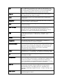
Glossary
Address
A coded representation of the origin or destination of data.
Agent
In SNMP, this refers to the managed system.
Analog
A continuous wave or signal (such as human voice).
ANSI
American National Standards Institute.
AWG
The American Wire Gauge System, which specifies wire width.
Balanced
A transmission line in which voltages on the two conductors are
equal in magnitude, but opposite in polarity, with respect to
ground.
Bandwidth
The range of frequencies passing through a given circuit. The
greater the bandwidth, the more information can be sent through
the circuit in a given amount of time.
Baud
Unit of signaling speed equivalent to the number of discrete
conditions or events per second. If each signal event represents
only one bit condition, baud rate equals bps (bits per second).
Bipolar
Signaling method in E1/T1 representing a binary “1” by alternating
positive and negative pulses, and a binary “0” by absence of
pulses.
Bit
The smallest unit of information in a binary system. Represents
either a one or zero (“1” or “0”).
bps (Bits Per Second)
A measure of data transmission rate in serial transmission.
Bridge
A device interconnecting local area networks at the OSI data link
layer, filtering and forwarding frames according to media access
control (MAC) addresses.
Buffer
A storage device. Commonly used to compensate for differences
in data rates or event timing when transmitting from one device to
another. Also used to remove jitter.
Bus
A transmission path or channel. A bus is typically an electrical
connection with one or more conductors, where all attached
devices receive all transmissions at the same time.
Byte
A group of bits (normally 8 bits in length).
Carrier
A continuous signal at a fixed frequency that is capable of being
modulated with a second (information carrying) signal.
Cell
The 53-byte basic information unit within an ATM network. The
user traffic is segmented into cells at the source and reassembled
at the destination. An ATM cell consists of a 5-byte ATM header
and a 48-byte ATM payload, which contains the user data.
Channel
A path for electrical transmission between two or more points.
Also called a link, line, circuit or facility.
Clock
A term for the source(s) of timing signals used in synchronous
transmission.
Congestion
A state in which the network is overloaded and starts to discard
user data (frames, cells or packets).
Data
Information represented in digital form, including voice, text,
facsimile and video.
Data Link Layer
Layer 2 of the OSI model. The entity, which establishes, maintains,
and releases data-link connections between elements in a
network. Layer 2 is concerned with the transmission of units of
information, or frames, and associated error checking.
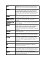
dBm
A measure of power in communications: the decibel in reference
to one milliwatt (0 dBm = 1 milliwatt and -30 dBm = .001
milliwatt).
Decibel
See dB.
Diagnostics
The detection and isolation of a malfunction or mistake in a
communications device, network or system.
Differential Delay
Differential delay is caused when traffic is split over different lines
that may traverse shorter and longer paths. Products like the RAD
IMX-2T1/E1 inverse multiplexer compensate for any differential
delay (up to 64 msec) between the T1 lines, to properly
reconstruct the original stream.
Digital
The binary (“1” or “0”) output of a computer or terminal. In data
communications, an alternating, non-continuous (pulsating) signal.
E3
The European standard for high speed digital transmission,
operating at 34 Mbps.
Encapsulation
Encapsulating data is a technique used by layered protocols in
which a low level protocol accepts a message from a higher level
protocol, then places it in the data portion of the lower-level
frame. The logistics of encapsulation require that packets traveling
over a physical network contain a sequence of headers.
Ethernet
A local area network (LAN) technology which has extended into
the wide area networks. Ethernet operates at many speeds,
including data rates of 10 Mbps (Ethernet), 100 Mbps (Fast
Ethernet), 1,000 Mbps (Gigabit Ethernet), 10 Gbps, 40 Gbps, and
100 Gbps.
Flow Control
A congestion control mechanism that results in an ATM system
implementing flow control.
Frame
A logical grouping of information sent as a link-layer unit over a
transmission medium. The terms packet, datagram, segment, and
message are also used to describe logical information groupings.
Framing
At the physical and data link layers of the OSI model, bits are fit
into units called frames. Frames contain source and destination
information, flags to designate the start and end of the frame,
plus information about the integrity of the frame. All other
information, such as network protocols and the actual payload of
data, is encapsulated in a packet, which is encapsulated in the
frame.
Full Duplex
A circuit or device permitting transmission in two directions
(sending and receiving) at the same time.
FXO (Foreign Exchange
Office)
A voice interface, emulating a PBX extension, as it appears to the
CO (Central Office) for connecting a PBX extension to a
multiplexer.
FXS (Foreign Exchange
Subscriber)
A voice interface, emulating the extension interface of a PBX (or
subscriber interface of a CO) for connecting a regular telephone
set to a multiplexer.
Gateway
Gateways are points of entrance and exit from a communications
network. Viewed as a physical entity, a gateway is that node that
translates between two otherwise incompatible networks or
network segments. Gateways perform code and protocol
conversion to facilitate traffic between data highways of differing
architecture.
Half Duplex
A circuit or device capable of transmitting in two directions, but
not at the same time.
Interface
A shared boundary, defined by common physical interconnection
characteristics, signal characteristics, and meanings of exchanged
signals.
IP Address
Also known as an Internet address. A unique string of numbers
that identifies a computer or device on a TCP/IP network. The
format of an IP address is a 32-bit numeric address written as four
numbers from 0 to 255, separated by periods (for example,
1.0.255.123).
J1
Digital interconnection protocol similar to T1 and E1 used in Japan.
Jitter
The deviation of a transmission signal in time or phase. It can
introduce errors and loss of synchronization in high speed
synchronous communications.
Laser
A device that transmits an extremely narrow and coherent beam
of electromagnetic energy in the visible light spectrum. Used as a
light source for fiber optic transmission (generally more expensive,
shorter lived, single mode only, for greater distances than LED).
Loopback
A type of diagnostic test in which the transmitted signal is
returned to the sending device after passing through all or part of
a communications link or network.
Manager
An application that receives Simple Network Management Protocol
(SNMP) information from an agent. An agent and manager share a
database of information, called the Management Information Base
(MIB). An agent can use a message called a traps-PDU to send
unsolicited information to the manager. A manager that uses the
RADview MIB can query the RAD device, set parameters, sound
alarms when certain conditions appear, and perform other
administrative tasks.
Master Clock
The source of timing signals (or the signals themselves) that all
network stations use for synchronization.
Multiplexer
At one end of a communications link, a device that combines
several lower speed transmission channels into a single high speed
channel. A multiplexer at the other end reverses the process.
Sometimes called a mux. See Bit Interleaving/Multiplexing.
Network
(1) An interconnected group of nodes. (2) A series of points,
nodes, or stations connected by communications channels; the
collection of equipment through which connections are made
between data stations.
Node
A point of interconnection to a network.
Packet
An ordered group of data and control signals transmitted through
a network, as a subset of a larger message.
Payload
The 48-byte segment of the ATM cell containing user data. Any
adaptation of user data via the AAL will take place within the
payload.
Physical Layer
Layer 1 of the OSI model. The layer concerned with electrical,
mechanical, and handshaking procedures over the interface
connecting a device to the transmission medium.
Policing
A method for verifying that the incoming VC complies with the
user’s service contract.
Port
The physical interface to a computer or multiplexer, for connection
of terminals and modems.
Prioritization
Also called CoS (class of service), classifies traffic into categories
such as high, medium, and low. The lower the priority, the more
“drop eligible” is a packet. When the network gets busy,
prioritization ensures critical or high-rated traffic is passed first,
and packets from the lowest categories may be dropped.
Protocol
A formal set of conventions governing the formatting and relative
timing of message exchange between two communicating
systems.
RADIUS (Remote
Authentication Dial-In
User Service)
An authentication, authorization and accounting protocol for
applications such as network access or IP mobility. Many network
services require the presentation of security credentials (such as a
username and password or security certificate) in order to connect
to the network. Before access to the network is granted, this
information is passed to a network access server (NAS) device
over the link-layer protocol, then to a RADIUS server over the
RADIUS protocol. The RADIUS server checks that the information is
correct using authentication schemes like PAP, CHAP or EAP.
Routing
The process of selecting the most efficient circuit path for a
message.
Serial Transmission
A common mode of transmission, where the character bits are
sent sequentially one at a time instead of in parallel.
Single Mode
Describing an optical wave-guide or fiber that is designed to
propagate light of only a single wavelength (typically 5-10 microns
in diameter).
Space
In telecommunications, the absence of a signal. Equivalent to a
binary 0.
Sync
See Synchronous Transmission.
Synchronous
Transmission
Transmission in which data bits are sent at a fixed rate, with the
transmitter and receiver synchronized.
T1
A digital transmission link with a capacity of 1.544 Mbps used in
North America. Typically channelized into 24 DS0s, each capable of
carrying a single voice conversation or data stream. Uses two pairs
of twisted pair wires.
Telnet
The virtual terminal protocol in the Internet suite of protocols. It
lets users on one host access another host and work as terminal
users of that remote host. Instead of dialing into the computer,
the user connects to it over the Internet using Telnet. When
issuing a Telnet session, it connects to the Telnet host and logs in.
The connection enables the user to work with the remote machine
as though a terminal was connected to it.
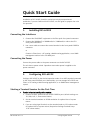
Quick Start Guide
Installation of RICi-622GE should be carried out only by an experienced
technician. If you are familiar with RICi-622GE, use this guide to prepare the units
for operation.
1.
Installing RICi-622GE
Connecting the Interfaces
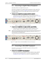
1. Connect the SDH/SONET equipment to the fiber optic front panel connectors.
2. Connect the 1000BaseT or 1000BaseSx/Lx / 100BaseSx/Lx LAN to the ETH
front panel connectors.
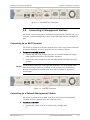
3. Use a cross cable to connect the control terminal to the front panel CONTROL
connector.
or
Connect a Telnet host, a PC running a Web browsing application, or an SNMP
management station to the ETH MNG port.
Connecting the Power
Connect the power cable to the power connector on the RICi-622GE.
The unit has no power switch. Operation starts when power is applied to the
power connector.
2.
Configuring RICi-622GE
Configure RICi-622GE to the desired operation mode via an ASCII terminal connected
to the front panel CONTROL port. Alternatively, you can manage RICi-622GE over
Telnet, a PC running a Web browsing application, or an SNMP-based management
system.
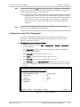
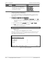
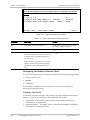
Starting a Terminal Session for the First Time
³
To start a terminal configuration session:
1. Connect an ASCII terminal to RICi-622GE CONTROL port (default settings are:
115,200; N; 8; 1; Flow control: None).
2. Set the terminal emulator to VT100 emulation for optimal view of system
menus.
3. If you are using HyperTerminal, set the terminal mode to 132-column mode
for optimal view of system menus (Properties>Settings>Terminal Setup
>132 column mode).
RICi-622GE Ver. 1.0
Configuring RICi-622GE
1
Quick Start Guide
Installation and Operation Manual
4. Power up RICi-622GE. Verify that the POWER LED in back panel is On.
5. Wait until the RDY indicator is ON, and then press <Enter> once to obtain the
login screen.
6. Enter your user name and password and proceed with the management
session.
Note
The RICi-622GE default user name is su, default password is 1234.
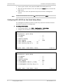
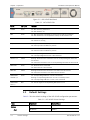
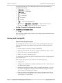
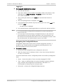
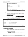
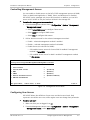
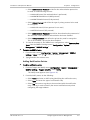
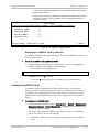
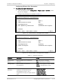
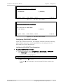
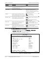
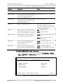
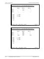
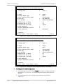
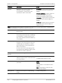
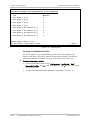
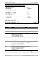
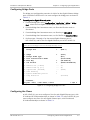
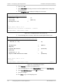
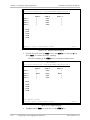
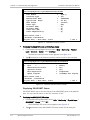
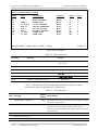
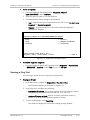
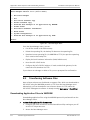
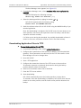
Configuring RICi-622GE via the Quick Setup Menu
The management software provides a Quick Setup menu that includes the basic
parameters necessary for configuration.
³
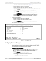
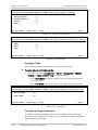
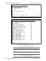
To configure RICi-622GE:
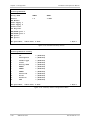
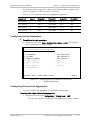
1. From the Main Menu, select Main > Configuration > Quick Setup.
2. Configure the parameters according to the table below.
RICi-622GE
Configuration > Quick Setup
1.
2.
3.
4.
5.
6.
>
IP address
IP mask
Default Gateway
Host Tagging
Host VLAN ID [1-4094]
Host Priority Tag [0-7]
...
...
...
>
(-)
(-)
(-)
(Yes)
... (1)
... (0)
ESC-prev. menu; !-main menu; &-exit;
1 M/ 2 C
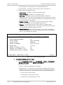
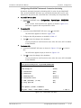
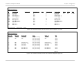
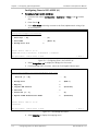
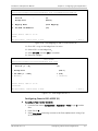
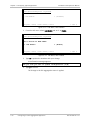
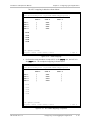
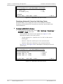
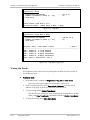
RICi-622GE
Configuration > Quick Setup
1.
2.
3.
4.
5.
6.
>
IP address
...
IP mask
...
Default Gateway
...
Host Tagging
>
SP Management VLAN ID [1-4094]
...
SP Management Priority Tag [0-7] ...
ESC-prev. menu; !-main menu; &-exit;
2
Configuring RICi-622GE
(-)
(-)
(-)
(No)
(1)
(0)
1 M/ 2 C
RICi-622GE Ver. 1.0
Installation and Operation Manual
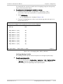
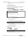
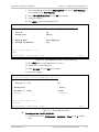
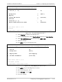
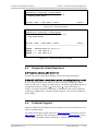
Quick Start Guide
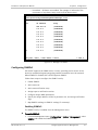
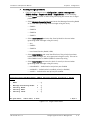
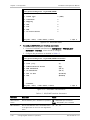
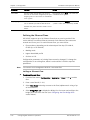
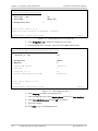
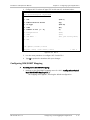
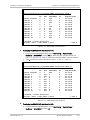
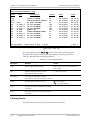
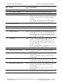
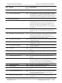
Parameter
Description
Possible Values
IP Address
Host IP address
0.0.0.0 to
255.255.255.255
IP Mask
Host IP mask
0.0.0.0 to
255.255.255.255
Default Gateway
Default gateway IP address
0.0.0.0 to
255.255.255.255
Host Tagging
Specifies if the Management station is using tagged or
untagged frames.
Yes
No
Host VLAN ID
Set the VID of the packets sent by host, if host tagging is
Yes
1-4094
Host Priority Tag
Set VLAN priority for packets sent by host, if host tagging
is Yes
0-7
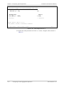
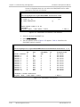
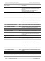
SP Management
VLAN ID
Set the VID for management traffic towards the
SP network, if host tagging is No
1-4094
SP Management
Priority Tag
Set VLAN priority for management traffic towards the SP
network, if host tagging is No
0-7
RICi-622GE Ver. 1.0
Configuring RICi-622GE
3
Quick Start Guide
4
Configuring RICi-622GE
Installation and Operation Manual
RICi-622GE Ver. 1.0
Contents
Chapter 1. Introduction 1.1 Overview.................................................................................................................... 1-1 Product Options...................................................................................................... 1-1 Gigabit Ethernet Ports ........................................................................................ 1-1 STM-4/OC-12 Ports ............................................................................................ 1-1 Applications ............................................................................................................ 1-2 Features ................................................................................................................. 1-2 Gigabit Ethernet Interface .................................................................................. 1-2 Ethernet Link Redundancy .................................................................................. 1-3 SDH/SONET Interface ......................................................................................... 1-3 SDH/SONET APS Support .................................................................................... 1-3 SDH/SONET Timing ............................................................................................. 1-3 EVC Mapping ...................................................................................................... 1-3 Encapsulation..................................................................................................... 1-4 Loop Detection .................................................................................................. 1-4 Fault Propagation ............................................................................................... 1-4 Management ...................................................................................................... 1-4 Diagnostics ........................................................................................................ 1-5 Statistics ............................................................................................................ 1-5 1.2 Physical Description ................................................................................................... 1-5 1.3 Functional Description................................................................................................ 1-6 Traffic Flow ............................................................................................................ 1-6 Encapsulation ......................................................................................................... 1-6 LAPS Encapsulation ............................................................................................ 1-6 GFP Encapsulation .............................................................................................. 1-7 Fault Propagation ................................................................................................... 1-8 1.4 Technical Specifications.............................................................................................. 1-8 Chapter 2. Installation and Setup 2.1 2.2 2.3 2.4 2.5 2.6 2.7 2.8 Site Requirements and Prerequisites .......................................................................... 2-1 Package Contents ...................................................................................................... 2-2 Required Equipment ................................................................................................... 2-2 Mounting the Unit ...................................................................................................... 2-2 Installing Fiber Optic SFP Modules .............................................................................. 2-3 Connecting to Gigabit Ethernet Equipment ................................................................. 2-4 Connecting to SDH/SONET Equipment ........................................................................ 2-4 Connecting to Management Stations .......................................................................... 2-5 Connecting to an ASCII Terminal .............................................................................. 2-5 Connecting to a Network Management Station........................................................ 2-5 2.9 Connecting to Power .................................................................................................. 2-6 Connecting to AC Power.......................................................................................... 2-6 Connecting to DC Power ......................................................................................... 2-7 Chapter 3. Operation 3.1 3.2 3.3 3.4 Turning On the Unit ................................................................................................... 3-1 Indicators .................................................................................................................. 3-1 Default Settings ......................................................................................................... 3-2 Configuration and Management Alternatives .............................................................. 3-6 RICi-622GE Ver. 1.0
i
Table of Contents
Installation and Operation Manual
Working with Terminal ............................................................................................ 3-7 Logging In .......................................................................................................... 3-8 Choosing Options ............................................................................................... 3-8 Terminal Hot Keys .............................................................................................. 3-9 Ending a Terminal Configuration Session........................................................... 3-11 Working with ConfiguRAD ..................................................................................... 3-11 Web Browser Requirements ............................................................................. 3-11 Logging In ........................................................................................................ 3-11 Navigating the ConfiguRAD Menus .................................................................... 3-12 Menu Maps ........................................................................................................... 3-12 3.5 Turning Off the Unit ................................................................................................. 3-15 Chapter 4. Configuration 4.1 Configuring RICi-622GE for Management .................................................................... 4-1 Defining Host IP Parameters ................................................................................... 4-1 Entering Device Information .................................................................................... 4-3 Configuring Host Encapsulation ............................................................................... 4-3 Controlling Management Access .............................................................................. 4-5 Configuring User Access .......................................................................................... 4-5 Configuring Network Managers ............................................................................... 4-6 Configuring SNMPv3 ................................................................................................ 4-7 Enabling SNMPv3 ................................................................................................ 4-7 Adding SNMPv3 Users ........................................................................................ 4-8 Adding Notification Entries ................................................................................. 4-9 Assigning Traps ................................................................................................ 4-10 Configuring Target Parameters ......................................................................... 4-10 Configuring Target Address .............................................................................. 4-12 Mapping SNMPv1 to SNMPv3 ............................................................................ 4-12 Returning to SNMPv3 Factory Defaults ............................................................. 4-13 Configuring RADIUS Client ..................................................................................... 4-13 Configuring Control Port Parameters ..................................................................... 4-15 4.2 Configuring RICi-622GE for Operation ....................................................................... 4-16 Setting Physical Layer Parameters ......................................................................... 4-16 Configuring Ethernet Interface.......................................................................... 4-16 Configuring SDH/SONET Interface ..................................................................... 4-19 Configuring Fault Propagation ............................................................................... 4-28 Configuring the Logical Layer ................................................................................ 4-29 Configuring RICi-622GE at the Application Level..................................................... 4-33 Configuring the Bridge Ports ............................................................................. 4-33 Configuring the Quality of Service (QoS) ........................................................... 4-38 Defining the Ethernet Flows ............................................................................. 4-42 4.3 Additional Tasks ....................................................................................................... 4-48 Configuring Date and Time .................................................................................... 4-48 Viewing Inventory ................................................................................................. 4-49 Transferring Software and Configuration Files ....................................................... 4-52 Resetting RICi-622GE ............................................................................................ 4-52 Returning to Factory Defaults........................................................................... 4-53 Resetting the RICi-622GE Unit .......................................................................... 4-53 Chapter 5. Configuring Typical Applications 5.1 Configuring a Point-to-Point Application ..................................................................... 5-1 Configuring System Parameters............................................................................... 5-2 ii
RICi-622GE Ver. 1.0
Installation and Operation Manual
Table of Contents
Configuring Bridge Ports ......................................................................................... 5-3 Configuring the Flows ............................................................................................. 5-3 Configuring flows in RICi-622GE (A) .................................................................... 5-4 Configuring flows in RICi-622GE (B) .................................................................... 5-7 5.2 Configuring a Traffic Aggregation Application ........................................................... 5-12 Configuring System Parameters............................................................................. 5-13 Configuring Ethernet Link Aggregation .................................................................. 5-13 Configuring Logical Layer ...................................................................................... 5-15 Configuring SDH/SONET Mapping .......................................................................... 5-17 Configuring the Flows ........................................................................................... 5-20 Chapter 6. Troubleshooting and Diagnostics 6.1 Monitoring Performance ............................................................................................. 6-1 Viewing Physical Layer Status .................................................................................. 6-1 Displaying Ethernet Status ................................................................................. 6-1 Displaying SDH/SONET Status ............................................................................. 6-2 Displaying Automatic Protection Switching Status ............................................... 6-4 Displaying Timing Source .................................................................................... 6-5 Displaying Flow Status ............................................................................................ 6-6 Viewing Physical Layer Statistics .............................................................................. 6-6 Displaying Ethernet Statistics ............................................................................. 6-6 Displaying SDH/SONET Statistics ......................................................................... 6-8 Viewing Logical Layer Statistics ............................................................................. 6-11 6.2 Handling Alarms and Traps ....................................................................................... 6-13 Displaying Events .................................................................................................. 6-13 Clearing Events ..................................................................................................... 6-14 Displaying Alarms.................................................................................................. 6-15 6.3 Troubleshooting ....................................................................................................... 6-21 6.4 Testing RICi-622GE ................................................................................................... 6-22 Running Diagnostic Loopbacks .............................................................................. 6-22 Running a Ping Test .............................................................................................. 6-23 Tracing the Route ................................................................................................. 6-24 6.5 Frequently Asked Questions ..................................................................................... 6-25 6.6 Technical Support .................................................................................................... 6-25 Appendix A. Connector Wiring Appendix B. Boot Sequence and Downloading Software RICi-622GE Ver. 1.0
iii
Table of Contents
iv
Installation and Operation Manual
RICi-622GE Ver. 1.0
Chapter 1
Introduction
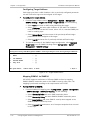
1.1
Overview
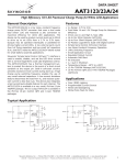
RICi-622GE is a network termination unit (NTU) that provides simple, efficient,
and cost effective Gigabit Ethernet connectivity over SDH/SONET networks. The
device can aggregate traffic from up to eight remote SDH/SONET sites. The unit
offers a migration path for connecting future-ready IP devices to the existing
SDH/SONET networks at up to 1.2 Gbps access rates. RICi-622GE enables
cost-effective deployment of the SDH/SONET infrastructure for Internet access
and LAN connectivity, while providing continued support for all legacy services.
The unit delivers carrier-grade Ethernet services as defined by the MEF:
•
EPL (Ethernet Private Line)
•
EVPL (Ethernet Virtual Private Line).
RICi-622GE has two Gigabit Ethernet ports and two STM-4/OC-12 ports that
support SFP-based fiber optic connectors. The Ethernet ports can also be ordered
with 10/100/1000BaseT interfaces. The STM-4/OC-12 ports offer either
622 Mbps with link bonding using VCAT (G.707/Y.1322) and LCAS (G.7042), or
1+1 link protection (unidirectional MSP/APS) to increase service uptime. The
Gigabit Ethernet ports offer redundancy based on link aggregation (802.3ad).
The unit supports powerful bandwidth profiles including CIR/CBS and EIR/EBS for
differentiated Ethernet services. RICi-622GE supports encapsulation using GFP per
ITU-T Rec. G.7041 or LAPS per ITU-T Rec. X.86, providing efficient bandwidth
utilization.
RICi-622GE can be managed via a local terminal port, via a dedicated out-of-band
Ethernet port, or inband through a user or network port. The device supports
Network Time Protocol and can obtain the time of day from a standard SNTP
server. RICi-622GE has two redundant power supplies, increasing its reliability.
Product Options
Gigabit Ethernet Ports
The two Gigabit Ethernet ports are available with the following interfaces:
•
1000BaseSx, LC connector (SFP)
•
1000BaseLx10, LC connector (SFP)
•
10/100/1000BaseT, RJ-45 connector.
The fiber optic interfaces support industry-standard Gigabit SFP hot-swappable
optical transceivers. The two ports must be either both fiber optic interface or
RICi-622GE Ver. 1.0
Overview
1-1
Chapter 1 Introduction
Installation and Operation Manual
both electrical interface. If they have fiber optic interface, the types can be
mixed.
STM-4/OC-12 Ports
The STM-4/OC-12 ports are available with the following SFP-based fiber optic
interfaces, in any combination:
•
1000BaseSx, LC connector (SFP)
•
1000BaseLx10, LC connector (SFP).
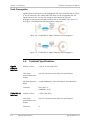
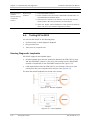
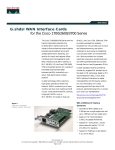
Applications
The application shown in Figure 1-1 illustrates point-to-point Ethernet private line
over SDH/SONET.
Figure 1-1. Point-to-Point Connection with Ethernet Flows over SDH/SONET
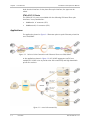
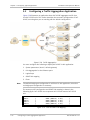
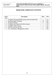
In the application shown in Figure 1-2, RICi-622GE aggregates traffic from
multiple RICi-155GE units to provide Inter-PoP connectivity and high-bandwidth
private line services.
Figure 1-2. Inter-PoP connectivity
1-2
Overview
RICi-622GE Ver. 1.0
Installation and Operation Manual
Chapter 1 Introduction
Features
Ethernet Link Redundancy
The Gigabit Ethernet ports can act as bridge ports or be aggregated to provide
Gigabit Ethernet link redundancy, to allow reliable and uninterrupted service. The
RICi-622GE unit supports Gigabit Ethernet link redundancy based on the link
aggregation protocol IEEE 802.3ad.
SDH/SONET APS Support
RICi-622GE supports 1+1 link protection (unidirectional MSP/APS) on the
SDH/SONET links, according to the ITU-T G.841 requirements. K1/K2 byte
functionality is provided according to Telecordia GR-253 and ITU-T G.783.
Additional protection is provided by the VCAT and LCAS protocols.
SDH/SONET Timing
You can define a master clock source, and a fallback source to be used if the
master clock source fails. The SDH/SONET clock source can be one of the
following:
•
Internal – Reference source generated by the RICi-622GE internal oscillator
•
Rx clock – Reference source locked to the receive clock recovered from the
line signal of the STM-1/OC-3c interface.
EVC Mapping
The ingress user traffic is mapped to the Ethernet flows (EVCs) using the
following per-port criteria:
•
Port-based (All-to-one bundling)
•
User port + CE-VID
•
User port + CE-VLAN priority.
RICi-622GE supports up to 16 Ethernet flows.
Policing and Bandwidth Profiles
RICi-622GE provides per-flow dual token bucket policing that enables CIR/CBS and
EIR/EBS.
Traffic Prioritization and Quality of Service
Once traffic is classified to EVC or EVC.CoS, it is mapped to one four priority
queues. The unit uses WRED (tail-drop) policy to ensure that queues are not
congested and high-priority traffic is not dropped.
RICi-622GE Ver. 1.0
Overview
1-3
Chapter 1 Introduction
Installation and Operation Manual
Encapsulation
The Ethernet traffic is encapsulated for transmission over SDH/SONET network
using one of the following link layer protocols:
•
Link Access Procedure for SDH/SONET (LAPS) protocols in accordance with
ITU-T Rec. X.86 draft recommendations
•
Generic Framing Procedure (GFP) in accordance with ITU-T Rec. G.7041,
ANSI T1-105.02, framed mode.
The traffic encapsulation type is user-configurable.
Loop Detection
RICi-622GE features a mechanism to detect Ethernet loops in the Ethernet
interface and SDH network, and avoid them by disabling the bridge port.
The loop detection mechanism is based on periodic transmission of Ethernet
loop detection frames with source and destination address equal to the MAC
address of the originating RICi-622GE device, so they do not propagate in the
network beyond the opposite Ethernet bridge port.
When the loop detection mechanism is active, loop detection frames are sent
once every five seconds. If a loop detection frame is received back at the sending
port three times within 20 seconds, a loop is declared, the LOOP DETECTED trap
is sent, and the bridge port is disabled for four minutes. At the end of the four
minutes, the bridge port is restored to service and loop detection frames are
again transmitted.
Fault Propagation
The unit provides user-configurable bidirectional fault propagation. SDH/SONET
alarms can optionally propagate and cause the Gigabit Ethernet link to shut
down. Gigabit Ethernet alarms can also be propagated over the SDH/SONET link
Management
Setup, monitoring, and diagnostics can be performed using one of the following
methods:
•
•
Out-of-band via ASCII terminal connected to the V.24/RS-232 DCE control port
Network management using Telnet, terminal Web-based application, or an
SNMP-based management system:
Inband management via user or network port
Out-of-band management via the dedicated 10/100BaseT management
port.
ConfiguRAD
ConfiguRAD is a user-friendly Web-based terminal management system that
provides remote device configuration and maintenance. It is embedded into
RICi-622GE and provided at no extra cost. ConfiguRAD can be run from any
standard Web browser.
1-4
Overview
RICi-622GE Ver. 1.0
Installation and Operation Manual
Chapter 1 Introduction
Inband Management
For inband management, you can configure the RICi-622GE host for tagged or
untagged operation:
•
When host tagging is enabled, the host packets receive a VLAN tag, creating a
dedicated management VLAN.
•
When tagging is disabled, no traffic separation is performed, and
management packets can be forwarded to the user port.
Security
The following security protocols are provided by RICi-622GE to ensure clientserver communication privacy and correct user authentication:
•
RADIUS (client authentication only)
•
SSLv3 for Web-based management application
•
SSHv2 for Secure Shell communication session
•
SNMPv3 (SNMPv1 is used if SNMPv3 is not enabled).
Diagnostics
Loopbacks can be closed on any of the SDH/SONET ports. Only one loopback can
be active at a time. When the loopback is active, data coming from the
SDH/SONET network is looped back to the SDH/SONET network, disrupting the
traffic.
Statistics
RICi-622GE collects performance statistics for the physical layers of the Gigabit
Ethernet ports and SDH/SONET ports, as well as for Ethernet flows and VCGs.
1.2
Physical Description
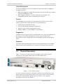
Figure 1-3 shows a 3D view of the front and back of RICi-622GE, with SFP
interfaces for the Gigabit Ethernet ports and SDH/SONET ports.
Figure 1-3. RICi-622GE, 3D View
The LEDs, interface connectors, and power connectors are located on the rear
panel. Some LEDs are also located on the front panel. The RICi-622GE interface
connections are described in greater detail in Chapter 2. For a detailed
description of the LEDs, see Chapter 3.
RICi-622GE Ver. 1.0
Physical Description
1-5
Chapter 1 Introduction
Installation and Operation Manual
1.3
Functional Description
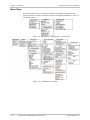
Traffic Flow
Figure 1-4 illustrates the traffic handling process. Table 1-1 provides an overview
of the traffic handling stages.
Traffic Filtering
Traffic
Classification
and Forwarding
Mapping to Queues,
Congestion Avoidance,
Counters
Policing
Egress
Processing and
Shaping
Scheduling
Figure 1-4. Traffic Handling Diagram
Table 1-1. Traffic Handling Stages
Processing Stage
Description
Traffic filtering
Performing MAC filtering (ACL), CE-VLAN filtering, MAC limitation
Traffic classification
Creating EVC or EVC.CoS accrding to CE-VLAN, P-bit
2R3C policing
Applying CIR+CBS,EIR+EBS per EVC/EVC.cos
Mapping to queues,
congestion avoidance,
counters
Mapping EVC/EVC.CoS to 5 queues (1 SPQ + 4 WFQ)
Applying congestion avoidance techniques
Activating counters per EVC/EVC.CoS
Scheduling
Dequeuing traffic from SPQs and WFQs
Egress processing,
egress shaping
Priority (S-Tag) marking
Egress port shaping
Encapsulation
RICi-622GE supports the following encapsulation protocols:
•
Link Access Protocol (LAPS) for SDH/SONET in accordance with
ITU-T Rec. X.86 draft recommendations
•
Generic Framing Procedure (GFP) in accordance with ITU-T Rec. G.7041,
ANSI T1-105.02, framed mode.
LAPS Encapsulation
With LAPS, each Ethernet frame is encapsulated in the frame structure shown in
Figure 1-5. The LAPS frame is delineated by flags, followed by HDLC information
(address and control), and by a LAPS service access point identifier (SAPI). The
Ethernet frame is followed by a LAPS frame checksum (FCS), for error detection.
LAPS Frame
Ethernet Frame
Flag
1-6
HDLC
HDLC
Address Control
LAPS SAPI
Functional Description
Ethernet Frame
LAPS FCS
Flag
RICi-622GE Ver. 1.0
Installation and Operation Manual
(1 byte) (1 byte) (1 byte)
Chapter 1 Introduction
(2 bytes(
(64 to 1500 bytes)
(4 bytes)
(1 byte)
Figure 1-5. LAPS Encapsulation Format
GFP Encapsulation
The GFP encapsulation method uses the basic frame structure shown in
Figure 1-6.
GFP Frame
Ethernet Frame
Core Header
Payload Header
Ethernet Frame
(4 bytes)
(4 bytes)
(1500 bytes)
Figure 1-6. Basic GFP Encapsulation Format
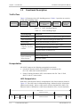
Figure 1-7 shows the detailed structure of a basic GFP frame. The frame includes
the following fields:
•
PLI – Payload length indicator
•
cHEC – Core header CRC (calculated using ITU-T CRC-16 polynomial)
•
Payload Area – Carries a framed PDU
•
Payload Header – Header used for client PDU management
•
pFCS – Optional payload FCS (calculated using ITU-T CRC-32 polynomial).
GFP Frame
Core
Header
Payload
Area
Payload
FCS
PLI
cHEC
Payload Header
Payload Area
pFCS
(16 bits)
(16 bits)
(4 bytes)
(framed PDU – 4 to 65535 bytes)
(32 bits)
Figure 1-7. Detailed Structure of Basic GFP Frame
All GFP OAM&P functions are handled by the GFP core header.
The payload header supports the payload-specific adaptation functions, which
depend on the client application (for RICi-622GE, the client application is
Ethernet). The payload header also supports multiplexing (using extension
headers), and any application-dependent link management functions (using
dedicated client management frames)
Protection against errors (on a per frame basis) is provided by the optional
payload frame checksum (FCS) field.
Idle frames are used for asynchronous rate adaptation.
RICi-622GE Ver. 1.0
Functional Description
1-7
Chapter 1 Introduction
Installation and Operation Manual
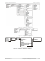
Fault Propagation
Gigabit Ethernet link failure can be propagated over the SDH/SONET link on failure
of one or both links. Also, SDH/SONET link failure can be propagated over the
Gigabit Ethernet link. The user can configure the behavior of the fault
propagation mechanism per Gigabit Ethernet link or SDH/SONET link. Figure 1-8
and Figure 1-9 illustrate the fault propagation mechanism.
Figure 1-8. SDH/SONET to Gigabit Ethernet Fault Propagation
Figure 1-9. SDH/SONET to Gigabit Ethernet Fault Propagation
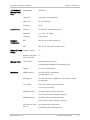
1.4
Gigabit
Ethernet
Interface
STM-4/OC-12
Interface
1-8
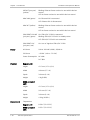
Technical Specifications
Number of Ports
2 (RJ-45 or fiber optic SFPs)
Fiber Optic
Specifications and
Ranges
See SFP Transceivers data sheet for specifications
Electrical Operation
Mode
10/100/1000BaseT, full or half duplex, autonegotiation
Connector
Fiber optic: LC
1000BaseT: RJ-45
Number of Ports
2 (fiber optic SFPs)
Fiber Optic
Specifications and
Ranges
See SFP Transceivers data sheet for specifications
Connector
LC
Technical Specifications
RICi-622GE Ver. 1.0
Installation and Operation Manual
10/100BaseT
Management
Port
Control Port
Standard
Compliance
Compatibility
IEEE 802.3
Operation
Full duplex, autonegotiation
Frame Size
Up to 1500 bytes
Connector
RJ-45
Interface
RS-232/V.24 (DCE asynchronous)
Data Rate
9.6, 19.2, 115.2 kbps
Connector
DB-9, female
IEEE
802.3, 802.3u, 802.1Q, 802.1p
MEF
MEF 9 (EPL, EVPL), MEF 14 (EPL, EVPL)
Ethernet Flows Number of Flows
(EVCs)
Management
Chapter 1 Introduction
16
Number of Services
(EVC or EVC.CoS)
8
Out-of-Band
Via dedicated control port
Via dedicated 10/100BaseT management port
Indicators
Inband
Via user or network port
POWER (green)
On: RICi-622GE is powered on
Off: RICi-622GE is off
RDY (green)
On: RICi-622GE has completed its startup and is ready
for operation
TST (yellow)
On: Test is running such as loopback
Off: No test is running
MAJOR ALM (red)
On: Major alarm condition is present
Off: No major alarm condition is present
MINOR ALM (red)
On: Minor alarm condition is present
Off: No minor alarm condition is present
GbE LINK (per port)
(green)
RICi-622GE Ver. 1.0
On: Ethernet link is connected
Off: Ethernet link is disconnected
Technical Specifications
1-9
Chapter 1 Introduction
GbE ACT (per port)
(yellow)
Installation and Operation Manual
Blinking: Ethernet frame received or sent within the last
second
Off: No frame received or sent within the last second
MNG LINK (green)
On: Ethernet link is connected
Off: Ethernet link is disconnected
MNG ACT (yellow)
Blinking: Ethernet frame received or sent within the last
second
Off: No frame received or sent within the last second
SDH/SONET ON LINE
(per port) (green)
On: STM-4/OC-12 link is connected
Blinking: STM-4/OC-12 link is in standby status
Off: STM-4/OC-12 link is not connected
Power
SDH/SONET LOS
(per port) (red)
On: Loss of signal on STM-4/OC-12 link
AC Source
100 to 240 VAC (±10%), 50/60 Hz
DC Source
–48 VDC (–40 to –72 VDC)
Power Consumption
AC: 40W
DC: 38W
Physical
Regular unit:
Height
43.7 mm (1.7 in) (1U)
Width
440 mm (17.3 in)
Depth
240 mm (9.4 in)
Weight
4 kg (8.8 lb)
NEBS-compliant
unit:
Environment
1-10
Height
43.7 mm (1.7 in) (1U)
Width
541 mm (21.3 in)
Depth
240 mm (9.4 in)
Weight
4.9 kg (10.8 lb)
Temperature
Regular unit:
0–50°C (32–122°F)
NEBS-compliant
unit:
0–55°C (32–131°F)
Technical Specifications
RICi-622GE Ver. 1.0
Installation and Operation Manual
Humidity
RICi-622GE Ver. 1.0
Chapter 1 Introduction
Up to 90%, non-condensing
Technical Specifications
1-11
Chapter 1 Introduction
1-12
Technical Specifications
Installation and Operation Manual
RICi-622GE Ver. 1.0
Chapter 2
Installation and Setup
This chapter describes installation and setup procedures for the RICi-622GE unit.
After installing the unit, refer to Chapter 3 for operating instructions.
If a problem is encountered, refer to Chapter 6 for test and diagnostic
instructions.
Internal settings, adjustment, maintenance, or repairs must be performed only by
a skilled technician who is aware of the hazards involved.
Warning
Warning
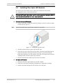
Always observe standard safety precautions during installation, operation, and
maintenance of this product.
For your protection and to prevent possible damage if a fault condition such as a
lightning strike or contact with high voltage power lines occurs on the cables
connected to the equipment, RICi-622GE must be properly grounded at all times.
Any interruption of the protective (grounding) connection inside or outside the
equipment, or disconnection of the protective ground terminal, can make this
equipment dangerous. Intentional interruption is prohibited.
2.1
Site Requirements and Prerequisites
RICi-622GE is intended for installation as a desktop unit, mounted on the wall, or
mounted in a 19-inch rack or 23-inch rack. The following mounting kits are
available from RAD:
•
RM-34 for mounting one 19-inch RICi-622GE unit in a 19-inch rack
•
RM-34-23 for mounting one 23-inch RICi-622GE unit in a 23-inch rack
•
WM-34 for mounting one 19-inch RICi-622GE unit on the wall.
AC-powered RICi-622GE units should be installed within 1.5 meters (5 feet) of an
easily accessible grounded AC outlet capable of furnishing the required supply
voltage, in the range of 100 to 240 VAC, 50/60 Hz.
DC-powered RICi-622GE units require a -48 VDC power source, which must be
adequately isolated from the main supply.
Note
Refer also to the sections describing connections of AC and DC mains at the
beginning of the manual.
Allow at least 90 cm (36 in) of frontal clearance for operator access. For
continuous product operation allow at least 10 cm of frontal clearance and at
RICi-622GE Ver. 1.0
Site Requirements and Prerequisites
2-1
Chapter 2 Installation and Setup
Installation and Operation Manual
least 15 cm at rear of the unit, for cable connections and ventilation. For proper
ventilation, keep at least 4 cm clearance from the sides and top of the product.
The ambient operating temperature of RICi-622GE is 0° to 55° C (32° to 131°F), at
a relative humidity of up to 90%, non-condensing.
Do not cover fan and ventilation openings.
Warning
2.2
Package Contents
RICi-622GE package contains the following items:
•
RICi-622GE unit
•
SFP modules (if ordered)
•
Two AC power cords (for AC option)
•
Two DC connection kits (for DC option)
•
CBL-DB9F-DB9M-STR straight cable for ASCII terminal connection (if ordered)
•
RM-34 (if ordered) for mounting one 19-inch RICi-622GE unit in a
19-inch rack
•
RM-34-23 (if ordered) for mounting one 23-inch RICi-622GE unit in a
23-inch rack
•
WM-34 (if ordered) for mounting one 19-inch RICi-622GE unit on the wall.
2.3
Required Equipment
RICi-622GE requires no special tools for installation. You need a screwdriver to
mount RICi-622GE in a 19-inch or 23-inch rack. You need a screwdriver and drill
to mount RICi-622GE on the wall.
2.4
Mounting the Unit
RICi-622GE is designed for installation as a desktop unit or mounted in a rack.
•
For rack-mounting instructions, refer to the installation kit manual.
•
If RICi-622GE is to be used as a desktop unit, place and secure the unit on a
stable, non-movable surface.
Refer to the clearance and temperature requirements in Site Requirements and
Prerequisites.
2-2
Mounting the Unit
RICi-622GE Ver. 1.0
Installation and Operation Manual
2.5
Chapter 2 Installation and Setup
Installing Fiber Optic SFP Modules
RICi-622GE uses SFP modules with LC fiber optic connectors that provide
hot-swappable industry-standard interfaces.
Third-party SFP optical transceivers must be agency-approved, complying with the
local laser safety regulations for Class 1 laser equipment.
Warning
³
To install fiber optic SFP module:
1. Lock the wire latch of each SFP module by lifting it up until it clicks into place,
as illustrated in Figure 2-1.
Note
Some SFP models have a plastic door instead of a wire latch.
Figure 2-1. Locking the SFP Wire Latch
2. Carefully remove the dust covers from the SFP slot.
3. Insert the rear end of the SFP into the socket, and push slowly backwards to
mate the connectors until the SFP clicks into place. If you feel resistance
before the connectors are fully mated, retract the SFP using the wire latch as
a pulling handle, and then repeat the procedure.
4. Remove the protective rubber caps from the SFP modules.
³
To remove SFP module:
1. Disconnect the fiber optic cables from the SFP module.
2. Unlock the wire latch by lowering it downwards (as opposed to locking).
3. Hold the wire latch and pull the SFP module out of the port.
RICi-622GE Ver. 1.0
Installing Fiber Optic SFP Modules
2-3
Chapter 2 Installation and Setup
2.6
Installation and Operation Manual
Connecting to Gigabit Ethernet Equipment
RICi-622GE includes two Gigabit Ethernet ports.
RICi-622GE is connected to the Gigabit Ethernet equipment via fiber optic SFP or
8-pin RJ-45 electrical port. Refer to Appendix A for the RJ-45 connector pinout.
The Gigabit Ethernet ports must be either both fiber optic interface or both
electrical interface.
³
To connect to the Gigabit Ethernet equipment with fiber optic SFP:
•
Connect RICi-622GE to the Gigabit Ethernet network equipment using a
standard fiber optic cable terminated with an LC connector. Refer to Installing
Fiber Optic SFP Modules for details on installing fiber optic SFPs.
Figure 2-2: Gigabit Ethernet SFP Connectors
³
To connect to the Gigabit Ethernet equipment with a copper interface:
•
Note
Connect RICi-622GE to the Gigabit Ethernet network equipment using a
standard straight UTP/STP cable terminated with an RJ-45 connector.
When connecting Gigabit Ethernet cables longer than 30 meters (98 feet), it is
recommended to use shielded cables.
Figure 2-3: Gigabit Ethernet 10/100/1000BaseT Electrical Connectors
2.7
Connecting to SDH/SONET Equipment
RICi-622GE is connected to the SDH/SONET equipment via fiber optic SFP
interface, with LC connector.
³
To connect to the SDH/SONET network equipment :
•
2-4
Connect RICi-622GE to the SDH/SONET network equipment using a standard
fiber optic cable terminated with an LC connector, as necessary. Refer to
Installing Fiber Optic SFP Modules for details on installing fiber optic SFPs.
Connecting to SDH/SONET Equipment
RICi-622GE Ver. 1.0
Installation and Operation Manual
Chapter 2 Installation and Setup
Figure 2-4: SDH/SONET SFP Connectors
2.8
Connecting to Management Stations
RICi-622GE can be connected to a local ASCII terminal via the CONTROL port or to
a remote network management station via the dedicated Ethernet management
port.
Connecting to an ASCII Terminal
RICi-622GE is connected to an ASCII terminal via a 9-pin D-type female connector
designated CONTROL. Refer to Appendix A for the connector pinout.
³
To connect to an ASCII terminal:
1. Connect the male 9-pin D-type connector of CBL-DB9F-DB9M-STR straight
cable available from RAD to the CONTROL connector.
2. Connect the other connector of the CBL-DB9F-DB9M-STR cable to an ASCII
terminal.
Caution Terminal cables must have a frame ground connection. Use ungrounded cables
when connecting a supervisory terminal to a DC-powered unit with floating
ground. Using improper terminal cable may result in damage to supervisory
terminal port.
Figure 2-5: CONTROL Connector
Connecting to a Network Management Station
RICi-622GE is connected to an NMS via an 8-pin RJ-45 connector designated
ETH MNG. Refer to Appendix A for the connector pinout.
³
To connect to an NMS:
•
Connect RICi-622GE to a hub or switch using a straight cable
or
RICi-622GE Ver. 1.0
Connecting to Management Stations
2-5
Chapter 2 Installation and Setup
•
Note
Installation and Operation Manual
Connect RICi-622GE to a network interface card using a cross cable.
When connecting Fast Ethernet cables longer than 30 meters (98 feet), it is
recommended to use shielded cables.
Figure 2-6: Fast Ethernet Management Connector
2.9
Warning
Connecting to Power
Before connecting or disconnecting any communication cable, the unit must be
grounded by connecting its power cord to a power outlet with a ground terminal,
and by connecting the ground terminal on the panel (if provided) to a protective
ground.
Any interruption of the protective (grounding) conductor (inside or outside the
instrument) or disconnecting of the protective ground terminal can make this
unit dangerous. Intentional interruption is prohibited.
RICi-622GE is equipped with a laser diode.
Please observe the following precautions:
Warning
• Before turning on the equipment, make sure that the fiber optic cable is intact
and is connected to the transmitter.
• Do not look into a laser connector when the power is turned on, a laser can
cause eye damage.
• Do not use broken or unterminated fiber-optic cables/connectors.
ATTENTION: The laser beam may be invisible!
The unit cannot be connected simultaneously to both AC and DC outlets.
Warning
Connecting to AC Power
AC power is supplied to RICi-622GE via 1.5m (5 ft) standard power cable
terminated by standard 3-prong plug. The cable is provided with the unit.
³
To connect AC power:
1. Verify that the AC outlet is grounded properly. Ensure that the supply voltage
is in the range 100 VAC to 240 VAC.
2-6
Connecting to Power
RICi-622GE Ver. 1.0
Installation and Operation Manual
Chapter 2 Installation and Setup
2. Connect the power cable to the power connectors on RICi-622GE first and
then to the AC mains outlet.
Connecting to DC Power
DC-powered RICi-622GE units have one or two terminal block DC inlets.
The -48 VDC power is supplied via connection kits delivered with the unit.
³
To connect DC power:
•
RICi-622GE Ver. 1.0
Refer to the DC power supply connection supplement for instructions how to
wire the DC adapter. The DC supplement is provided at the end of this
manual.
Connecting to Power
2-7
Chapter 2 Installation and Setup
2-8
Connecting to Power
Installation and Operation Manual
RICi-622GE Ver. 1.0
Chapter 3
Operation
This chapter:
•
Explains power-on and power-off procedures
•
Provides a detailed description of the front panel indicators and their
functions
•
Lists methods of RICi-622GE configuration, including working with ASCII
terminal and Web browser management applications
•
Illustrates the menu map.
For a detailed explanation of menu parameters, see Chapter 4.
3.1
³
Turning On the Unit
To power up RICi-622GE:
•
Connect the power cord to the mains.
The POWER indicator lights up and remains lit as long as RICi-622GE
receives power. When the unit has completed its startup procedure and is
ready for operation, the RDY indicator lights up.
RICi-622GE requires no operator attention once installed, with the exception of
occasional monitoring of front panel indicators. Intervention is only required
when RICi-622GE must be configured to its operational requirements, or
diagnostic tests are performed.
3.2
Indicators
The unit's LEDs are located on the front panel and rear panel (see Figure 3-1 and
Figure 3-2). The functions of the RICi-622GE LED indicators are listed in
Table 3-1.
Figure 3-1. RICi-622GE Front Panel
RICi-622GE Ver. 1.0
Indicators
3-1
Chapter 3 Operation
Installation and Operation Manual
Figure 3-2. RICi-622GE Back Panel
Table 3-1. RICi-622GE LEDs
Name
LED Color
Function
POWER
Green
On: RICi-622GE is powered on
Off: RICi-622GE is off
RDY
Green
On: RICi-622GE has completed its startup and is ready for operation
Off: RICi-622GE has not completed its startup or RICi-622GE is off
TST
Yellow
On: Test is running such as loopback
Off: No test is running
MAJOR ALM
Red
On: Major alarm condition is present
Off: No major alarm condition is present
MINOR ALM
Red
On: Minor alarm condition is present
Off: No minor alarm condition is present
GbE LINK 1,2
Green
On: Corresponding Ethernet link is connected
Off: Corresponding Ethernet link is disconnected
GbE ACT 1,2
Yellow
Blinking: Ethernet frame received or sent on corresponding link within the
last second
Off: No frame received or sent on corresponding link within the last second
MNG LINK
Green
On: Ethernet link is connected
Off: Ethernet link is disconnected
MNG ACT
Yellow
Blinking: Ethernet frame received or sent within the last second
Off: No frame received or sent within the last second
SDH/SONET
ON LINE 1,2
Green
On: Corresponding STM-4/OC-12 link is connected
Blinking: Corresponding STM-4/OC-12 link is in standby status
Off: Corresponding STM-4/OC-12 link is not connected
SDH/SONET
LOS 1,2
Red
On: Loss of signal on corresponding STM-4/OC-12 link
3.3
Default Settings
Table 3-2 lists the default settings of the RICi-622GE configuration parameters.
Table 3-2. RICi-622GE Default Settings
Type
Parameter
Default Value
IP Address
0.0.0.0
System
Host
3-2
Default Settings
RICi-622GE Ver. 1.0
Installation and Operation Manual
Type
Chapter 3 Operation
Parameter
Default Value
IP Mask
0.0.0.0
Default Gateway
0.0.0.0
Host Tagging
No
Host VLAN ID
0
Host VLAN Priority
0
SNMP Access
Enable
Telnet/SSH Access
Enable
Web Access
Enable
User Name
None
Permission
None
Server Access
Disable
Server IP Address
0.0.0.0
Key String
Empty
Number of Retries
2
Timeout (in seconds)
2
Authentication Port
1812
Trap Community
public
Write Community
private
Read Community
public
SNMPv3
SNMPv3
Disable
SNMPv3 Settings
Authentication Protocol
usmNoAuthProtocol
Privacy Protocol
usmNoPrivProtocol
Message Processing Model
SNMPv3
Security Model
Any
Security Level
noAuthNoPriv
Baud rate
115,200
Data bits
8
Parity
None
Stop bits
1
Administrative Status
Up
Autonegotiation
Enable
Max Capability Advertised/
Speed & Duplex
SFP installed: 1000BaseX full duplex
RJ-45: 1000BaseT full duplex
Encapsulation
Management Access
User Access
RADIUS Parameters
SNMP
Control Port
Physical Layer
Ethernet
RICi-622GE Ver. 1.0
Default Settings
3-3
Chapter 3 Operation
Type
SDH/SONET
Installation and Operation Manual
Parameter
Default Value
Administrative Status
Up
Block Rx Payload on TIM
Disable
Administrative status
Up
VC Type
SDH : VC-4
SONET: STS-3C
LCAS
No
Number of VCs
4
Encapsulation
GFP
VCAT
Yes
FCS
Yes
Payload Scrambling
Yes
Administrative status
Down
VC Type
Not defined
LCAS
Not defined
Number of VCs
Not defined
Encapsulation
GFP
VCAT
Yes
FCS
Yes
Payload Scrambling
Yes
Usage
User
Accept Frame Type
All
Flow Classification Mode
All-to-One
CoS Profile
DefaultCosPbits1
Default VID
1
Default 802.1p
0
Ingress MTU
2048
Loop detection
Disable
Egress Bandwidth Profile
Default bandwidth profile index (1)
Egress Rate Limit
1,000,000
Egress Burst Size
2048
Usage
User
Accept Frame Type
All
Logical Layer
VCG-1
VCG-2 through VCG-8
Application
Bridge Port (ETH-1)
Bridge Port (ETH-2)
3-4
Default Settings
RICi-622GE Ver. 1.0
Installation and Operation Manual
Type
Bridge Port (VCG-1)
Flows
Bridge Port List
Chapter 3 Operation
Parameter
Default Value
Flow Classification Mode
Flow-Based
CoS Profile
DefaultCosPbits1
Default VID
1
Default 802.1p
0
Ingress MTU
2048
Loop detection
Disable
Egress Bandwidth Profile
Default bandwidth profile index (1)
Egress Rate Limit
1,000,000
Egress Burst Size
2048
Usage
Network
Accept Frame Type
All
Flow Classification Mode
Flow-Based
CoS Profile
DefaultCosPbits1
Default VID
1
Default 802.1p
0
SP Tag Protocol Identifier
8100
Ingress MTU
2048
Marking Profile
Marking1
Loop detection
Disable
Egress Bandwidth Profile
Default bandwidth profile index (1)
Egress Rate Limit
1,000,000
Egress Burst Size
2048
Flow ID
1
Flow Name
Put your string here
Bridge Port
ETH-1
Ingress BW Profile
Profile1
Bridge Port
VCG-1
SP VLAN
0
CoS Profile Name
DefaultCoSPbits1
Tag Value 0
0
Tag Value 1
0
Tag Value 2
0
QoS
CoS Profiles
RICi-622GE Ver. 1.0
Default Settings
3-5
Chapter 3 Operation
Installation and Operation Manual
Type
Marking Profiles
Bandwidth Profiles
3.4
Parameter
Default Value
Tag Value 3
0
Tag Value 4
0
Tag Value 5
0
Tag Value 6
0
Tag Value 7
0
Profile Name
Marking1
CoS Value 0
0
CoS Value 1
0
CoS Value 2
0
CoS Value 3
0
CoS Value 0 for Yellow
0
CoS Value 1 for Yellow
0
CoS Value 2 for Yellow
0
CoS Value 3 for Yellow
0
Profile Name
Profile1
CIR
1000000
CBS
2048
EIR
0
EBS
0
Policed Traffic
All
Color Mode
Blind
Coupling Flag
Disable
Configuration and Management Alternatives
After installation, there are no special operating procedures for RICi-622GE. Once
it is powered up, the unit operates automatically. The unit operational status can
be monitored constantly.
If required, RICi-622GE can be reconfigured. RICi-622GE can be managed using
the following ports and applications:
•
3-6
Local out-of-band management via the Fast Ethernet port or via an ASCII
terminal connected to the RS-232 port. Usually, preliminary configuration of
the system parameters is performed via ASCII terminal. Once the RICi-622GE
host IP parameters are set, it is possible to access it via Telnet, ConfiguRAD,
or RADview Lite for further configuration.
Configuration and Management Alternatives
RICi-622GE Ver. 1.0
Installation and Operation Manual
•
Chapter 3 Operation
Remote inband management via the first user port. Remote management is
performed using Telnet, ConfiguRAD (RAD’s Web-based application), or an
SNMP-based management system).
The RICi-622GE management software supports the following functions:
•
Viewing system information
•
Modifying configuration parameters and modes of operation, including
setting system default values and resetting the unit
•
Monitoring RICi-622GE performance
•
Initiating connectivity tests
•
Uploading and downloading software and configuration files.
Working with Terminal
RICi-622GE has a V.24/RS-232 asynchronous DCE port, designated CONTROL and
terminated in a 9-pin D-type female connector. The control port continuously
monitors the incoming data stream and immediately responds to any input string
received through this port.
The RICi-622GE control port can be configured to communicate at the following
rates: 9.6, 19.2, or 115.2 kbps.
³
To start a terminal control session:
1. Make sure all RICi-622GE cables and connectors are properly connected.
2. Connect RICi-622GE to a PC equipped with an ASCII terminal emulation
application (for example, Windows Hyper Terminal or Procomm).
3. Turn on the control terminal PC and set its port parameters to:
115,200 baud, 8 bits/character, 1 stop bit, no parity, flow control: none.
4. Set the terminal emulator to ANSI VT100 emulation (for optimal view of
system menus).
5. If you are using Hyper Terminal, set the terminal mode to 132 column mode
for optimal view of system menus
(Properties->Settings->Terminal Setup->132 column mode).
6. When the initialization and self-test are over, press any key to display the
login screen.
RICi-622GE
USER NAME:
PASSWORD:
ESC – clear; & – exit;
0 M/2 C
Figure 3-3. Login Screen
RICi-622GE Ver. 1.0
Configuration and Management Alternatives
3-7
Chapter 3 Operation
Installation and Operation Manual
Logging In
To prevent unauthorized modification of operating parameters, RICi-622GE
supports two access levels:
Note
³
•
Superuser can perform all the activities supported by the RICi-622GE
management facility, including defining new users.
•
User’s access rights are defined by the superuser. Users are not allowed to
create new users.
It is recommended to change default passwords to prevent unauthorized access
to the unit.
To enter as a superuser:
1. Enter su for user name.
2. Enter 1234 for password.
This allows you to configure all the parameters of RICi-622GE, and to change the
su and user passwords.
³
To enter as a user:
1. Enter user for user name.
2. Enter 1234 for password.
Choosing Options
This section describes how to work with the menus provided by the RICi-622GE
management software.
³
To select a menu item:
•
Type the corresponding line number and then press <Enter>.
One of the following occurs:
•
3-8
A submenu or parameter selection screen is displayed
You are enabled to type the (free text) parameter value in the same
row
You are enabled to toggle the current value of the corresponding
parameter (relevant to ENABLE/DISABLE or ON/OFF selections).
The response received after selecting a menu item is indicated as follows:
>
Selecting that item displays a submenu or a parameter selection
screen.
...
Selecting that item enables you to type the desired value in the
same line.
Nothing
When neither symbol is displayed, selecting that item toggles
the current selection, now shown in brackets (for example, this
changes ENABLE to DISABLE or vice versa).
Configuration and Management Alternatives
RICi-622GE Ver. 1.0
Installation and Operation Manual
Chapter 3 Operation
Parameter Selection Screen
The current value of a parameter is listed within parentheses ( ).
³
To change a parameter value on a parameter selection screen:
•
³
Type the line number corresponding to the desired value, and then press
<Enter>.
To enter a value that requires free text entry
•
Type in the desired string and then press <Enter>. Use backspace to erase
the current string.
Note that when applicable, the allowed range of values of a parameter is
listed within square brackets [ ].
The entry is checked after pressing <Enter>, and it is accepted only if it is
valid:
If you make an error, for example, if you press a key not active on the current
screen or select an invalid parameter value, an ERROR indicator appears in the
right-hand corner. This indicator disappears as soon as you perform a correct
operation.
If you select a parameter value incompatible with the current operating state or
other parameters, a message is displayed that explains the error.
Terminal Hot Keys
The available hot keys are listed in the lower part of each screen. The following
hot keys are system keys available on menu screens:
•
<Esc> – Return to previous menu
•
<Tab> – select the next cell that may be changed
•
A or a – Add item
•
S or s – Save
•
D or d – Delete, for example to delete an item from the Data Base
•
! – Return to the main menu
•
& – Exit to password screen (to prevent unauthorized access after completing
the session)
•
F or f – Forward interval (statistic menus)
•
B or b – Backward interval (statistic menus).
When a menu is too long to fit on one screen, it is displayed on two consecutive
pages. In this case, you see …(N) after the last line on the first page and …(P)
after the last line on the second page.
³
To navigate between the pages:
•
While on the first page, press N to display the second page
•
While on the second page, press P to return to the first page.
When a configuration screen is organized as a table, a special set of keys is used
for navigation within the table (this type of screen always has a ? (help) option
RICi-622GE Ver. 1.0
Configuration and Management Alternatives
3-9
Chapter 3 Operation
Installation and Operation Manual
that displays these keys). The following keys and shortcuts are available for
navigation within tables:
•
<Left arrow> – move left
•
<Right arrow> – move right
•
<^L > – scroll left
•
<^R > – scroll right
•
^D – scroll down
•
^U – scroll up
•
<Tab> – select next changeable cell
•
G followed by <row number>,<col number> – select a specific cell. For
example, type G2,5 to select the fifth cell in the second row.
Ending a Terminal Configuration Session
³
To end the current terminal session:
•
Type &.
After a session is ended, you must log in with a valid user name and password to
start a new session.
Working with ConfiguRAD
Web Browser Requirements
The following Web browsers can be used to access the RICi-622GE supervision
utility from any location that enables access to the RICi-622GE using Internet
protocols.
•
Internet Explorer 6.0 and up, running on Windows™
•
Netscape Communicator 7.0 and up, running on Windows™, HPOV, or Linux
•
Firefox 1.0.4 and up, running on Windows™
•
Mozilla 1.4.3 and up, running on Linux.
it is necessary to configure RICi-622GE for Web access before it can be accessed
with a Web Browser.
When using a Web browser, pay attention to the following points:
3-10
•
Enable scripts
•
Configure the firewall that is probably installed on your PC to allow access to
the destination IP address
•
Disable pop-up blocking software (such as Google Popup Blocker); you may
also have to configure your spyware/adware protection program to accept
traffic from/to the destination IP address
•
Flush the browser’s cache whenever you return to the same screen. This is
necessary to prevent configuration errors, because browsers store the last
viewed pages in a special cache.
Configuration and Management Alternatives
RICi-622GE Ver. 1.0
Installation and Operation Manual
Chapter 3 Operation
Logging In
³
To manage RICi-622GE via Web browser:
1. Open the Web browser.
2. Enter the IP address of RICi-622GE in the address field of the browser in the
following format: http://’IP address’ (‘IP address’ stands for the actual
RICi-622GE IP address).
3. After entering the address, press <Enter> to command the browser to
connect.
4. After the opening window is displayed, click LOGIN.
5. In the Password Entry window, log in by entering your user name (user) and
password (1234).
The Main menu is displayed.
6. Use standard browser operating procedures to perform the desired activities.
Notes
• It is recommended to change default passwords to prevent unauthorized
access to the unit.
• If no user input is detected during a ConfiguRAD session for the amount of
time defined by the security timeout parameter in the Terminal menu, the
RICi-622GE unit automatically disconnects from the management station. After
the unit disconnects, the system doesn’t react to user input.
Navigating the ConfiguRAD Menus
ConfiguRAD is Web-based remote access terminal management software. It
provides a user-friendly interface for configuring, collecting statistics, and
performing diagnostic tests on RICi-622GE.
³
To choose an option:
1. Click a link in the ConfiguRAD screen to display the next menu.
2. When the target screen is displayed, select a value from the drop-down box
or enter it in a text box.
At the left-hand bottom corner, ConfiguRAD provides some auxiliary management
tools:
RICi-622GE Ver. 1.0
•
Status – shows the number of users currently managing RICi-622GE
•
Trace – opens an additional pane for system messages, progress indicators
(ping, software and configuration file downloads), and alarms. It is
recommended to always keep the trace pane open.
•
Refresh All – refreshes all ConfiguRAD display elements.
Configuration and Management Alternatives
3-11
Chapter 3 Operation
Installation and Operation Manual
Menu Maps
Use these menu trees as a reference aid while performing configuration and
control functions. Chapter 4 illustrates menus and explains parameters. Table 3-2
lists default values.
Figure 3-4. Main Menu > Configuration > Quick Setup
Figure 3-5. Configuration > System
3-12
Configuration and Management Alternatives
RICi-622GE Ver. 1.0
Installation and Operation Manual
Chapter 3 Operation
Figure 3-6. Configuration > Physical Layer
Figure 3-7. Configuration > Logical Layer
Configuration
Quick Setup
System
Physical Layer
Logical Layer
Application
Application
Bridge
QoS
Flows
Bridge
Bridge Port
Bridge Port
Usage
Accept Frame Type
Flow Classification Mode
Flow Key
CoS Profile
Default VID
Default 802.1p
Egress Action (network port only)
SP Tag Protocol Identifier (network port only)
Ingress MTU
Marking Profile (network port only)
L2CP Handling
Egress Bandwidth Profile
Egress Bandwidth Profile
CoS
Egress Rate Limit
Egress Burst Size
Figure 3-8. Configuration > Application > Bridge Port
RICi-622GE Ver. 1.0
Configuration and Management Alternatives
3-13
Chapter 3 Operation
Installation and Operation Manual
Configuration
Quick Setup
System
Physical Layer
Logical Layer
Application
QoS
Bridge
QoS
Flows
CoS Profiles
Marking Profiles
Bandwidth Profiles
CoS Profiles
Ingress Priority Method
Profile Name
CoS Mapping
Marking Profiles
Profile Name
Marking
Bandwidth Profiles
Profile Name
CIR
CBS
EIR
EBS
Policed Traffic
Color Mode
Coupling Flag
Figure 3-9. Configuration > Application > QoS
Configuration
Quick Setup
System
Physical Layer
Logical Layer
Application
Flows
Bridge
QoS
Flows
Flow Name
Bridge Port List
Bridge Port List
SP VLAN
Mapping
Marking
Marking Value
Ingress Bandwidth Profile
Services
Fixed CoS
Egress VLAN Preservation Mode
Mapping
Flow ID
Mapping Mode
CE-VLAN ID Members/
SP-VLAN ID Members
Figure 3-10. Configuration > Application > Flows
Figure 3-11. Monitoring, Diagnostics
3-14
Configuration and Management Alternatives
RICi-622GE Ver. 1.0
Installation and Operation Manual
3.5
³
Turning Off the Unit
To power off the unit:
•
RICi-622GE Ver. 1.0
Chapter 3 Operation
Remove the power cord from the power source.
Turning Off the Unit
3-15
Chapter 3 Operation
3-16
Turning Off the Unit
Installation and Operation Manual
RICi-622GE Ver. 1.0
Chapter 4
Configuration
This chapter illustrates the configuration RICi-622GE screens and explains their
parameters. The menu tree of the RICi-622GE management software is shown in
Chapter 3.
For your convenience, parameters that are mandatory for configuration, such as
RICi-622GE host IP settings, are located in the Quick Setup menu (Main menu >
Configuration > Quick Setup). This menu is explained in the Quick Start Guide at
the beginning of the manual, and the menu parameters are explained in the
relevant sections of this chapter.
4.1
Configuring RICi-622GE for Management
Usually, initial configuration of the management parameters is performed via
ASCII terminal. Once the RICi-622GE host IP parameters are set, it is possible to
access it via Telnet, ConfiguRAD, or SNMP-based management system for
operation configuration.
Perform the following steps to configure RICi-622GE for management:
•
Defining Host IP Parameters
•
Entering Device Information
•
Configuring Host Encapsulation
•
Controlling Management Access
•
Configuring User Access
•
Configuring Network Managers
•
Configuring SNMPv3
•
Configuring RADIUS Client
•
Configuring Control Port Parameters.
Defining Host IP Parameters
RICi-622GE can be managed by a network management station that is located on
the LAN connected to the unit’s network or first user port, or out-of-band Fast
Ethernet management port. In order to establish a proper connection, it is
necessary to define the host IP address, subnet mask, and default gateway.
RICi-622GE Ver. 1.0
Configuring RICi-622GE for Management
4-1
Chapter 4 Configuration
³
Installation and Operation Manual
To define the host IP parameters:
•
From the Host menu (Configuration > System > Management> Host), perform
the following:
Select IP Address to define the host IP address
Select IP Mask to define the host IP mask
Select Default Gateway to enter the default gateway IP address.
Note
The default gateway must be in the same subnet as the host.
If SNMPv3 is not enabled, then in order to establish a proper SNMP management
link, you must specify the read community, write community, and trap
community. These community parameters are in the menu only if SNMPv3 is not
enabled.
³
To configure RICi-622GE communities:
•
From the Host menu (Configuration > System > Management> Host), do the
following:
Select Read community to enter the name of a community with read-only
authorization (up to 20 alphanumeric characters, case sensitive).
Select Write community to enter the name of a community with write
authorization (up to 20 alphanumeric characters, case sensitive).
Select Trap community to enter the name of a community to which
RICi-622GE sends traps (up to 20 alphanumeric characters, case sensitive).
Note
You must assign different names to the Read and Write communities.
RICi-622GE
Configuration>System>Management>Host
1.
2.
3.
4.
5.
6.
7.
IP address
IP mask
Default Gateway
Read community
Write community
Trap community
Encapsulation
...
...
...
...
...
...
(0.0.0.0)
(0.0.0.0)
(0.0.0.0)
(public)
(private)
(public)
>
>
ESC-prev. menu; !-main menu; &-exit
1 M/2 C
Figure 4-1. Host Menu, SNMPv3 not enabled
4-2
Configuring RICi-622GE for Management
RICi-622GE Ver. 1.0
Installation and Operation Manual
Chapter 4 Configuration
RICi-622GE
Configuration>System>Management>Host
1.
2.
3.
4.
IP address
IP mask
Default Gateway
Encapsulation
... (0.0.0.0)
... (0.0.0.0)
... (0.0.0.0)
>
>
ESC-prev. menu; !-main menu; &-exit
1 M/2 C
Figure 4-2. Host Menu, SNMPv3 enabled
Entering Device Information
The RICi-622GE management software allows you to assign a name to the unit,
specify its location to distinguish it from the other devices installed in your
system, and assign a contact person.
³
To enter device information:
1. From the Device Information menu (Configuration > System > Management >
Device Information), select Name and enter a name for the RICi-622GE unit.
2. Select Location and enter the name for the current RICi-622GE location.
3. Select Contact and enter the name of a contact person.
RICi-622GE
Configuration>System>Management>Device Information
Description
... RICi-622GE
1. Name
2. Location
3. Contact
... (RICi-622GE)
... (The Location of the Device)
... (Name of Contact Person)
>
ESC-prev.menu; !-main menu; &-exit
1 M/2 C
Figure 4-3. Device Info Menu
Configuring Host Encapsulation
RICi-622GE management software allows you to create a dedicated management
VLAN in order to separate management traffic from the user data.
³
To configure the host encapsulation:
•
RICi-622GE Ver. 1.0
From the Encapsulation menu (Configuration > System > Management> Host
> Encapsulation), do the following:
Configuring RICi-622GE for Management
4-3
Chapter 4 Configuration
Installation and Operation Manual
Select Host Tagging, and choose Yes or No to consider or ignore the VLAN
tagging of the management traffic coming from the management station.
If host tagging is enabled:
Select Host VLAN ID and define the ID of the host VLAN (1–4094)
Select Host Priority Tag and define the priority of the host VLAN (0–7).
If host tagging is disabled:
Select SP Management VLAN ID and define the VID for management
traffic towards the SP network (1–4094).
Select SP Management Priority Tag and define the VLAN priority for
management traffic towards the SP network (0–7).
Select Security Definition and define the network/user ports from which
the manager can access RICi-622GE. Possible values are:
All – RICi-622GE can be accessed via any of its ports
SDHSONET Only – RICi-622GE can be accessed via only SDH/SONET port
and Fast Ethernet management port
GBE Only – RICi-622GE can be accessed via only Gigabit Ethernet port
and Fast Ethernet management port
None – RICi-622GE can be accessed via only Fast Ethernet management
port.
RICi-622GE
Configuration>System>Management>Host>Encapsulation
1.
2.
3.
4.
Host Tagging
Host VLAN ID [1 - 4094]
Host Priority Tag [0 - 7]
Security Definition
(Yes)
... (300)
... (7)
> (All)
>
ESC-prev.menu; !-main menu; &-exit
1 M/2 C
Figure 4-4. Encapsulation Menu, Host Tagging Enabled
RICi-622GE
Configuration>System>Management>Host>Encapsulation
1.
2.
3.
4.
Host Tagging
(No)
SP Management VLAN ID [1 - 4094]
... (300)
SP Management Priority Tag [0 - 7] ... (7)
Security Definition
... (All)
>
ESC-prev.menu; !-main menu; &-exit
1 M/2 C
Figure 4-5. Encapsulation Menu, Host Tagging Disabled
4-4
Configuring RICi-622GE for Management
RICi-622GE Ver. 1.0
Installation and Operation Manual
Chapter 4 Configuration
Controlling Management Access
You can enable or disable access to the RICi-622GE management system via SNMP,
Telnet, or Web-based application. If SNMP, Telnet, and Web access is disabled,
RICi-622GE can be managed only via an ASCII terminal. In addition, you can limit
access to RICi-622GE to only the stations defined in the manager list.
³
To define the management access method:
1. From the Management Access menu (Configuration > System > Management
> Management Access):
Select Telnet/SSH Access to configure Telnet access
Select SNMP to configure SNMP access
Select Web to configure Web access.
2. Define the access mode for the selected management method:
Enable – selected management method is enabled
Disable – selected management method is disabled.
Enable Secure (not relevant for SNMP):
SSH-enabled secure access for Secure Shell is enabled if management
method is Telnet/SSH
SSL-enabled secure access for Web is enabled if management method
is Web Access.
RICi-622GE
Configuration>System>Management>Management Access
1.
2.
3.
4.
5.
6.
User Access
Telnet/SSH access
WEB
SNMP
Radius Authentication
RADIUS Parameters
>
>
>
>
>
>
(Disable)
(Enable)
(Enable)
(Enable Remote)
>
ESC-prev.menu; !-main menu; &-exit
1 M/2 C
Figure 4-6. Management Access Menu
Configuring User Access
RICi-622GE allows the definition of new users and their access levels. Only
superusers can define new users, while regular users can change their passwords.
³
To add a new user:
1. Make sure that you are logged in as su.
2. From the Management Access menu (Configuration > System > Management
> Management Access), select User Access.
RICi-622GE Ver. 1.0
Configuring RICi-622GE for Management
4-5
Chapter 4 Configuration
Installation and Operation Manual
The User Access menu is displayed (see Figure 4-7).
3. From the User Access menu, do the following:
Select User name, and enter a name for a new user.
Select Permission, and specify the user’s access rights (full control or read
only).
Select Access, and specify the user’s access methods (Terminal,
Telnet/SSH, Web, Telnet and Web, or all of them).
Select ‘su’ password, and enter your current superuser password.
Select New password, and assign a password to a new user name.
Select Confirm and re-enter the new user password to confirm it.
³
To delete an existing user:
•
From the User Access menu, do the following:
Type F to display a user that you intend to delete.
Select ‘su’ password, and enter your current superuser password.
Type D to delete the current user.
RICi-622GE
Configuration>System>Management>Management Access>User Access
1.
2.
3.
4.
5.
6.
User name
Permission
Access
‘su’ password
New password
Confirm New Password
...
>
>
...
...
...
(su)
(Full Control)
(All)
()
()
()
>
Please select item <1 to 6>
ESC-prev.menu; !-main menu; &-exit
1 M/2 C
Figure 4-7. User Access Menu
Configuring Network Managers
You can configure up to 10 network managers to which the RICi-622GE SNMP
agent sends traps. In addition, you can temporarily prevent a manager station
from receiving traps by masking the network manager.
³
To configure network managers:
•
From the Manager List menu (Configuration > System > Management >
Manager List), do the following in the manager list table entry:
Select IP address and enter the IP address
Select Trap and configure to the appropriate value:
4-6
Masked –All alarm traps are masked
Configuring RICi-622GE for Management
RICi-622GE Ver. 1.0
Installation and Operation Manual
Chapter 4 Configuration
Unmasked – All alarms are enabled. The manager is informed of the
occurrence of any alarm (entry or exit to/from alarm state).
RICi-622GE
Configuration>System>Management>Manager list
Num
IP address
Trap
1
198.25.6.2
(Unmasked)
2
0.0.0.0
(Unmasked)
3
0.0.0.0
(Unmasked)
4
0.0.0.0
(Unmasked)
5
0.0.0.0
(Unmasked)
6
0.0.0.0
(Unmasked)
7
0.0.0.0
(Unmasked)
8
0.0.0.0
(Unmasked)
9
0.0.0.0
(Unmasked)
10
0.0.0.0
(Unmasked)
>
ESC-prev. menu; !-main menu; &-exit
1 M/2 C
Figure 4-8. Manager List Menu
Configuring SNMPv3
RICi-622GE supports the SNMP version 3 entity, providing secure access to the
device by authenticating and encrypting packets transmitted over the network.
When SNMPv3 is disabled, RICi-622GE supports SNMPv1.
Follow these steps to configure the SNMPv3 entity:
1. Enable SNMPv3.
2. Add a new user.
3. Add a new notification entry.
4. Assign traps to notification entries.
5. Configure target (NMS) parameters.
6. Specify the target address, define its parameter set, and assign notification
tags.
7. Map SNMPv3 settings to SNMPv1 settings (if necessary).
Enabling SNMPv3
The SNMPv3 entity is enabled from the Management menu.
³
To enable SNMPv3:
1. From the Management menu (Configuration > System > Management), select
SNMPv3 and enable the SNMPv3 entity.
RICi-622GE Ver. 1.0
Configuring RICi-622GE for Management
4-7
Chapter 4 Configuration
Installation and Operation Manual
2. Type S to save your changes.
A confirmation message appears.
CURRENT CONFIGURATION OF SNMP AGENT WILL BE DELETED! CONTINUE? (Y/N)
3. Type Y to confirm or N to cancel.
If you type Y, SNMPv3 is enabled and the SNMPv3 Settings line appears in
the Management menu.
³
To configure SNMPv3:
1. From the Management menu (Configuration > System > Management), select
SNMPv3 Settings.
The SNMPv3 Settings menu appears (see Figure 4-9).
The SNMPv3 Settings menu includes the following information:
Engine Boots (The number of times that the SNMP engine has reinitialized
since its identification was last configured.)
Engine Time (The number of seconds since the last SNMP engine boot)
SNMP Message Size (The maximum length of an SNMP message (in octets)
that the SNMP engine can send or receive and process.)
RICi-622GE
Configuration>System>Management>SNMPv3 Settings
1.
2.
3.
4.
5.
6.
Engine Boots
Engine Time
SNMP Message Size
Users
Targets & Notify
SNMPv1/v3 Mapping
SNMPv3 Factory Defaults
Summary User Table
Summary Target Table
(4)
(10044)
... (1500)
>
>
>
[]
[]
>
ESC-prev.menu; !-main menu; &-exit
1 M/2 C
Figure 4-9. SNMPv3 Settings Menu
Adding SNMPv3 Users
³
To add an SNMPv3 user:
1. From the SNMPv3 Users menu (Configuration > System > Management >
SNMPv3 Settings > Users), perform the following:
Select Security Name and enter security name for a new user (up to 32
alphanumeric characters).
4-8
Configuring RICi-622GE for Management
RICi-622GE Ver. 1.0
Installation and Operation Manual
Chapter 4 Configuration
Select Authentication Protocol and define the authentication protocol to
be used for authenticating the user:
usmNoAuthProtocol (No authentication is performed)
usmHMACMD5AuthProtocol (MD5 protocol)
usmHMACSHAAuthProtocol (SHA protocol).
Select Privacy Protocol and define the type of privacy protocol to be used
for encryption:
usmNoPrivProtocol (Privacy protocol is not used)
usmDESPrivProtocol (DES protocol).
Select Authentication Password and define the authentication password of
the user. This is not available if authentication has been disabled.
Select Privacy Password and define the private key used for encryption.
This is not available if privacy has been disabled.
2. To view the summary of the SNMPv3 user configuration, select Summary User
Table from the SNMPv3 Settings menu (Configuration > System >
Management > SNMPv3 Settings).
³
To delete an SNMPv3 user:
1. From the Users menu (Configuration > System > Management > SNMPv3
Settings > Users), type f or b to select an SNMPv3 user.
2. Type r to delete the selected user.
Adding Notification Entries
³
To add a notification entry:
1. From the Targets and Notify menu (Configuration > System > Management >
SNMPv3 Settings > Targets & Notify), select Notify.
The Notify menu appears (see Figure 4-11).
2. From the Notify menu, do the following:
Select Name and enter an ASCII string identifying the notification entry
Select Type and enter the type of notification entry
Select Tag and enter a tag value to be associated with the notification
entry. This tag is used to identify the current notification entry when
configuring the target address.
RICi-622GE Ver. 1.0
Configuring RICi-622GE for Management
4-9
Chapter 4 Configuration
Installation and Operation Manual
RICi-622GE
Configuration>System>Management> SNMPv3 Settings> Targets & Notify
1.
2.
3.
4.
Target Params
Target Address
Notify
Trap
...()
...()
...()
...()
>
ESC-prev.menu; !-main menu; &-exit
1 M/2 C
Figure 4-10. Targets & Notify Menu
RICi-622GE
Configuration>System>Management> SNMPv3 Settings> Targets and Notify > Notify
5. Name
6. Type
7. Tag
...()
...()
...()
>
ESC-prev.menu; !-main menu; &-exit
1 M/2 C
Figure 4-11. Notify Menu
Assigning Traps
One or more traps must be assigned to each notification entry.
³
To assign traps to notification entries:
•
From the Trap menu (Configuration > System > Management > SNMPv3
Settings > Targets & Notify >Trap), do the following:
Select Notify Name and enter a tag from the list of previously defined
notification tags)
Select Trap Name and enter a trap to be assigned to the selected tag.
RICi-622GE
Configuration>System>Management> SNMPv3 Settings> Targets and Notify > Trap
1. Notify Name
2. Trap Name
>()
>()
>
ESC-prev.menu; !-main menu; &-exit
1 M/2 C
Figure 4-12. Trap Menu
Configuring Target Parameters
The SNMPv3 network management station to which RICi-622GE sends trap
notifications is referred to as a target. A set of parameters must be configured
and assigned to each target.
4-10
Configuring RICi-622GE for Management
RICi-622GE Ver. 1.0
Installation and Operation Manual
³
Chapter 4 Configuration
To configure target parameters:
•
From the Target Params menu (Configuration > System > Management >
SNMPv3 Settings > Targets and Notify > Target Params), do the following:
Select Name and enter an ASCII string identifying the current set of target
parameters
Select Message Processing Model and enter the Message Processing Model
to be used when generating SNMP messages using this entry:
SNMPv1
SNMPv2c
SNMPv2u
SNMPv3.
Select Security Model and enter the Security Model to be used when
generating SNMP messages using this entry:
Any
SNMPv1
SNMPv2c
User-Based Security Model (USM).
Select Security Name and enter identification of the principal on whose
behalf SNMP messages are to be generated using this entry. This can be
either SNMPv3 user or SNMPv1/SNMPv2 community string.
Select Security Level and enter the level of security to be used when
generating SNMP messages using this entry:
noAuthNoPriv – Authorization and privacy are disabled
authNoPriv – Authorization is enabled, privacy is disabled)
authPriv – Authorization and privacy are enabled.
RICi-622GE
Configuration>System>Management> SNMPv3 Settings> Targets and Notify > Target
Params
1.
2.
3.
4.
5.
Name
Message Processing Model
Security Model
Security Name
Security Level
...
>
>
...
>
()
()
()
()
()
>
ESC-prev.menu; !-main menu; &-exit
1 M/2 C
Figure 4-13. Target Params Menu
RICi-622GE Ver. 1.0
Configuring RICi-622GE for Management
4-11
Chapter 4 Configuration
Installation and Operation Manual
Configuring Target Address
Each target must have a valid IP address. Also, a previously configured parameter
set and notification tags must be assigned to the target.
³
To configure the target address:
1. From the Target Address menu (Configuration > System > Management >
SNMPv3 Settings > Targets and Notify > Target Address), do the following:
Select Name and enter an ASCII string identifying the target
Select IP Address and enter valid IP address of the NMS. The IP address
must be in xxx.xxx.xxx.xxx:162 format, where 162 is a standard SNMP port
used for sending traps.
Select Params Name and enter name of the previously defined target
parameter set to be assigned to this target
Select Tag List and enter list of previously defined notification tags.
2. To view the summary of the SNMPv3 target configuration, select Summary
Target Table from the SNMPv3 Settings menu (Configuration > System >
Management > SNMPv3 Settings).
RICi-622GE
Configuration>System>Management>SNMPv3 Settings>Targets and Notify>Target Address
1.
2.
3.
4.
Name
IP Address
Params Name
Tag List
...
...
...
...
()
()
()
()
>
ESC-prev.menu; !-main menu; &-exit
1 M/2 C
Figure 4-14. Target Address Menu
Mapping SNMPv1 to SNMPv3
RICi-622GE supports coexistence of different SNMP versions by mapping
SNMPv1/SNMPv2 community name to the SNMPv3 security name value. The
mapping is performed according to the requirements in RFC 3587.
³
To map SNMPv1 to SNMPv3:
•
From the SNMPv1/v3 Mapping menu (Configuration > System > Management
> SNMPv3 Settings > SNMPv1/v3 Mapping), do the following:
Select Community Index and enter SNMP community index
Select Community String and enter SNMPv1/SNMPv2 community name
Select Security Name and enter SNMPv3 security name mapped to the
SNMPv1/SNMPv2 community name
Select Transport Tag and enter a set of transport endpoints that are used
in two ways:
4-12
Configuring RICi-622GE for Management
RICi-622GE Ver. 1.0
Installation and Operation Manual
Chapter 4 Configuration
To specify the transport endpoints from which an SNMP entity accepts
management requests
To specify the transport endpoints to which a notification may be sent
using the community string matching the corresponding instance of
community name.)
RICi-622GE
Configuration>System>Management>SNMPv3 Settings>SNMPv1/v3 Mapping
1.
2.
3.
4.
Community Index
Community Name
Security Name
Transport Tag
...
...
...
...
()
()
()
()
>
ESC-prev.menu; !-main menu; &-exit
1 M/2 C
Figure 4-15. SNMPv1/v3 Mapping Menu
Returning to SNMPv3 Factory Defaults
The SNMPv3 factory default option allows you to reset the SNMPv3 parameters to
factory default values.
³
To return to SNMPv3 factory default values:
1. From the SNMPv3 Settings menu (Configuration > System > Management >
SNMPv3 Settings), select SNMPv3 Factory Defaults.
A confirmation message appears.
THE SNMPV3 SETUPS WILL REINITIALIZE. DO YOU WANT TO PROCEED? (Y/N)
2. Type Y to confirm or N to cancel.
If you type Y, the device is reset to SNMPv3 factory default values.
Configuring RADIUS Client
The RADIUS (Remote Authentication Dial-In User Service) is a client/server
security protocol. Security information is stored in a central location, known as
the RADIUS server. RADIUS clients, such as RICi-622GE, communicate with the
RADIUS server to authenticate users. RICi-622GE supports up to four RADIUS
servers.
³
To configure the RADIUS client:
1. From the RADIUS Parameters menu (Configuration > System > Management >
Management Access > RADIUS Parameters), type f to select a RADIUS server
that you intend to configure.
The Server Status parameter indicates the current status of the selected
server. The status is one of the following:
Connected – Selected server is currently operating as an active RADIUS
server
RICi-622GE Ver. 1.0
Configuring RICi-622GE for Management
4-13
Chapter 4 Configuration
Installation and Operation Manual
Not Connected – Selected server is a backup RADIUS server
Disconnected – Connection to the selected server has timed out.
2. Configure the following parameters:
Server Access – Disables or enables the RADIUS server
Server IP Address – IP address of the RADIUS server.
Key String – The shared secret is a password used by RADIUS to
authenticate the client. RICi-622GE encrypts the user-password, if present;
using the secret it shares with the RADIUS server. Any alphanumeric string
up to 16 characters is permitted.
Number of retries – The number of retries to be made when sending
request to the RADIUS server): Permitted values are 0–5.
Timeout – The maximum time RICi-622GE waits for a single request
response from the RADIUS server (in seconds). After this time the request
is retransmitted.): Permitted values are 0–60.
Authentication Port – The UDP port number to be used for the RADIUS
authentication application. You must define the same value in the RADIUS
server.): any valid UDP port number.
RICi-622GE
Configuration>System>Management>Management Access>Radius Parameters
1.
2.
3.
4.
5.
6.
Server Sequence Number
Server Status
Server access
Server IP address
Key String
Number of Retries [0-10]
Timeout (in seconds) [1-5]
Authentication Port [1-65535]
(1)
(Not connected)
(Enable)
(172.17.150.71)
(******)
(3)
(2)
(1812)
>
ESC-prev.menu; !-main menu; &-exit
1 M/2 C
Figure 4-16. Radius Parameters Menu
³
To configure RADIUS operation mode:
•
From the Management Access menu (Configuration > System > Management
> Management Access), select RADIUS Authentication and select one of the
authentication modes:
Disable – RADIUS authentication is disabled
Enable Remote – RICi-622GE uses authentication database stored at the
RADIUS server to check if the entered user name and password match the
data server records. User authentication fails if one the following occurs:
4-14
No user name record is found
Password does not match user name
Connection to the RADIUS server is lost.
Configuring RICi-622GE for Management
RICi-622GE Ver. 1.0
Installation and Operation Manual
Note
Chapter 4 Configuration
Special rules apply to the su (superuser) user name. If connection to the RADIUS
server is lost, RICi-622GE uses its internal authentication database for the user
verification and allows login for the superuser.
Enable Remote Local – RICi-622GE uses authentication database stored at
the RADIUS server to check if the entered user name and password match
the data server records. If no user name record is found or a password
does not match user name, RICi-622GE uses its internal authentication
database.
Note
You must set the RADIUS server IP address in the RADIUS parameters menu
before you can enable RADIUS authentication.
Configuring Control Port Parameters
RICi-622GE management software allows you to configure the control port
parameters, which include specifying the terminal data rate, data bits, parity,
stop bits, and security timeout.
³
To configure the control port parameters:
•
From the Control Port menu (Main > Configuration > System > Control Port),
do the following:
•
Select Baud Rate to specify the data rate (permitted values are 9600 bps;
19,200 bps; or 115,200 bps).
•
Select Data bits to specify the data bits (7 or 8)
•
Select Parity to specify the parity (None, Odd, or Even)
•
Select Stop Bits to specify the stop bits (NA, 1, 1.5, or 2)
•
Select Terminal and then Security Timeout to specify the number of minutes
to keep a ConfiguRAD or Terminal session active when there is no user input
(1–60).
RICi-622GE
Configuration>System>Control Port
1.
2.
3.
4.
5.
>
Set Baud Rate (Bps)
Data bits
Parity
Stop bits
Terminal
>
>
>
>
>
(115200 bps)
(8)
(None)
(1)
ESC-prev. menu; !-main menu; &-exit
1 M/2 C
Figure 4-17. Control Port Menu
RICi-622GE Ver. 1.0
Configuring RICi-622GE for Management
4-15
Chapter 4 Configuration
Installation and Operation Manual
RICi-622GE
Configuration>System>Control Port > Terminal
1. Security Timeout (min) [1 – 60]
>
>
(10)
ESC-prev. menu; !-main menu; &-exit
1 M/2 C
Figure 4-18. Terminal Menu
4.2
Configuring RICi-622GE for Operation
The recommended configuration procedure for RICi-622GE includes the following
stages:
1. Configuring Ethernet and SDH/SONET interfaces at the physical level
2. Configuring Fault Propagation
3. Configuring VCGs at the logical level
4. Configuring RICi-622GE at the application level:
Configuring bridge port parameters
Configuring QoS parameters
Configuring Ethernet flows.
Setting Physical Layer Parameters
RICi-622GE includes two STM-4/OC-12 ports (optionally redundant), two Gigabit
Ethernet user ports (optionally redundant), and a Fast Ethernet management
port. The Fast Ethernet management port is not user-configurable. It is
automatically configured by the system for autonegotiation and full duplex mode.
Configuring Ethernet Interface
The following parameters can be configured for the Gigabit Ethernet ports at the
physical level:
4-16
•
Administrative status
•
Autonegotiation
•
Maximum advertised capability for autonegotiation procedure
•
Data rate and duplex mode, when autonegotiation is disabled
•
Ethernet link aggregation.
Configuring RICi-622GE for Operation
RICi-622GE Ver. 1.0
Installation and Operation Manual
Chapter 4 Configuration
Configuring Ethernet Port Parameters
³
To configure a Gigabit Ethernet port:
1.
From the Ethernet menu (Configuration > Physical Layer > Ethernet), select
the port to configure.
2. Configure the parameters as detailed in Table 4-1.
RICi-622GE
Configuration>Physical layer>Ethernet
1. Port
(ETH-1)
2. Administrative Status
(Up)
3. Autonegotiation
(Enable)
4. Max Capability Advertised
(1000BaseT Full Duplex)
F - Forward
ESC-prev. menu; !-main menu; &-exit
1 M/2 C
Figure 4-19. Ethernet Menu, Autonegotiation Enabled
RICi-622GE
Configuration>Physical layer>Ethernet
1. Port
(ETH-1)
2. Administrative Status
(Up)
3. Autonegotiation
(Disable)
4. Speed and Duplex
(1000BaseT Full Duplex)
F - Forward ;
ESC-prev. menu; !-main menu; &-exit
1 M/2 C
Figure 4-20. Ethernet Menu, Autonegotiation Disabled
Table 4-1. Ethernet Parameters
Parameter
Description
Values
Administrative
Status
Defines whether port is available for
operation.
Up – Ethernet port is enabled
Autonegotiation
Defines whether port performs
autonegotiation.
Enable – Autonegotiation mode is enabled
Defines the highest traffic handling
capability to be advertised during
autonegotiation process. This is
configurable for only RJ-45 copper interface
ports.
10BaseT Half Duplex
10baseT Full Duplex
100baseT Half Duplex
100baseT Full Duplex
1000base T Full Duplex
Max Capability
Advertised
RICi-622GE Ver. 1.0
Down –Ethernet port is disabled
Disable – Autonegotiation mode is
disabled
Configuring RICi-622GE for Operation
4-17
Chapter 4 Configuration
Installation and Operation Manual
Parameter
Description
Values
Speed and Duplex
Defines the speed and duplex mode for
autonegotiation. This is configurable for
only RJ-45 copper interface ports, when
autonegotiation is disabled.
10BaseT Half Duplex
10baseT Full Duplex
100baseT Half Duplex
100baseT Full Duplex
1000base T Full Duplex
Configuring Ethernet Redundancy
You can enable redundancy for the Gigabit Ethernet ports, so that one port is
active and the other is standby, by configuring LAG (link aggregation) for the
Ethernet ports.
³
To configure the Gigabit Ethernet link aggregation:
1.
From the Physical Layer menu (Configuration > Physical Layer), select LAG.
The LAG menu appears, indicating the Link Aggregation status (enabled or
disabled).
2. From the LAG menu, select LAG Enable and set it to Enable or Disable.
3. Type % to update the database with your change.
A confirmation message appears.
Are you sure you want to update configuration? (Y/N)
4. Type Y to confirm.
The change to the link aggregation status is applied.
When LAG is enabled, the two Gigabit Ethernet ports are treated as one unit in
the bridge port and flow menus, i.e. instead of screens for ports ETH-1 and
ETH-2, there is one screen with LAG-1.
RICi-622GE
Configuration>Physical layer
1. SONET/SDH
>
2. Ethernet
>
3. LAG
>
>
ESC-prev. menu; !-main menu; &-exit
1 M/2 C
Figure 4-21. Physical Layer Menu
4-18
Configuring RICi-622GE for Operation
RICi-622GE Ver. 1.0
Installation and Operation Manual
Chapter 4 Configuration
RICi-622GE
Configuration>Physical layer>LAG
1. LAG Enable
> (Disable)
>
ESC-prev. menu; !-main menu; &-exit
1 M/2 C
Figure 4-22. LAG Menu, LAG Disabled
RICi-622GE
Configuration>Physical layer>LAG
LAG Is Active On ETH1-ETH2!
1. LAG Enable
> (Enable)
>
ESC-prev. menu; !-main menu; &-exit
1 M/2 C
Figure 4-23. LAG Menu, LAG Enabled
Configuring SDH/SONET Interface
Frame type, transmit clock source, VCG mapping, Automatic Protection Switching
(APS), interface parameters, and HVC parameters can be configured for the
SDH/SONET ports at the physical level.
Configuring SDH/SONET Port Parameters
³
To configure SDH/SONET frame type:
1. From the SDH/SONET menu (Configuration > Physical Layer > SONET/SDH),
select Frame type to specify the frame type (SDH or SONET).
A confirmation message appears.
Are you sure you want to reset device (Y/N)?
2. Type Y to confirm or N to cancel.
If you type Y, the frame type is set to the specified value, and the unit
resets.
RICi-622GE Ver. 1.0
Configuring RICi-622GE for Operation
4-19
Chapter 4 Configuration
Installation and Operation Manual
RICi-622GE
Configuration>Physical layer>SDH/SONET
1. Frame type
> (SDH)
2. Interface
>
3. Mapping
>
4. HVC
>
5. LVC
>
6. APS
>
7. Tx Clock Source
>
>
ESC-prev. menu; !-main menu; &-exit
1 M/2 C
Figure 4-24. SDH/SONET Menu
³
To configure SDH/SONET port interface parameters:
1. From the SDH/SONET Interface menu (Configuration > Physical Layer >
SONET/SDH > Interface), select the link to configure.
2. Configure the parameters as detailed in Table 4-2.
RICi-622GE
Configuration>Physical layer>SDH/SONET>Interface
1. Link [1-2] …
(1)
2. Administrative Status
(Up)
3. EED Threshold
(1E-3)
4. SD Threshold
(1E-5)
5. RDI on Fail
(Disable)
6. ALS
(Enable)
>
F - Forward ;
ESC-prev. menu; !-main menu; &-exit
1 M/2 C
Figure 4-25. SDH/SONET Interface Menu
Table 4-2. SDH/SONET Interface Parameters
Parameter
Description
Administrative
Status
Defines whether port is available for operation. Up – SDH/SONET port is enabled
EED Threshold
Defines the BER value that if exceeded results
in the generation of the error rate degradation
alarm
4-20
Values
Down –SDH/SONET port is disabled
Configuring RICi-622GE for Operation
10-3, 10-4, 10-5
RICi-622GE Ver. 1.0
Installation and Operation Manual
Chapter 4 Configuration
Parameter
Description
Values
SD Threshold
Selects the BER value that if exceeded results
in the generation of the signal degraded alarm
10-6, 10-7, 10-8, 10-9
RDI on Fail
Defines the sending of Remote Defect
Indication (RDI) if the link fails
Enable – Send RDI if link fails
ALS
Disable – Do not send RDI if link fails
Enables/disables the automatic laser shutdown Enable – ALS function is enabled
(ALS) function. The ALS function automatically Disable – ALS function is disabled
switches off the transmitter of a regenerator
section in case of cable break
³
To configure SDH/SONET port HVC parameters:
1. From the SDH/SONET HVC menu (Configuration > Physical Layer > SONET/SDH
> HVC), select the link, VC4/STS3, and STS-1 to configure.
2. Configure the parameters as detailed in Table 4-3.
RICi-622GE
Configuration>Physical layer>SDH/SONET>HVC
Link [1-2] >
(1)
VC-4\STS3 [1-4]
(01)
1. Payload Label [0 – ff]
(02)
2. EED Threshold
(1E-3)
3. SD Threshold
(1E-6)
4. J1 path trace
(rici622ge)
5. Padding
(Spaces)
>
6. Block Rx on TIM
(Disable)
7. RDI on TIM
(Disable)
8. RDI on PLM
(Disable)
F - Forward ;
ESC-prev. menu; !-main menu; &-exit
1 M/2 C
Figure 4-26. SDH/SONET HVC Menu
Table 4-3. SDH/SONET HVC Parameters
Parameter
Description
Values
Payload Label
Defines the payload label to attach to
packets
00 - FF
EED Threshold
Defines the Bit Error Rate (BER) value that
if exceeded results in the generation of
the error rate degradation alarm
10-3, 10-4, 10-5
RICi-622GE Ver. 1.0
Configuring RICi-622GE for Operation
4-21
Chapter 4 Configuration
Installation and Operation Manual
Parameter
Description
Values
SD Threshold
Selects the Bit Error Rate (BER) value that
if exceeded results in the generation of
the signal degraded alarm
10-6, 10-7, 10-8, 10-9
J1 path trace
Specifies the J1 path trace label
Alphanumeric string of up to 15
characters. If fewer than 15 characters
are typed, the Padding parameter is used
to pad the path trace label
Padding
Defines the type of characters used to
pad the path trace label, when it is shorter
than the required length of 15 characters
NULL – Null characters
Defines whether to block the traffic if
Trace Identifier Mismatch (TIM) occurs
Enable – Block the traffic on path trace
mismatch
Block Rx on TIM
Spaces – Space characters
Disable – Do not block the traffic on
path trace mismatch
RDI on TIM
RDI on PLM
³
Defines the sending of Remote Defect
Indication (RDI) if Trace Identifier
Mismatch (TIM) occurs
Enable – Send RDI if TIM occurs
Defines the sending of Remote Defect
Indication (RDI) if Payload Label Mismatch
(PLM) occurs
Enable – Send RDI if PLMoccurs
Disable – Do not send RDI if TIM occurs
Disable – Do not send RDI if PLM occurs
To configure SDH/SONET port LVC parameters:
1. From the SDH/SONET LVC VCAT menu (Configuration > Physical Layer >
SONET/SDH > LVC > VCAT), select the VCG to configure.
2. Configure the parameters as detailed in Table 4-4.
RICi-622GE
Configuration>Physical layer>SDH/SONET>LVC>VCAT
1. VCG
(VCG-1)
2. Payload Label [0 – ff]
(02)
3. EED Threshold
(1E-3)
4. SD Threshold
(1E-6)
5. Path trace
(rici622ge)
6. Padding
>
(NULL)
7. Block Rx on TIM
(Disable)
8. RDI on TIM
(Disable)
9. RDI on PLM
(Disable)
%-Db Update; #-Undo; F - Forward
ESC-prev. menu; !-main menu; &-exit
1 M/2 C
Figure 4-27. SDH/SONET LVC Menu
4-22
Configuring RICi-622GE for Operation
RICi-622GE Ver. 1.0
Installation and Operation Manual
Chapter 4 Configuration
Table 4-4. SDH/SONET LVC Parameters
Parameter
Description
Values
Payload Label
Defines the payload label to attach to
packets
00 - FF
EED Threshold
Defines the Bit Error Rate (BER) value that
if exceeded results in the generation of
the error rate degradation alarm
10-3, 10-4, 10-5
SD Threshold
Selects the Bit Error Rate (BER) value that
if exceeded results in the generation of
the signal degraded alarm
10-6, 10-7, 10-8, 10-9
Path trace
Specifies the path trace label
Alphanumeric string of up to 15
characters. If fewer than 15 characters
are typed, the Padding parameter is used
to pad the path trace label
Padding
Defines the type of characters used to
pad the path trace label, when it is shorter
than the required length of 15 characters
NULL – Null characters
Defines whether to block the traffic if
Trace Identifier Mismatch (TIM) occurs
Enable – Block the traffic on path trace
mismatch
Block Rx on TIM
Spaces – Space characters
Disable – Do not block the traffic on
path trace mismatch
RDI on TIM
RDI on PLM
³
Defines the sending of Remote Defect
Indication (RDI) if Trace Identifier
Mismatch (TIM) occurs
Enable – Send RDI if TIM occurs
Defines the sending of Remote Defect
Indication (RDI) if Payload Label Mismatch
(PLM) occurs
Enable – Send RDI if PLMoccurs
Disable – Do not send RDI if TIM occurs
Disable – Do not send RDI if PLM occurs
To configure SDH/SONET transmit clock source:
•
From the SDH/SONET transmit clock source menu (Configuration > Physical
Layer > SONET/SDH > Tx Clock Source), configure the parameters as detailed
in Table 4-5.
RICi-622GE
Configuration>Physical layer>SDH/SONET>Tx Clock Source
1. SONET Tx Clock
(Rx Clock)
2. Master Port
(Link-1)
3. Fallback Port
(Link-2)
>
ESC-prev. menu; !-main menu; &-exit
1 M/2 C
Figure 4-28. SDH/SONET Transmit Clock Source Menu
RICi-622GE Ver. 1.0
Configuring RICi-622GE for Operation
4-23
Chapter 4 Configuration
Installation and Operation Manual
Table 4-5. SDH/SONET Transmit Clock Source Parameters
Parameter
Description
Values
SDH Tx Clock or
SONET Tx Clock
Selects the timing reference source of the
network interface transmit clock.
Internal – The transmit clock source is
generated by the RICi-622GE internal
oscillator
Rx clock – Timing is recovered from the
signal received by the SDH/SONET links
Master Port
Selects the master timing reference source.
This parameter is displayed only when
SDH/SONET Tx Clock is Rx Clock.
Link-1 – Use SDH/SONET link 1 as master
timing reference source
Link-2 – Use SDH/SONET link 2 as master
timing reference source
Fallback Port
Selects the fallback timing reference source.
This parameter is displayed only when
SDH/SONET Tx Clock is Rx Clock.
Link-1 – Use SDH/SONET link 1 as fallback
timing reference source
Link-2 – Use SDH/SONET link 2 as fallback
timing reference source
Internal – Use RICi-622GE internal
oscillator as fallback timing reference
source
If you select an SDH/SONET link as the
fallback reference source, choose the link
that is not in use as the master timing
reference source
Configuring SDH/SONET Mapping
The default SDH/SONET mapping in RICi-622GE is shown in the following two
figures. The mapping is shown for only Link 1, because the default APS
configuration is that APS is active, therefore mapping can only be set up on
Link 1. You can set up mapping for Link 2 only if APS is not active.
RICi-622GE
Configuration>Physical layer>SDH/SONET>Mapping>Link 1
VC4-1
VC4-2
VC4-3
VC4-4
TUG3-1
[
[
[
[
TUG3-2
VCG1
VCG1
VCG1
VCG1
TUG3-3
]
]
]
]
1. None
2. VCG1
>
ESC-prev. menu; !-main menu; &-exit
1 M/2 C
Figure 4-29. Default SDH/SONET Mapping, SDH
4-24
Configuring RICi-622GE for Operation
RICi-622GE Ver. 1.0
Installation and Operation Manual
Chapter 4 Configuration
RICi-622GE
Configuration>Physical layer>SDH/SONET>Mapping>Link 1
STS3-1
STS3-2
STS3-3
STS3-4
STS1-1
[
[
[
[
STS1-2
VCG1
VCG1
VCG1
VCG1
STS1-3
]
]
]
]
1. None
2. VCG1
>
ESC-prev. menu; !-main menu; &-exit
1 M/2 C
Figure 4-30. Default SDH/SONET Mapping, SONET
The numbered rows below the mapping show the values corresponding to
potential VCGs to use in the mapping. Use the None value to remove the mapping
for a VCG. When you create more VCGs, they are displayed in the numbered list.
Refer to Configuring the Logical Layer for more information on creating VCGs.
The VCGs occupy the mapping to the SDH/SONET links according to their VC type,
as illustrated in the following table.
Table 4-6. VCG Mapping
³
VC Type (SDH)
VC Type (SONET)
Mapping Occupancy
VC-3
STS-1
One entry
VC-4
STS-3c
One row
VC-4-4c
STS-12c
Entire link
To configure mapping:
1. Navigate to the mapping menu for the SDH/SONET link for which you wish to
perform mapping (Configuration > Physical layer > SDH/SONET >Mapping>
Link 1 or Configuration > Physical layer > SDH/SONET >Mapping> Link 2).
The mapping menu appears.
2. Use the arrow keys to position the cursor where you want to change the
mapping.
3. Type 1 and then <Enter> to remove the mapping if one already exists.
4. Type the value corresponding to the VCG that you want to map, and click
<Enter>.
The VCG is shown as mapped, according to its VC type. The following
figures show examples of different types of mapping.
RICi-622GE Ver. 1.0
Configuring RICi-622GE for Operation
4-25
Chapter 4 Configuration
Installation and Operation Manual
RICi-622GE
Configuration>Physical layer>SDH/SONET>Mapping>Link 1
STS3-1
STS3-2
STS3-3
STS3-4
1.
2.
3.
4.
5.
6.
None
VCG1
VCG2
VCG3
VCG4
VCG5
STS1-1
--|
|
---
STS1-2
---VCG8
----
STS1-3
--|
|
---
7. VCG6
8. VCG7
9. VCG8
>
ESC-prev. menu; !-main menu; &-exit
1 M/2 C
Figure 4-31. SDH/SONET Mapping of VCG with VC type STS-12c, SONET
RICi-622GE
Configuration>Physical layer>SDH/SONET>Mapping>Link 1
STS3-1
STS3-2
STS3-3
STS3-4
1.
2.
3.
4.
5.
6.
None
VCG1
VCG2
VCG3
VCG4
VCG5
STS1-1
[
[
[
VCG4
STS1-2
VCG1
VCG2
VCG3
VCG5
STS1-3
]
]
]
VCG6
7. VCG6
8. VCG7
9. VCG8
>
ESC-prev. menu; !-main menu; &-exit
1 M/2 C
Figure 4-32. SDH/SONET Mapping of VCG with VC types STS-1 and STS-3c, SONET
4-26
Configuring RICi-622GE for Operation
RICi-622GE Ver. 1.0
Installation and Operation Manual
Chapter 4 Configuration
Configuring SDH/SONET Automatic Protection Switching
By default, Automatic Protection Switching (APS) is active for the SDH/SONET
links. In the SDH/SONET APS menu you can define whether APS is active, and
which link is the primary link, and which link is the backup for the primary link.
³
To check if APS is active:
•
From the SDH/SONET menu (Configuration > Physical Layer > SONET/SDH),
select APS.
If APS is active, then the APS menu appears as shown in Figure 4-33,
otherwise it appears with no parameters visible.
³
To enable APS:
1. From the empty SDH/SONET APS menu, type A to add APS.
The APS menu appears as shown in Figure 4-33.
2. Configure the APS parameters as detailed in Table 4-7.
3. Type % to save the change in the database.
You are prompted to confirm device reset. After the reset, APS is enabled
in the database.
³
To disable APS:
1. From the SDH/SONET APS menu as shown in Figure 4-33, type R to remove
APS.
The APS menu appears empty as shown in Figure 4-34.
2. Type % to save the change in the database.
You are prompted to confirm device reset. After the reset, APS is disabled
in the database.
RICi-622GE
Configuration>Physical layer>SDH/SONET>APS
APS Group ID
(L1L2)
1. Protection
(Yes)
2. Revertive
(No)
3. Working Port
(Link-1)
4. Protection Port
(Link-2)
5. WTR (seconds) (1-720)
(60)
6. Flip Upon SD
(No)
>
%-Db Update; #-Undo; R-Remove
ESC-prev. menu; !-main menu; &-exit
1 M/2 C
Figure 4-33. SDH/SONET APS Menu
RICi-622GE Ver. 1.0
Configuring RICi-622GE for Operation
4-27
Chapter 4 Configuration
Installation and Operation Manual
RICi-622GE
Configuration>Physical layer>SDH/SONET>APS
>
%-DB Update; #-Undo; A-Add
ESC-prev. menu; !-main menu; &-exit
1 M/2 C
Figure 4-34. SDH/SONET APS Menu with APS not enabled
Table 4-7. SDH/SONET APS Parameters
Parameter
Description
Values
Protection
Defines whether APS is active. Can be used
to temporarily disable APS but leave
parameter values untouched.
Yes – Perform automatic protection
switching
No – Don’t perform automatic protection
switching
Revertive
Defines whether to switch back to the
former Working Port if it is restored to
service after a failure that caused a switch
to the Protection Port
Yes – Revert to former Working Port
No – Don’t revert to former Working Port
Working Port
Defines which link is the primary link.
Link-1 – SDH/SONET link 1 is primary port
Link-2 – SDH/SONET link 2 is primary port
Protection Port
Defines which link is the standby link
Link-1 – SDH/SONET link 1 is standby port
Link-2 – SDH/SONET link 2 is standby port
WTR
Defines how long to wait before returning
to former working port, if Revertive
parameter is Yes
1 – 720 seconds
Flip Upon SD
Defines whether to switch to protection
port in the event of signal degradation (SD)
Yes – Switch to protection port if SD
occurs
No – Do not switch to protection port if
SD occurs
Configuring Fault Propagation
RICi-622GE allows the configuration of fault propagation per Ethernet interface
and VCG. You can specify which Ethernet interface or VCG to shut down upon
failure of a VCG or Ethernet interface.
³
To configure fault propagation:
1. From the Fault Propagation menu (Configuration > System > Fault
Propagation), type a to invoke Add mode.
4-28
Configuring RICi-622GE for Operation
RICi-622GE Ver. 1.0
Installation and Operation Manual
Chapter 4 Configuration
2. In Add mode, add the desired Failed Interface and Affected Interface.
Affected Interface specifies the VCG or Ethernet interface to shut down upon
failure of the corresponding Failed Interface (Ethernet or VCG).
RICi-622GE
Configuration>System>Fault Propagation
Failed Interface
Eth 1
Eth 2
VCG
Affected Interface
VCG
VCG
Eth 2
ESC-prev. menu; !-main menu; &-exit
1 M/2 C
Figure 4-35. Fault Propagation Menu
Configuring the Logical Layer
The following parameters can be configured for the VCGs at the logical level:
•
Administrative Status
•
VC type and number
•
LCAS
•
Encapsulation
•
VCAT.
The default logical layer configuration for RICi-622GE is one VCG containing four
VCs of type VC-4 (SDH) or STS-3c (SONET), as shown in the following figures.
RICi-622GE
Configuration>Logical Layer>VCAT
1. VCG
(VCG-1)
2. Administrative Status
(Up)
3. VC Type
(VC-4)
4. Number of VCs [1 – 8]
(4)
5. Encapsulation
(GFP)
6. VCAT
(Yes)
7. VCG Name
(Put your string here)
8. GFP
>
>
ESC-prev. menu; !-main menu; &-exit
1 M/2 C
Figure 4-36. VCG Menu Default Configuration, SDH
RICi-622GE Ver. 1.0
Configuring RICi-622GE for Operation
4-29
Chapter 4 Configuration
Installation and Operation Manual
RICi-622GE
Configuration>Logical Layer>VCAT
1. VCG
(VCG-1)
2. Administrative Status
(Up)
3. VC Type
(STS-3C)
4. Number of VCs [1 – 8]
(4)
5. Encapsulation
(GFP)
6. VCAT
(Yes)
7. VCG Name
(Put your string here)
8. GFP
>
>
ESC-prev. menu; !-main menu; &-exit
1 M/2 C
Figure 4-37. VCG Menu Default Configuration, SONET
³
To activate a VCG:
1. From the VCG menu (Configuration > Logical Layer > VCAT), type f to navigate
to the screen for a non-active VCG.
The VCG menu is displayed, showing a VCG with Administrative Status set
to Down, and undefined VC type.
RICi-622GE
Configuration>Logical Layer>VCAT
1. VCG
(VCG-2)
2. Administrative Status
(Down)
3. VC Type
(-)
4. Encapsulation
(GFP)
5. VCAT
(Yes)
6. VCG Name
…
(Put your string here)
7. GFP
>
>
ESC-prev. menu; !-main menu; &-exit
1 M/2 C
Figure 4-38. VCG Menu for Non-active VCG
2. Select Administrative Status and set it to Up to activate the VCG.
3. Configure the rest of the parameters as desired, according to Table 4-8.
4. Type % to update the database with your changes.
4-30
Configuring RICi-622GE for Operation
RICi-622GE Ver. 1.0
Installation and Operation Manual
Note
³
Chapter 4 Configuration
When you activate a VCG with VCs that have not been mapped, you receive a
warning message when you update the database. After you set up mapping for
the VCs in the VCGs, this message does not appear.
To modify a VCG:
1. Navigate to the VCG menu (Configuration > Logical Layer > VCAT).
2. Navigate to the VC that you wish to modify, by clicking f.
3. Configure the VCG parameters as detailed in Table 4-8.
³
To modify the GFP parameters of a VCG:
1. From the VCG menu, select GFP to navigate to the GFP menu.
2. Configure the VCG GFP parameters as detailed in Table 4-8.
RICi-622GE
Configuration>Logical Layer>VCAT
1. VCG
(VCG-8)
2. Administrative Status
(Up)
3. VC Type
(VC-4)
4. LCAS
(Yes)
4. Number of VCs [1 – 8]
(3)
5. Encapsulation
(GFP)
6. VCAT
(No)
7. Minimum Number of VCs
(2)
8. VCG Name
(VCG 8)
…
9. GFP
>
>
ESC-prev. menu; !-main menu; &-exit
1 M/2 C
Figure 4-39. VCG Menu
Note
RICi-622GE Ver. 1.0
The VCG parameters shown in the menu differ according to the methods and
protocols selected.
Configuring RICi-622GE for Operation
4-31
Chapter 4 Configuration
Installation and Operation Manual
RICi-622GE
Configuration>Logical Layer>VCG>GFP
1. FCS
(Yes)
2. Payload Scrambling
(Yes)
>
ESC-prev. menu; !-main menu; &-exit
1 M/2 C
Figure 4-40. VCG GFP Menu
Table 4-8. VCG Parameters
Parameter
Description
Values
Administrative
Status
Defines whether Virtual Concatenation
Group (VCG) is available for operation.
Up – VCG is enabled
VC Type
Defines the Virtual Concatenation
container type
SDH – VC-3, VC-4, VC-4-4c
Defines whether Link Capacity Adjustment
Scheme (LCAS) is enabled for VCG
Yes – LCAS is enabled for VCG
LCAS
Down – VCG is disabled
SONET – STS-1, STS-3c, STS-12c
No – LCAS is disabled for VCG
Note: This parameter is visible only for
VC types STS-1, STS-3c, VC-3, and VC-4, if
there is more than one VC in the VCG and
APS is not active.
Number of VCs
Defines number of VCs in the VCG
VC type VC-3 or STS-1: 1–24
VC type VC-4 or STS-3c: 1–8
VC type VC-4-4c or STS-12c: 1
Encapsulation
Defines which encapsulation protocol is
used for the VCG.
GFP – The Ethernet traffic is
encapsulated using Generic Framing
Procedure (GFP) protocol (ITU T G.7041,
ANSI T1-105.02), framed mode
LAPS – The Ethernet traffic is
encapsulated using Link Access
Procedure for SDH/SONET (LAPS)
protocol following draft recommendation
ITU-T X.86
VCAT
Minimum Number
of VCs
Defines whether Virtual Concatenation
(VCAT) format is enabled for VCG.
Yes – VCAT is enabled for VCG
Defines minimum number of VCs that must
remain in operation.
VC type VC-3 or STS-1: 1–24
Note: This parameter is visible only if LCAS
is enabled.
VCG Name
4-32
The name identifies the VCG.
Configuring RICi-622GE for Operation
No – VCAT is disabled for VCG
VC type VC-4 or STS-3c: 1–8
VC type VC-4-4c or STS-12c: 1
Alphanumeric characters
RICi-622GE Ver. 1.0
Installation and Operation Manual
Parameter
Description
GFP
Opens GFP submenu
Chapter 4 Configuration
Values
This parameter is visible only if GFP is
enabled for the VCG
Table 4-9. VCG GFP Parameters
Parameter
Description
Values
FCS
Defines whether to calculate frame
checksum
Yes – Calculate the frame checksum
Defines whether to perform payload
scrambling
Yes – Perform payload scrambling
Payload Scrambling
No – Do not calculate the frame
checksum
No – Do not perform payload scrambling
Configuring RICi-622GE at the Application Level
At the application level you can configure the following operation entities:
•
Bridge port parameters
•
Quality of Service (QoS)
•
Flows.
If LAG is enabled for the Gigabit Ethernet ports, they are treated as one unit in
the bridge port and flow menus, i.e. instead of screens for ports ETH-1 and
ETH-2, there is one screen with LAG-1.
Configuring the Bridge Ports
RICi-622GE supports filtering of incoming traffic, accepting all frames or only
those that have VLAN tags. The incoming frames can be assigned default VID and
priority. The user traffic is mapped into separate flows using the configurable
flow classification keys, and manipulated according to the defined marking and
bandwidth profiles. In addition, for each port you can configure the ingress and
MTU size.
³
To configure the bridge (user) port:
1. From the Bridge menu (Configuration > Application > Bridge), select
Bridge Port.
The Bridge Port menu for the first Gigabit Ethernet port appears. Select
Forward to advance to the second port if desired.
Note
If LAG is enabled, the Bridge Port menu appears with LAG-1 rather than with
ETH-1 and ETH-2.
2. From the Bridge Port menu, configure the parameters as detailed in
Table 4-10.
RICi-622GE Ver. 1.0
Configuring RICi-622GE for Operation
4-33
Chapter 4 Configuration
Installation and Operation Manual
RICi-622GE
Configuration>Application>Bridge>Bridge Port
Bridge Port
1. Usage
2. Accept frame type
3. Flow Classification Mode
4. Flow Key
5. CoS Profile
6. Default VID [1-4094]
7. Default 802.1p [0-7]
8. Ingress MTU [64-9600]
9. L2CP Handling
10. Egress Bandwidth profile
11. Loop detection
>
F - Forward ;
ESC-prev. menu; !-main menu; &-exit
>
(ETH-1)
>
(User)
(All)
(Flow-based)
>
(CE-VLAN ID)
>
(DefaultCosPBits1)
... (1)
... (0)
... (2048)
>
>
(Disable)
1 M/2 C
Figure 4-41. Bridge User Port Configuration Menu, LAG Disabled
RICi-622GE
Configuration>Application>Bridge>Bridge Port
Bridge Port
1. Usage
2. Accept frame type
3. Flow Classification Mode
4. Flow Key
5. CoS Profile
6. Default VID [1-4094]
7. Default 802.1p [0-7]
8. Ingress MTU [64-9600]
9. L2CP Handling
10. Egress Bandwidth profile
>
F - Forward ;
ESC-prev. menu; !-main menu; &-exit
>
(LAG-1)
>
(User)
(All)
(Flow-based)
>
(CE-VLAN ID)
>
(DefaultCosPBits1)
... (1)
... (0)
... (2048)
>
>
1 M/2 C
Figure 4-42. Bridge User Port Configuration Menu, LAG Enabled
³
To configure the network bridge ports:
1. From the Bridge Port menu, select Forward to advance to bridge ports VCG -1
through VCG-<n>, where n = 1–8, depending on how many active VCGs are
defined.
2. From the Bridge Port menu, configure the parameters as detailed in
Table 4-10.
4-34
Configuring RICi-622GE for Operation
RICi-622GE Ver. 1.0
Installation and Operation Manual
Chapter 4 Configuration
RICi-622GE
Configuration>Application>Bridge>Bridge Port
Bridge Port
>
Flow Classification Mode
1.
2.
3.
4.
5.
6.
7.
8.
9.
10.
11.
12.
(VCG-1)
(Flow-based)
Usage
>
>
(Network)
Accept frame type
(All)
Flow Key
>
>
(SP-VLAN ID And 802.1p)
CoS Profile
>
>
(DefaultCosPBits1)
Default VID [1-4094]
... (1)
Default 802.1p [0-7]
... (0)
SP Tag Protocol Identifier [0-FFFF] ... (8100)
Ingress MTU [64-9600]
... (2048)
L2CP Handling
>
>
Marking Profile >
>
(Marking1)
Egress Bandwidth profile
>
Loop detection
(Disable)
>
F - Forward ;
ESC-prev. menu; !-main menu; &-exit
1 M/2 C
Figure 4-43. Bridge Network Port Configuration Menu
Table 4-10. Bridge Port Parameters
Parameter
Description
Values
Usage
Defines if the port is network or user.
Network
User
Flow Classification
Mode
Selects the flow classification mode.
All-To-One – All ingress frames from the
specified port are assigned to one flow
Flow-Based – All ingress frames are
mapped to a flow according to the
configured flow key
Note: Flow classification mode must be
Flow-Based if the port is a Gigabit
Ethernet port being used to manage via
management VLAN.
RICi-622GE Ver. 1.0
Configuring RICi-622GE for Operation
4-35
Chapter 4 Configuration
Installation and Operation Manual
Parameter
Description
Values
Flow Key
Determines which field is used by the
classifier for the flow mapping.
This parameter is present only if flow
classification mode is flow-based.
SP-VLAN ID – Ingress frames are classified
according to their Service Provider (SP)
VLAN ID
SP-VLAN and 802.1p – Ingress frames are
classified according to their Service
Provider (SP) VLAN ID and P-bit values
CE-VLAN ID – Ingress frames are classified
according to their Customer Edge (CE)
VLAN ID
CE-802.1p – Ingress frames are classified
according to their Customer Edge (CE)
VLAN P-bit value
Note: SP-VLAN ID/SP-VLAN and 802.1p parameters are relevant for only the network ports. CE-VLAN ID and
CE-802.1p parameters are relevant for only the user ports.
CoS Profile
Binds the current port to a valid Class of
Service profile
A valid CoS profile
Default VID
Specifies a default VLAN ID to be assigned
to incoming frames that have no VLAN tags.
This parameter is relevant when the flow
key is set to SP-VLAN, SP-VLAN and 802.1p,
or CE-VLAN ID.
1–4094
Default 802.1p
Specifies a default 802.1p value to be
assigned to the incoming frames that have
no VLAN tags. This parameter is relevant
when the flow key is set to SP-VLAN and
802.1p or CE-802.1p.
0–7
It is also used for the CoS mapping, when
the Ingress Priority Method is 802.1p and a
frame arrives without a VLAN tag.
SP Tag Protocol
Identifier
Determines the tag protocol identifier.
0–FFFF
Ingress MTU
Defines the maximum transmission unit
(MTU) for ingress frames. Frames above this
size are discarded.
64–2048 (Fast Ethernet traffic)
Defines whether loop detection is
performed
Enable
Disable
Loop detection
64–9600 (Gigabit Ethernet traffic)
This parameter is not available if LAG is
enabled.
Note: Loop detection frames are sent
with the host VLAN ID.
Marking Profile
4-36
Binds the current port to a valid marking
profile
Configuring RICi-622GE for Operation
A valid marking profile
RICi-622GE Ver. 1.0
Installation and Operation Manual
³
Chapter 4 Configuration
To configure Layer 2 control protocol handling for user or network port:
1. From the Bridge Port menu, select L2CP Handling.
The L2CP Handling menu appears.
2. Select the item that you wish to change, and toggle between Tunnel and
Discard to specify how RICi-622GE processes layer 2 control protocol traffic:
Tunnel – L2CP frames are forwarded across the network as ordinary data
Discard – L2CP frames are discarded.
RICi-622GE
Configuration>Application>Bridge>Bridge Port> L2CP Handling
1.
2.
3.
4.
5.
6.
7.
8.
9.
10.
11.
12.
...
>
MAC Dest Address
01:80:C2:00:00:00
01:80:C2:00:00:01
01:80:C2:00:00:02
01:80:C2:00:00:03
01:80:C2:00:00:04
01:80:C2:00:00:05
01:80:C2:00:00:06
01:80:C2:00:00:07
01:80:C2:00:00:08
01:80:C2:00:00:09
01:80:C2:00:00:0A
01:80:C2:00:00:0B
(N)
Handling
(Tunnel)
(Tunnel)
(Tunnel)
(Tunnel)
(Tunnel)
(Tunnel)
(Tunnel)
(Tunnel)
(Tunnel)
(Tunnel)
(Tunnel)
(Tunnel)
Please select item <1 to 16>
ESC-prev. menu; !-main menu; &-exit
1 M/2 C
Figure 4-44. L2CP Handling Menu
³
To configure the bridge port egress bandwidth profile for user or network port:
1. From the Bridge Port menu, select Egress Bandwidth Profile.
The Egress Bandwidth Profile menu appears.
2. From the Egress Bandwidth Profile menu, configure the parameters as
detailed in Table 4-11.
RICi-622GE Ver. 1.0
Configuring RICi-622GE for Operation
4-37
Chapter 4 Configuration
Installation and Operation Manual
RICi-622GE
Configuration>Application>Bridge>Bridge Port>Egress Bandwidth
Profile
1. Cos [0 – 3]
…
2. Egress Rate Limit [Kbps] [0 – 1000000]
3. Egress Burst Size [Bytes] [2048 - 32000]
>
(0)
(1000000)
(2048)
ESC-prev. menu; !-main menu; &-exit
1 M/2 C
Figure 4-45. Egress Bandwidth Profile Menu
Table 4-11. Egress Bandwidth Profile Parameters
Parameter
Description
Values
Cos
Links profile to a class of service.
A valid class of service from 0 (lowest
priority)to 3 (highest priority).
Egress Rate Limit
Defines the shaper data rate limit.
0 – 1,000,000 kbps
Egress Burst Size
Defines the egress burst size for the traffic
shaper. The shaper transmits a burst that is
no longer than the configured burst size
plus one frame.
2048 – 32,000 Bytes
When the egress burst size is set to 0, the
shaper provides equal interframe spacing
regardless of the configured egress rate
limit.
Configuring the Quality of Service (QoS)
The RICi-622GE Quality of Service (QoS) parameters include the following profiles:
•
Class of Service (CoS)
•
Marking
•
Bandwidth.
These profiles are applied to the traffic flows to ensure the desired flow
classification and prioritization.
Creating a CoS Profile
CoS profiles are used to convert user priority (P-bit) into internal priority queues
(classes of service). RICi-622GE has two predefined CoS profiles:
4-38
•
UserCosPbits – The ingress traffic is prioritized according to the 802.1p
requirements, user ports only
•
NetworksCosPbits – The ingress traffic is prioritized according to the 802.1p
requirements, network ports only.
Configuring RICi-622GE for Operation
RICi-622GE Ver. 1.0
Installation and Operation Manual
Chapter 4 Configuration
For each profile the user has to define the CoS mapping to map the user priority
values to the internal CoS values.
³
To configure the CoS mapping for the 802.1p method:
1. From the CoS profiles menu (Configuration > Application > QoS >
CoS Profiles), select the UserCosPbits or NetworksCosPbits profile.
2. Select CoS Mapping.
The CoS Mapping menu is displayed (Figure 4-46).
3. From the CoS Mapping menu, select a user priority tag value and map it to a
priority queue (0–3).
RICi-622GE
Configuration>Application>QoS>CoS Profiles>CoS Mapping
802.1p
CoS
1. Tag Value 0 [0-3]
(0)
2. Tag Value 1 [0-3]
(0)
3. Tag Value 2 [0-3]
(1)
4. Tag Value 3 [0-3]
(1)
5. Tag Value 4 [0-3]
(2)
6. Tag Value 5 [0-3]
(2)
7. Tag Value 6 [0-3]
(3)
8. Tag Value 7 [0-3]
(3)
>
ESC-prev.menu; !-main menu; &-exit
1 M/2 C
Figure 4-46. CoS Mapping Menu (802.1p Method)
Defining Marking Profiles
The marking profiles map the internal CoS queues to the egress priority tags.
³
To define a marking profile:
•
RICi-622GE Ver. 1.0
From the Marking menu (Configuration > Application > QoS > Marking Profiles
> Marking), map each CoS value to a priority tag (0–7) to be assigned to
traffic leaving the corresponding internal priority queue.
Configuring RICi-622GE for Operation
4-39
Chapter 4 Configuration
Installation and Operation Manual
RICi-622GE
Configuration>Application>QoS>Marking Profiles>Marking
CoS
1. CoS Value 0 [0-7]
Marking
0
2. CoS Value 1 [0-7]
1
3. CoS Value 2 [0-7]
2
4. CoS Value 3 [0-7]
3
5. CoS Value 0 for Yellow [0-7]
4
6. CoS Value 1 for Yellow [0-7]
5
7. CoS Value 2 for Yellow [0-7]
6
8. CoS Value 3 for Yellow [0-7]
7
>
Please select item <1 to 8>
ESC-prev.menu; !-main menu; &-exit
1 M/2 C
Figure 4-47. Marking Menu
Defining the Bandwidth Profiles
RICi-622GE supports up to 64 bandwidth profiles that can be applied to the
ingress traffic flows. RICi-622GE controls the bandwidth utilization by defining
committed/excessive information rate and committed/excessive burst size.
³
To define a bandwidth profile:
1. From the Bandwidth Profiles menu (Configuration > Application > QoS >
Bandwidth Profiles), type a to add a new profile or type f to select an existing
one (Figure 4-48).
2. Configure the bandwidth profile parameters as detailed in Table 4-12.
4-40
Configuring RICi-622GE for Operation
RICi-622GE Ver. 1.0
Installation and Operation Manual
Chapter 4 Configuration
RICi-622GE
Configuration>Application>QoS>Bandwidth Profiles
1. Profile ID[1 - 64]
...
(1)
2. Profile Name
...
(Profile1)
3. CIR (Kbps)[0 - 1000000]
...
(1000000)
4. CBS (Bytes)[0 - 32000]
...
(32000)
5. EIR (Kbps)[0 - 1000000]
...
(0)
6. EBS (Bytes)[0 - 32000]
...
(0)
Policed Traffic
(All)
Color Mode
(Blind)
Coupling Flag
(Disable)
>
Please select item <1 to 6>
A - Add New Profile ; F - Forward ; D - Delete
ESC-prev.menu; !-main menu; &-exit
1 M/2 C
Figure 4-48. Bandwidth Profiles Menu
Table 4-12. Bandwidth Profile Parameters
Parameter
Function
Values
Profile ID
Defines the bandwidth profile identification
number
1 – 64
Profile Name
Assigns a name to the bandwidth profile
Alphanumeric string of up to 20
characters
CIR
Defines the Committed Information Rate
(CIR) for the current profile. The CIR
specifies a bandwidth with committed
service guarantee (“green bucket” rate).
0 – 1,000,000 kbps
CBS
Defines the Committed Burst Size (CBS) for
the current profile. The CBS specifies the
maximum guaranteed burst size (“green
bucket” size).
0 – 32,000 bytes
EIR
Defines the Excess Information Rate (EIR).
The EIR specifies an extra bandwidth that is
allowed into the network, with no service
guarantees (“yellow bucket” rate).
0 – 1,000,000 kbps
EBS
Defines the Excess Burst Size (EBS). The EBS 0 – 32,000 bytes
specifies the extra burst that is allowed into
the network, with no service guarantees
(“yellow bucket” size).
Policed Traffic Type Defines a packet type to which the
rate/burst limitation is to be applied
RICi-622GE Ver. 1.0
Permanently set to All – The limitation is
applied to all arriving packets
Configuring RICi-622GE for Operation
4-41
Chapter 4 Configuration
Installation and Operation Manual
Parameter
Function
Values
Color Mode
Specifies if RICi-622GE takes into account
Permanently set to Blind – All frames are
the color of the frames assigned by the port considered to be “green”
mapping rules or if all frames are considered
to be “green”
Coupling Flag
Determines if the allowed “yellow” frame
rate is defined by the EIR or EIR+CIR value.
Permanently set to Disable –The allowed
“yellow” frame rate is defined by the EIR
Available only when the color mode is set to
Aware.
Defining the Ethernet Flows
RICi-622GE supports up to 16 Ethernet flows that are used to provide E-line
service delivery over Metro Ethernet networks. Each Ethernet flow connects a
network and a user port. For each Ethernet flow, you must define:
•
Flow members, depending on the selected port flow key (CE-VLAN ID,
CE 802.1p, or SP-VLAN ID)
•
Marking mode
•
Ingress bandwidth profile
•
Services or CoS.
Configuration parameters of existing flows cannot be changed. To change the
configuration of an existing flow, delete it and redefine it with the required
parameters.
Note
You cannot use a management VLAN in a user data flow.
Adding an Ethernet Flow
³
To add an Ethernet flow:
1. From the Flow menu (Configuration > Application > Flows), type a to add a
flow.
2. Enter a new flow ID (1–16).
3. Select Flow Name and assign a name to the flow (alphanumeric string of up
to 20 characters).
4. Select Bridge Port List to display the Bridge Port List menu and configure the
bridge ports that serve the flow (see Configuring the Flow Bridge Ports
section below).
4-42
Configuring RICi-622GE for Operation
RICi-622GE Ver. 1.0
Installation and Operation Manual
Chapter 4 Configuration
RICi-622GE
Configuration>Application>Flows
1. Flow ID[1 - 16]
... (1)
2. Flow Name
... (Atlanta)
3. Bridge Port List
>
>
Please select item <1 to 3>
A-Add New Flow; F-Forward ; B-Backward ; R-Remove
ESC-prev.menu; !-main menu; &-exit
1 M/2 C
Figure 4-49. Flow Menu
Configuring the Flow Bridge Ports
1. From the Bridge Port List menu, select a network or user port to be
configured.
2. Configure the bridge port parameters as detailed in Table 4-13.
RICi-622GE
Configuration>Application>Flows>Bridge Port List
Bridge Port
(VCG-1)
1. SP VLAN[1 – 4094]
(100)
2. Marking
(Fixed)
3. Marking Value
(7)
>
Please select item <1 to 3>
F-Forward
ESC-prev.menu; !-main menu; &-exit
1 M/2 C
Figure 4-50. Bridge Port List Menu for Network Port
RICi-622GE Ver. 1.0
Configuring RICi-622GE for Operation
4-43
Chapter 4 Configuration
Installation and Operation Manual
RICi-622GE
Configuration>Application>Flows>Bridge Port List
Flow ID [1 – 16]
(1)
1. Bridge Port
(ETH-1)
2. Mapping
>
3. Ingress BW Profile
(Profile1)
4. Services
>
5. Fixed CoS [0 – 3]
(0)
6. Egress VLAN Preservation Mode
(Preserve)
>
Please select item <1 to 6>
F-Forward
ESC-prev.menu; !-main menu; &-exit
1 M/2 C
Figure 4-51. Bridge Port List Menu for User Port, LAG Disabled
RICi-622GE
Configuration>Application>Flows>Bridge Port List
Flow ID [1 – 16]
(1)
1. Bridge Port
(LAG-1)
2. Mapping
>
3. Ingress BW Profile
(Profile1)
4. Services
>
5. Fixed CoS [0 – 3]
(0)
6. Egress VLAN Preservation Mode
(Preserve)
>
Please select item <1 to 4>
F-Forward
ESC-prev.menu; !-main menu; &-exit
1 M/2 C
Figure 4-52. Bridge Port List Menu for User Port, LAG Enabled
4-44
Configuring RICi-622GE for Operation
RICi-622GE Ver. 1.0
Installation and Operation Manual
Chapter 4 Configuration
RICi-622GE
Configuration>Application>Flows>Bridge Port List>Services
Pbit
> (4)
1. Ingress BW Profile
(Profile1)
>
Please select item <1 to 1>
F-Forward
ESC-prev.menu; !-main menu; &-exit
1 M/2 C
Figure 4-53. Bridge Port List Services Menu
Table 4-13. Flow Bridge Port Parameters
Parameter
Description
SP VLAN
Defines the SP VLAN tag to be added to the 1–4094
flow traffic on the egress from the network.
This parameter is available for only the
network ports.
Mapping
Defines the flow members, depending on
the selected port flow key. See Defining the
Flow Members section below.
Marking
Defines whether the flow priority is
determined by the marking profile
configured for the current port or by a fixed
value
Fixed – Fixed priority value is added to
the SP tag of the frames running on the
flow
Marking Value
Specifies the priority value to be added to
the SP tag of the frames running on the
flow when the marking mode is Fixed
0–7
Ingress BW Profile
Defines an ingress bandwidth profile to be
used by a CoS, that does not have a service
assigned to it
RICi-622GE Ver. 1.0
Values
Profile – The flow priority is determined
by the marking profile configured for the
current port
Configuring RICi-622GE for Operation
4-45
Chapter 4 Configuration
Installation and Operation Manual
Parameter
Description
Services
Defines mapping of ingress bandwidth
profile to priority bits (Pbits). If you select
Services, a menu opens that allows you to
define an ingress bandwidth profile for one
or more Pbits. If you assign at least one Pbit
mapping, the Fixed CoS parameter does not
appear in the Bridge Port List menu. Any
Pbits that are not assigned an ingress
bandwidth profile in the Services menu are
mapped to the ingress bandwidth profile
corresponding to the flow.
Values
Note: This parameter is available only if
flow key is CE-VLAN ID
Fixed CoS
Defines a specific CoS to use, rather than
setting up mapping for the CoS Pbits
Egress VLAN
Preservation Mode
Defines what action to take with the
CE VLAN ID at egress
Preserve – Leave CE VLAN ID unchanged
Remove – Remove CE VLAN ID
Swap – Replace CE VLAN ID with another
VLAN ID
Add – Add another VLAN ID to frame
If Swap or Add is specified, the parameter
Egress VLAN Swap/Add Value is added to
the Bridge Ports List menu, to allow you
to specify the VLAN ID to swap/add
Defining the Flow Members
When the flow classification mode is flow-based, it is necessary to add the flow
members, which are defined according to one of the following methods
(depending on the flow key type configured for the current port):
³
•
CE-VLAN ID
•
SP-VLAN ID
•
CE-802.1p
To define the flow members:
1. From the Mapping menu (Configuration > Application > Flows > Bridge Port
List > Mapping), select CE-VLAN ID Members, SP-VLAN ID Members, or
CE-802.1p Members, depending on the flow key type configured for the
current bridge port. See Configuring the Bridge Ports above for instructions
on how to configure a bridge port.
The relevant menu is displayed. The menu has the permitted range of
values, such as [1–4094] for CE-VLAN ID.
2. Type a to add a new flow member.
3. Enter a new member number or number range, such as 20–30.
4. Repeat steps 2–3 to add additional flow members.
4-46
Configuring RICi-622GE for Operation
RICi-622GE Ver. 1.0
Installation and Operation Manual
Chapter 4 Configuration
5. Save the changes.
Note
If services are defined for the flow, you can add up to eight ranges. If fixed CoS is
defined for the flow, you can add only one range.
RICi-622GE
Configuration>Application>Flows>Bridge Port List>Mapping(CE-VLAN-ID)
Flow ID
…
Bridge Port
(1)
(ETH-1)
1. Mapping Mode
(User Mapping)
2. CE-VLAN ID Members >
(6,7,10-100)
>
Please select item <1 to 4>
A-Add
ESC-prev.menu; !-main menu; &-exit
1 M/2 C
Figure 4-54. Flow Mapping Menu for CE-VLAN-ID, LAG Disabled
RICi-622GE
Configuration>Application>Flows>Bridge Port List>Mapping(CE-VLAN-ID)
Flow ID
…
Bridge Port
(1)
(LAG-1)
1. Mapping Mode
(User Mapping)
2. CE-VLAN ID Members >
(6,7,10-100)
>
Please select item <1 to 4>
A-Add
ESC-prev.menu; !-main menu; &-exit
1 M/2 C
Figure 4-55. Flow Mapping Menu for CE-VLAN-ID, LAG Enabled
RICi-622GE Ver. 1.0
Configuring RICi-622GE for Operation
4-47
Chapter 4 Configuration
Installation and Operation Manual
4.3
Additional Tasks
Configuring Date and Time
The Date and Time menu allows you to set the date and time of day in
RICi-622GE, as well as to configure the NTP client parameters to receive the date
and time from the network.
If NTP updates are being performed and the NTP server is properly configured
and accessible, RICi-622GE displays the date and time received from the
NTP server, instead of the configured date and time.
³
To set date and time:
•
From the Date and Time menu (Configuration > System > Date & Time), do
the following to configure the date and time:
Select Set date, and enter the current date in the required format, as
displayed on the screen.
Select Set time, and enter the current time in the required format, as
displayed on the screen.
³
To set NTP client parameters:
•
From the Date and Time menu (Configuration > System > Date & Time),
configure the NTP parameters as detailed in Table 4-14.
RICi-622GE
Configuration>System>Date & Time
1.
2.
3.
4.
5.
6.
7.
>
Date [DD-MM-YYYY]
Time [HH:MM:SS]
NTP Mode
GMT
NTP Server IP Address
NTP Update Interval (sec)
Send Initiated NTP Request
...
...
>
>
...
...
(18-12-2007)
(09:12:06)
(Unicast Client)
(2)
(172.17.163.93)
(5)
ESC-prev. menu; !-main menu; &-exit
1 M/2 C
Figure 4-56. Date and Time Menu
Table 4-14. NTP Configuration Parameters
Parameter
Possible Values
Remarks
NTP Mode
Unicast Client
Disable
If set to Unicast Client, date and time are
received from NTP request that is
periodically sent to NTP Server
GMT
-12 to 12
Offset from Greenwich Mean Time
4-48
Additional Tasks
RICi-622GE Ver. 1.0
Installation and Operation Manual
Chapter 4 Configuration
Parameter
Possible Values
Remarks
NTP Server IP
Address
0.0.0.0 to 255.255.255.255
Specifies the IP address of the NTP server
from which to obtain the date and time
NTP Update
Interval
0 to 4294967295
Time (in seconds) between NTP requests
Send Initiated
NTP Request
N/A
If set to 0, NTP updating is disabled
When this is selected, an NTP request is
sent, regardless of the NTP update interval.
Viewing Inventory
The inventory menu allows you to view details of RICi-622GE hardware
configuration, hardware revisions, and power supply type. You can display
general inventory or detailed inventory, where you can select which details to
display.
³
To display the RICi-622GE general inventory:
•
From the Inventory menu (Main > Inventory), select General.
The General Inventory screen appears (see Figure 4-58).
³
To select which details to display in the RICi-622GE detailed inventory:
•
From the Inventory menu (Main > Inventory), select Details Config.
The Inventory Details Config menu appears (see Figure 4-59). For each
inventory detail, select Enabled to display it in detailed inventory, or
Disabled to not display it.
³
To display the RICi-622GE detailed inventory:
•
From the Inventory menu (Main > Inventory), select Details.
The Detailed Inventory screen appears, with the enabled details displayed
(see Figure 4-60).
RICi-622GE
Inventory
1.
2.
3.
General
Details Config
Details
[]>
>
[]>
ESC-prev.menu; !-main menu; &-exit
1 M/2 C
Figure 4-57. Inventory Menu
RICi-622GE Ver. 1.0
Additional Tasks
4-49
Chapter 4 Configuration
Installation and Operation Manual
RICi-622GE
Inventory>General
Entity Name
Chassis
FAN Module
Power Supply 1
Power Supply 2
Control Port
Eth mng Port
SDH/SONET port 1
SDH/SONET port 2
GBE port 1
GBE port 2
HWRev
1.0
SWRev
1.00A1
ESC-prev.menu; !-main menu; &-exit
1 M/2 C
Figure 4-58. General Inventory Screen
RICi-622GE
Inventory>Details Config
1.
2.
3.
4.
5.
6.
7.
8.
9.
10.
11.
12.
ID
Description
Vendor type
Class
Entity name
HWRev
FWRev
SWRev
Serial No
Alias
Asset ID
FRU
>
>
>
>
>
>
>
>
>
>
>
>
(Enabled)
(Enabled)
(Enabled)
(Enabled)
(Enabled)
(Enabled)
(Enabled)
(Enabled)
(Enabled)
(Enabled)
(Enabled)
(Enabled)
ESC-prev.menu; !-main menu; &-exit
1 M/2 C
Figure 4-59. Inventory Details Configuration Menu
4-50
Additional Tasks
RICi-622GE Ver. 1.0
Installation and Operation Manual
Chapter 4 Configuration
RICi-622GE
Inventory>Details
ID
Description
Relative Pos
Entity Name
HWRev
FWRev
SWRev
1001
RICI622GE
Vendor Type
0
Contained in
Class
0
RICI622GE
1.0
0.0
1.00A1
1002
FAN Module
1001
8
FAN Module
1003
Power Supply 1
1001
5
Power Supply 1
1004
Power Supply 2
1001
0
Power Supply 2
1005
Control Port
1001
15
Control Port
1006
Eth mng Port
1001
16
Eth mng Port
1008
SDH/SONET Port 1
1001
1
SDH/SONET Port 1
1009
SDH/SONET Port 2
1001
2
SDH/SONET Port 2
1010
GBE Port 1
1001
3
GBE Port 1
1011
GBE Port 2
1001
4
GBE Port 2
ESC-prev.menu; !-main menu; &-exit
Figure 4-60. Detailed Inventory Screen with all Details Displayed, Left Side
RICi-622GE
Inventory>Details
Serial No
Mfg Name
Model Name
Alias
Asset ID
FRU
0.0
RAD
RICI622GE
Put your string
RICI622GE
True
0.0
RAD
FAN
Put your string
FAN
False
Put your string
False
Put your string
False
0.0
RAD
Control Port
Put your string
Control Port
False
0.0
RAD
Management Port
Put your string
Management Port
False
0.0
RAD
Link Port
Put your string
Link Port
False
0.0
RAD
Link Port
Put your string
Link Port
False
0.0
RAD
Eth GBE Port
Put your string
Eth GBE Port
False
0.0
RAD
Eth GBE Port
Put your string
Eth GBE Port
False
1 M/2 C
Figure 4-61. Detailed Inventory Screen with all Details Displayed, Right Side
RICi-622GE Ver. 1.0
Additional Tasks
4-51
Chapter 4 Configuration
Installation and Operation Manual
Transferring Software and Configuration Files
RICi-622GE allows you to download/upload files via TFTP.
³
To transfer files via TFTP:
•
From the File Transfer menu (Utilities > File Utilities > File Transfer), select
TFTP.
The TFTP menu is displayed (see Figure 4-62).
•
From the TFTP menu, perform the following
Select Server IP, and enter IP address of TFTP server.
Define TFTP Total Timeout (TFTP connection timeout in seconds)
Select Remote File Name, and enter a file name:
For downloading, you specify the name of the file to be downloaded to
RICi-622GE.
For uploading, you specify the name under which to save the file on
the remote server.
Select Command to receive a submenu of commands, and select the
desired procedure:
Software Download – Transfer a software file to RICi-622GE
Software Download and Reset – Transfer a software file to RICi-622GE
and resetting the unit
Configuration Download – Transfer a configuration file to RICi-622GE
Configuration Upload – Save a configuration file on a remote server.
RICi-622GE starts file transfer.
RICi-622GE
Utilities> File Utilities>File Transfer>TFTP
Transfer Status
1.
Command
>
2.
Remote File name
3.
Server IP
4.
TFTP Total timeout(ms)[60 - 240]
(Noop)
(FILE.IMG)
(0.0.0.0)
(60)
ESC-prev. menu; !-main menu; &-exit
1 M/2 C
Figure 4-62. TFTP Menu
Resetting RICi-622GE
RICi-622GE supports the following types of reset:
•
4-52
Reset all parameters to default settings
Additional Tasks
RICi-622GE Ver. 1.0
Installation and Operation Manual
Chapter 4 Configuration
•
Reset all parameters to default settings, except for management-related
parameters
•
Overall reset of the device.
Returning to Factory Defaults
The factory default option allows you to reset the system parameters to factory
default values. You can reset all system parameters, or just the system
parameters that are not related to management.
³
To return to factory default values:
1. From the System menu (Configuration > System), select Factory Default.
The Reset to Factory Default screen appears.
RICi-622GE
Configuration> System > Factory Default
1. Full
2. Except Management Connectivity Parameters
>
ESC-prev. menu; !-main menu; &-exit
1 M/2 C
Figure 4-63. Factory Default Menu
2. Select which type of reset you would like:
Full reset of all parameters
Reset of parameters excluding management-related parameters.
After you select the reset type, a confirmation message appears.
The device will restart. Do you want to proceed? (Y/N)
3. Type Y to confirm or N to cancel.
If you type Y, the device is reset to factory default values as specified,
and then reboots automatically.
Resetting the RICi-622GE Unit
RICi-622GE offers the option of performing an overall reset.
³
To reset RICi-622GE:
1. From the System menu, select Reset Device.
A confirmation message appears.
Are you sure you want to reset device (Y/N)?
2. Type Y to confirm or N to cancel.
If you type Y, the device resets, and then reboots.
RICi-622GE Ver. 1.0
Additional Tasks
4-53
Chapter 4 Configuration
4-54
Additional Tasks
Installation and Operation Manual
RICi-622GE Ver. 1.0
Chapter 5
Configuring Typical
Applications
This chapter provides detailed instructions for setting up typical applications
using RICi-622GE units. Refer to Chapter 4 for a detailed description of all
configuration options available for RICi-622GE.
5.1
Configuring a Point-to-Point Application
Figure 5-1 illustrates a point-to-point application of Ethernet private line over
SDH/SONET.
Figure 5-1. Point-to-Point Ethernet Private Line over SDH/SONET
In this application, RICi-622GE (A) receives Ethernet user traffic separated by
VLAN at both Gigabit Ethernet user ports, and transmits it over separate VLANs
through the SDH/SONET network. RICi-622GE (B) receives SDH/SONET user traffic
separated by VLAN, and transmits it via one Gigabit Ethernet user port, separated
by VLAN.
You must configure the following to deploy RICi-622GE units in this application:
1. System parameters (host IP, default gateway)
2. Bridge parameters
3. Flows.
The default logical layer and mapping configuration of one VCG containing four
VCs of type VC-4/STS-3c, each VC mapped to a separate VC-4/STS-3 of
SDH/SONET link 1, is sufficient for this application.
Note
Table 5-1. System Configuration Summary, Point-to-Point Application
Device
Host IP
IP mask
Default Gateway
RICi-622GE (A)
192.168.10.10
255.255.255.0
192.168.10.1
RICi-622GE (B)
192.168.10.20
255.255.255.0
192.168.10.1
RICi-622GE Ver. 1.0
Configuring a Point-to-Point Application
5-1
Chapter 5 Configuring Typical Applications
Installation and Operation Manual
Table 5-2. Bridge Port Configuration Summary
Bridge Port
Flow Classification Mode
Gigabit Ethernet 1, RICi-622GE (A)
Flow-based
Gigabit Ethernet 2, RICi-622GE (A)
Flow-based
Gigabit Ethernet 1, RICi-622GE (B)
Flow-based
Table 5-3. Flow Configuration Summary, RICi-622GE (A)
Bridge Port
Flow ID
CE-VLAN-ID
Bridge Port
SP-VLAN-ID
Gigabit Ethernet 1
3
20
VCG
220
Gigabit Ethernet 2
4
30
VCG
230
Table 5-4. Flow Configuration Summary, RICi-622GE (B)
Bridge Port
Flow ID
CE-VLAN-ID
Bridge Port
SP-VLAN-ID
Gigabit Ethernet-1
3
20
VCG
220
Gigabit Ethernet-1
4
30
VCG
230
Configuring System Parameters
The configuration procedure for system parameters is similar for both RICi-622GE
units, except for defining different host IP addresses. Refer to Chapter 3 for an
explanation of how to select management options and save the changes.
³
To configure the host parameters:
•
Display the Host menu (Configuration> System >Management> Host), and
configure the host parameters as shown in Table 5-1.
RICi-622GE
Configuration>System>Management>Host
1.
2.
3.
4.
5.
6.
7.
IP address
IP mask
Default Gateway
Read community
Write community
Trap community
Encapsulation
...
...
...
...
...
...
(192.168.10.10)
(255.255.255.0)
(192.168.10.1)
(public)
(public)
(public)
>
>
ESC-prev. menu; !-main menu; &-exit
1 M/2 C
Figure 5-2. Configuring Host Parameters for RICi-622GE (A),
Point-to-Point Application
5-2
Configuring a Point-to-Point Application
RICi-622GE Ver. 1.0
Installation and Operation Manual
Chapter 5 Configuring Typical Applications
Configuring Bridge Ports
The bridge port configuration procedure is similar for the Gigabit Ethernet bridge
ports in both RICi-622GE units. You must configure the bridge ports as shown in
Table 5-1.
³
To configure the Gigabit Ethernet ports:
1. From the Bridge Port menu (Configuration > Application > Bridge > Bridge
Port), select the first Gigabit Ethernet port of RICi-622GE (A).
2. From the Bridge Port Parameters menu, set flow classification mode to
flow-based.
3. From the Bridge Port Parameters menu, set flow key to CE-VLAN-ID.
4. From the Bridge Port Parameters menu, set CoS Profile to DefaultCosPBits1.
5. Perform steps 2 through 4 for the second Gigabit Ethernet port of
RICi-622GE (A), and for the first Gigabit Ethernet port of RICi-622GE (B).
RICi-622GE
Configuration>Application>Bridge>Bridge Port
Bridge Port
>
1. Usage
2. Accept frame type
3. Flow Classification Mode
4. Flow Key
5. CoS Profile
6. Default VID [1-4094]
7. Default 802.1p [0-7]
8. Ingress MTU [64-9600]
9. L2CP Handling
10. Egress Bandwidth profile
11. Loop detection
>
F - Forward ;
ESC-prev. menu; !-main menu; &-exit
(ETH-1)
>
(User)
(All)
(Flow-based)
>
(CE-VLAN ID)
>
(DefaultCosPBits1)
... (1)
... (0)
... (2048)
>
>
(Disable)
1 M/2 C
Figure 5-3. Configuring Bridge User Port
Configuring the Flows
In RICi-622GE (A), you must configure a flow for each Gigabit Ethernet port, with
CE VLAN and SP VLAN memberships as shown in Table 5-3. In RICi-622GE (B), you
must configure two flows for one Gigabit Ethernet port, with CE VLAN and
SP VLAN memberships as shown in Table 5-4.
RICi-622GE Ver. 1.0
Configuring a Point-to-Point Application
5-3
Chapter 5 Configuring Typical Applications
Installation and Operation Manual
Configuring flows in RICi-622GE (A)
³
To configure flow 3 in RICi-622GE (A):
1. From the Flow menu (Configuration > Application > Flows), type a to add a
flow.
2. Enter flow ID 3.
3. Select Flow Name and assign a name to the flow (alphanumeric string of up
to 20 characters).
RICi-622GE
Configuration>Application>Flows
1. Flow ID[1 - 16]
... (3)
2. Flow Name
... (GbE-1 A)
3. Bridge Port List
>
>
Please select item <1 to 3>
A-Add New Flow; F-Forward ; B-Backward ; R-Remove
ESC-prev.menu; !-main menu; &-exit
1 M/2 C
Figure 5-4. Configuring Flow 3, RICi-622GE (A)
4. Select Bridge Port List to display the Bridge Port List menu.
5. From the Bridge Port List menu, select the first Gigabit Ethernet port.
RICi-622GE
Configuration>Application>Flows>Bridge Port List
Flow ID [1 – 32]
... (3)
1. Bridge Port
>
2. Mapping
>
3. Ingress BW Profile
>
4. Services
>
5. Fixed CoS [0 – 3]
...
6. Egress VLAN Preservation Mode
>
(ETH-1)
(Profile1)
(0)
(Preserve)
>
Please select item <1 to 4>
F-Forward
ESC-prev.menu; !-main menu; &-exit
1 M/2 C
Figure 5-5. Flow Bridge Port GbE-1
6. Select Mapping to display the mapping menu.
5-4
Configuring a Point-to-Point Application
RICi-622GE Ver. 1.0
Installation and Operation Manual
Chapter 5 Configuring Typical Applications
7. From the Mapping menu, select Mapping Mode and set it to User Mapping if it
is not already set to User Mapping.
8. Select CE-VLAN ID Members and add 20 as a member.
9. Save your changes.
10. Click <ESC> to go to the Mapping menu.
RICi-622GE
Configuration>Application>Flows>Bridge Port List>Mapping(CE-VLAN-ID)
Flow ID
Bridge Port
…
(3)
(ETH-1)
1. Mapping Mode
(User Mapping)
2. CE-VLAN ID Members >
(20)
>
Please select item <1 to 4>
A-Add
ESC-prev.menu; !-main menu; &-exit
1 M/2 C
Figure 5-6. Flow Mapping for GbE-1 of RICi-622GE (A)
11. Click <ESC> to go to the Bridge Port List menu.
12. Select VCG-1 as the Bridge Port.
13. Select SP VLAN, and add 220 as a member.
14. Save your changes.
RICi-622GE
Configuration>Application>Flows>Bridge Port List
Flow ID [1 – 16]
(3)
1. Bridge Port
(VCG-1)
2. SP VLAN [1 – 4095]
> (220)
3. Marking
> (Profile)
>
Please select item <1 to 4>
F-Forward
ESC-prev.menu; !-main menu; &-exit
1 M/2 C
Figure 5-7. Flow Bridge Port VCG-1
³
To configure flow 4 in RICi-622GE (A):
1. From the Flow menu (Configuration > Application > Flows), type a to add a
flow.
RICi-622GE Ver. 1.0
Configuring a Point-to-Point Application
5-5
Chapter 5 Configuring Typical Applications
Installation and Operation Manual
2. Enter flow ID 4.
3. Select Flow Name and assign a name to the flow (alphanumeric string of up
to 20 characters).
4. Select Bridge Port List to display the Bridge Port List menu.
RICi-622GE
Configuration>Application>Flows
1. Flow ID[1 - 16]
... (4)
2. Flow Name
... (GbE-2 A)
3. Bridge Port List
>
>
Please select item <1 to 3>
A-Add New Flow; F-Forward ; B-Backward ; R-Remove
ESC-prev.menu; !-main menu; &-exit
1 M/2 C
Figure 5-8. Configuring Flow 4, RICi-622GE (A)
5. From the Bridge Port List menu, select the second Gigabit Ethernet port.
RICi-622GE
Configuration>Application>Flows>Bridge Port List
Flow ID [1 – 16]
... (4)
1. Bridge Port
>
2. Mapping
>
3. Ingress BW Profile
>
4. Services
>
5. Fixed CoS [0 – 3]
...
6. Egress VLAN Preservation Mode
>
(ETH-2)
(Profile1)
(0)
(Preserve)
>
Please select item <1 to 4>
F-Forward
ESC-prev.menu; !-main menu; &-exit
1 M/2 C
Figure 5-9. Flow Bridge Port GbE-1
6. Select Mapping to display the mapping menu.
7. From the Mapping menu, select Mapping Mode and set it to User Mapping.
8. Select CE-VLAN ID Members and add 30 as a member.
9. Save your changes.
10. Click <ESC> to go to the Mapping menu.
5-6
Configuring a Point-to-Point Application
RICi-622GE Ver. 1.0
Installation and Operation Manual
Chapter 5 Configuring Typical Applications
RICi-622GE
Configuration>Application>Flows>Bridge Port List>Mapping(CE-VLAN-ID)
Flow ID
Bridge Port
…
(4)
(ETH-2)
1. Mapping Mode
(User Mapping)
2. CE-VLAN ID Members >
(30)
>
Please select item <1 to 4>
A-Add
ESC-prev.menu; !-main menu; &-exit
1 M/2 C
Figure 5-10. Flow Mapping for GbE-2 of RICi-622GE (A)
11. Click <ESC> to go to the Bridge Port List menu.
12. Select VCG-1 as the Bridge Port.
13. Select SP VLAN, and add 230 as a member.
14. Save your changes.
RICi-622GE
Configuration>Application>Flows>Bridge Port List
Flow ID [1 – 32]
(4)
1. Bridge Port
(VCG-1)
2. SP VLAN [1 – 4095]
> (230)
3. Marking
> (Profile)
>
Please select item <1 to 4>
F-Forward
ESC-prev.menu; !-main menu; &-exit
1 M/2 C
Figure 5-11. Flow Bridge Port VCG-1
Configuring flows in RICi-622GE (B)
³
To configure flow 3 in RICi-622GE (B):
1. From the Flow menu (Configuration > Application > Flows), type a to add a
flow.
2. Enter flow ID 3.
3. Select Flow Name and assign a name to the flow (alphanumeric string of up
to 20 characters).
RICi-622GE Ver. 1.0
Configuring a Point-to-Point Application
5-7
Chapter 5 Configuring Typical Applications
Installation and Operation Manual
RICi-622GE
Configuration>Application>Flows
1. Flow ID[1 - 16]
... (3)
2. Flow Name
... (GbE-1 B1)
3. Bridge Port List
>
>
Please select item <1 to 3>
A-Add New Flow; F-Forward ; B-Backward ; R-Remove
ESC-prev.menu; !-main menu; &-exit
1 M/2 C
Figure 5-12. Configuring Flow 3, RICi-622GE (B)
4. Select Bridge Port List to display the Bridge Port List menu.
5. From the Bridge Port List menu, select the first Gigabit Ethernet port.
RICi-622GE
Configuration>Application>Flows>Bridge Port List
Flow ID [1 – 32]
(3)
1. Bridge Port
(ETH-1)
2. Mapping
>
3. Ingress BW Profile
(Profile1)
4. Services
>
5. Fixed CoS [0 – 3]
(0)
6. Egress VLAN Preservation Mode
(Preserve)
>
Please select item <1 to 4>
F-Forward
ESC-prev.menu; !-main menu; &-exit
1 M/2 C
Figure 5-13. Flow Bridge Port GbE-1
6. Select Mapping to display the mapping menu.
7. From the Mapping menu, select Mapping Mode and set it to User Mapping.
8. Select CE-VLAN ID Members and add 20 as a member.
9. Save your changes.
10. Click <ESC> to go to the Mapping menu.
5-8
Configuring a Point-to-Point Application
RICi-622GE Ver. 1.0
Installation and Operation Manual
Chapter 5 Configuring Typical Applications
RICi-622GE
Configuration>Application>Flows>Bridge Port List>Mapping(CE-VLAN-ID)
Flow ID
…
(3)
Bridge Port
(ETH-1)
1. Mapping Mode
(User Mapping)
2. CE-VLAN ID Members >
(20)
>
Please select item <1 to 4>
A-Add
ESC-prev.menu; !-main menu; &-exit
1 M/2 C
Figure 5-14. Flow Mapping for GbE-1 of RICi-622GE (B)
11. Click <ESC> to go to the Bridge Port List menu.
12. Select VCG-1 as the Bridge Port.
13. Select SP VLAN, and add 220 as a member.
14. Save your changes.
RICi-622GE
Configuration>Application>Flows>Bridge Port List
Flow ID [1 – 32]
(3)
1. Bridge Port
(VCG-1)
2. SP VLAN [1 – 4095]
> (220)
3. Marking
> (Profile)
>
Please select item <1 to 4>
F-Forward
ESC-prev.menu; !-main menu; &-exit
1 M/2 C
Figure 5-15. Flow Bridge Port VCG-1
³
To configure flow 4 in RICi-622GE (B):
1. From the Flow menu (Configuration > Application > Flows), type a to add a
flow.
2. Enter flow ID 4.
3. Select Flow Name and assign a name to the flow (alphanumeric string of up
to 20 characters).
4. Select Bridge Port List to display the Bridge Port List menu.
RICi-622GE Ver. 1.0
Configuring a Point-to-Point Application
5-9
Chapter 5 Configuring Typical Applications
Installation and Operation Manual
RICi-622GE
Configuration>Application>Flows
1. Flow ID[1 - 16]
... (4)
2. Flow Name
... (GbE-1 B2)
3. Bridge Port List
>
>
Please select item <1 to 3>
A-Add New Flow; F-Forward ; B-Backward ; R-Remove
ESC-prev.menu; !-main menu; &-exit
1 M/2 C
Figure 5-16. Configuring Flow 4, RICi-622GE (B)
5. From the Bridge Port List menu, select the first Gigabit Ethernet port.
RICi-622GE
Configuration>Application>Flows>Bridge Port List
Flow ID [1 – 32]
(4)
1. Bridge Port
(ETH-1)
2. Mapping
>
3. Ingress BW Profile
(Profile1)
4. Services
>
5. Fixed CoS [0 – 3]
(0)
6. Egress VLAN Preservation Mode
(Preserve)
>
Please select item <1 to 4>
F-Forward
ESC-prev.menu; !-main menu; &-exit
1 M/2 C
Figure 5-17. Flow Bridge Port GbE-1
6. Select Mapping to display the mapping menu.
7. From the Mapping menu, select Mapping Mode and set it to User Mapping.
8. Select CE-VLAN ID Members and add 30 as a member.
9. Save your changes.
10. Click <ESC> to go to the Mapping menu.
5-10
Configuring a Point-to-Point Application
RICi-622GE Ver. 1.0
Installation and Operation Manual
Chapter 5 Configuring Typical Applications
RICi-622GE
Configuration>Application>Flows>Bridge Port List>Mapping(CE-VLAN-ID)
Flow ID
…
(4)
Bridge Port
(ETH-1)
1. Mapping Mode
(User Mapping)
2. CE-VLAN ID Members >
(30)
>
Please select item <1 to 4>
A-Add
ESC-prev.menu; !-main menu; &-exit
1 M/2 C
Figure 5-18. Flow Mapping for GbE-1 of RICi-622GE (B)
11. Click <ESC> to go to the Bridge Port List menu.
12. Select VCG-1 as the Bridge Port.
13. Select SP VLAN, and add 230 as a member.
14. Save your changes.
RICi-622GE
Configuration>Application>Flows>Bridge Port List
Flow ID [1 – 32]
(4)
1. Bridge Port
(VCG-1)
2. SP VLAN [1 – 4095]
> (230)
3. Marking
> (Profile)
>
Please select item <1 to 4>
F-Forward
ESC-prev.menu; !-main menu; &-exit
1 M/2 C
Figure 5-19. Flow Bridge Port VCG-1
RICi-622GE Ver. 1.0
Configuring a Point-to-Point Application
5-11
Chapter 5 Configuring Typical Applications
5.2
Installation and Operation Manual
Configuring a Traffic Aggregation Application
Figure 5-20 illustrates an application where RICi-622GE aggregates traffic from
four RICi-155GE units. This section describes the necessary configuration of RICi622GE, assuming that you are starting with the default configuration.
Figure 5-20. Traffic Aggregation
You must configure the following to deploy RICi-622GE in this application:
1. System parameters (host IP, default gateway)
2. Link Aggregation for the Ethernet ports
3. Logical layer
4. SONET link mapping
5. Flows.
Note
The default bridge port configuration is sufficient for this application, therefore
no bridge port configuration is necessary.
The necessary VCG configuration and SONET link mapping is shown in the
following figure. RICi-622GE uses a separate VCG for each remote RICi-155GE
unit.
STS3-1
STS3-2
STS3-3
STS3-4
STS1-1
[
[
[
[
STS1-2
VCG1 (STS-3c,
VCG2 (STS-3c,
VCG3 (STS-3c,
VCG4 (STS-3c,
1
1
1
1
VC)
VC)
VC)
VC)
STS1-3
]
]
]
]
Figure 5-21. VCG to SONET Link Mapping
5-12
Configuring a Traffic Aggregation Application
RICi-622GE Ver. 1.0
Installation and Operation Manual
Chapter 5 Configuring Typical Applications
The necessary flow configuration is shown in the following table. A separate flow
must be configured for each remote RICi-155GE unit.
Table 5-5. Flow Configuration Summary, Aggregation Application
Remote Unit
Flow ID
Bridge Port
CE-VLAN-ID
Bridge Port
SP-VLAN-ID
RICi-155GE (A)
3
LAG-1
1000–1500
VCG-1
200
RICi-155GE (B)
4
LAG-1
1501–2000
VCG-2
300
RICi-155GE (C)
5
LAG-1
2001–2500
VCG-3
400
RICi-155GE (D)
6
LAG-1
2501–3000
VCG-4
500
Configuring System Parameters
³
To configure the host parameters:
•
Display the Host menu (Main> Configuration> System > Host), and configure
the host parameters as shown below.
RICi-622GE
Configuration>System>Management>Host
1.
2.
3.
4.
5.
6.
7.
IP address
IP mask
Default Gateway
Read community
Write community
Trap community
Encapsulation
...
...
...
...
...
...
(192.168.10.50)
(255.255.255.0)
(192.168.10.1)
(public)
(public)
(public)
>
>
ESC-prev. menu; !-main menu; &-exit
1 M/2 C
Figure 5-22. Configuring Host IP Parameters for RICi-622GE,
Multipoint Application
Configuring Ethernet Link Aggregation
You must configure link aggregation for the Gigabit Ethernet ports.
To configure the Gigabit Ethernet link aggregation:
1. Navigate to the LAG menu (Configuration > Physical Layer > LAG).
The LAG menu appears, indicating the Link Aggregation status is disabled.
RICi-622GE Ver. 1.0
Configuring a Traffic Aggregation Application
5-13
Chapter 5 Configuring Typical Applications
Installation and Operation Manual
RICi-622GE
Configuration>Physical layer>LAG
1. LAG Enable
> (Disable)
>
ESC-prev. menu; !-main menu; &-exit
1 M/2 C
Figure 5-23. LAG Menu, LAG Disabled
2. From the LAG menu, select LAG Enable and set it to Enable.
RICi-622GE
Configuration>Physical layer>LAG
LAG Is Active On ETH1-ETH2!
1. LAG Enable
> (Enable)
>
ESC-prev. menu; !-main menu; &-exit
1 M/2 C
Figure 5-24. LAG Menu, LAG Enabled
3. Type % to update the database with your change.
A confirmation message appears.
Are you sure you want to update configuration? (Y/N)
4. Type Y to confirm.
The change to the link aggregation status is applied.
5-14
Configuring a Traffic Aggregation Application
RICi-622GE Ver. 1.0
Installation and Operation Manual
Chapter 5 Configuring Typical Applications
Configuring Logical Layer
You must configure VCG-1 through VCG-4 with VC type STS-3c, each containing
one VC, as shown in Figure 5-21.
³
To configure the VCGs:
1. Navigate to the VCG menu (Configuration > Logical Layer > VCAT).
The VCG menu appears, showing VCG-1 in the default configuration.
RICi-622GE
Configuration>Logical Layer>VCAT
1. VCG
(VCG-1)
2. Administrative Status
(Up)
3. VC Type
(STS-3C)
4. LCAS
(No)
5. Number of VCs [1 – 8]
(4)
6. Encapsulation
(GFP)
7. VCAT
(Yes)
8. VCG Name
…
(Put your string here)
9. GFP
>
>
F-Forw
ESC-prev. menu; !-main menu; &-exit
1 M/2 C
Figure 5-25. VCG-1 Default
RICi-622GE Ver. 1.0
Configuring a Traffic Aggregation Application
5-15
Chapter 5 Configuring Typical Applications
Installation and Operation Manual
2. Configure VCG-1 to have one VC, as shown below.
RICi-622GE
Configuration>Logical Layer>VCAT
1. VCG
(VCG-1)
2. Administrative Status
(Up)
3. VC Type
(STS-3C)
4. LCAS
(No)
5. Number of VCs [1 – 8]
(1)
6. Encapsulation
(GFP)
7. VCAT
(Yes)
8. VCG Name
…
(Put your string here)
9. GFP
>
>
F-Forw
ESC-prev. menu; !-main menu; &-exit
1 M/2 C
Figure 5-26. VCG-1 Configuration
3. Type f to navigate to VCG-2.
The VCG menu is displayed, showing VCG-2 with Administrative Status set
to Down, and undefined VC type.
RICi-622GE
Configuration>Logical Layer>VCAT
1. VCG
(VCG-2)
2. Administrative Status
(Down)
3. VC Type
(-)
4. Encapsulation
(GFP)
5. VCAT
(Yes)
6. VCG Name
…
(Put your string here)
7. GFP
>
>
ESC-prev. menu; !-main menu; &-exit
1 M/2 C
Figure 5-27. VCG Menu for New VCG
5-16
Configuring a Traffic Aggregation Application
RICi-622GE Ver. 1.0
Installation and Operation Manual
Chapter 5 Configuring Typical Applications
4. Configure VCG-2 to have VC type STS-3c with one VC, as shown below. .
RICi-622GE
Configuration>Logical Layer>VCAT
1. VCG
(VCG-2)
2. Administrative Status
(Up)
3. VC Type
(STS-3C)
4. LCAS
(No)
5. Number of VCs [1 – 8]
(1)
6. Encapsulation
(GFP)
7. VCAT
(Yes)
8. VCG Name
…
(Put your string here)
9. GFP
>
>
%-Db Update; #-Undo; F-Forw
ESC-prev. menu; !-main menu; &-exit
1 M/2 C
Figure 5-28. VCG-2
5. Use the same procedure to configure VCG-3 and VCG-4.
6. Type % to update the database with your changes.
Configuring SDH/SONET Mapping
³
To configure the SDH/SONET mapping:
1. Navigate to the SDH/SONET mapping menu for Link 1 (Configuration>Physical
layer>SDH/SONET>Mapping>Link 1).
The mapping menu appears, showing the default configuration.
RICi-622GE Ver. 1.0
Configuring a Traffic Aggregation Application
5-17
Chapter 5 Configuring Typical Applications
Installation and Operation Manual
RICi-622GE
Configuration>Physical layer>SDH/SONET>Mapping>Link 1
STS3-1
STS3-2
STS3-3
STS3-4
1.
2.
3.
4.
5.
STS1-1
[
[
[
[
STS1-2
VCG1
VCG1
VCG1
VCG1
STS1-3
]
]
]
]
None
VCG1
VCG2
VCG3
VCG4
>
ESC-prev. menu; !-main menu; &-exit
1 M/2 C
Figure 5-29. Default SONET Mapping
2. Position the cursor over the VCG1 entry in the STS3-2 row, and type 1 and
then <Enter> to remove the VCG-1 mapping.
The VCG-1 mapping in the STS3-2 row is removed as shown below.
RICi-622GE
Configuration>Physical layer>SDH/SONET>Mapping>Link 1
STS3-1
STS3-2
STS3-3
STS3-4
1.
2.
3.
4.
5.
STS1-1
[
None
[
[
STS1-2
VCG1
None
VCG1
VCG1
STS1-3
]
None
]
]
None
VCG1
VCG2
VCG3
VCG4
>
%-Db Update; #-Undo
ESC-prev. menu; !-main menu; &-exit
1 M/2 C
Figure 5-30. SONET Mapping
3. Type 3 and then <Enter> to map VCG-2 in the STS3-2 row.
5-18
Configuring a Traffic Aggregation Application
RICi-622GE Ver. 1.0
Installation and Operation Manual
Chapter 5 Configuring Typical Applications
The VCG-2 mapping is added as shown below.
RICi-622GE
Configuration>Physical layer>SDH/SONET>Mapping>Link 1
STS3-1
STS3-2
STS3-3
STS3-4
1.
2.
3.
4.
5.
STS1-1
[
[
[
[
STS1-2
VCG1
VCG2
VCG1
VCG1
STS1-3
]
]
]
]
None
VCG1
VCG2
VCG3
VCG4
>
%-Db Update; #-Undo
ESC-prev. menu; !-main menu; &-exit
1 M/2 C
Figure 5-31. SONET Mapping
4. Perform the same procedure to map VCG-3 in the STS3-3 row, and VCG-4 in
the STS3-4 row. The completed mapping is shown below.
RICi-622GE
Configuration>Physical layer>SDH/SONET>Mapping>Link 1
STS3-1
STS3-2
STS3-3
STS3-4
1.
2.
3.
4.
5.
STS1-1
[
[
[
[
STS1-2
VCG1
VCG2
VCG3
VCG4
STS1-3
]
]
]
]
None
VCG1
VCG2
VCG3
VCG4
>
%-Db Update; #-Undo
ESC-prev. menu; !-main menu; &-exit
1 M/2 C
Figure 5-32. VCG SONET Mapping, Completed
RICi-622GE Ver. 1.0
Configuring a Traffic Aggregation Application
5-19
Chapter 5 Configuring Typical Applications
Installation and Operation Manual
5. Type % to update the database with your changes.
Configuring the Flows
You must configure a flow for each remote RICi-155GE unit, as shown in
Table 5-5.
³
To configure the flows:
1. From the Flow menu (Configuration > Application > Flows), type a to add a
flow.
2. Enter flow ID 3.
3. Select Flow Name and assign a name to the flow (alphanumeric string of up
to 20 characters).
RICi-622GE
Configuration>Application>Flows
1. Flow ID[1 - 16]
... (3)
2. Flow Name
... (RICi-155GE A)
3. Bridge Port List
>
>
Please select item <1 to 3>
A-Add New Flow; F-Forward ; B-Backward ; R-Remove
ESC-prev.menu; !-main menu; &-exit
1 M/2 C
Figure 5-33. Configuring Flow 1
4. Select Bridge Port List to display the Bridge Port List menu.
5. From the Bridge Port List menu, select LAG-1.
5-20
Configuring a Traffic Aggregation Application
RICi-622GE Ver. 1.0
Installation and Operation Manual
Chapter 5 Configuring Typical Applications
RICi-622GE
Configuration>Application>Flows>Bridge Port List
Flow ID [1 – 16]
... (3)
1. Bridge Port
>
2. Mapping
>
3. Ingress BW Profile
>
4. Services
>
5. Fixed CoS [0 – 3]
...
6. Egress VLAN Preservation Mode
>
(LAG-1)
(Profile1)
(0)
(Preserve)
>
Please select item <1 to 4>
F-Forward
ESC-prev.menu; !-main menu; &-exit
1 M/2 C
Figure 5-34. Flow with Bridge Port LAG-1
6. Select Mapping to display the mapping menu.
7. From the Mapping menu, select Mapping Mode and set it to User Mapping.
8. Select CE-VLAN ID Members and add the range 1000–1500.
9. Save your changes.
10. Click <ESC> to go to the Mapping menu.
RICi-622GE
Configuration>Application>Flows>Bridge Port List>Mapping(CE-VLAN-ID)
Flow ID
Bridge Port
…
(3)
(LAG-1)
1. Mapping Mode
(User Mapping)
2. CE-VLAN ID Members >
(1000–1500)
>
Please select item <1 to 4>
%-Db Update; #-Undo;
ESC-prev.menu; !-main menu; &-exit
1 M/2 C
Figure 5-35. Flow Mapping for Flow 3, LAG-1
11. Click <ESC> to go to the Bridge Port List menu.
12. Add a new bridge port: VCG-1.
13. Select SP VLAN, and add 200.
14. Save your changes.
RICi-622GE Ver. 1.0
Configuring a Traffic Aggregation Application
5-21
Chapter 5 Configuring Typical Applications
Installation and Operation Manual
RICi-622GE
Configuration>Application>Flows>Bridge Port List
Flow ID [1 – 32]
(3)
1. Bridge Port
(VCG-1)
2. SP VLAN [1 – 4095]
> (200)
3. Marking
> (Profile)
>
Please select item <1 to 3>
%-Db Update; #-Undo; F-Forward; R-Remove
ESC-prev.menu; !-main menu; &-exit
1 M/2 C
Figure 5-36. Flow Bridge Port VCG-1
15. Repeat the same procedure for flows 4, 5, and 6, using the values shown in
Table 5-5.
5-22
Configuring a Traffic Aggregation Application
RICi-622GE Ver. 1.0
Chapter 6
Troubleshooting and
Diagnostics
This chapter describes how to:
•
Display system status
•
View statistics
•
Monitor performance
•
Run diagnostic tests
•
Perform connectivity tests.
6.1
Monitoring Performance
RICi-622GE allows you to monitor performance by viewing system status and
statistics.
Viewing Physical Layer Status
Displaying Ethernet Status
RICi-622GE allows you to view the status of the Gigabit Ethernet ports at the
physical level. You can view the status of the SFP or interface.
³
To display the Gigabit Ethernet SFP status:
1. From the Monitoring Gigabit Ethernet menu (Main > Monitoring > Physical
Layer > Ethernet > Status), select SFP.
The Ethernet SFP status screen appears for the first Gigabit Ethernet port
(see Figure 6-1).
Note
The SFP status is available only if the Ethernet ports use SFP interfaces.
2. Type f to advance to the Ethernet SFP status screen for the next port.
RICi-622GE Ver. 1.0
Monitoring Performance
6-1
Chapter 6 Troubleshooting and Diagnostics
Installation and Operation Manual
RICi-622GE
Monitoring>Physical layer>Ethernet>Status>SFP
1.
Port Number
Connector Type
Manufacturer Name
Typical Max. Range
Wave Length
Fiber Type …
TX Power (dBm)
RX Power (dBm)
Laser Bias (mA)
Laser Temperature(C)
>
>
>
>
>
...
...
...
...
...
(ETH-1)
(LC)
(INFINEON)
(15 km)
(1310nm)
(SM)
(0)
(0)
(0)
(0)
Please select item 1
F-Forwards; B-Backwards
ESC-prev.menu; !-main menu; &-exit
1 M/2 C
Figure 6-1. Ethernet SFP Status Screen
³
To display the Gigabit Ethernet port interface status:
1. From the Monitoring Gigabit Ethernet menu (Main > Monitoring > Physical
Layer > Ethernet > Status), select Interface.
The Ethernet Interface status screen appears (see Figure 6-2).
2. Type f to advance to the Ethernet Interface status screen for the next port.
RICi-622GE
Monitoring>Physical layer>Ethernet>Status>Interface
1.
Port
>
Administrative Status
Operation Status
Auto Negotiation
Speed & Duplex
>
>
>
>
>
(ETH-1)
(Up)
(Up)
(Completed)
(1000Mbps Full Duplex)
Please select item 1
F-Forwards ; B-backwards
ESC-prev.menu; !-main menu; &-exit
1 M/2 C
Figure 6-2. Ethernet Interface Status Screen
Displaying SDH/SONET Status
RICi-622GE allows you to view the status of the SDH/SONET ports at the physical
level. You can view the status of the SFP, interface, or HVC.
³
To display the SDH/SONET SFP status:
1. From the Monitoring SDH/SONET menu (Main > Monitoring > Physical Layer >
SDH/SONET > Status), select SFP.
The SDH/SONET SFP status screen appears (see Figure 6-3).
2. Type f to advance to the SDH/SONET SFP status screen for the next port.
6-2
Monitoring Performance
RICi-622GE Ver. 1.0
Installation and Operation Manual
Chapter 6 Troubleshooting and Diagnostics
RICi-622GE
Monitoring>Physical layer>SDH/SONET>Status>SFP
1. Port
…
Connector Type
Manufacturer Name
Typical Max. Range (km)
Wave Range
Fiber Type >
TX Power (dBm)
RX Power (dBm)
Laser Bias (mA)
Laser Temperature(C)
>
>
>
>
>
>
>
>
>
>
(Link-1)
(SFPIN)
(FIBERXON INC.)
(0)
(1550 nm)
(MM)
(0)
(0)
(0)
(0)
Please select item <1 to 1>
F-Forward
ESC-prev.menu; !-main menu; &-exit
1 M/2 C
Figure 6-3. SDH/SONET SFP Status Screen
³
To display the SDH/SONET interface status:
1. From the Monitoring SDH/SONET menu (Main > Monitoring > Physical Layer >
SDH/SONET > Status), select Interface.
The SDH/SONET Interface status screen appears (see Figure 6-4).
2. Type f to advance to the SDH/SONET Interface status screen for the next
port.
RICi-622GE
Monitoring>Physical layer>SDH/SONET>Status>Interface
1.
Port
>
Connector Type
Administrative Status
Operation Status
(Link-1)
> (SFPIN)
> (Up)
> (Up)
Please select item <1 to 1>
F-Forward
ESC-prev.menu; !-main menu; &-exit
1 M/2 C
Figure 6-4. SDH/SONET Interface Status Screen
³
To display the SDH/SONET HVC status:
1. From the Monitoring SDH/SONET menu (Main > Monitoring > Physical Layer >
SDH/SONET > Status), select HVC.
The SDH/SONET HVC status screen appears (see Figure 6-5).
2. Type f to advance to the SDH/SONET HVC status screen for the next port.
RICi-622GE Ver. 1.0
Monitoring Performance
6-3
Chapter 6 Troubleshooting and Diagnostics
Installation and Operation Manual
RICi-622GE
Monitoring>Physical layer>SDH/SONET >Status>HVC
1.
Link [1-2]
VC-4\STS3 [1-4]
> (1)
> (01)
F-Forward
ESC-prev.menu; !-main menu; &-exit
1 M/2 C
Figure 6-5. SDH/SONET HVC Status Screen
Displaying Automatic Protection Switching Status
RICi-622GE allows you to display the status of the Automatic Protection
Switching, including which link is currently the active link, and the alarm that
caused switchover.
³
To display the SDH/SONET APS status:
•
From the Monitoring SDH/SONET menu (Main > Monitoring > Physical Layer >
SDH/SONET > Status), select APS.
The SDH/SONET APS status screen appears (see Figure 6-3). The
following are shown in the status screen:
Current Working Port – Specifies Link-1 or Link-2 as the current
working port
RX K1K2 –Shows the K1/K2 bytes in the receive direction
TX K1K2 –Shows the K1/K2 bytes in the transmit direction.
See Figure 6-7 and Figure 6-8 for a description of the layout of the K1
and K2 bytes.
RICi-622GE
Monitoring>Physical layer>SDH/SONET>Status>APS
Current Working Port…
RX K1K2 (Hex) [0 – ffff]
TX K1K2 (Hex) [0 – ffff]
> (Link-1)
> (0000)
> (D004)
ESC-prev.menu; !-main menu; &-exit
1 M/2 C
Figure 6-6. SDH/SONET APS Status Screen
6-4
Monitoring Performance
RICi-622GE Ver. 1.0
Installation and Operation Manual
Bit 7
Chapter 6 Troubleshooting and Diagnostics
Bit 6
Bit 5
Bit 4
Bit 3
Alarm that caused switchover
Possible values (hexadecimal):
0 – No alarm
6 – Wait to restore
0A– Signal degradation low priority
0B – Signal degradation high priority
0C – Signal failure low priority
0D – Signal failure high priority
0E – Forced switchover
Bit 2
Bit 1
Bit 0
Primary link as configured in
Configuration> Physical layer >
SDH/SONET > APS
Possible values:
0 – Link-1
1 – Link-2
Figure 6-7. K1 Byte Layout
Bit 7
Bit 6
Bit 5
Bit 4
Bit 3
Currently active link
Possible values:
0 – Link-1
1 – Link-2
Bit 2
Bit 1
Bit 0
Reserved for future use
(always set to 4)
Figure 6-8. K2 Byte Layout
Displaying Timing Source
RICi-622GE allows you to view the timing source reference.
³
To display the timing status:
1. From the Monitoring Physical Layer menu (Main > Monitoring >
Physical Layer), select Timing.
The Timing status menu appears. Table 6-1 details the timing parameters.
2. Select the port for which you wish to view the timing.
RICi-622GE
Monitoring>Physical layer>Timing
Tx Clock Source
Port
>
Rx SSM
>
Tx SSM
>
>
>
>
>
(LINK 1)
(INK 1)
(UNKNOWN)
(DNU)
ESC-prev.menu; !-main menu; &-exit
1 M/2 C
Figure 6-9. Timing Status Menu
Table 6-1. Timing Parameters
RICi-622GE Ver. 1.0
Parameter
Description
Tx Clock Source
Displays the transmit clock reference
Monitoring Performance
6-5
Chapter 6 Troubleshooting and Diagnostics
Installation and Operation Manual
Parameter
Description
Rx SSM
Displays the SSM carried by the received signal of the
selected port. To view the list of supported SSMs,
select Rx SSM
Tx SSM
Displays the SSM inserted by the selected port in the
transmit signal. To view the list of supported SSMs,
select Tx SSM
Displaying Flow Status
RICi-622GE allows you to view the status of the flows.
³
To display the flow status:
1. From the Monitoring Application menu (Main > Monitoring > Application),
select Flows.
The Flow status screen appears (see Figure 6-10).
2. From the Flow status screen, select the flow and port for which you wish to
view the status.
RICi-622GE
Monitoring>Application>Flows
Flow Name
(Flow1)
1. Flow ID[1..16]
2. Port
…
Downstream Total Received
Downstream Forward Green
Downstream Forward Yellow
Downstream Discard Yellow\Red
(1)
(ETH-1)
(408867)
(408867)
(0)
(0)
Please select item <1 to 2>
C-Clear ; F-Forward ;
ESC-prev.menu; !-main menu; &-exit
1 M/2 C
Figure 6-10. Flow Status Screen
Viewing Physical Layer Statistics
Displaying Ethernet Statistics
RICi-622GE allows you to display Gigabit Ethernet performance statistics.
³
To display the Gigabit Ethernet statistics:
1. From the Monitoring Ethernet menu (Monitoring > Physical Layer > Ethernet),
select Statistics to show the Ethernet statistics screen for the first Gigabit
6-6
Monitoring Performance
RICi-622GE Ver. 1.0
Installation and Operation Manual
Chapter 6 Troubleshooting and Diagnostics
Ethernet port (Figure 6-11). Table 6-2 describes the Ethernet statistic
counters.
2. Type f to advance to the Ethernet statistics screen for the next Gigabit
Ethernet port.
RICi-622GE
Monitoring>Physical Layer>Ethernet>Statistics
Port Label >
Ethernet Port
Counter
Total Frames
Total Octets
Correct Frames
FCS Errors
Jabber Errors
Fragments Errors
Undersized Frames
Oversized Frames
Collisions
Errors
(1)
(ETH-1)
--- RX --(76856032)
(116667458094)
(76856033)
(0)
(0)
(0)
(0)
(0)
(0)
(0)
--- TX --(30)
(2673)
(30)
(0)
(0)
(0)
(0)
(0)
(0)
(0)
Please select item 1
F-Forwards ; B-backwards
>
ESC-prev.menu; !-main menu; &-exit
1 M/2 C
Figure 6-11. Ethernet Statistics Screen
Table 6-2. Ethernet Statistic Counters
Parameter
Description
RX
Total Frames
Total number of frames received
Total Octets
Total number of octets received, including framing characters
Correct Frames
Number of frames successfully received
FCS Errors
Total number of frames received on a particular interface that are an integral
number of octets in length, but do not pass the FCS check. This count does not
include frames received with Frame-Too-Long or Frame-Too-Short error.
Jabber Errors
Total number of long frames received with invalid CRC
Fragments Errors
Total number of frames that are less than 64 octets in length (excluding framing
bits, but including FCS octets) and had either a bad Frame Check Sequence (FCS)
with an integral number of octets (FCS Error) or a bad FCS with a non-integral
number of octets (alignment error)
Undersized Frames
Total number of received short frames with size under 64 bytes and with valid
CRC
Oversized Frames
Total number of received long frames with size over 1518 bytes and with valid
CRC
RICi-622GE Ver. 1.0
Monitoring Performance
6-7
Chapter 6 Troubleshooting and Diagnostics
Installation and Operation Manual
Parameter
Description
Collisions
Total number of collisions that occurred
Discard Frames
Total number of frames that were discarded even though no errors were
detected
TX
Total Frames
Total number of correct frames transmitted
Total Octets
Total number of octets transmitted, including framing characters
Correct Frames
Total number of frames successfully transmitted
FCS Errors
Total number of frames transmitted on a particular interface that are an integral
number of octets in length, but do not pass the FCS check. This count does not
include frames transmitted with Frame-Too-Long or Frame-Too-Short error.
Jabber Errors
Total number of long frames transmitted with invalid CRC
Fragments Errors
Total number of frames that are less than 64 octets in length (excluding framing
bits, but including FCS octets) and had either a bad Frame Check Sequence (FCS)
with an integral number of octets (FCS Error) or a bad FCS with a non-integral
number of octets (alignment error)
Pause Frames
Total number of transmitted pause frames (indicate pause in transmission
needed due to congestion)
Undersized Frames
Total number of transmitted short frames with size under 64 bytes and with valid
CRC
Oversized Frames
Total number of transmitted long frames with size over 1518 bytes and with
valid CRC
Collisions
Total number of occurred collisions
Discard Frames
Total number of discarded frames
Errors
Total number of transmission errors
Displaying SDH/SONET Statistics
RICi-622GE allows you to display SDH/SONET statistics for SOH, HVC, and LVC.
³
To display the SDH/SONET statistics for SOH:
1. From the Monitoring SDH/SONET menu (Monitoring > Physical Layer >
Statistics > SDH/SONET), select SOH to show the SOH statistics screen for
SOH-1 (Figure 6-12). Table 6-3 describes the SDH/SONET statistic counters.
2. Type f to advance to the statistics for SOH-2.
6-8
Monitoring Performance
RICi-622GE Ver. 1.0
Installation and Operation Manual
Chapter 6 Troubleshooting and Diagnostics
RICi-622GE
Monitoring>Physical Layer>SDH/SONET >Statistics >SOH-1
Current Interval
Interval 1
Interval 2
Interval 3
Interval 4
Interval 5
Interval 6
Interval 7
Interval 8
Interval 9
Interval 10
ES
0
0
0
0
0
0
0
0
0
0
0
SES
0
0
0
0
0
0
0
0
0
0
0
UAS(SEFS)
366
900
699
0
194
20
43
900
900
900
891
CV
0
0
0
0
0
0
0
0
0
0
0
F-Forward; C-Clear Statistics
ESC-prev. menu; !-main menu; &-exit
Elapsed Time
00:06:06
00:15:00
00:15:00
00:15:00
00:15:00
00:15:00
00:15:00
00:15:00
00:15:00
00:15:00
00:15:00
1 M/2 C
Figure 6-12. SDH/SONET SOH Statistics
³
To display the SDH/SONET statistics for HVC:
1. From the Monitoring SDH/SONET menu (Monitoring > Physical Layer >
Statistics > SDH/SONET), select HVC to show the HVC statistics screen for
HVC-1-1 (Figure 6-13). Table 6-3 describes the SDH/SONET statistic counters.
2. Type f to advance to the statistics for HVC-1-2, HVC-1-3, HVC-1-4.
RICi-622GE
Monitoring>Physical Layer>SDH/SONET >Statistics >HVC-1-1
Current Interval
Interval 1
Interval 2
Interval 3
Interval 4
Interval 5
Interval 6
Interval 7
Interval 8
Interval 9
Interval 10
ES
0
0
0
0
0
0
0
0
0
0
0
SES
0
900
699
0
200
900
900
900
900
900
891
UAS(SEFS)
825
0
0
0
1
0
0
0
0
0
0
CV
0
0
0
0
0
0
0
0
0
0
0
F-Forward; C-Clear Statistics
ESC-prev. menu; !-main menu; &-exit
Elapsed Time
00:13:45
00:15:00
00:15:00
00:15:00
00:15:00
00:15:00
00:15:00
00:15:00
00:15:00
00:15:00
00:15:00
1 M/2 C
Figure 6-13. SDH/SONET HVC Statistics
³
To display the SDH/SONET statistics for LVC:
1. From the Monitoring SDH/SONET menu (Monitoring > Physical Layer >
Statistics > SDH/SONET), select LVC.
RICi-622GE Ver. 1.0
Monitoring Performance
6-9
Chapter 6 Troubleshooting and Diagnostics
Installation and Operation Manual
A menu is displayed where you can select the SDH/SONET link for which
you want to view the LVC statistics.
RICi-622GE
Monitoring>Physical Layer>SDH/SONET >Statistics >LVC
1. Link [1 – 2]
2. Show Statistics
...
[]
(1}
>
Please select item <1 to 2>
F-Forward;
ESC-prev. menu; !-main menu; &-exit
1 M/2 C
Figure 6-14. SDH/SONET LVC Statistics, Link Selection
2. Select the desired SDH/SONET link.
3. Select Show Statistics.
4. The LVC statistics screen (Figure 6-15) appears. Table 6-3 describes the
SDH/SONET statistic counters.
RICi-622GE
Monitoring>Physical Layer>SDH/SONET>Statistics>LVC>Show Statistics 1:1:1
Current Interval
Interval 1
Interval 2
Interval 3
Interval 4
Interval 5
Interval 6
Interval 7
Interval 8
Interval 9
Interval 10
ES
0
0
0
0
0
0
0
0
0
0
0
SES
0
900
699
0
200
900
900
900
900
900
891
UAS(SEFS)
825
0
0
0
1
0
0
0
0
0
0
F-Forward; C-Clear Statistics
ESC-prev. menu; !-main menu; &-exit
CV
0
0
0
0
0
0
0
0
0
0
0
Elapsed Time
00:13:45
00:15:00
00:15:00
00:15:00
00:15:00
00:15:00
00:15:00
00:15:00
00:15:00
00:15:00
00:15:00
1 M/2 C
Figure 6-15. SDH/SONET LVC Statistics
6-10
Monitoring Performance
RICi-622GE Ver. 1.0
Installation and Operation Manual
Chapter 6 Troubleshooting and Diagnostics
Table 6-3. SDH/SONET Statistic Counters
Term
Meaning
ES
Number of seconds during which one or more of the following faults
occurred:
•
Severely Errored Frame (SEF) (also called Out of Frame (OOF) ): A SEF
defect is declared after detection of four contiguous errored frame
alignment words. The SEF defect is terminated when two contiguous
error free frame words are detected.
•
Loss of Signal (LOS) defect: A LOS defect is declared after when no
transitions are detected in the incoming line signal (before
descrambling) during an interval of 2.3 to 100 microseconds. The LOS
defect is terminated after a 125 microsecond interval (one frame)
during which no LOS defect is detected.
•
Loss of Pointer (LOP) defect: A LOP defect is declared after no valid
pointer is detected in eight consecutive frames. The LOP defect will not
be reported while an AIS signal is present. The LOP defect is terminated
after a valid pointer is detected.
•
Alarm Indication Signal (AIS) received in the SDH/SONET overhead.
SES
Number of severely errored seconds (SES) in the current interval. A second
is considered to be a severely errored second if multiple error events of the
types described for ES occurred.
UAS(SEFS)
Number of unavailable seconds (UAS(SEFS)) in the current interval. An
unavailable second is any second in which one or more SEF defects were
detected
CV
Number of Coding Violations (CV) in the current interval: a coding violation
is declared when a Bit Interleaved Parity (BIP) error is detected in the
incoming signal. The BIP information is collected using the B1 byte in the
Section Overhead.
Viewing Logical Layer Statistics
RICi-622GE allows you to display logical layer performance statistics.
³
To display Logical Layer Statistics:
1. From the Monitoring Logical Layer menu (Monitoring > Logical Layer), select
Statistics to show the logical layer statistics menu.
2. From the logical layer statistics menu, select the interval for which you wish
to see statistics. Table 6-4 describes the logical layer statistic counters.
RICi-622GE Ver. 1.0
Monitoring Performance
6-11
Chapter 6 Troubleshooting and Diagnostics
Installation and Operation Manual
RICi-622GE
Monitoring>Logical Layer>Statistics
1.
2.
3.
Current Interval
Select Interval
Total
>
>
>
Please select item from 1 to 3
>
ESC-prev. menu; !-main menu; &-exit
1 M/2 C
Figure 6-16. Logical Layer Statistics Menu
RICi-622GE
Monitoring>Logical Layer>Statistics>Current Interval
Valid Intervals [0 – 96]
Elapsed Time(s)
Number of Total Rx Frames
Number of Total Tx Frames
Rx Payload Max length violation
Rx Payload Min length violation
FCS error
>
Receive Abort Frames>
Byte De-stuffing violations
Receive Idle frame error
Receive cHEC single bit error
Receive PTI mismatch
Receive EXI mismatch
Receive UPI mismatch
Receive tHEC single bit error
Receive tHEC multi bit error
Receive CID mismatch
Receive eHEC single bit error
Receive eHEC multi bit error
>
>
>
>
>
>
>
>
>
>
>
>
>
>
>
>
>
>
>
(0)
(0)
(0)
(0)
(0)
(0)
(0)
(0)
(0)
(0)
(0)
(0)
(0)
(0)
(0)
(0)
(0)
(0)
(0)
ESC-prev.menu; !-main menu; &-exit
1 M/2 C
Figure 6-17. Logical Layer Statistics Screen
Table 6-4. Logical Layer Statistic Counters
6-12
Term
Meaning
Number of Total Rx
Frames
Number of frames received in the current interval
Number of Total Tx
Frames
Number of frames transmitted in the current interval
Receive cHEC single
bit error
Number of frames received in the current interval with
errors in the cHEC field of the header
Monitoring Performance
RICi-622GE Ver. 1.0
Installation and Operation Manual
Chapter 6 Troubleshooting and Diagnostics
Term
Meaning
Receive Payload
Max length
violation
Number of frames received in the current interval with
payload fields exceeding the maximum allowed number of
bytes
Receive Payload
Min length violation
Number of frames received in the current interval with
payload fields less than the minimum allowed number of
bytes
FCS error
Number of frames received in the current interval with
frame checksum errors
Receive tHEC multi
bit error
Number of frames received in the current interval with
multi-bit errors in the tHEC field of the header
Receive eHEC multi
bit error
Number of frames received in the current interval with
multi-bit errors in the eHEC field of the header
Receive PTI
mismatch
Number of frames received with a mismatch in the PTI field
(for example, PTI value doesn’t correspond to the Client
Data or Management frame)
Receive EXI
mismatch
Number of frames received with a mismatch in the EXI field
(for example, EXI value not equal to NULL or LINEAR
modes).
Receive UPI
mismatch
Number of frames received with a mismatch in the UPI field
(for example, EXI value not equal to 00000001).
Receive CID
mismatch
Number of frames received with a mismatch or
unsupported value in the CID field
6.2
Handling Alarms and Traps
RICi-622GE maintains a cyclic event log file that stores all the events recorded
during the past 24 hours, up to 256 events. All events are time-stamped.
Displaying Events
RICi-622GE allows you to display the event log.
³
To display the event log file:
•
From the Monitoring menu (Monitoring > System), select Event Log.
The event log is displayed in the Event Log screen.
RICi-622GE Ver. 1.0
Handling Alarms and Traps
6-13
Chapter 6 Troubleshooting and Diagnostics
Installation and Operation Manual
RICi-622GE
Monitoring>System>Event Log>
Code
109
136
103
89
89
89
34
32
89
89
89
Port
Description
LOGIN su SERIAL
LOGIN FAILED me SERIAL
RX TRAIL FAILURE
VC AIS OCCURRED
VC AIS OCCURRED
VC AIS OCCURRED
FRAME LOSS
SIGNAL DEGRADED ERROR
VC AIS OCCURRED
VC AIS OCCURRED
VC AIS OCCURRED
VCG-1
L1 STS1-3
L1 STS1-2
L1 STS1-1
L1 SOH
L1 SOH
L1 STS1-3
L1 STS1-2
L1 STS1-1
Status
Date
Time
On
On
On
Off
Off
Off
Off
On
On
On
On
09-09-2007
09-09-2007
09-09-2007
09-09-2007
09-09-2007
09-09-2007
09-09-2007
09-09-2007
09-09-2007
09-09-2007
09-09-2007
08:22:47
08:22:42
08:09:28
07:39:49
07:39:49
07:39:49
07:39:54
07:40:12
07:40:36
07:40:36
07:40:36
>
ESC-prev.menu; !-main menu; &-exit
?-help
1 M/2 C
Figure 6-18. Event Log
The events appear on the Event Log screen in the reverse order they were
recorded in the log (the most recent event appears at the top of the list).
Table 6-6 describes the event log information:
Table 6-5. Event Log Parameters
Parameter
Meaning
Values
Code
Code assigned to alarm/event
Refer to Table 6-7 for a description of
alarm codes.
Port
Identifies the RICi-622GE port that
generated the alarm or event.
1…max num of ports
Description
Text string that provides a concise
description of the alarm condition or event.
Status
Current status of alarm or event:
Date
The date the alarm or event was recorded
in the log.
Time
The time the alarm or event was recorded
in the log.
On — still present
Off — no longer present
Clearing Events
RICi-622GE allows you to clear the event log file of all events.
6-14
Handling Alarms and Traps
RICi-622GE Ver. 1.0
Installation and Operation Manual
³
Chapter 6 Troubleshooting and Diagnostics
To clear the log file:
•
From the Monitoring menu (Monitoring > System), select Clear Event Log.
The event log is cleared of all events.
Displaying Alarms
RICi-622GE allows you to display the active alarms or all alarms.
³
To display the active alarms:
•
From the Monitoring menu (Monitoring > System), select Active Alarms.
The active alarms are displayed. Table 6-6 describes the alarm
information.
RICi-622GE
Monitoring>System>Active Alarms
Code
14
50
64
>
Port
Description
Severity
State
LINK-1
ETH-02
VCG-1
SIGNAL LOSS
LAN NOT CONNECTED
GFP OUT OF SYNC
Major
Major
Major
On
On
On
ESC-prev.menu; !-main menu; &-exit
?-help
Count
1
1
1
1 M/2 C
Figure 6-19. Active Alarms
³
To display all alarms:
•
From the Monitoring menu (Monitoring > System), select All Alarms.
All alarms are displayed. Table 6-6 describes the alarm information.
RICi-622GE Ver. 1.0
Handling Alarms and Traps
6-15
Chapter 6 Troubleshooting and Diagnostics
Installation and Operation Manual
RICi-622GE
Monitoring>System>All Alarms
Code
Port
Description
Severity
State
86
14
89
50
64
103
14
34
LINK-1
L1 STS1-3
ETH-02
VCG-1
VCG-1
L1 SOH
L1 SOH
RESET OCCURRED
SIGNAL LOSS
VC AIS OCCURRED
LAN NOT CONNECTED
GFP OUT OF SYNC
RX TRAIL FAILURE
SIGNAL LOSS
FRAME LOSS
Event
Major
Major
Major
Major
Major
Major
Major
On
On
On
On
On
On
Off
Off
Count
1
1
1
1
1
1
2
2
>
ESC-prev.menu; !-main menu; &-exit
?-help
1 M/2 C
Figure 6-20. All Alarms
Table 6-6. Alarm Parameters
Parameter
Meaning
Values
Code
Code assigned to alarm
Refer to Table 6-7 for a description of
alarm codes.
Port
Port for which alarm is active
1…max num of ports
Description
Description of alarm
State
State of alarm
On , Off
Severity
Severity of alarm
Critical, Major, Minor
Count
Number of times alarm occurred
1 .. Max Times
Table 6-7 describes the alarm messages generated by RICi-622GE. The alarm
messages are listed in ascending order of their codes.
Table 6-7. Alarm Messages
Code
Message
Default
Interpretation
Severity
1
POWER SUPPLY 1 FAILURE
Major
RICi-622GE reports failure of power supply module 1. Replace
this power supply module.
2
ALARM BUFFER OVERFLOW
Major
More than 255 alarms have been received, and therefore the
new alarms are overwriting the oldest alarms (the first
alarms) stored in the alarm buffer. Read the alarms and then
clear the buffer
3
HARDWARE FAILURE
Major
A technical failure has been detected. Replace RICi-622GE
4
Reserved for future use
5
CLOCK CHANGE TO FALLBACK
Event
RICi-622GE has switched to the fallback clock source
6-16
Handling Alarms and Traps
RICi-622GE Ver. 1.0
Installation and Operation Manual
Code
Message
Chapter 6 Troubleshooting and Diagnostics
Default
Interpretation
Severity
6
CLOCK CHANGE TO INTERNAL
Event
RICi-622GE has switched to the internal clock source
7
CLOCK CHANGE TO MASTER
Event
RICi-622GE has returned to the master clock source
Minor
Section 1 of the internal switch SW1 is set to the OPEN
position. This caused reloading of the default communication
parameters for the supervisory terminal port (CONTROL
connector).
8, 9
10
Reserved for future use
SP-PAR SWITCH IS ON
If it is no longer necessary to enforce the default parameter
values, return this switch section to the CLOSE position
11, 12, Reserved for future use
13
14
SIGNAL LOSS
Major
The specified port of RICi-622GE reports loss of input signal
15 to Reserved for future use
22
23
LINE CODE VIOLATION
Event
A bipolar violation (BPV) error has been detected by the
specified PDH port. This alarm may also appear when an
excessive zeroes error occurs (more than three consecutive
0s for an E1 port, or more than 8 consecutive 0s for a T1
port using B8ZS zero suppression)
24
AIS OCCURRED
Major
The Alarm Indication Signal (AIS), a framed "all ones"
sequence, is received by the specified PDH port, VC or VT.
AIS on an E1 link is declared when less than three spaces
(i.e., two or fewer zeros) are detected in a sequence of 512
bits (256 μsec window).
AIS on a T1 link (blue alarm) is declared when less than five
spaces are detected in a 3-msec window
25
Reserved for future use
26
UPPER LAYER CRITICAL ALARM
Major
A critical error has occurred on an upper layer for the
specified VC-4/STS-1
27
PAYLOAD LABEL UNEQUIPPED
Major
The specified VC-4/STS-1 receives an unequipped payload
label (signal label).
This alarm condition may often occur while a new trail is
being prepared
28
PATH TRACE ID MISMATCH (TIM)
Major
The path trace ID received from the far end does not match
the expected ID for the specified VC-4/STS-1. This may
indicate incorrect routing of the corresponding VC-4/STS-1
29
PAYLOAD LABEL MISMATCH (PLM)
Major
A payload label mismatch has been detected for the specified
VC-4/STS-1. This may indicate incorrect routing of the
corresponding VC.
This alarm condition may often occur while a new trail is
being prepared
30
REMOTE DEFECT INDICATION (RDI)
RICi-622GE Ver. 1.0
Major
RDI (Remote Defect Indication) is received from the remote
equipment through the specified STM-4/OC-12 link
Handling Alarms and Traps
6-17
Chapter 6 Troubleshooting and Diagnostics
Code
31
Message
LOSS OF POINTER
Installation and Operation Manual
Default
Interpretation
Severity
Major
The STM loss of pointer (LOP) state is entered when N
consecutive invalid pointers are received by the specified
VC-4/ STS-1.
LOP state is exited when 3 equal valid pointers or 3
consecutive AIS indications are received
32
SIGNAL DEGRADED ERROR
Minor
The bit error rate of the received STM-4/OC-12, VC-4, or
STS-1 signal exceeds the preset signal-degraded threshold
33
EXCESSIVE BIT ERROR RATE
Major
The bit error rate of the received STM-4/OC-12, VC-4, or
STS-1 signal exceeds the preset excessive BER threshold
34
FRAME LOSS
Major
The loss of frame (LOF) state is entered when an out-offrame (OOF) state exists at the specified STM-4/OC-12 port
for up to 3 ms. If OOFs are intermittent, the timer is not
reset to zero until an in-frame state persists continuously for
0.25 ms.
The LOF state is exited when an in-frame state exists
continuously for 1 to 3 ms
35
TX FAIL (TX PWR OUT OF RANGE)
Major
The laser TX power monitor reports a value that exceeds the
high alarm level
36
TX DEGRADE (LASER BIAS)
Major
The laser bias monitor reports a value that exceeds the high
alarm level, and may degrade the laser performance
37
Reserved for future use
38
STM OUT OF FRAME
Major
Loss of frame alignment for the specified STM-4/OC-12 port
39
Reserved for future use
40
STM PATH TRACE UNEQUIPPED
Minor
The specified VC has received an unequipped path trace label.
This alarm condition may often occur while a new trail is
being prepared
41 to Reserved for future use
48
49
FAN FAILURE
Minor
The internal cooling fan of RICi-622GE is not operating.
Replace the unit as soon as possible
50
LAN NOT CONNECTED
Major
The LAN interface of RICi-622GE is not connected to an
active Ethernet LAN (this alarm will not appear when the
corresponding LAN port is disabled by the user).
Check the connection between the LAN port and the LAN
media, or hub port, and make sure that the LAN equipment is
operating normally, and at least one station is active on the
LAN
51
TX LCAS ADD NORMAL TIMEOUT
Event
When using LCAS, timeout occurred when waiting to transmit
an ADD NORMAL message
52
RX LOSS OF SEQUENCE
Event
The sequence number of a received LCAS message is out of
sequence
53
RX LCAS CRC ERROR
Event
A CRC error has been detected in an LCAS message
54
Reserved for future use
55
MAC RX FIFO BUFFER OVERFLOW
Event
The rate of frame ingress from the WAN (from the
STM-4/OC-12 link) exceeds the egress rate to the local LAN.
6-18
Handling Alarms and Traps
RICi-622GE Ver. 1.0
Installation and Operation Manual
Code
Message
Chapter 6 Troubleshooting and Diagnostics
Default
Interpretation
Severity
56 to Reserved for future use
59
60
RX LAPS/FRAME MISMATCH
Minor
This alarm indicates a mismatch in the ADDRESS, CONTROL,
or SAPI fields of the received LAPS/LAPF frame. This alarm is
set (ON) after the detection of any one of these errors and
is reset (OFF) after the user displays the statistics counters.
61, 62 Reserved for future use
63
NUMBER OF VCS UNDER MINIMUM
Major
When using LCAS, the number of active VCs per group can be
changed dynamically. This alarm is set (ON) when the number
of active VCs drops below the minimum configured value
(defined in the Logical Layer Configuration menu), and is
reset (OFF) after the failed VCs recover, or the configuration
is changed
64
GFP OUT OF SYNC
Major
When GFP is used, the GFP multiplexer subsystem serving the
LAN interface has lost synchronization to the incoming
stream
65
DIFFERENTIAL DELAY EXCEEDS MAX
Major
This alarm is set (ON) when the differential delay exceeds the
maximum delay configured in the database for the
corresponding virtual group, and is reset (OFF) when the
delay decreases below the maximum value.
66
TX LCAS ADD ACK TIMEOUT
Event
When using LCAS, timeout occurred when waiting to transmit
an ADD ACK message
67
TX LCAS REMOVE ACK TIMEOUT
Event
When using LCAS, timeout occurred when waiting to transmit
a REMOVE ACK message
68
GFP CHANNEL ID MISMATCH
Event
The GFP multiplexer subsystem has detected an unexpected
channel number (CID)
69
CLOCK FAIL
Major
The internal clock oscillator serving the STM-4/OC-12 ports
failed
70
LOSS OF MULTIFRAME
Major
Loss of multiframe synchronization occurred on the specified
VC-4/STS-1
71
Reserved for future use
72
SOFTWARE DOWNLOAD FAIL
Event
Software downloading to RICi-622GE failed. Repeat the
process
73
NETWORK LINE LOOPBACK
Major
The alarm is set (ON) when a network-initiated line loopback
has been activated on the corresponding port. This loopback
cannot be disconnected by the system management.
The alarm is reset (OFF) after the loopback is deactivated
74
SOFTWARE DOWNLOAD
Event
Software is being downloaded to RICi-622GE
75
FLIP OCCURRED
Event
Flipping to the alternate path occurred
76
REMOTE FAIL INDICATION
Major
A remote fail indication has been received by the specified
VCG.
77
CLK IS DIFF FROM MASTER CLK
Major
RICi-622GE is not using the clock source selected as master
source. This indicates a major failure in the source that
provided the master clock source
78
UPPER LAYER CRITICAL ALARM
Minor
A critical error has occurred on an upper layer for the
specified VCG.
RICi-622GE Ver. 1.0
Handling Alarms and Traps
6-19
Chapter 6 Troubleshooting and Diagnostics
Code
79
Message
PAYLOAD LABEL UNEQUIPPED
Installation and Operation Manual
Default
Interpretation
Severity
Minor
The specified VCG has received an unequipped signal label.
This alarm condition may often occur while a new trail is
being prepared
80
PATH TRACE ID MISMATCH (TIM)
Minor
The path trace ID received from the far end for the specified
VCG does not match the expected value. This may indicate
incorrect routing of the corresponding VC or VT.
81
PAYLOAD LABEL MISMATCH (PLM)
Minor
A payload label mismatch has been detected for the specified
VCG. This may indicate incorrect routing of the corresponding
VC or VT.
This alarm condition may often occur while a new trail is
being prepared
82
REMOTE DEFECT INDICATION(RDI)
Minor
RDI (remote defect indication) is received through the
specified VCG
83
SIGNAL DEGRADED ERROR
Minor
The bit error rate of the signal received through the specified
VC or VT exceeds the preset signal-degraded threshold
84
EXCESSIVE BIT ERROR RATE
Minor
The bit error rate of the signal received through the specified
VC or VT exceeds the preset excessive BER threshold
85
JITTER BUFFER OVERFLOW
Event
The specified jitter buffer has reported an overflow event
86
RESET OCCURRED
Event
RICi-622GE has been reset
85
Reserved for future use
88
CABLE TYPE MISMATCH
Major
The cable type connected to the E1 port connector is not
suitable for the configured interface type.
Check and correct in accordance with the equipment
connected to the port connector
89
VC AIS OCCURRED
Major
The Alarm Indication Signal (AIS indication) has been received
through the Signal Label (C2) byte of the specified
VC-4/STS-1
90 to Reserved for future use
96
97
SFP FAILURE
Major
The SFP module has been removed, or has failed
98
FAR END CSF ERROR
Major
Far end CSF indication (detection of a CSF indication),
displayed by ports with Fault Propagation enabled.
This condition is cleared on receipt of the first valid GFP client
data frame, or after failing to receive 3 CSF indications in
3 seconds
99
RESET TO ACTIVATE NEW SOFTWARE
Major
The alarm appears (ON state) after software download has
been successfully completed, but RICi-622GE has not yet
been reset.
It disappears (OFF state) after resetting or restarting
RICi-622GE
100
TX DEGRADE(LASER TEMPERATURE)
Major
The SFP laser temperature monitor reports a value that
exceeds the high alarm threshold
101
CLOCK OUT OF RANGE
Major
The frequency of the timing reference clock is not within the
allowed range
102
POWER SUPPLY 2 FAILURE
Major
RICi-622GE reports failure of power supply module 2. Replace
this power supply module
6-20
Handling Alarms and Traps
RICi-622GE Ver. 1.0
Installation and Operation Manual
Code
103
Chapter 6 Troubleshooting and Diagnostics
Default
Interpretation
Severity
Message
RX TRAIL FAILURE
Major
Failure indication associated with a VCG, generated when a
fault condition is detected on the path serving the VCG. The
reception of this indication triggers the fault propagation
process.
This failure indication is necessary only when LCAS is not
used
108
LOGIN <user> <access type>
–
The specified user logged in using the specified access type.
The access types are: SERIAL, TELNET, WEB.
128
LOGIN FAILED <user> <access type>
–
The specified user was unsuccessful at logging in using the
specified access type. The access types are: SERIAL, TELNET,
WEB.
6.3
Troubleshooting
Consult this simple troubleshooting chart to localize a problem in RICi-622GE.
To correct the reported problem, perform the suggested remedial actions. If the
problem cannot be fixed by carrying out the suggested actions, contact RAD
technical support.
Table 6-8. Troubleshooting Chart
Fault/Problem
Probable Cause
Remedial Action
RICi-622GE unit
is “dead” (PWR
LED is off)
No power
Check that both ends of the power cable are properly connected.
SDH/SONET
ON LINE LED is
off
SDH/SONET Rx
path failure
1. Check SDH/SONET statistics.
SDH/SONET
ON LINE LED
blinks
SDH/SONET Tx
path failure
2. For SDH/SONET, upon AIS, check remote unit status.
3. Check fiber or cable and Rx levels and remote unit Tx level.
1. Check SDH/SONET to verify RDI received.
2. Check Tx optical power to see if in range. If out of range, send for
repair.
3. Check fiber.
Ethernet LINK
LED is off
Ethernet cable
problem
1. Check Ethernet cable to see if cross or straight cable is needed.
2. Check/replace Ethernet cable.
3. Check range to be within limits.
4. Check RICi-622GE port by connecting to a different port switch at
the remote end.
5. Send device for repair.
RICi-622GE Ver. 1.0
Troubleshooting
6-21
Chapter 6 Troubleshooting and Diagnostics
Installation and Operation Manual
Fault/Problem
Probable Cause
Remedial Action
Ethernet service
problems
(End-to-End loss
of Ethernet
frames)
Physical layer
problems
1. Check SDH/SONET statistics.
2. Follow remedial action described in SDH/SONET ON LINE LED is off
and SDH/SONET ON LINE LED blinks.
3. Check Ethernet statistics. Late collisions may result with different
duplex modes in RICi-622GE and Ethernet switch/device.
4. Check rate, duplex, and autonegotiation in RICi-622GE and Ethernet
device. CRC errors may indicate range/cable problems.
6.4
Testing RICi-622GE
You can test RICi-622GE in the following ways:
•
Perform remote or local diagnostic loopback
•
Ping a remote host
•
Trace route to a remote host.
Running Diagnostic Loopbacks
RICi-622GE supports two loopback types:
•
Remote loopback that tests the connection between the STM-4/OC-12 ports
and the SDH/SONET network. In this test, data coming from the SDH/SONET
network is looped back to the SDH/SONET network (see Figure 6-21).
•
Local loopback that tests the STM-4/OC-12 port function. In this test, data
coming from the port is looped back to the port (see Figure 6-22).
The local and remote loopbacks are closed in the framer.
Figure 6-21. Remote Loopback
Figure 6-22. Local Loopback
6-22
Testing RICi-622GE
RICi-622GE Ver. 1.0
Installation and Operation Manual
³
Chapter 6 Troubleshooting and Diagnostics
To run a loopback:
1. From the Diagnostic SDH/SONET menu (Diagnostic>Physical
Layer>SDH/SONET), select Interface.
2. Select the port for which to run the loopback.
3. From the Interface menu, configure the following:
Test – Specifies the type of loopback that you wish to run (No Test, Local
Loopback, or Remote Loopback)
Timeout – Specifies the period of time after which the loopback is
automatically disabled.
RICi-622GE
Diagnostic>Physical Layer>SDH/SONET>Interface
1. Port
2. Test
3. Timeout
> (Link-1)
> (Remote Loopback)
> (Infinite)
>
Please select item from 1 to 3
ESC-prev. menu; !-main menu; &-exit
1 M/2 C
Figure 6-23. Diagnostic SDH/SONET Menu
³
To disable diagnostic loopback:
•
From the Diagnostic SDH/SONET Interface menu (Diagnostic > Physical Layer
> SDH/SONET > Interface), select Test and set it to No test.
Running a Ping Test
You can ping a remote IP host to check the IP connectivity.
³
To ping an IP host:
1. In the Main menu, navigate to Diagnostics > Ping Test > Ping.
The Ping menu appears as illustrated in Figure 6-24.
2. In the Ping menu, configure the following:
Destination IP Address. This is the IP address of the host that you intend
to ping. Use values between 0.0.0.0 and 255. 255. 255. 255.
Number of Frames to Send. Select 0 to send a continuous stream of
frames, or 1-50 to send a specified number of frames.
3. To start sending pings, select Send Ping.
The results are displayed in the lower scrolling message window.
RICi-622GE Ver. 1.0
Testing RICi-622GE
6-23
Chapter 6 Troubleshooting and Diagnostics
Installation and Operation Manual
RICi-622GE
Diagnostics > Ping
1. Destination IP Address
2. Number of Frames to Send [0 - 50]
3. Send Ping
>
Please select item from 1 to 4
ESC-Previous menu; !-Main menu; &-Exit
... (0.0.0.0)
... (4)
?-Help
Figure 6-24. Ping Menu
RICi-622GE
Diagnostics > Ping Test > Ping
1. Destination IP Address
2. Number of Frames to Send [0 - 50]
3. Send Ping
... (192.22.18.1)
... (4)
>
ESC-prev. menu; !-main menu; &-exit
1 M/2 C
--------------------------------------------------------------PING – Frame no. 1: Ping Timeout
PING – Frame no. 2: Ping Timeout
PING – Frame no. 3 Reply Successful
PING – Frame no. 4 Reply Successful
PING – Sent 4, Received 2, Lost 2
Figure 6-25. Ping Menu, Pings Sent
Tracing the Route
This diagnostic utility traces the route through the network from RICi-622GE to
the destination host.
³
To trace a route:
1. In the Main menu, navigate to Diagnostics > Ping Test > Trace Route.
The Trace Route menu appears as illustrated in Figure 6-26.
2. In the Trace Route menu, select Destination IP Address and enter the IP
address of the host to which you intend to trace the route.
3. To start tracing, select Display Trace Route.
RICi-622GE starts tracing the route, displaying the IP addresses of all hop
nodes, and Stop Trace Route is displayed instead of Display Trace Route.
4. To stop the tracing, select Stop Trace Route.
6-24
Testing RICi-622GE
RICi-622GE Ver. 1.0
Installation and Operation Manual
Chapter 6 Troubleshooting and Diagnostics
RICi-622GE
Diagnostics > Ping Test > Trace Route
1. Destination IP Address
... (0.0.0.0)
2. Display Trace Route
>
ESC-prev. menu; !-main menu; &-exit
1 M/2 C
Figure 6-26. Trace Route Menu
RICi-622GE
Diagnostics > Ping Test > Trace Route
1. Destination IP Address
... (127.0.0.1)
2. Stop Trace Route
>
ESC-prev. menu; !-main menu; &-exit
1 M/2 C
-------------------------------------------------------------TRACERT – Tracing Route to 127.0.0.1
TRACERT – 1
192.188.171.1
TRACERT – 2
192.188.171.3
Figure 6-27. Trace Route Menu with Display
6.5
Frequently Asked Questions
Q: If I forget my password, what should I do?
A: Reset the device via the Boot Manager, and contact technical support.
Q: Does RICi-622GE have a mechanism to prevent overloading/discarding frames?
A: RICi-622GE prevents frame discard as much as possible by holding a frame
buffer at STM-4/OC-12 egress to absorb bursts. The buffer depth allows bursts at
a Gigabit Ethernet rate of about n frames, where n is the buffer depth (in
frames). The POS Tx default buffer depth is 1500 frames and can be configured
to hold up to 3000 frames. (Contact technical support if you need to change the
buffer depth.)
6.6
Technical Support
Technical support for this product can be obtained from the local distributor from
whom it was purchased.
For further information, please contact the RAD distributor nearest you or one of
RAD's offices worldwide. This information can be found at www.rad.com (offices
– About RAD > Worldwide Offices; distributors – Where to Buy > End Users).
RICi-622GE Ver. 1.0
Technical Support
6-25
Chapter 6 Troubleshooting and Diagnostics
6-26
Technical Support
Installation and Operation Manual
RICi-622GE Ver. 1.0
Appendix A
Connector Wiring
A.1
10/100/1000BaseT Connector
The RICi-622GE Gigabit Ethernet ports use either a fiber optic SFP interface or
electrical interface. If the Gigabit Ethernet ports use electrical interfaces, they
terminate in an RJ-45, 8-pin connector. The ports support MDI and MDIX modes.
Table A-1 lists the pin assignments if the port is operating in 10BaseT or
100BaseT mode.
Table A-2 lists the pin assignments if the port is operating in 1000BaseT mode. If
autonegotiation is disabled (forced mode), you must swap the receive and
transmit pins.
Table A-1. 10/100BaseT Pinout
Pin
Designation
Function
1
TxD+
Transmit Data input, + wire
2
TxD–
Transmit Data input, – wire
3
RxD+
Receive Data output, + wire
4,5
–
Not connected
6
RxD–
Receive Data output, – wire
7,8
-
Not connected
Table A-2. 1000BaseT Pinout
RICi-622GE Ver. 1.0
Pin
Designation
Function
1
BI_DAP
Pair A, + wire
2
BI_DAN
Pair A, – wire
3
BI_DBP
Pair B, + wire
4
BI_DCP
Pair C, + wire
5
BI_DCN
Pair C, – wire
6
BI_DBN
Pair B, – wire
7
BI_DDP
Pair D, + wire
8
BI_DDN
Pair D, – wire
10/100/1000BaseT Connector
A-1
Appendix A Connector Wiring
A.2
Installation and Operation Manual
MNG Connector
The RICi-622GE Fast Ethernet management port uses an electrical interface that
terminates in an RJ-45, 8-pin connector. The port supports MDI and MDIX modes.
Forced mode is not supported. Table A-3 lists the pin assignments.
Table A-3. MNG Pinout
Pin
Designation
Function
1
RxD+
Receive Data output, + wire
2
RxD–
Receive Data output, – wire
3
TxD+
Transmit Data input, + wire
4,5
–
Not connected
6
TxD-
Transmit Data input, – wire
7,8
–
Not connected
A.3
Control Connector
The control terminal interface terminates in a V.24/RS-232 9-pin D-type female
DCE connector. Table A-4 lists the CONTROL connector pin assignments.
Table A-4. Control Connector Pinout
A-2
Pin
Function
Direction
1
Data Carrier Detect (DCD)
From RICi-622GE
2
Receive Data (RD)
From RICi-622GE
3
Transmit Data (TD)
To RICi-622GE
4
Data Terminal Ready (DTR)
To RICi-622GE
5
Signal Ground (SIG)
Common reference and
DC power supply ground
6
Data Set Ready (DSR)
From RICi-622GE
7
Request to Send (RTS)
To RICi-622GE
8
Clear to Send (CTS)
From RICi-622GE
9
Ring Indicator (RI)
To RICi-622GE
Control Connector
RICi-622GE Ver. 1.0
Appendix B
Boot Sequence and
Downloading Software
This appendix provides a description of the RICi-622GE boot procedure via an
ASCII terminal for downloading software.
The RICi-622GE software is stored in flash memory in two sections, in the boot
sector and in the file system. The boot sector holds a boot program that calls up
the rest of the program from the file system.
The file system can hold two compressed copies of the RICi-622GE code. One
copy is called the operating file, and the other is called the backup file. The
operating file is the default-executable RICi-622GE code. The backup file is used
whenever the operating file is absent or corrupted.
B.1
Booting RICi-622GE
RICi-622GE boots up automatically. After powering up, no user intervention is
required, except when the user wants to access the file system to modify or
update the software or the RICi-622GE configuration.
Accessing the Boot Manager
The Boot Manager menu is an option that allows the user to perform basic file
transfer operations. These operations are all optional.
³
To access the Boot Manager menu:
•
Press <Enter> several times immediately after powering up RICi-622GE.
The Boot Manager menu is displayed (see Figure B-1).
RICi-622GE Ver. 1.0
Booting RICi-622GE
B-1
Appendix B Boot Sequence and Downloading Software
Installation and Operation Manual
Boot Version 1.01 (Oct 10 2007)
Boot Manager Version 10.07 (Oct 10 2007)
0
1
2
3
4
5
6
7
8
9
-
Exit boot-manager
Dir
Set active software copy
Delete software copy
Download boot manager or an application by XMODEM
Format Flash
Show basic hardware information
Reset board
System configuration.
Download boot manager or an application by TFTP
Select:
Figure B-1. Boot Manager Menu
From the Boot Manager menu, you can:
•
List all files stored in the flash memory
•
Delete the operating file; the backup file becomes the operating file
•
Download a new operating file (via XMODEM or TFTP); the previous operating
file is saved as the backup file
•
Display the basic hardware information (RAM, ROM size etc)
•
Reset the RICi-622GE device
•
Configure the RICi-622GE IP address, IP mask, and default gateway for the
consecutive file download via TFTP.
If you choose to exchange or delete a file, you are prompted for confirmation.
B.2
Transferring Software Files
New software releases are distributed as separate files, which are downloaded to
RICi-622GE using the XMODEM protocol or TFTP from the Boot Manager menu.
Alternatively, you can download a new software release via TFTP, when the
RICi-622GE management software is already running (Main menu > File Utilities).
Downloading Application Files via XMODEM
Downloading application files using the XMODEM protocol is performed from the
Boot Manager menu.
³
To download application file via XMODEM:
1. Configure your ASCII terminal or terminal emulation utility running on your PC
to the 115.2 kbps data rate.
2. Access the Boot Manager menu.
B-2
Transferring Software Files
RICi-622GE Ver. 1.0
Installation and Operation Manual
Appendix B Boot Sequence and Downloading Software
The Boot Manager menu appears (see Figure B-1).
3. From the Boot Manager menu, select Download Files or an Application by
XMODEM.
RICi-622GE displays the following message:
Select Copy number for download ( 0 )
4. Select the backup partition by typing its number, 0 or 1.
RICi-622GE responds with the following string:
Please start the XMODEM download.
5. Send the software release file to RICi-622GE using the XMODEM utility of you
terminal application.
Once the downloading is completed, RICi-622GE saves the new release as an
active partition, the former active partition turns into backup, and the boot
sequence continues normally.
If a failure occurs during the download, the partially downloaded software is
erased. In this case, only active software is left in the flash memory.
Downloading Application Files via TFTP
³
To download application file via TFTP:
1. From the Boot Manager menu, select System Configuration.
2. Configure the IP parameters of RICi-622GE (IP address, IP mask and default
gateway). These parameters are valid only for the TFTP file transfer via the
Boot Manager and can be changed later.
3. Reset RICi-622GE
4. Start a TFTP application.
5. Configure the connection timeout of the TFTP server to be more than
30 seconds to prevent an automatic disconnection during the backup
partition deletion (about 25 seconds).
6. Select a local software release file to download.
7. Enter the TFTP server address.
8. Start downloading.
RICi-622GE automatically erases the backup partition (it takes about
25 seconds). Once the downloading is completed, RICi-622GE saves the new
release as an active partition, and the former active partition becomes the
backup.
RICi-622GE Ver. 1.0
Transferring Software Files
B-3
Appendix B Boot Sequence and Downloading Software
B-4
Transferring Software Files
Installation and Operation Manual
RICi-622GE Ver. 1.0
Index
—A—
AC Power
Connecting, 2-6
Alarms
displaying active, 6-15
displaying all, 6-15
Application
aggregation, 5-12
Point-to-Point, 5-1
APS
status, displaying, 6-4
Automatic Protection Switching
status, displaying, 6-4
—B—
Boot
Boot manager, B-1
—C—
Cables
CBL-DB9F-DB9M-STR, 2-2
CBL-DB9F-DB9M-STR, 2-2
Communities, 4-2
ConfiguRAD, 1-4, 3-11
choosing options, 3-12
configuring access, 4-5
login, 3-11
navigating menus, 3-12
screen elements, 3-12
system requirements, 3-11
Configuration
Bridge Port, 4-33
Control Port, 4-15
Date and Time, 4-48
Factory Defaults, 4-53
Host IP Parameters, 4-1
Management, 4-1
Physical Layer, 4-16
SNMPv3 Factory Defaults, 4-13
Connecting
Ethernet, 2-4
Power, 2-6
Power, AC, 2-6
Power, DC, 2-7
SDH/SONET ports, 2-4
Connector
10/100/1000BaseT Interface, A-1
10/100BaseT Interface, A-2
Gigabit Ethernet Interface, A-1
MNG Interface, A-2
Control
data rates, 3-7
RICi-622GE Ver. 1.0
—D—
Data rate, 3-7
DC Power
Connecting, 2-7
Diagnostics
Loopback, 6-22
Downloading application
via TFTP, B-3
via XMODEM, B-2
—E—
Encapsulation, 1-6, 4-3
Ethernet, 1-6
Equipment
Control Connector, A-2
Equipment Required, 2-2
Equipment Required, 2-2
Ethernet
Configuration, 4-16
port, configuring, 4-17
redundancy, configuring, 4-18
status, displaying, 6-1
Ethernet Encapsulation, 1-6
EVC
configuration, 4-42
L2CP, 4-37
layer 2 control protocol, 4-37
EVC Mapping, 1-3
Events
displaying log, 6-13
—F—
Fault propagation, 1-8
Fault Propagation, 4-28
Features, 1-2
Flash
listing files, B-2
Flows
defining, 4-42
status, displaying, 6-6
—G—
Gigabit Ethernet
port, 2-4
Gigabit Ethernet Interface, 1-2
Grounding, 2-1
—H—
Host
encapsulation, 4-3
I-1
Index
VLAN, 4-3
Humidity, 1-11
—I—
Indicators, 3-1
LEDs, 3-2
Installation and Setup, 2-2
ASCII Terminal, 2-5
Gigabit Ethernet, 2-4
Management Stations, 2-5
NMS Station, 2-5
SDH/SONET, 2-4
SFPs, 2-3
Inventory, 4-49
—K—
K1K2, 1-3, 6-4
—L—
L2CP, 4-37
Loop detection, 1-4
Loopback
disabling, 6-23
running, 6-23
—M—
Management
access levels, 3-8
access method, 4-5
adding network managers, 4-6
authentication, 3-8
communities, 4-2
configuring device information, 4-3
Default settings, 3-2
defining users, 4-5
login, 3-8
methods, 1-4
SNMPv3, 4-7
SSH, 4-5
SSL, 4-5
Web, 3-11
Managers
adding, 4-6
editing, 4-6
removing, 4-6
Menus
Alarms,Active, 6-15
Alarms,All, 6-16
Boot Manager, B-2
Bridge Port List Services, 4-45
Bridge Port List, Network Port, 4-43
Bridge Port List, User Port, 4-44
Device Info, 4-3
Encapsulation, 4-4
Event Log, 6-14
Flow Mapping
CE-VLAN-ID, 4-47
Flows, 4-43
Inventory, 4-49
Management Access, 4-5
Notify, 4-10
Radius Parameters, 4-14
SNMPv1/v3 Mapping, 4-13
I-2
Installation and Operation Manual
SNMPv3 Settings, 4-8
Target Address, 4-12
Target Params, 4-11
Targets and Notify, 4-10
Trap, 4-10
User Access, 4-6
Monitoring
Alarm Display, 6-15
Event Log Clearing, 6-14
Event Log Display, 6-13
Statistics, Logical Layer, 6-11
Mounting the Unit, 2-2
—O—
Operation
login, 3-8
power up, 3-1
Options
Gigabit Ethernet Port, 1-1
STM-4/OC-12 Port, 1-1
—P—
Package Contents, 2-2
Password, 3-8
Ping, 6-23
Pinout
Control Connector, A-2
Gigabit Ethernet Port, A-1
MNG Port, A-2
Pop-ups
blocking, 3-11
Port
Bridge level configuration, 4-33
connecting, 2-4
Gigabit Ethernet, 2-4
Ports
connecting, 2-4
SDH/SONET, 2-4
Power
grounding, 2-1
Power, AC
Connecting, 2-6
Power, DC
Connecting, 2-7
Product Options, 1-1
—R—
Rate limitation, 1-3
Reset, 4-53
—S—
SDH/SONET, 4-19
APS, 4-27
mapping, 4-24
port, configuring, 4-19
ports, 2-4
status, displaying, 6-2
SDH/SONET APS Support, 1-3
SDH/SONET Interface, 1-3
SDH/SONET Timing, 1-3
Security Protocols, 1-5
SFP
fiber optic
RICi-622GE Ver. 1.0
Installation and Operation Manual
installing, 2-3
removing, 2-3
Site Requirements and Prerequisites, 2-1
SNMP
communities, 4-2
configuring access, 4-5
SNMPv3, 4-7
SSH, 4-5
SSL, 4-5
Statistics
Ethernet, displaying, 6-6
Logical Layer, 6-11
SDH/SONET, displaying, 6-8
Status
APS, 6-4
Automatic Protection Switching, 6-4
Ethernet, 6-1
Flows, 6-6
SDH/SONET, 6-2
timing source, 6-5
Superuser, 3-8
—T—
Telnet, 4-5
Temperature
NEBS-compliant unit, 1-11
regular unit, 1-11
RICi-622GE Ver. 1.0
Index
Terminal
ending session, 3-11
Terminal Hot Keys, 3-9
TFTP, B-3
Timing source
status, displaying, 6-5
Trace route, 6-24
Traffic prioritization, 1-4
Transferring files, 4-52
Troubleshooting
Chart, 6-21
—U—
User, 3-8
User Access, 4-5
User name, 3-8
defining, 4-5
—V—
VLAN
host, 4-3
—X—
XMODEM, B-2
I-3
Index
I-4
Installation and Operation Manual
RICi-622GE Ver. 1.0
Supplement
AC/DC Adapter
(AD) Plug
for DC Power Supply Connection
Note
Ignore this supplement if the unit is AC-powered.
Certain units are equipped with a wide-range
AC/DC power supply. These units are equipped
with a standard AC-type 3-prong power input
connector located on the unit rear panel. This
power input connector can be used for both AC
and DC voltage inputs.
For DC operation, a compatible straight or
90-degree AC/DC Adapter (AD) plug for attaching
to your DC power supply cable is supplied with
your RAD product (see Figure 1 and Figure 2).
Figure 1. Straight AD Plug
Connect the wires of your DC power supply cable
to the AD plug, according to the voltage polarity
and assembly instructions provided on page 2.
Figure 2. 90-Degree AD Plug
Caution
Prepare all connections to the AD plug before inserting it into the unit’s power
connector.
Publication No. SUP-930-03/08
1
AC/DC Adapter (AD) Plug
³ To prepare the AD plug and connect it
to the DC power supply cable:
1. Loosen the cover screw on the bottom
of the AD plug to open it (see
Figure 3).
2. Run your DC power supply cable
through the removable cable guard
and through the open cable clamp.
3. Place each DC wire lead into the
appropriate AD plug wire terminal
according to the voltage polarity
mapping shown. Afterwards, tighten
the terminal screws closely.
4. Fit the cable guard in its slot and then
close the clamp over the cable.
Tighten the clamp screws to secure
the cable.
5. Reassemble the two halves of the AD
plug and tighten the cover screw.
Figure 3. AD Plug Details
6. Connect the assembled power supply
cable to the unit.
• Reversing the wire voltage polarity will not cause damage to the unit, but the
internal protection fuse will not function.
Warning
• Always connect a ground wire to the AD plug’s chassis (frame) ground
terminal. Connecting the unit without a protective ground, or interrupting the
grounding (for example, by using an extension power cord without a
grounding conductor) can damage the unit or the equipment connected to it!
• The AD adapter is not intended for field wiring.
2
DC Power Supply Connection – Terminal Block Connector
Note: Ignore this supplement if the unit is
AC-powered.
Certain DC-powered units are equipped with a plastic 3-pin
VDC-IN power input connector, located on the unit rear panel.
Different variations of the connector are shown in Figure 1. All
are functionally identical.
Supplied with such units is a kit including a mating Terminal
Block (TB) type connector plug for attaching to your power
supply cable.
A
B
C
D
E
Connect the wires of your power supply cable to the TB plug,
according to the voltage polarity and assembly instructions
provided below.
Caution: Prepare all connections to the TB plug before
inserting it into the unit’s VDC-IN connector.
Preparing and Connecting the Power
Supply Cable with the TB Plug
Refer to Figure 2 for assistance.
1. Strip the insulation of your power supply wires
according to the dimensions shown.
2. Place each wire lead into the appropriate TB
plug terminal according to the voltage polarity
mapping shown in Figure 4. (If a terminal is
not already open, loosen its screw).
Afterwards, tighten close the three terminal
screws.
Figure 1. TB DC Input Connectors Types
Appearing on Unit Panels
Typical DC Power
Input Connector
Wire stripping
dimensions
20 mm
(on unit panel)
5 mm
Terminal screws
See following page
for wire mapping
3. Pull a nylon cable tie (supplied) around the
power supply cable to secure it firmly to the
TB plug grip, passing the tie through the holes
on the grip.
4. Isolate the exposed terminal screws/wire
leads using a plastic sleeve or insulating tape,
to prevent the possibility of short-circuit.
5. Connect the assembled power supply cable to
the unit by inserting the TB plug into the unit’s
VDC-IN connector until it snaps into place.
Nylon cable tie
TB plug grip
DC power
cable
Mating
TB Connector
Plug
Figure 2. TB Plug Assembly
SUP-220-03/03
Note: Certain TB plugs are equipped with captive
screws for securing the assembled cable’s
TB plug to the unit’s VDC-IN connector (C and
E types only). To secure the plug, tighten the two
screws on the plug into the corresponding holes
on the sides of the input connector as shown in
Figure 3.
Captive
screws
Figure 3. TB Plug with Captive Screws (optional)
DC Power Supply Wire Voltage Polarity
Refer to Figure 4 for proper mapping of the power supply
wire leads to the TB plug’s three terminals.
Warning:
• Reversing the wire voltage polarity can cause damage to
the unit!
• Always connect a ground (earth) wire to the TB plug’s
Chassis (frame) Ground terminal. Connecting the unit
without a protective ground, or interruption of the
grounding (for example, by using an extension power cord
without a grounding conductor) can cause harm to the unit
or to the equipment connected to it!
TB Connector
Plug
0
Chassis (frame)
Ground
+
Positive pole
-48
or
(-24
)
24/48VDC Negative pole
Figure 4. Power Supply Wire Mapping
to TB Plug
24 Raoul Wallenberg Street, Tel Aviv 69719, Israel
Tel: +972-3-6458181, Fax +972-3-6483331, +972-3-6498250
E-mail: [email protected], Web site: http://www.rad.com
Customer Response Form
RAD Data Communications would like your help in improving its product documentation.
Please complete and return this form by mail or by fax or send us an e-mail with your
comments.
Thank you for your assistance!
Manual Name:
RICi-622GE Ver. 1.0
Publication Number:
523-200-10/08
Please grade the manual according to the following factors:
Excellent
Good
Fair
Poor
Very Poor
Installation instructions
Operating instructions
Manual organization
Illustrations
The manual as a whole
What did you like about the manual?
Error Report
Type of error(s) or
problem(s):
Incompatibility with product
Difficulty in understanding text
Regulatory information (Safety, Compliance, Warnings, etc.)
Difficulty in finding needed information
Missing information
Illogical flow of information
Style (spelling, grammar, references, etc.)
Appearance
Other
Please list the exact page numbers with the error(s), detail the errors you found (information missing,
unclear or inadequately explained, etc.) and attach the page to your fax, if necessary.
Please add any comments or suggestions you may have.
You are:
Who is your distributor?
Your name and company:
Job title:
Address:
Direct telephone number and extension:
Fax number:
E-mail:
Distributor
End user
VAR
Other
Publication No. 523-200-10/08
International Headquarters
24 Raoul Wallenberg Street
Tel Aviv 69719, Israel
Tel. 972-3-6458181
Fax 972-3-6498250, 6474436
E-mail [email protected]
North America Headquarters
900 Corporate Drive
Mahwah, NJ 07430, USA
Tel. 201-5291100
Toll free 1-800-4447234
Fax 201-5295777
E-mail [email protected]
www.rad.com
The Access Company