1
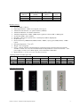
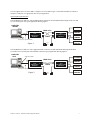
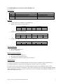
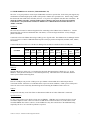
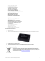
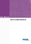
EQUIPMENT MANUAL
S.I. Tech Models 2170/2171/2172/2173 USB Fiber Products
INTRODUCTION
The S.I.Tech Models 2170 and 2171 products support USB 1.1 to fiber conversion.
The S.I.Tech Models 2172 and 2173 products support USB 2.0 to fiber conversion.
PRODUCT SPECIFICATIONS
Models 2170/2171
•
•
•
•
•
•
•
•
•
•
•
•
•
Operation Mode: USB 1.1
Input/Output Interface: USB 1.1 2170-Type B, 2171-Type A
Transmission Line Interface: ST optical connector (standard)
Transmission Distance: See distance chart below
Transmitter Output Power: 25µw into 62.5/125 micron fiber
System Wavelength: 850nm (1300nm option)
Data Rate: USB 1.0 (Low Speed) USB 1.1 (Full Speed)
Bit Error Rate: 10-9
Receiver Sensitivity: 2µw
Operating Temperature: 0oC to 50oC
Weight: 1.0lb (454 grams)
Power: External with power supply (S.I.Tech #2164-100 to 240VAC 50/60Hz to 12VDC, UL, CSA, CE &
TUVGS listed). 10 to 32V, 2170-2 Watts Max, 2171-2 Watts Min/14 Watts Max.
Metal Enclosure: 5.75” X 3.8” X 1.63” (14.6 X 9.6 X 4.2 cm)
©2006 S.I. Tech, Inc. USB Fiber Product Equipment Manual
1
Operating Distance for Fiber Optic Cable
Fiber Size
Attenuation
Distance
Distance
(Microns)
(dB/Km)
(Meters)
(Feet)
50
3.0
2000
6600
62.5
4.0
2000
6600
10*
1.0
5000
16000
* Single mode option-1300nm (Application limits may be exceeded)
Models 2172/2173
•
•
•
•
•
•
•
•
•
•
•
•
•
Operation Mode: USB 2.0
Input/Output Interface: USB 2.0 2172-Type B, 2173-Type A
Transmission Line Interface: SC optical connector (standard)
Transmission Distance: See distance chart below
Transmitter Output Power: MMF –17dBm (20µw) typical 62.5 micron, SMF –11dBm typical
System Wavelength: 850 or 1300nm
Data Rate: USB 1.0 (Low Speed), USB 1.1 (Full Speed), USB 2.0 (High Speed)
Bit Error Rate: 10-9
Receiver Sensitivity: MMF(850nm) MMF(1300nm) –29dBm (1.2µw) typical, SMF(1300nm) –32dBm
typical
Operating Temperature: 0oC to 70oC
Weight: 1.0 lb (454 grams)
Power: 9-28VDC 7W Max. External with power supply-4W typical (S.I.Tech #2164-100 to 240VAC
50/60Hz to 12VDC, UL, CSA, CE & TUVGS listed). For fully loaded 2173 use S.I.Tech #2164A – 17W
power supply. 9 to 28V, 2172-5 Watts Typical, 2173-5 Watts Min/17 Watts Max
Metal Enclosure: 5.75” X 3.8” X 1.63” (14.6 X 9.6 X 4.2 cm)
Operating Distance for Fiber optic Cable
Fiber Size
Attenuation (dB/Km)
Bandwidth (Mhz/Km)
Distance (Meters)
(Microns)
850nm
1300nm
850nm
1300nm
850nm
1300nm
50
3.0
1.5
600
600
1000
1000
62.5
4.0
1.5
200
600
400
1000
10*
Unspecified
0.4
Unspecified Unspecified
-5000
* Single mode option-1300nm (Application limits may be exceeded)
Distance (Feet)
850nm
1300nm
3300
3300
1300
3300
-16000
USB Input/Output Interface
2170
©2006 S.I. Tech, Inc. USB Fiber Product Equipment Manual
2171
2172
2173
2
S.I.Tech supplies part # 7170 for USB 1.1 and part # 7172 for USB 2.0 type A to B cable assemblies to connect to
computer’s USB port. Use appropriate cable for your application.
Optical Input/Output Interface
S.I.Tech Models 2170 and 2171 come standard with ST connectors for both multimode and single mode. 2170 and
2171 are used in pairs. See typical application drawing Figure 1.
COMPUTER
SERVER
SCANNER
Type
B
USB Cable
FIBER OPTIC
S.I.Tech
2170
USB to Fiber
Bit-Driver
Rx
Tx
2171
Tx USB HUB to Fiber
Bit-Driver
CABLE
PRINTER
S.I.Tech
Rx
Type
A
# 7170 Type A to Type B USB Cable
Figure 1.
2164
110 VAC
or
230 VAC
DIGITAL
CAMERA
STORAGE
DEVICES
2164
S.I.Tech Models 2172 and 2173 come equipped with SC connectors for both multimode and single mode fibers.
2172 and 2173 are used in pairs and connected as shown in typical application drawing Figure 2.
COMPUTER
HOST
USB2.0 Host Controller
Type
B
USB Cable
SCANNER
FIBER OPTIC
S.I.Tech
2172
USB to Fiber
Bit-Driver
Tx
Rx
Tx
Rx
CABLE
©2006 S.I. Tech, Inc. USB Fiber Product Equipment Manual
2173
USB HUB to Fiber
Bit-Driver
Type
A
# 7172 Type A to Type B USB Cable
Figure 2.
PRINTER
S.I.Tech
2164
110 VAC
or
230 VAC
2164
DIGITAL
CAMERA
STORAGE
DEVICES
3
S.I. TECH MODELS 2170 AND 2171 (USB 1.1 PRODUCTS)
LED Definition
LED
POWER
LINK
HOST
PORT
2170
Power ON
Optical signal from 2171 detected
2170/2171 pair enumerated with host USB
2171
Power ON
Host USB data detected
Host USB data detected at port
Installation
1.
2.
Connect fibers between Model 2170 and Model 2171
Apply power to model 2170 and model 2171
PWR
On
3.
HOST
Off
PWR
On
2171 LEDs
LINK
Off
PORT
Off
Connect 2170 to PC with USB cable
PWR
On
4.
2170 LEDs
LINK
On
2170 LEDs
LINK
On
HOST
On
PWR
On
2171 LEDs
LLINK
On
PORT
Off
Connect 2171 USB hub ports to USB devices with USB cables
PWR
On
2170 LEDs
LINK
On
HOST
On
PWR
On
2171 LEDs
LINK
On
PORT
On
USB Device Removal
1.
2.
Quit USB device application
Remove USB device
Models 2170 and 2171 Removal
1.
2.
3.
Remove all USB devices from 2171
Disconnect host USB cable from 2170
Disconnect power and remove fibers from 2170 and 2171
Operational Notes
A 2170/2171 pair cannot be cascaded with another 2170/2171 pair due to cumulative delays and possibility of
exceeding the capabilities of the protocol. Cascading may sometimes work but is not reliable.
The 2170/2171 pair can be connected in a cascaded arrangement with up to four USB hubs. The level of the
2170/2171 pair in the cascade is not important. A 2170 can be connected to a port of an upstream USB hub and hubs
can be connected to 2171 ports. 2170s can be connected to any or all of the ports on an USB hub. USB hubs can be
connected to each port on a 2171.
©2006 S.I. Tech, Inc. USB Fiber Product Equipment Manual
4
S.I. TECH MODELS 2172 AND 2173 (USB 2.0 PRODUCTS)
The 2172 / 2173 pair provides a remote 4-port USB2.0 hub carried over optical fiber. Each of the ports supports any
combination of USB2.0 (high-speed), USB1.1 (full-speed) or USB1.0 (low-speed) devices. Before using, confirm
that the host PC has USB2.0 host controller (the 2172 / 2173 pair is not compatible with other host controllers). To
check the USB host controller, open the Windows Device Manager and review the Universal Serial Bus
Controller list; verify that the list contains an “Enhanced” or “Enhanced Host Controller Interface” or
“EHCI” controller.
Installation
The 2172 and 2173 must be connected together before connecting to the USB2.0 host or USB devices. Connect
appropriate fiber (62.5 micron multimode fiber <500 meters, or 9 micron single mode fiber <2 km), and apply
power to both units.
Connect the 2172 to the USB2.0 host using a USB Type A to Type B cable. The Windows Device Manager lists the
2172 / 2173 pair as a Generic USB Hub and its Properties show per port Power Required (Available, 0mA, 100mA,
and 500mA).
Connect USB devices to the 2173. The Device Manager lists each device attached to the 2173 USB ports.
2172 LEDs
Condition
Power on
Fibers connected
2172 to USB2.0 host
Device on 2173 port
2173 port in overcurrent
PWR
(green)
OSD
(green)
Link
(green)
Host
(green)
PWR
(green)
On
On
On
On
Off
On
On
On
Off
On
On
On
Off
Off
On
On
On
On
On
On
2173 LEDs
Port
Link
Act
(green)
(green)
Off
Off
Off
Off
Blinking Off
On
On
On
On
On
On
On
On
Off
Port
OC
(yellow)
Off
Off
Off
Off
Off
On
On
On
On
On
OSD
(green)
Removal
Stop all USB devices on the 2172 / 2173 hub before physically disconnecting the USB devices; e.g., use the
Windows “Safely Remove Hardware” icon found in System Tray. Disconnect the 2172 USB cable, and then
remove power and the connecting fibers.
Overcurrent
Each 2173 USB port can provide +5VDC power up to 500mA to the attached device and each port has an
overcurrent monitor. When the 2173 USB hub detects a port overcurrent condition, +5VDC power on that port is
removed. Power can be restored by disconnecting and reconnecting the USB host cable at the 2172.
Caution
Unexpected results may occur if the fibers are disconnected while the 2172 host USB cable is connected.
Operational Notes
For best results, connect 2172 directly to host (not an USB hub). USB hubs may be connected to the 2173 and
cascaded to depths of 4 hubs. There is a limit of 14 USB devices connected to the 2173 (in this context, each
cascaded USB hub also count as a device). Some USB devices may have sensitivities to the additional timing
required by the 2172 / 2173 and fail to perform as expected.
©2006 S.I. Tech, Inc. USB Fiber Product Equipment Manual
5
LED Definitions
2172
Power ON
Optical signal detected
Logically connected to 2173
Host communication with 2173 hub detected
---
Power
OSD
LINK
HOST
OPR
FAULT
2173
Power ON
Optical signal detected
Logically connected to 2172 with host data detected
-Port operational
Port overcurrent fault
POWER
The Models 2170/2171/2172/2173 can be powered from normal 12VDC power. Use S.I.Tech Model 2164 (5W)
power module as it has 110VAC or 240VAC input and 12VDC output. For 2173-4 port Hub, depending upon
attached devices you may need high power, power supply. S.I.Tech Model 2164A can be used (17W).
Both 2164 and 2164A are suitable for use in most countries.
Power cord supplied with these devices is international color code. It may require a suitable plug assembly for your
specific country e.g. UK. [Green/yellow conductor is ground. The other two are for AC power terminals.]
DIAGNOSTICS
1.
2.
3.
4.
5.
Check step by step setup per above given installation and LED indications.
Make sure you have USB 1.1 Bit-drivers (2170 and 2171) for USB 1.1 application. USB 2.0 bit-drivers
(2172/2173) for USB 2.0 applications.
For USB 2.0, make sure you have USB 2.0 root hub support from USB 2.0 host controller. The USB 2.0
host controller will be identified in the Windows device manager as “Enhanced” or EHCI controller*.
Make sure you have multimode cable for multimode 2170, 2171, 2172 and 2173 or single mode cable for
single mode equipped bit-drivers.
Make sure you have 12VDC power and in case of 2173 if it is fully loaded, use high power (17W or
higher) power supply.
*Refer to 2172/2173 USB 2.0 host as device combinations.
2172/2173 USB 2.0 extension firmware tested HOST/OS combinations
USB Host Chipset
Computer
Operating System
Intel 82891FB
Dell Optiplex GX280
Fedora Core3 (kenel 2.6.9-1.667)
Intel 82891EB
Generic
Win XP SP2
Intel 82891EB
Dell Dimension 3000
Win 2000 SP4
Intel 82891EB
Dell Dimension 3000
Fedora Core3 (kenel 2.6.11-1.27)
Intel 82891DB
Shuttle XPC
Win 2000 SP4
SiS 7001
Generic
Win XP SP1
SiS 7001
Generic
Win 2000 SP4
NEC PD 720100
PCI exp card
Win XP SP2
Apple G5 USB 2.0 host
Apple PowerMac G5
OS X (10.3.9)
2172/2173 USB 2.0 extension firmware incomplete device test list
Not all devices were tested on every HOST/OS combination.
USB 2.0
Plextor PX712-UF external DVD writer
Epson Stylus PHOTO R300 USB 2.0 printer with card reader
Canon LiDE 80 USB 2.0 Scanner
©2006 S.I. Tech, Inc. USB Fiber Product Equipment Manual
6
IOGear 160GB USB 2.0 HDD
Creative WebCam Live! Pro
Creative WebCam Live! Motion
ADS USB 2.0 Turbo Webcam
Sony Micro Vault 128MB Flash
Lexar Pro Jumperdrive 2GB Flash
SanDisk Cruzer Mini Flash Drive 128MB
Sony Combo flash drive and Memory Stick Reader
Passmark Loop back plug
BAFO USB 2.0 Hub (NEC Chip)
Belkin Tetra Hub (Cypress Chip)
D-Link DUB7 7port Hub (Philips Chip)
USB 1.1
Digital Persona 4000 fingerprint reader
Logitech 4000 webcam
3Com Camera
MS USB Hub/Keyboard + Optical Mouse
Dell enhanced Hub/Keyboard + Optical Mouse
Lexar Jumperdrive 128MB USB 1.1 Flash
Lomega Zip drive
Zebsx Z-3080 Barcode Scanner
Wacom Intuous Tablet
Edgeport/4 Serial Converter
Griffen PowerMate USB volume knob
DISASSEMBLY PROCEDURE
1.
2.
Disconnect power
There are 6 (4x40) Phillips head screws (see drawing below). Remove screws using suitable screwdriver.
3.
4.
Carefully remove cover from the device.
To remove PCB from base, remove 4 (6 X 32) binding head screws using a screwdriver.
NOTICE: End of Life Product Disposal
In accordance with Waste Electrical & Electronic Equipment (WEEE) directive of
European Union countries, do not throw (dispose) these products into household waste
containers. Products should be taken to authorized material recyclers in your country. For
further information, contact http://www.erp-recycling.org.
©2006 S.I. Tech, Inc. USB Fiber Product Equipment Manual
7
IMPORTANT
If after performing troubleshooting, the unit is still not working, check with an S.I. Tech application engineer. For
optical unit service, call or write S.I. Tech Inc. at P.O. Box 609, Geneva, IL 60134, USA. Phone: 630-761-3640.
Web site: http://www.sitech-bitdriver.com. Email: [email protected].
WARNING
This equipment generates, uses, and can radiate radio frequency energy and if not installed and used in accordance
with the instruction manual, may cause interference to radio communications. It has been tested and found to
comply with the limits for a Class A computing device pursuant to Subpart J of part 15 of FCC rules, which are
designed to provide reasonable protection against such interference when operated in a commercial environment.
Operation of this equipment in a residential area is likely to cause interference in which case the user at user’s
expense will be required to take whatever action may be required to correct the interference.
WARRANTY
S.I. Tech, Inc. warrants that this item is free from defects in material and workmanship. Our warranty is limited to
repair or replacement, at our sole discretion, of any item that fails within one year of sale*.
This warranty does not apply if the item has undergone repair or alteration not authorized by S.I. Tech or if it has
been subjected to misuse, negligence or accident or other similar or dissimilar use.
S.I. TECH IS NOT RESPONSIBLE FOR INJURY, PROPERTY DAMAGE OR OTHER INDIRECT
CONSEQUENTIAL OR SPECIAL DAMAGES ARISING DIRECTLY OR INDIRECTLY OUT OF THE USE OF
THIS ITEM, NOTWITHSTANDING THE FACT THAT SAID INJURY, PROPERTY DAMAGE OR OTHER
CONSEQUENTIAL DAMAGES AROSE DIRECTLY OR INDIRECTLY FROM AN ACTUAL OR ALLEGED
DEFECT IN MATERIAL AND/OR WORKMANSHIP.
*For a nominal fee, an extended warranty is available upon request.
Warranty Registration Form
Company__________________________________________________________________
Address ___________________________________________________________________
City _________________________ State ___________________ Zip Code ____________
Date Purchased ________________________ Part Number __________________________
Type of Bit-Driver Purchased __________________________________________________
Serial Number ______________________________________________________________
Approximate Distance between Terminals ________________________________________
Environment _______________________________________________________________
Name of Registrant __________________________________________________________
Telephone Number __________________________________________________________
Fax Number ________________________________________________________________
E-Mail Address _____________________________________________________________
Warranty registration card must be completed and returned to:
S.I.Tech, P.O.Box 609, Geneva, IL 60134, for warranty to apply.
©2006 S.I. Tech, Inc. USB Fiber Product Equipment Manual
8