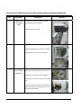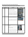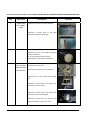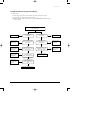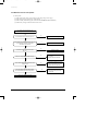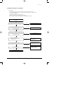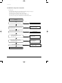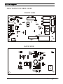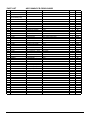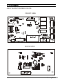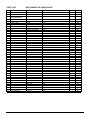
1
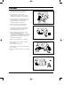
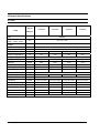
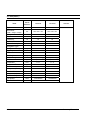
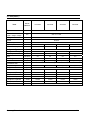
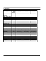
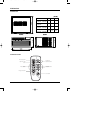
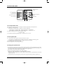
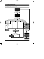
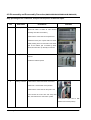
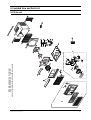
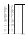
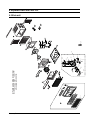
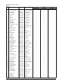
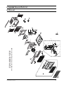
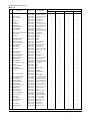
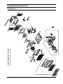
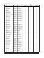
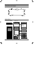
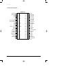
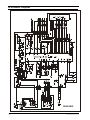
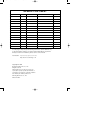
DB98_04511A(2)-CO
2/18/03 4:08 PM
Page 3
ROOM AIR CONDITIONER
AW0503B
AW0505B
AW0603B
AW0605B
AW0803B
AW0805B
AW1003B
AW1005B
AW1203B
AW1205B
AW1403B
AW1803B
SERVICE
AIR CONDITIONER
AW1805B
Manual
CONTENTS
11. Precautions
12. Product Specifications
13. Installation and Operating
Instructions
14. Disassembly and Reassembly
15. Troubleshooting
16. Exploded Views and Parts List
17. Block Diagram
18. PCB Diagram
19. Wiring Diagram
10. Schematic Diagram
SAM0001
DB98_04511A(2)-1
2/18/03 4:09 PM
Page 1-1
1. Precautions
1. Warning: Prior to repair, disconnect the
power cord from the circuit breaker.
2. Use proper parts: Use only exact
replacement parts. (Also, we recommend
replacing parts rather than repairing them.)
3. Use the proper tools: Use the proper tools
and test equipment, and know how to use
equipment may cause problems laterintermittent contact, for example.
4. Power Cord: Prior to repair, check the
power cord and replace it if necessary.
Fig. 1-1 Avoid Dangerous Contact
5. Avoid using an extension cord, and avoid
tapping into a power cord. This practice
may result in malfunction or fire.
6. After completing repairs and reassembly,
check the insulation resistance.
Procedure: Prior to applying power, measure
the resistance between the power cord and the
ground terminal. The resistance must be
greater than 30 megaohms.
7. Make sure that the grounds are adequate.
Fig. 1-2 No Tapping and No Extension Cords
8. Make sure that the installation conditions
are satisfactory.
Relocate the unit if necessary.
9. Keep children away from the unit while it is
being repaired.
10. Be sure to clean the unit and its surrounding
area.
Fig. 1-3 No Kids Nearby!
Fig. 1-4 Clean the Unit
Samsung Electronics
1-1
2.Product Specifications
2-1 Table
Item
Unit of
Measure
AW0503B
AW0505B
Type
Dimension:
AW0603B
AW0605B
WINDOW
mm
424×310×326
Voltage
Volt
115
Phase
-
SINGLE
Frequency
Hz
60
Operation Current
A
4.8
4.8
5.7
5.7
Power Consumption
W
530
530
630
630
(Width×Height×Depth)
Refrigerant Type
Refrigerant Change
FREON
R22
g
310
300
300
300
BTU/h
5200
5200
6100
6100
BTU/h.W
9.8
9.8
9.7
9.7
Net Weight
Kg
18.5
18.5
19
19
Condenser
Row
2×15
2×15
2×15
2×15
Condenser Fan
Type
Evaporator
Row
2×10
2×10
Evaporator Fan
Type
Capacity
EER
Propeller Fan
2×10
2×10
Blower
Fan Motor
MODEL
YSLA-30-6-0005
YSLA-30-6-0005
YSLA-30-6-0005
YSLA-30-6-0005
Compressor(Rotary)
MODEL
2R7S126BUC
39A050HSAKA
39A062HSAKA
39A062HSAKA
-
MRA99811-9201
KA-122-LBDN61K
KA-122-LLCN00B
KA-122-LLCN00B
Compressor Capacitor
μF/VAC
35/270
35/270
40/270
40/270
Fan Motor Capacitor
μF/VAC
3.5/270
3.5/270
3.5/27
3.5/27
RPM
1060/1010/960
1060/1010/960
1060/1010/960
1060/1010/960
Overload Protect
Fan Speed
Thermo Control
Samsung Electronics
-
THERMISTOR
2-1
2-1 Table(CONT.)
Item
Unit of
AW0803B
AW0805B
WINDOW
WINDOW
mm
500×355×461
500×355×461
Voltage
Volt
115
115
Phase
-
SINGLE
SINGLE
Frequency
Hz
60
60
Operation Current
A
7.4
7.4
Power Consumption
W
820
820
FREON
R22
R22
g
320
320
BTU/h
8000
8000
BTU/h.W
9.8
9.8
Net Weight
Kg
26.5
26.5
Condenser
Row
2×16(L-Bending)
2×16(L-Bending)
Condenser Fan
Type
Propeller Fan
Propeller Fan
Evaporator
Row
2×11
2×11
Evaporator Fan
Type
Blower
Blower
Fan Motor
MODEL
YSK40-6S-1
YSK40-6S-1
Compressor(Rotary)
MODEL
44A080HUAEB
44A080HUAEB
-
KA-122LFGN17K
KA-122LFGN17K
Compressor Capacitor
μF/VAC
45/370
45/370
Fan Motor Capacitor
μF/VAC
8/450
8/450
RPM
1030/980/920
1030/980/920
Measure
Type
Dimension:
(Width×Height×Depth)
Refrigerant Type
Refrigerant Change
Capacity
EER
Overload Protect
Fan Speed
Thermo Control
2-2
-
REMARK
THERMISTOR
Samsung Electronics
2-1 Table(CONT.)
Item
Unit of
Measure
AW1003B
AW1005B
Type
Dimension:
AW1203B
AW1205B
WINDOW
mm
560×411×548
Voltage
Volt
115
Phase
-
SINGLE
Frequency
Hz
60
Operation Current
A
9.2
9.2
11.3
11.3
Power Consumption
W
1040
1040
1240
1240
(Width×Height×Depth)
Refrigerant Type
Refrigerant Change
FREON
R22
g
390
390
560
560
BTU/h
10200
10200
12400
12400
BTU/h.W
9.8
9.8
9.8
9.8
Net Weight
Kg
37
37
38.5
38.5
Condenser
Row
2×17(L-Bending)
2×17(L-Bending)
3×17(L-Bending)
3×17(L-Bending)
Condenser Fan
Type
Evaporator
Row
Evaporator Fan
Type
Capacity
EER
Propeller Fan
2×12
2×12
2×10(φ9.52)
2×10(φ9.52)
Blower
Fan Motor
MODEL
YGN60-6B-2
YGN60-6B-2
YGN60-6B-1
YGN60-6B-1
Compressor(Rotary)
MODEL
2P16S126B1G
2P16S126B1G
2P18S126B1H
2P18S126B1H
-
MRA98695
MRA98695
MRA98896-9200
MRA98896-9200
Compressor Capacitor
μF/VAC
45/370
45/370
45/370
45/370
Fan Motor Capacitor
μF/VAC
15/250
15/250
15/250
15/250
RPM
930/890/850
930/890/850
900/850/800
900/850/800
Overload Protect
Fan Speed
Thermo Control
Samsung Electronics
-
THERMISTOR
2-3
2-1 Table(CONT.)
Item
Unit of
Measure
AW1403B
Type
Dimension:
(Width×Height×Depth)
AW1803B
AW1805B
WINDOW
mm
620×425×640
Voltage
Volt
Phase
-
SINGLE
Frequency
Hz
60
Operation Current
A
12.0
8.2/8.8
8.2/8.8
Power Consumption
W
1400
1850/1800
1850/1800
Refrigerant Type
Refrigerant Change
115
FREON
230/208
R22
g
580
700
700
BTU/h
14000
17900/17400
17900/17400
BTU/h.W
10.0
9.7/9.7
9.7/9.7
Net Weight
Kg
48.0
54.5
54.5
Condenser
Row
2×19(L-Bending)
2×19(L-Bending)
2×19(L-Bending)
Condenser Fan
Type
Evaporator
Row
Evaporator Fan
Type
Capacity
EER
Propeller Fan
2×11(φ9.52)
3×11(φ9.52)
3×11(φ9.52)
Blower
Fan Motor
MODEL
YGN59-6B
YSK160-6A-3
YSK160-6A-3
Compressor(Rotary)
MODEL
44B135HX1EL
48D180IU1EQ
48D180IU1EQ
-
MRA98693-12007
MRA12046-12007
MRA12046-12007
Compressor Capacitor
μF/VAC
50/370
35/450
35/450
Fan Motor Capacitor
μF/VAC
15/450
6/450
6/450
RPM
900/850/800
1050/1000/960
1050/1000/960
Overload Protect
Fan Speed
Thermo Control
2-4
-
THERMISTOR
Samsung Electronics
DB98-04512A(2)_1
2/19/03 10:44 AM
Page 2-3
2-2 Dimensions
2-2-1 Main Unit
(Unit : mm)
Depth
Model Name
AW0503B
AW0505B
AW0603B
AW0605B
AW0803B
Height
Depth
424
310
326
500
355
461
560
411
548
620
425
640
AW0805B
AW1003B
AW1005B
AW1203B
AW1205B
AW1403B
AW1803B
Front view
Width
AW1805B
Height
Height
Side view
Width
2-2-2 Remote Control
Timer setting button
Sleep timer setting
button
Mode selection
buttons
Temperature
adjustment buttons
Fan speed
adjustment buttons
Energy Saver button
On/Off button
Samsung Electronics
2-5
DB98_04511A(2)-1
2/18/03 4:09 PM
Page 3-1
3. Installation and Operating Instructions
3-1 Installation
3-1-1 Selecting Area for Installation
1. Make sure that you install the unit in an area
providing good ventilation. The air conditioner
must not be blocked by any obstacle affecting the
air flow near the air inlet and air outlet.
2.
Make sure that you install the unit in an area that
allow good air handling. The installation area
must be able to endure vibration from the unit.
3.
Make sure that you install the unit away from
heat or vapor.
4.
Make sure that you install the unit in an area
which is cool and has adequate space.
5.
Make sure that you install the unit in an area
away from TVs, audio units, cordless phones,
fluorescent lighting fixtures and other electrical
appliances (obtain a clearance of at least one
meter).
6.
Make sure that you install the unit in an area
which provides easy drainage for condensed
water.
7.
Make sure that you install the unit in an area not
exposed to rain or direct sunlight.
(Install a separate sunblind if exposed to direct
sunlight.)
8.
Make sure that you install the unit in an area
allowing good air movement. Do not install it in
a space that would cause noise amplification of
noise.
9. Fix the unit firmly if mounted in a high place.
Caution:
Do not use the air conditioner in the following environments : greasy areas (including areas near
machines), or marine areas. Contact your local dealer for advice.
Samsung Electronics
3-1
DB98_04511A(2)-1
2/18/03 4:09 PM
Page 3-2
3-2 Function Description
Temperature/Timer
settings
Mode
Mode selection button
(Cool,Fan, Dry)
Energy Saver button
Cool/Dry/Fan
Temp.
E.Saver
Sleep timer setting button
Sleep
Timer setting button
Timer
Power
On/Off button
Fan Speed
Fan speed adjustment button
Temperature adjustment
buttons
Remote control
3-2-1 Cooling operation mode
The compressor is turned on and off according to the ambient temperature and set temperature.
1) Compressor on and off control
• Compressor on and off control according to the ambient temperature
* The compressor is turned off when "ambient temperature = set temperature
* The compressor is turned on when "ambient temperature = set temperature +1˚C"
2) Default value after power reset ➔ set temperature = 24˚C
Fan speed = High
3) Set temperature indicating (setting) range : 1˚C interval from 18˚C to 30˚C.
3-2-2 Fan operation mode
1) If "Fan operation mode" signal is received from remocon or panel.
➔ the compressor is immediately turned off and only fan motor is operated at set blowing speed.
➔ it changes such as "High ➔ Med ➔ Low ➔ High"( if Fan speed is selected).
2) The initial Fan motor speed is set to "High".
3) The set temperature can not be indicated and set.
3-2-3 Energy saver operation mode
* If the compressor turn off at the cooling operation, the fan motor turn off after operation during the fixation
time only, and operation that energy saver by turn off the fixation time only, and operation that energy saver
by turn off the motor continuously before the condition of the compressor on.
* The fan motor is not operated at flow wind operation.
* Energy saver operation specification at the cooling operation.
1) Fan motor control in compressor on : operate with setting wind speed
2) Fan motor control in compressor off : After compressor off, the fan motor is operated breeze for 2 minutes
and then it turn off.
3) After the fan motor off, the compressor and fan motor is operated normally when the compressor on.
3-2
Samsung Electronics
DB98_04511A(2)-1
2/18/03 4:09 PM
Page 1
Installation and Operating Instructions
3-2-4 Sleep operation mode
1) Enable to sleep operation only when cooling operation.
2) First, 7-SEG LED DISPLAY "SLEEP" while 15 second, Second, 7-SEG LED DISPLAY "8Hr"
And, automatically SET OFF after operated while 8 Hour
3) If sleep operation, setting Temperature rise 1˚C after 1 Hour
4) ON TIMER operation, not operation, ENERGY SAVER operation, not sleep operation.
3-2-5 Dry operation mode
Same as Cool operation mode.
3-2-6 LED display indication in case of error detection
ERROR OPERATION
7-SEG
LED DISPLAY
ROOM THERMISTOR
(OPEN or SHORT)
E1 displayed
1) Set operation in case of error occurrence.
• Malfunction of each temperature sensor (open, short)
- Error mode display, warning sound.
- The operation status is off.
Samsung Electronics
3-3
DB98_04511A(2)-1
2/18/03 4:09 PM
Page 2
MEMO
3-4
Samsung Electronics
DB98_04511A(2)-1
2/18/03 4:09 PM
Page 3
4. Disassembly and Reassembly
4-1 Compressor Replacement Flow Chart
Locate cause of defect
Release refrigerant
Disconnect electrical wiring
from compressor
Cut refrigerant lines
from compressor
Plug disconnected lines
Replace compressor
Inspect electrical
wiring for defects,
and terminals for
correct and secure
connections
Solder discharge line
Solder suction line
Use nitrogen gas
Perform soldering function
Y
Problem?
Fill system with
nitrogen gas
N
Check for leakage
Corrective action
Leakage?
Y
Check refrigerant oil level
N
Release nitrogen gas?
Y
Low oil level?
N
Evacuate system
Add oil as necessary
Recharge system
Pinch and braze filling tube
Samsung Electronics
4-1
DB98_04511A(2)-1
2/18/03 4:09 PM
Page 4
4-2 Checking the oil
Fill the transparent container with 10cc of oil, and then conduct the test.
4-2-1 Oil quality
Oil Condition
Condition of
Refrigerant Cycle
Color
Odor
Normal
Straw Yellow
No Odor
Return with the system
Over-heated
Brown Color
-
Change the oil
Compressor Damage
Dark Brown
Pungent oil
Change the oil
Remarks
4-2-2 Replacing and refilling the refrigerant oil
1. Change the compressor - DO NOT recharge the oil as the compressor itself is
already charged.
2. Change the condenser .... add 50cc
3. Change the evaporator .... add 50cc
4. When the refrigerant is replaced .... add 30cc oil.
5. After vacuum is completed, the oil is filled through the high pressure side.
6. In the event of a refrigerant leak, generally it is not necessary to add oil.
(Unless the oil has leaked significantly.)
4-2
Samsung Electronics
4-3.Disassembly and Reassembly Procedure(AW0503B/AW0505B/AW0603B/AW0605B)
Stop operating the air conditioner, and pull out the power cord before repair.
No.
Part Name
Procedures
1
Ass’y Grille
1.Pull the Grille air inlet and Guard air filter out.
Remarks
(Pull both sides of Grille air inlet forward
carefully, then take out the filter.)
2.Remove the screw fixed on the panel front.
3.Hold the lower part of panel with two hands
while pressing down on both sides of the lower
part of the cabinet, pull it forward by about
30mm,and then lift it up carefully for removal.
2
Ass’y Cabinet
1.Remove all screws on the both side of the
cabinet .
2.Take the cabinet upward.
3
Ass’y Control
1.Remove the earth screw fixed on the base.
2.Remove 3 screws fixed on the partition.
3.Remove the screw fixed for the power cord.
4.Un-connect the motor wire and comp lead
wire, then take out the control box upward.
(The picture maybe have a little
different from actual product)
Samsung Electronics
4-3
Disassembly and Reassembly Procedure(AW0503B/AW0505B/AW0603B/AW0605B)
No.
Part Name
4
CASE EVAP
UP & ASSY
EVAP
Procedures
Remarks
1.Take the case evap up forward carefully.
(tear all the seal on it before )
2.Pull the frame up upward.
5
Blower
1.Remove all screws on the evaporator.
2.Pull the evaporator from frame low carefully.
3.Remove the nut and remove the Blower.
6
Case Cond &
Fan Propeller
& Motor Fan
1.Remove 2 screws on the rear side of the
base pan, and all screws fixed on case cond.
2.Pull up the condenser from the base pan.
3.Remove the nut and remove the Propeller
fan.
4.Remove the screw fixed on the partition and
earth screw fixed on the base pan, then take
out the motor backward.
4-4
Samsung Electronics
Disassembly and Reassembly Procedure(AW0803B/AW0805B)
Stop operating the air conditioner, and pull out the power cord before repair.
No.
Part Name
Procedures
1
Ass’y Grille
1.Pull the Grille air inlet and Guard air filter out.
Remarks
(Pull both sides of Grille air inlet forward
carefully, then take out the filter.)
2.Remove the screw fixed on the panel front.
3.Hold the lower part of panel with two hands
while pressing down on both sides of the lower
part of the cabinet, pull it forward by about
30mm,and then lift it up carefully for removal.
2
Ass’y Cabinet
1. Remove the screws on both sides of the
cabinet to disconnect the cabinet and frame.
2. Pull the handle on the front side of the
bottom, and remove the unit from the cabinet.
3
Ass’y Control
1.Remove the earth screw fixed on the plate
evaporator
2.Remove 3 screws fixed on the partition and
plate evaporator casing.
3.Remove the screw fixed for the power cord.
Samsung Electronics
4.Un-connect the motor wire and comp lead
(The picture maybe have a little
wire, then take out the control box upward.
different from actual product)
4-5
Disassembly and Reassembly Procedure(AW0803B/AW0805B)
No.
Part Name
4
CASE EVAP
UP & ASSY
EVAP
Procedures
Remarks
1.Take the case evap up forward carefully.
2.Remove 4 screws fixed on the plate
evaporator casing and evaporator.
5
Blower
1.Lift up the evaporator carefully.
2.Remove 2 screws on the plate evaporator
casing and partition.
3. Lift up the plate evaporator casing.
4.Remove the nut and remove the Blower.
6
Case Cond &
Fan Propeller
& Motor Fan
1.Remove 2 screws on the base pan, and all
screws fixed on case cond.
2.Pull up the condenser from the base pan.
3.Remove the nut and remove the Propeller
fan.
4.Remove the screw fixed on the partition and
earth screw fixed on the base pan, then take
out the motor backward.
4-6
Samsung Electronics
Disassembly and Reassembly Procedure(AW1003B/AW1005B/AW1203B/AW1205B/AW1403B/AW1803B/AW1805B)
Stop operating the air conditioner, and pull out the power cord before repair.
No.
Part Name
Procedures
1
Ass’y Grille
1.Pull the Grille air inlet and Guard air filter out.
Remarks
(Pull both sides of Grille air inlet forward
carefully, then take out the filter.)
2.Remove the screw fixed on the panel front.
3.Hold the lower part of panel with two hands
while pressing down on both sides of the lower
part of the cabinet, pull it forward by about
30mm,and then lift it up carefully for removal.
2
Ass’y Cabinet
1. Remove the screws on both sides of the
cabinet to disconnect the cabinet and frame.
2. Pull the handle on the front side of the
bottom, and remove the unit from the cabinet.
3
Ass’y Control
1.Remove the earth screw fixed on the plate
evaporator
2.Remove all screws fixed on the partition and
plate evaporator casing.
3.Remove the screw fixed for the power cord.
Samsung Electronics
4.Un-connect the motor wire and comp lead
(The picture maybe have a little
wire, then take out the control box upward.
different from actual product)
4-7
Disassembly and Reassembly Procedure(AW1003B/AW1005B/AW1203B/AW1205B/AW1403B/AW1803B/AW1805B)
No.
Part Name
4
CASE EVAP
UP & ASSY
EVAP
Procedures
Remarks
1.Take the case evap up forward carefully.
2.Remove 4 screws fixed on the plate
evaporator casing and evaporator.
5
Blower
1.Lift up the evaporator carefully.
2.Remove 2 screws on the plate evaporator
casing and partition.
3. Lift up the plate evaporator casing.
4.Remove the nut and remove the Blower.
6
Case Cond &
Fan Propeller
& Motor Fan&
Mount motor
1.Remove 2 screws on the base pan, and all
screws fixed on case cond.
2.Pull up the condenser from the base pan.
3.Remove the nut and remove the Propeller
fan.
4.Remove 4 screws fixed on the plate reinf,
then take out the case cond.
5.Remove 4 screws fixed on the mount motor
then take out the motor backward.
6.Remove 4 screws fixed on the base and
partition then remove the mount motor.
4-8
Samsung Electronics
DB98_04511A(2)-2
2/18/03 4:12 PM
Page 5-1
5. Troubleshooting
Check the basic checkpoints first to determine whether it is machine trouble or a problem
in the operation method. When it is not related to the basic checkpoints, perform checking
in accordance with the procedures of troubleshooting by symptom.
5-1 Basic Checkpoints for Troubleshooting
1) Is the voltage of the power source appropriate ?
(1) It should be within the rating voltage ±10% range.
(2) The air conditioner may not operate properly when the voltage is out of this range.
2) Is the connection with the fan motor, compressor wire, and starting condenser
appropriately made ?
3) The symptoms listed in the table below are not indicative of machine trouble.
Symptom
Cause and check
No operation
• Check whether there is power failure or the power plug is pulled out.
• Check whether the unit is stopped as a result of completion
of the sleep time.
• Pull out the power plug for ten seconds, and then insert it again.
Air flows, but
no cooling
• Check whether the Air filter is clogged with dust or is dirty.
• Check whether the desired temperature is too high. Set the desired
temperature to a lower level than the current temperature.
• Check whether it is in "FAN" mode.
The remocon does
not operate
• Check whether battery is completely depleted.
• Check whether the battery is properly inserted.
• Check whether the receiving window of the remocon for the assembly
main PCB is blinded.
• Check whether the remocon is affected by jamming due to a neon sign.
No temperature
setting
• Check whether the unit is in "FAN" mode.
(In "FAN" mode, only the current temperature is displayed, and the
desired temperature is not set.)
❈ Checking and Display of Fault Area
ERROR OPERATION
ERROR OPERATION
ROOM THERMISTOR (OPEN OR SHORT)
E1 displayed
Samsung Electronics
5-1
DB98_04511A(2)-2
2/18/03 4:12 PM
Page 5-2
5-2 Troubleshooting by Symptom
5-2-1 No power
1) Check points
(1) Is the voltage of the power source normal ? (the rating voltage ±10% range.)
(2) Is the electric wire in good contact ?(CN 71, RY 71)
(3) Is the output voltage of the IC01(KA 7812) normal ?(DC 11.5V ~ DC 12.5V)
(4) Is the output voltage of the IC02(KA 7805) normal ?(DC 4.5V ~ DC 5.5V)
Turn off the power, and then turn it on again five
seconds later.
Y
Dose the buzzer sound, when the power on?
Normal operation.
N
Check whether the "COOLING ICON" LED lamp is
on, and the operation starts when pressing the
ON/OFF button of the remocon.
Y
Normal operation.
N
Y
Is the F701(3.15A) fuse blown?
Replace the fuse.
N
Is the primary voltage of the transformer normal?
(the rating voltage ±10% range.)
N
Check the power cord and electric wire.
Y
Is the secondary voltage of the transformer normal?
(AC 13V ~ AC 17V)
N
Check and replace the trans.
Y
N
Is the rectifier diode(D101~D104) normal?
Y
- Is the voltage of DC 17V ~ DC 23V applied at both
ends of the C101 electrolytic condenser?
- Is the voltage of DC 12V applied at both ends of
the C102 electrolytic condenser?
- Is the voltage of DC 5V applied at both ends of
the C103 electrolytic condenser?
N
• Check the D101 ~ D104 for cold
soldering.
• Replace the rectifier diode
• Check both ends of the C101 for
short and cold soldering.
• Check the +12V for a short.
• Check the +5V for a short.
• Check and replace the C101~104.
Y
N
Are the IC01(KA7812) and IC02(KA7805) normal?
Y
• Check the IC01, and IC02 for cold
soldering and a short.
• Replace the IC01, and IC02.
Replace the assembly main PCB.
5-2
Samsung Electronics
DB98_04511A(2)-2
2/18/03 4:12 PM
Page 5-3
Troubleshooting
5-2-2 When the Membrane Key pad and Led Display
1) Check points
(1) Is the voltage of the power source normal ? (the rating voltage ±10% range.)
(2) Is the electric wire in good contact ?(CN71, RY71)
(3) Is the connection of the assembly main PCB, and MEMBRANE KEY PAD in good
contact? (CN91)
Turn off the power, and then turn it on again
five seconds later.
N
Normal operation
When the LED display is
not operated.
Y
Check the micom
(IC04) for a short,
and replace it.
N
Is the voltage of the micom
(IC04) No.1, 2, 38~43 port a
square wave?
Y
Check the micom
(IC04) for a short,
and replace it.
N
Is the voltage of the micom
(IC04) No.3, 4, 10, 11, 44 port
a square wave?
Y
Check the Q901~
Q905 for a short,
and replace it.
N
Is the voltage of the
Q901 ~ Q905 square wave?
When the membrane key is
not operated.
N
Normal operation
Y
Is the voltage of the
micom (IC04) No.13, 14 port
a square wave?
N
Check the micom
(IC04) for a short,
and replace it.
N
Check the micom
(IC04) for a short,
and replace it.
Y
Is the voltage of the micom
(IC04) No.3, 4, 10, 11, 44
port a square wave?
Y
Replace the membrane
key pad.
Y
Check the IC07
for a short, and
replace it.
N
Is the voltage of the
IC07 No. 10~16 a square
value?
Y
Replace the membrane key pad
Samsung Electronics
5-3
DB98_04511A(2)-2
2/18/03 4:12 PM
Page 5-4
Troubleshooting
5-2-3 When the remocon is not operated
1) Check points
(1) Is the voltage of the power source normal ? (the rating voltage ±10% range. )
(2) Is the electric wire in good contact ? (CN71, RY71)
(3) Is the assembly main PCB in good contact with the MEMBRANE KEY PAD(CN91)
(4) Is the battery voltage of the remocon above DC 2.7V?
Turn off the power, and then turn it on
again five seconds later.
N
Go to the clause "No power".
Dose the Buzzer sound, when the power on?
Y
Check whether the "COOLING ICON" LED lamp is on
and th operation starts when pressing the
on/off button of the remocon.
Y
The remocon is normally operated.
N
Is the battery voltage of the remocon above
DC 2.7V?
N
Replace the battery.
Y
N
• Check the X-TAL for cold soldering
and a short.
• Replace relevant components.
N
• Check the micom(ICT1) QT1, and
QT2 for cold soldering and a short.
• Replace relevant components.
Does the X-TAL(RJ 455JB) oscillate normally?
Y
Is the collector voltage of the remocon QT1, QT2
a square wave?
Y
Is the input voltage of the micom(IC04) No.15
pin of the assembly main PCB a aquare wave?
N
• Check the R415 components.
• Check the assembly main PCB
micom(IC04).
Y
Replace the assembly main PCB.
5-4
Samsung Electronics
DB98_04511A(2)-2
2/18/03 4:12 PM
Page 5-5
Troubleshooting
5-2-4 When the compressor is not operated
1) Check points
(1) Is the voltage of the power source normal ? (the rating voltage ±10% range. )
(2) Is the desired temperature lower than the indoor temperature in the “COOL” mode?
(Compressor stopped)
(3) Is the starting condenser in good contact?
(4) Is the electric wire in good contact ? (CN71, RY71)
(5) Is the output voltage of the IC01(KA7812) and IC02(KA7805) normal ?
Turn off the power, and then turn it on again five
seconds later.
N
Go to the clause "No power".
Dose the Buzzer sound, when the power on?
Y
Check whether the "COOLING ICON" LED lamp is on
and the operation starts when pressing the on/off
button of the remocon.
N
• Go to the clause "when he remocon
does not operate".
Y
Check whether the compressor is activated in three
minutes after turning on the power with the "CoolING
ICON" LED lamp being switched on when selecting the
cool mode of the remocon.
Y
Normal operation.
N
Is the IC03 output normal?
- When the compressor is on, IC03
No. 15 pin → Low.
N
• Check the IC03 for short and cold
soldering.
• Replace the IC03.
N
• Check the relay coil resistance.
(resistance : About 150Ω±20Ω)
• Replace the relay.
Y
Does the relay(RY71) operate normally?
- When the compressor is ON, the RY71 should operate.
Y
N
Is the compressor normal?
Y
• Check the operation of the O.L.P,
and replace it if necessary.
• Check the compressor
resistance.(0Ω : short, ∞Ω : open)
Replace the compressor.
Samsung Electronics
5-5
DB98_04511A(2)-2
2/18/03 4:12 PM
Page 5-6
Troubleshooting
5-2-5 When the air swing motor is not operated
1) Check points
(1) Is the voltage of the power source normal ? (the rating voltage ±10% range. )
(2) Is the electric wire in good contact ?(CN71, RY71)
(3) Is the swing motor connector in good contact?(CN71)
(4) Is the terminal connected to the swing motor in good contact?
(5) Is the output voltage of the IC01(KA7812) and IC02(KA7805) normal?
Turn off the power, and then turn it on again five
seconds later.
N
Go to the clause "No power".
Dose the buzzer sound, when the power on?
Y
Check whether the “COOLING ICON” LED lamp is on,
and the operation starts when pressing the ON/OFF
button of the remocon?
N
Go to the clause of “when the
remocon dose not operated”
Y
Does the air-swing motor operate when
pressing the air-swing button of the remote control?
Y
Normal operation.
N
Is the IC03 output normal?
- When the air-swing motor is on, IC03
No. 11 pin → Low
N
• Check the IC03 for a short and cold
soldering.
• Replace the IC03.
N
• Check the relay coil resistance.
(Normal: About 400Ω)
• Replace the relay.
Y
Does the relay(RY 75) operate normally?
- When the air-swing motor is operated, the
RY75 should be operated.
Y
N
Is the air-swing motor normal?
• Check the air-swing motor resistance.
(0Ω : short, ∞Ω : open)
Y
Replace the air-swing motor.
5-6
Samsung Electronics
DB98_04511A(2)-2
2/18/03 4:12 PM
Page 5-7
Troubleshooting
5-2-6 When the fan motor does not operated
1) Check points
(1) Is the voltage of the power source normal ? (the rating voltage ±10% range. )
(2) Is the electric wire in good contact ?(CN71, RY71)
(3) Is the starting condenser(FAN MOTOR) in good contact?
(4) Is the fan motor connector in good contact?(CN73)
(5) Is the output voltage of the IC01(KA7812) and IC02(KA7805) normal ?
Turn off the power, and then turn it on again five
seconds later.
N
Go to the clause "No power".
Dose the buzzer sound, when the power on?
Y
Check whether the "COOLING ICON" LED lamp is on
and the operation starts when pressing the
on/off button of the remocon.
N
• Go to the clause of "when the
remocon does not operated".
Y
Is the IC03 output normal?
- When the fan motor is High, IC03 No. 13 pin → Low.
- When the fan motor is Med, IC03 NO. 14 pin → LOW.
- When the fan motor is Low, IC03 No. 16 pin →Low.
N
• Check the IC03 for a short and cold
soldering.
• Replace the IC03.
N
• Check the relay coil resistance.
(Normal: About 400Ω)
• Replace the relay.
Y
Does the relay(RY 72, 73) operate normally?
- When the fan motor is High, RY72 should operate.
- When the fan motor is Med, RY73 should operate.
- When the fan motor is Low, RY76 should operate.
Y
Is the fan motor normal?
Y
N
• Check the fan motor resistance.
(0Ω : short, ∞Ω : open)
• Check the fan motor thermal fuse?
(130˚C)
Replace the fan motor.
Samsung Electronics
5-7
DB98_04511A(2)-2
2/18/03 4:12 PM
Page 5-8
MEMO
5-8
Samsung Electronics
Samsung Electronics
1
1-2
1-1
1-6
1-3
1-5
1-4
5
4
8
30
29-8
29-5
6
29-7
29-6
9
AW0503B/AW0505B/AW0603B/AW0605B
EXPLODED VIEW
7
10
6-1
29-9
29-3
11
29-2
29-1
29-4
29-10
12
29
14
21
28
25
13
31
15
16
27
26
22
24
23
33
17
18
20
32
19
6. Exploded View and Parts List
6-1 Main unit
Exploded View and Parts List
■Part List
No
1
Description
DB92-00516A
DB92-00516B
1-1 PANEL FRONT
DB64-00902A
1-2 GRILLE AIR INLET
DB64-00903A
DB64-01078A
1-3 BLADE V-S
DB66-00663A
1-4 BLADE V-L
DB66-00546A
1-5 LINK BLADE
DB66-00368A
1-6 GUARD AIR FILTER
DB63-00806A
2
CASE CONTROL UP
DB61-00933A
4
EVAPORATOR
DB96-01972A
5
ASSY-PLATE EVAP CASING DB90-00898A
6
NUT-FRANGE
DB60-30004A
7
BLOWER
DB67-00099A
8
ASSY-EVAP CASE UP
DB90-00944A
9
ASSY PARTITION
DB94-00438A
10 INSULATION-TUBE
DB72-50178A
11 MOTOR
DB31-00035K
12 FAN-PROPELLER
DB67-00014A
13 NUT-FRANGE
DB60-30020A
14 CASE COND
DB61-00932A
15 ASSY-COND
DB96-02044A
16 ASSY SHUTTER-LF
DB92-00336A
17 ASSY CABINET
DB90-01289A
18 SHUTTER-ANGLE UP
DB64-00518A
19 ASSY SHUTTER-RH
DB92-00337A
20 TUBE DISCHARGE
DB62-01349A
DB62-02408A
21 TUBE SUCTION
DB62-01314A
DB62-01314B
22 COMPRESSOR
39A050HSAKA
39A062HSAKA
DB95-00490A
23 NUT-TERMINAL COVER
DB60-30001A
24 GASKET
DB63-00765A
25 COVER-TERMINAL
DB63-00762A
26 NUT WASHER
DB60-30028A
27 GROMMET-ISOLATOR
DB63-00764A
28 O.L.P
DB35-00022B
DB35-00022C
DB35-00031C
29 ASSY CONTROL BOX
DB93-02550A
DB93-02550C
DB93-02550F
DB93-02550G
29-1 CASE CONTROL LOW
DB61-00934A
29-2 CASE CONTROL UP
DB61-00933A
29-3 C-OIL(COMP&FAN)
2501-001296
2501-001290
29-4 POWER CORD
DB39-00958A
29-5 TRANSFORMER
DB26-00006G
29-6 ASSY MAIN PCB
DB93-02480B
29-7 PANEL CONTROL
DB64-00904A
29-8 SWITCH MEMBRANE
DB34-00030A
DB34-00030D
29-9 CLIP CAPACITOR
DB65-00031A
29-10 THERMISTOR
DB32-10051D
30 TUBE CAPILLARY
DB62-02282A
DB62-02153A
31 ASSY BASE
DB90-00897A
DB90-00897C
32 ASSY-SCREW
DB97-90014K
33 ASSY REMOCON
DB93-01433S
6-2
ASSY PANEL FRONT
Code No.
Q'TY
Specification
SEA
SEA WALMART
SEA-2004
SEA
SEA WALMART
HIPS,T2.0,-,HIPS,T2.0,-,PP,L82,T1.3,-,
HIPS,T2.5,-,
Y-PJT,SGCC-M,T0.7
FP1.3,T3,2*10,W
Y-PJT,ASSY
2C M6 SM20C NTR
ABS,-,OK_TOP-P/J
Y-PJT,ASSY
Y-PJT,ASSY
T30,W36,L34,NBR
YGN50-6K,Y-TOP(5K)
ABS,290,6 BLADE
M6,LEFT
PP,T2,W378,L308
2R×15S,FP1.5
PVC,SC-94445R
Y-PJT,TOP
SECC-P,T1,W8
PVC,SC-94445R
C1220T-0
C1220T-0
C1220T-0
C1220T-0
115V 60Hz 1Ph
115V 60Hz 1Ph
2R7S126A6F
M5,-,SM20C
EPDM,T0.8
GE,-,NORYL,-,SEI-701
M8,ZPC
EPDM,-,BLK,OK-PJT
39A062HSAKA
39A050HSAKA
MAE COMP
5K ELEC
6K ELEC
SEA-WALMART,5K
SEA-WALMART,6K
Y-PJT,SGCC-M,T0.7,
Y-PJT,SGCC-M,T0.7,W
3.5/40UF
3.5/35UF
Y-TOP,ELEC.,UL,P
AC115V,50/60HZ
Y-P/J,SSEC
ABS,T2.0,
PE,-,-,40~350
PE,-,-,40~350
SGCC-M,T0.45
10K/25,-,3425K
1.2×1100mm
1.2×900mm
MSWR10,M8,L10
MSWR10,M8,L10
OK-P/J
OK-PJT,ARC-735
AW0503B
AW0505B
AW0603B
AW0605B
1
1
1
2
2
2
1
1
1
1
1
1
1
1
1
1
1
1
1
1
1
1
1
1
1
1
1
1
1
1
3
3
1
1
1
1
1
1
1
1
1
1
1
1
1
1
1
1
1
1
1
2
2
2
1
1
1
1
1
1
1
1
1
1
1
1
1
1
1
1
1
1
1
1
1
1
1
1
3
3
1
1
1
1
1
1
1
1
1
1
1
1
1
1
1
1
1
1
1
2
2
2
1
1
1
1
1
1
1
1
1
1
1
1
1
1
1
1
1
1
1
1
1
1
1
1
3
3
1
1
1
1
1
1
1
1
1
1
1
1
1
1
1
1
1
1
1
2
2
2
1
1
1
1
1
1
1
1
1
1
1
1
1
1
1
1
1
1
1
1
1
1
1
1
3
3
1
1
1
1
1
1
1
1
1
1
1
1
1
1
1
1
Samsung Electronics
Samsung Electronics
1
1-2
1-1
1-7
1-6
1-3
2
1-5
1-4
5
4
8
AW0803B/AW0805B
6
34-12
34-9
30
EXPLODED VIEW
34-11
9
34-10
7
10
6-3
34-8
34-7
34-3
34-5
34-1
34-4
34-2
11
34-6
12
34
14
21
28
25
13
31
15
16
29
27
26
22
24
23
20
17
18
33
32
19
6. Exploded View and Parts List
6-3 Main unit
Exploded View and Parts List
■Part List
No
1
Description
Code No.
Q/TY
Specification
ASSY PANEL FRONT
DB92-00515B
ASSY,SEA
AW0803B
AW0805B
1
-
ASSY PANEL FRONT
DB92-00515C
ASSY,SEA,WALMART
-
1
1-1
PANEL FRONT
DB64-00916A
H1-P/J,HIPS,T2.0
1
1
1-2
GRILLE AIR INLET
DB64-00917A
H1-P/J,HIPS,T2.0
1
1
GRILLE AIR INLET
DB64-01089A
H1-P/J,HIPS,T2.0
-
1
1-3
BLADE V-S
DB66-00556A
H1-P/J,PP,T2.0
1
1
1-4
BLADE V-L
DB66-00555A
H1-P/J,PP,T2.0
2
3
1-5
LINK BLADE
DB66-00558A
H1-PJT,PP,L106.5
2
2
1-6
GUARD AIR FILTER
DB63-00810A
H1-P/J,HIPS,T2.5
1
1
1-7
FRAME BLADE
DB61-01530A
H1-P/J,SEA,HIPS
1
1
2
LEVER DAMPER
DB66-00557A
H1-P/J,ABS
1
1
4
EVAPORATOR
DB96-02987A
R2*11*FP1.2SLIT
1
1
5
ASSY-PLATE EVAP CASING
DB90-01257A
H1-P/J,ASSY
1
1
6
NUT-FRANGE
DB60-30004A
2C M6 SM20C NTR
1
1
7
BLOWER
DB67-50078A
ABS,-,OK_TOP-P/J
1
1
8
ASSY-EVAP CASE UP
DB90-01266A
H1-PJT
1
1
9
ASSY PARTITION
DB94-00416A
H1-P/J
1
1
10
INSULATION-TUBE
DB73-00177A
NBR-FOAM
1
1
11
MOTOR
DB31-00215A
YSK40-6S-1,H1-PJT
1
1
12
FAN-PROPELLER
DB67-50077A
ABS,290
1
1
13
NUT-FRANGE
DB60-30020A
M6,-,FEFZY,LF
1
1
14
CASE COND
DB61-01532A
H1-P/J,PP,T2.0,W448
1
1
15
ASSY-COND
DB96-03161B
7.0-2*16,1.3
1
1
16
ASSY SHUTTER-LF
DB92-00113C
H1-P/J,ASSY
1
1
17
ASSY CABINET
DB90-01256A
H1-PJT
1
1
18
SHUTTER-ANGLE UP
DB64-00048H
H1-P/J,HIPS,T3.0
1
1
19
ASSY SHUTTER-RH
DB92-00112C
H1-P/J,ASSY
1
1
20
TUBE DISCHARGE
DB62-02269A
C1220T-0,T0.7,OD7
1
1
21
TUBE SUCTION
DB62-02270A
C1220T-0,T0.7,OD9.52
1
1
22
COMPRESSOR
1
1
23
NUT-TERMINAL COVER
DB60-30001A
M5,-,SM20C
1
1
24
GASKET
DB63-00765A
EPDM,0.8,-,-,-,65-70,
1
1
25
COVER-TERMINAL
DB63-00762A
GE NORYL
1
1
26
NUT WASHER
DB60-30028A
HEX 2C M8 ZPC
3
3
27
GROMMET-ISOLATOR
DB63-00763A
44A,NR35
3
3
28
O.L.P
DB35-00022A
44A080HUAEB
1
1
29
ASSY REMOCON
DB93-01433S
OK-PJT,ARC-735
1
1
34
ASSY CONTROL CASE
DB93-02487A
AW0803B
1
-
DB93-02487C
AW0805B
-
1
34-1 CASE CONTROL LOW
DB61-01535A
H1-P/J,SGCC-M,T0
1
1
34-2 CASE CONTROL UP
DB61-01536A
H1-P/J,SGCC-M,T0
1
1
34-3 BRK CONTROL
DB61-01533A
H1-P/J,SGCC-M,T1.0,
1
1
34-4 TRANSFORMER
DB26-00006J
-,AC115V,50/60HZ,DC
1
1
1
44A080HUAEB 1PH,115V/60Hz
34-5 C-OIL(FAN MOTOR)
2301-001448
8000nF,+10-5%,440V
1
34-6 POWER CORD
DB39-00343D
125V,13A,-,-
1
1
34-7 C-OIL(COMPRESSOR)
2501-001230
45uF,400V,BK
1
1
34-8 CLIP-CAPACITOR
DB65-00031A
SGCC-M,T0.45
1
1
34-9 THERMISTOR
DB32-10051E
10K/25,-,3435K,
1
1
34-10 ASS'Y MAIN PCB
DB93-02478C
H,SEA
1
1
34-11 PANEL CONTROL
DB64-00918A
H1-P/J,ABS,T2.0,W90
1
1
34-12 SWITCH MEMBRANE
DB34-00031A
PE,SEA
1
-
DB34-00031D
PE,SEA##WALL
-
1
DB62-02298A
1.42×1200mm
-
1
30
TUBE CAPILLARY
31
ASSY BASE
DB90-01255A
H1-P/J
1
1
32
ASSY-SCREW
DB97-30156C
SPS/GEA,
1
1
33
BRACKET INSTALL
DB61-30219F
GE,SPS-P/J,SGCC-A
2
2
6-4
REAMRK
Samsung Electronics
Samsung Electronics
2
1
1-1
1-7
1-2
1-3
3
1-5
1-4
5
4
8
29
30-12
30-9
6
30-11
30-10
9
AW1003B/AW1005B/AW1203B/AW1205B
EXPLODED VIEW
7
6-5
30-8
30-7
30-3
30-5
30-1
30-4
30-2
10
35
30-6
11
30
12
34
14
21
28
25
13
36
31
15
16
27
26
22
24
23
20
17
18
33
32
19
6. Exploded View and Parts List
6-5 Main unit
Exploded View and Parts List
■Part List
Q'TY
No
1
Description
ASSY PANEL FRONT
1-1
1-2
PANEL FRONT
GRILLE AIR INLET
1-3
1-4
1-5
1-7
2
3
4
BLADE V-S
BLADE V-L
LINK BLADE
FRAME BLADE
GUARD AIR FILTER
LEVER DAMPER
EVAPORATOR
5
6
7
ASSY-PLATE EVAP CASING
NUT-FRANGE
BLOWER
8
9
10
11
12
13
14
15
ASSY-EVAP CASE UP
ASSY PARTITION
INSULATION-TUBE
MOUNT MOTOR ASSY
FAN-PROPELLER
NUT-FRANGE
CASE COND
ASSY-COND
16
17
18
19
20
21
22
ASSY SHUTTER-LF
ASSY CABINET
SHUTTER-ANGLE UP
ASSY SHUTTER-RH
TUBE DISCHARGE
TUBE SUCTION
COMPRESSOR
23
24
25
26
27
28
NUT-TERMINAL COVER
GASKET
COVER-TERMINAL
NUT WASHER
GROMMET-ISOLATOR
O.L.P
30
ASSY CONTROL BOX
30-1
30-2
30-3
30-4
30-5
30-6
30-7
30-8
30-9
30-10
30-11
30-12
CASE CONTROL LOW
CASE CONTROL UP
BRK CONTROL
TRANSFORMER
C-OIL(FAN MOTOR)
POWER CORD
C-OIL(COMPRESSOR)
CLIP-CAPACITOR
THERMISTOR
ASS'Y MAIN PCB
PANEL CONTROL
SWITCH MEMBRANE
29
31
32
33
34
TUBE CAPILLARY
ASSY BASE
ASSY-SCREW
BRACKET INSTALL
MOTOR FAN
35
36
PLATE REINF
REMOCON ASSY
6-6
Code No.
Specification
DB92-00553C
DB92-00553B
DB64-00924A
DB64-00925A
DB64-01076A
DB66-00561A
DB66-00560A
DB66-00562A
DB61-01538A
DB63-00813A
DB66-00559A
DB96-02926A
DB96-02939A
DB90-01286A
DB60-30004A
DB67-50073A
DB67-50078A
DB90-01342A
DB97-02047A
DB73-00178A
DB90-01420A
DB67-00139A
DB60-30020A
DB61-01537A
DB96-02940A
DB96-02900A
DB92-00111A
DB90-01284A
DB64-00048J
DB92-00110A
DB62-02287A
DB62-02213A
DB95-00491A
DB95-00492A
DB60-30001A
DB63-00990A
DB63-00989A
DB60-30028A
DB63-00991A
DB35-00031A
DB35-00031B
DB93-02520A
DB93-02520C
DB61-00669B
DB61-00670A
DB61-00676A
DB26-00006J
2301-001452
DB39-00343E
2501-001230
DB65-00031A
DB32-10051E
DB93-02478C
DB64-00929A
DB34-00032A
DB34-00032D
DB62-02367A
DB90-01285B
DB97-30156C
DB61-30219F
DB31-00211A
DB31-00211B
DB70-00367A
DB93-01433S
ASSY,SEA
ASSY,SEA,WALMART
H2-P/J,HIPS,T2.0,W393,L
H2-P/J,HIPS,T2.5
H2-P/J,HIPS,T2.5
H2-P/J,PP,T2.0
H2-P/J,PP,T2.0,-,-,H2-PJT,TOP,PP,L106
H2-P/J,TOP,SEA,HIPS
H2-P/J,HIPS,T2.5
H2-P/J,HIPS
OD7*2R*12*FP1.5*470
OD9.52*2*10*FP1.3*4
H2-P/J,ASSY
M6 SM20C NTR
ABS,200
ABS,_180
H2-P/J,PP,T2.5
H2-PJT,FOAM-PE
H2-PJT TOP
ABS+G.F20%,D352
M6,-,FEFZY,LF
H2-P/J,PP,T2.5
3R*OD7*17*FP1.5*SLIT
2R*OD7*17*FP1.5*SL
J-P/J,ASS'Y
H2-PJT,-,HIPS,T3.0,-,-,SC
J-P/J,ASS'Y
H2-P/J,C1220T-0,TO.7
H2-P/J,C1220T-0
2P16S126B1K,10K BTU
2P18S126B1F,12K BTU
M5,-,SM20C,MAE
MAE
HEX 2C M8 ZPC
MAE
MRA98695
MRA98896-9200
SEA
SEA WALMART
H2-PJT TOP,SGCC-M,
8K TOP,SGCC-M,T0.7,
TOP,N-PROJECT,SGCC-
-,AC115V,50/60HZ,DC
15000nF,+10-5%,250V,
-,-,-,125V,13A,AWG
45uF,400V,BK,53x95mm,20.6
SGCC-M,T0.45,-,-,OK-,10K/25,-,3435K,-,-,-,H,SEA
H2-P/J,ABS,-,W79.8,
-,-,-,PE,-,-,40~350
-,-,-,PE,SEA##WALL
AW10**HAA,C1220T-O,-
H2-P/J,44 FRAME
-,-,-,-,-,-,SPS/GEA,
GE,SPS-P/J,SGCC-A
YFK-70A-6B
YGN60-6B-2
H2-P/J,SGCC-M
OK-PJT,ARC-735
AW1003B
AW1005B
AW1203B
AW1205B
1
1
1
2
2
2
1
1
1
1
1
1
1
1
1
1
1
1
1
1
1
1
1
1
1
1
1
1
1
1
1
3
1
1
1
1
1
1
1
1
1
1
1
1
1
1
1
1
1
1
2
1
1
1
1
1
1
2
2
2
1
1
1
1
1
1
1
1
1
1
1
1
1
1
1
1
1
1
1
1
1
1
1
1
1
3
1
1
1
1
1
1
1
1
1
1
1
1
1
1
1
1
1
1
2
1
1
1
1
1
1
2
2
2
1
1
1
1
1
1
1
1
1
1
1
1
1
1
1
1
1
2
2
2
1
1
1
1
1
1
1
1
1
1
1
1
1
1
1
1
1
1
1
1
1
1
1
1
1
3
1
1
1
1
1
1
1
1
1
1
1
1
1
1
1
1
1
1
2
1
1
1
1
1
1
1
1
1
1
1
1
3
1
1
1
1
1
1
1
1
1
1
1
1
1
1
1
1
1
1
2
1
1
1
Samsung Electronics
Samsung Electronics
2
1
1-1
1-7
1-2
1-3
3
1-5
1-4
5
4
8
6
30
37-9
37-3
37-4
AW1403B/AW1803B/AW1805B
EXPLODED VIEW
9
37-8
7
10
35
37-10
37-1
11
34
37-2
12
25
13
21
28
37-7
37-5
37-6
14
31
15
16
27
26
22
24
23
37
20
29
17
18
33
32
19
6. Exploded View and Parts List
6-7 Main unit
6-7
Exploded View and Parts List
■Part List
No
1
Description
ASSY PANEL FRONT
1-1
1-2
PANEL FRONT
GRILLE AIR INLET
1-3
1-4
1-5
1-7
2
3
4
BLADE V-S
BLADE V-L
LINK BLADE
FRAME BLADE
GUARD AIR FILTER
LEVER DAMPER
EVAPORATOR
5
6
7
8
9
10
ASSY-PLATE EVAP CASING
NUT-FRANGE
BLOWER
CASE EVAP UP
ASSY PARTITION
INSULATION-TUBE
11
MOUNT MOTOR
12
13
14
15
FAN-PROPELLER
NUT-FRANGE
CASE COND
ASSY-COND
16
17
18
19
20
ASSY SHUTTER-LF
ASSY CABINET
SHUTTER-ANGLE UP
ASSY SHUTTER-RH
TUBE DISCHARGE
21
TUBE SUCTION
22
COMPRESSOR
23
24
25
26
27
28
NUT-TERMINAL COVER
GASKET
COVER-TERMINAL
NUT WASHER
GROMMET-ISOLATOR
O.L.P
37
ASSY CONTROL BOX
37-1
37-2
37-3
37-4
37-5
CASE CONTROL
BRACKET-CONTROL
ASSY MAIN PCB
THERMISTOR
CAPACITOR(6mfd)
37-6 CAPACITOR(35mfd)
37-7 POWER-CORD
37-8 PANEL-CONTROL
37-9 MEMBRANE PAD
37-10 TRANSFORMER
30
TUBE CAPILLARY
31
ASSY BASE
32
33
34
ASSY-SCREW
BRACKET INSTALL
MOTOR FAN
35
29
6-8
PLATE REINF
REMOCON ASSY
Code No.
DB92-00519A
DB92-00519B
DB64-00912A
DB64-00913A
DB64-01099A
DB66-00551A
DB66-00550A
DB66-00552A
DB61-01524A
DB63-00807A
DB66-00553A
DB96-03039A
DB96-02969A
DB90-01288A
6021-001056
DB67-00096A
DB61-01528A
DB97-02027A
DB73-00173A
DB73-00173B
DB61-01496A
DB61-01512A
DB67-00047B
DB60-30028A
DB61-01495A
DB96-02699B
DB96-02699C
DB92-00109A
DB90-01217B
DB64-01020A
DB92-00108A
DB62-02469A
DB62-02593A
DB62-02470A
DB62-02234A
44B135HX1EL
48D180IU1EQ
DB60-30001A
DB63-20003A
DB63-10026A
DB60-30028A
DB73-10001A
DB47-20001U
DB35-00011C
DB93-02510A
DB93-02510B
DB93-02510C
DB61-01527A
DB61-01526A
DB93-02478C
DB32-10051E
2301-001449
2301-001452
2501-001237
2501-001231
DB39-00344B
DB39-00343F
DB64-00911A
DB34-00033A
DB34-00033D
DB26-00006K
DB26-00006J
DB96-02970A
DB96-03150A
DB90-01215B
DB90-01215C
DB97-90014U
DB61-30219F
DB31-00214C
DB31-00236A
DB70-00342A
DB93-01433S
Q'TY
Specification
SEA,ASSY
SEA,WALMART
H3-P/J,TOP,SEA,HIPS
H3-P/J,TOP,SEA
H3-P/J,TOP,SEA
H3-PJT,HIPS,T2.5,
H3-PJT,HIPS,T2.5
H3-PJT,TOP,PP,T1.3,
H3-P/J,TOP,SEA,HIPS
H3-PJT,SEA,TOP
H3-P/J,TOP,SEA,ABS
OD9.52*R3*11HOLE
OD9.52*R3*11HOLE
H3-P/J,ASSY
HEX-PLANGE,M8XP1
ABS+G/F20%,M-P/J
H3-P/J,TOP,25F0AM-PS
PP,T2.5,-,-,BLK,-,
H3-PJT,TOP,NRB
AW1403B,TOP,NRB
H3-P/J,SGCC-M
H3-P/J,SGCC-M
ABS,OD390,-,-,M-P/J
HEX 2C M8 ZPC
H3-P/J,PP,T2.5
H3-P/J,H3-P/J,AW1403B
M-P/J,ASS'Y
AW1803B/XAA,H3-PJT
-,HIPS,T3.0,W41,L6
M-P/J,ASS'Y
AW1403M/XAA,C1220T
H3-P/J,C1220T-0,TO.7
AW1403M/XAA,C1220T
H3-P/J,C1220T-0,TO.8
1PH,115V/60Hz
1PH,208-230V/60Hz
M5,-,SM20C
EPDM,T0.8
GE,-,NORYL
HEX 2C M8 ZPC
EPDM
MRA98693-12007
MRA12046-12007
AW1803B/XAA
AW1403B/XAA
AW1805B/XAA
H3-P/J,TOP,SGCC-M,T0.7
H3-P/J,TOP,SGCC-M,T
H,SEA
-,10K/25,-,3435K,-,-,-,6000nF,+10-5%,440V,B
15uF
35uF,450V
50uF
250V,13A,AWG
250V,15A,AWG
H3-P/J,TOP,SEA,ELEC
-,-,-,PE,-,-,40~350
SEA WALMART
AC230V,50/60HZ,DC
AC115V,50/60HZ,DC
ID1.3×1200×3EA
ID1.42×1400×2EA
H3-PJT
H3-PJT,FOR 44 COMP
M-P/J,(XAX)
GE,SPS-P/J,SGCC-A,T
YSK160-6A-3,18K-C TOP
YGN59-6B
H3-P/J,SGCC-M,-,T0.8
SEA
AW1403B
AW1803B
AW1805B
1
1
1
1
2
2
1
1
1
1
1
1
1
1
1
1
1
1
1
1
1
1
1
1
1
1
1
1
1
1
1
3
3
1
1
1
1
1
1
1
1
1
1
1
1
1
1
1
2
1
1
1
1
1
1
1
2
2
1
1
1
1
1
1
1
1
1
1
1
1
1
1
1
1
1
1
1
1
1
1
1
1
1
3
3
1
1
1
1
1
1
1
1
1
1
1
1
1
1
1
2
1
1
1
1
1
1
1
2
2
1
1
1
1
1
1
1
1
1
1
1
1
4
1
1
1
1
1
1
1
1
1
1
1
1
3
3
1
1
1
1
1
1
1
1
1
1
1
1
1
1
1
2
1
1
1
Samsung Electronics
DB98_04511A(2)-2
2/18/03 4:12 PM
Page 7-5
7. Block Diagram
7-1 Refrigerating Cycle Block Diagram
PINCH PIPE
(SERVICE VALVE)
SUCTION LINE
DISCHARGE LINE
ACCUMULATOR/COMPRESSOR
EVAPORATOR
CONDENSER
CAPILLARY TUBE
PINCH PIPE
(SERVICE VALVE)
7-2 Basic Structure
7-2-1 Micom Control Diagram
MAIN MICOM
Membrane Pad control
Room Temperature sensor
A/D converter
Receiving Unit of Remocon
(Key operation)
• Energe saver
• Temp.set(↑, ↓)
• Operation, Mode
• Swing, Sleep
• Fan select, Timer
(Remote Control)
Led display control
(Remocon control)
Operation
Dry
Remocon Single
Receiving
• Remocon single control
Timer
Sleep
Compressor
Fan speed (high)
• Compressor control
Fan speed (med)
• Buzzer control
Fan speed (low)
Fan
• Temperature control
Fan motor
Power circuit (DC 5V)
• Fan motor control
Powercircuit (DC 12V)
Cool
Energy saver
Reset Circuit
Down Trans (AC15V)
Oscillation Circuit
Power input (AC220V)
Temp.setting(↑)
Temp.setting(↓)
Samsung Electronics
7-1
DB98_04511A(2)-2
2/18/03 4:12 PM
Page 7-6
Block Diagram
7-2-2 Micom pin assignment
KS88C4716
SEG-DATA(c)
1
P0.1
P4.4
44
GRID5
SEG-DATA(b)
2
P0.0
P0.2
43
SEG-DATA(d)
GRID4
3
P4.3
P0.3
42
SEG-DATA(e)
GRID3
4
P4.2
P0.4
41
SEG-DATA(f)
Vcc
5
VDD
P0.5
40
SEG-DATA(g)
Vss
6
VSS
P0.6
39
SEG-DATA(h)
10MHz RESONATOR
7
Xout
P0.7
38
SEG-DATA(a)
10MHz RESONATOR
8
Xin
P1.0
37
EEPROM CLK
TEST
9
TEST
P1.1
36
EEPROM IN
GRID2
10
P4.1
P1.2
35
EEPROM OUT
GRDI1
11
P4.0
P1.3
34
BUZZER
RESET IC OUTPUT
12
RESET
P1.4
33
OPTION
KEY-IN1
13
P2.0
P1.5
32
JIG OUTPUT
KEY-IN2
14
P2.1
P3.7
31
OPTION
REMOCON
15
P2.2
P3.6
30
SENSOR THERMIS-
EEPROM CS
16
P2.3
P3.5
29
TOR(103AT)
LOW FAN
17
P2.4
P3.4
28
OPTION
COMPERSSOR
18
P2.5
P3.3
27
OPTION
MIDDLE FAN
19
P2.6
P3.2
26
OPTION
HIGH FAN
20
P2.7
P3.1
25
OPTION
4-WAY VALVE
21
P4.5
P3.0
24
SAVE OPTION
Vcc
22
AVref
AVss
23
SWING MOTOR
GND
7-2
Samsung Electronics
8. PCB Diagram
ASSY MAIN PCB:DB93-02480
FRONT SIDE
BACK SIDE
8-1
Samsung Electronics
PART LIST
ASSY MAIN PCB: DB93-02480B
NO.
DESCRIPTION
SPEC
1 IC
ULN2003AD
2 DIODE-BRIDGE(CHIP) DF06S
DIODE3
LL4148
SWITCHING(CHIP)
4 DIODE
UF4002 100V/1A
5 TRI-DIODE-CHIP
2SC2412K
6 REGULATOR
KA7805
7 REGULATOR
KA7812
8 C-AL
CD110X,10V,100uF
9 C-AL
CD110X,35V,1000uF
10 C-AL
CD110X,25V,2200uF
11 C-CHIP
101K,2012,50V
12 C-CHIP
102K,2012,50V
13 C-CHIP
104Z,2012,50V
14 C-CHIP
223Z,2012,50V
15 R-CHIP
6.8K,2012,1%,1/8W
16 R-CHIP
1K,2012,5%,1/10W
17 R-CHIP
10K,2012,5%,1/10W
18 R-CHIP
10K,2012,1%,1/10W
19 R-CHIP
330,2012,5%,1/10W
20 R-CHIP
2.2K,1/10W,5%,2012
21 R-CHIP
3.3K,1/10W,5%,2012
22 R-CHIP
4.7K,1/10W,5%,2012
23 R-CHIP
28.7K,1%,1/10W,2012
24 R-CHIP
120,5%,1/4W,1206
25 R-CARBON
620,1/2W(SMALL),5%
26 BUZZER
SP-D2220APP
27 CERAMIC RESONATOR 10MHz
28 HEAT SINK
L15 W15 H25
29 CONNECTOR
SMW250-02(RED)
30 CONNECTOR
SMW250-03(RED)
31 CONNECTOR
FCZ254-08S(BLK)
32 CONNECTOR
VH-4A( WHT)
33 CONNECTOR
VH-5A (WHT)
34 FUSE
250V,T3.15A
35 RELAY-POWER
DU1PU,16A,250V
36 RELAY-POWER
F3AA012E
37 SCREW TAPPING
PH3 L8
38 JUMP WIRE
PH0.6,L7.5mm
39 JUMP WIRE
PH0.6,L10mm
40 JUMP WIRE
PH0.6,L12.5mm
41 PCB-MAIN
5KFR-1,63*113*1.6MM
42 IC
KA75330Z
43 CHIP-MCU
KS88C4716
44 LED DISPLAY
CSE-42202G
45 REMOCON
FRP-4021H10
46 FUSE HOLDER
HF-004/J
SAMSUNG ELECTRONICS
REMARK
Q'TY
2
1
INSTALL
SMT
SMT
D901-----D905
5
SMT
D01
Q01
IC02
IC01
C103
C101
C102
C407
C408,C409,C902
C105,C106,C01,C02,C403,C404,C410
C901,C501,C502,C001
R403
,R201,R202
R03,R501,R412,R901,R301
R414
R902,R415,R406
R01
R02
OPTION2
OPTION1
R903,R904,R905,R906,R907,R908,R909
R601
BZ61
X501
1
1
1
1
1
1
1
1
3
7
4
1
2
5
1
3
1
1
1
1
7
1
1
1
1
1
1
1
1
1
1
1
3
1
12
1
1
1
1
1
1
1
2
MI
SMT
MI
MI
AI
MI
MI
SMT
SMT
SMT
SMT
SMT
SMT
SMT
SMT
SMT
SMT
SMT
SMT
SMT
SMT
AI
MI
MI
MI
MI
MI
MI
MI
MI
MI
MI
MI
MI
AI
AI
AI
IC03,IC07
BD01
CN41
CN12
CN91
CN11
CN73
F701
RY71
RY72,RY73,RY76
J1,J2,J4--J8,J11--J15
J9
J10
30522A4
IC05
IC04
LED01
RM41
F701
AI
SMT
MI
MI
MI
8-2
8. PCB Diagram
ASSY MAIN PCB:DB93-02478
FRONT SIDE
BACK SIDE
8-3
Samsung Electronics
PART LIST
ASSY MAIN PCB: DB93-02478C
NO.
DESCRIPTION
SPEC
1 IC
ULN2003AD
2 DIODE-BRIDGE(CHIP) DF06S
DIODE3
LL4148
SWITCHING(CHIP)
4 DIODE
UF4002 100V/1A
5 TRI-DIODE-CHIP
2SC2412K
6 REGULATOR
KA7805
7 REGULATOR
KA7812
8 C-AL
CD110X,10V,100uF
9 C-AL
CD110X,35V,1000uF
10 C-AL
CD110X,25V,2200uF
11 C-CHIP
101K,2012,50V
12 C-CHIP
102K,2012,50V
13 C-CHIP
104Z,2012,50V
14 C-CHIP
223Z,2012,50V
15 R-CHIP
6.8K,2012,1%,1/8W
16 R-CHIP
1K,2012,5%,1/10W
17 R-CHIP
10K,2012,5%,1/10W
18 R-CHIP
10K,2012,1%,1/10W
19 R-CHIP
330,2012,5%,1/10W
20 R-CHIP
2.2K,1/10W,5%,2012
21 R-CHIP
3.3K,1/10W,5%,2012
22 R-CHIP
4.7K,1/10W,5%,2012
23 R-CHIP
28.7K,1%,1/10W,2012
24 R-CHIP
120,5%,1/4W,1206
25 R-CARBON
620,1/2W(SMALL),5%
26 BUZZER
SP-D2220APP
27 CERAMIC RESONATOR 10MHz
28 HEAT SINK
L15 W15 H25
29 CONNECTOR
SMW250-02(RED)
30 CONNECTOR
SMW250-03(RED)
31 CONNECTOR
FCZ254-08S(BLK)
32 CONNECTOR
VH-3A(RED)
33 CONNECTOR
VH-5A (WHT)
34 FUSE
250V,T3.15A
35 RELAY-POWER
DI1U 12VDC
36 RELAY-POWER
OJ-SS-112DM(5A)
37 SCREW TAPPING
PH3 L8
38 JUMP WIRE
PH0.6,L7.5mm
39 JUMP WIRE
PH0.6,L10mm
40 PCB-MAIN
FR-1,63*113*1.6MM
41 IC
KA75330Z
42 CHIP-MCU
KS88C4716
43 LED DISPLAY
CSE-42202G
44 REMOCON
FRP-4021H10
45 FUSE HOLDER
HF-004/J
SAMSUNG ELECTRONICS
REMARK
Q'TY
2
1
INSTALL
SMT
SMT
D901-----D905
5
SMT
D01
Q01
IC02
IC01
C103
C101
C102
C407
C408,C409,C902
C105,C106,C01,C02,C403,C404,C410
C901,C501,C502,C001
R403
R201,R202
R03,R501,R412,R901,R301,
R414
R902,R415,R406
R01
R02
OPTION2
OPTION1
R903,R904,R905,R906,R907,R908,R909
R601
BZ61
X501
1
1
1
1
1
1
1
1
3
7
4
1
2
5
1
3
1
1
1
1
7
1
1
1
1
1
1
1
1
1
1
1
3
1
12
1
1
1
1
1
1
2
MI
SMT
MI
MI
AI
MI
MI
SMT
SMT
SMT
SMT
SMT
SMT
SMT
SMT
SMT
SMT
SMT
SMT
SMT
SMT
AI
MI
MI
MI
MI
MI
MI
MI
MI
MI
MI
MI
MI
AI
AI
MI
AI
SMT
MI
MI
MI
IC03,IC07
BD01
CN41
CN12
CN91
CN11
CN73
F701
RY71
RY72,RY73,RY76
J1,J2,J4--J9,J11--J14
J10
30522B4
IC05
IC04
LED01
RM41
F701
8-4
DB98_04512A(2)_2
2/19/03 10:46 AM
Page 7-2
9. Wiring Diagram
GRN
GND
GND
COMPRESSOR
CAPACITOR
FAN
MOTOR
DIAGRAM
9-1
AW0503B/AW0505B
AW0603B/AW0605B
Samsung Electronics
DB98_04512A(2)_2
2/19/03 10:46 AM
Page 7-2
9. Wiring Diagram
DIAGRAM
Samsung Electronics
AW0803B
AW0805B
9-2
DB98_04512A(2)_2
2/19/03 10:46 AM
Page 7-2
9. Wiring Diagram
DIAGRAM
9-3
AW1003B/AW1203B/AW1403B
AW1005B/AW1205B/AW1803B/AW1805B
Samsung Electronics
10. Schematic Diagrams
DB93-02480
10-1
Samsung Electronics
10. Schematic Diagrams
DB93-02478
10-2
Samsung Electronics
DB98_04511A(2)-2
2/18/03 4:12 PM
Page 10-6
UPDATE LOG SHEET
Application date
Page
Part#
Note(Cause & Solution)
Use this page to keep any special servicing information. (Service Bulletin, etc.)
If only parts number changes, Just change parts number directly on parts list.
And if you need more information, please see the service website.
Itself Solution
Integrated technology supporting electronic library
http://itself.sec.samsung.co.kr
Copyright © 2003
By Samsung Electronics Co., Ltd.
All rights reserved.
This manual may not, in whole or in part, be
copied, photocopied, reproduced, translated, or
converted to any electronic or machine readable
from without prior written permission of
Samsung Electronics Co., Ltd.
Printed in China.
S/Bulletin#
DB98_04511A(2)-CO
2/18/03 4:08 PM
Page 2
ELECTRONICS
© Samsung Electronics Co., Ltd. Dec. 2003.
Printed in China
Code No. DB81-00025A