1
DECcolorwriter 120ic Printer
User Guide
0ic
r 12
write
DEC
Order Number: EK-LJ12E-UG-001
DECcolorwriter 120ic Printer
User Guide
Order Number: EK-LJ12E-UG-001
Digital Equipment Corporation
Maynard, Massachusetts
First Printing, August 1994
Digital Equipment Corporation makes no representations that the use of its products in the manner described in this publication
will not infringe on existing or future patent rights, nor do the descriptions contained in this publication imply the granting of
licenses to make, use, or sell equipment or software in accordance with the description.
Possession, use, or copying of the software described in this publication is authorized only pursuant to a valid written license from
Digital or an authorized sublicensor.
© Digital Equipment Corporation 1994. All rights reserved.
The following are trademarks of Digital Equipment Corporation:
DEC, DECcolorwriter 120ic, DECwriter 110i, and the DIGITAL logo.
OSF/1 is a registered trademark of Open Software Foundation, Inc.
All other trademarks and registered trademarks are the property of their respective holders.
The Energy Star TM emblem does not represent EPA endorsement of any product or service.
International Standards Conformity
This equipment conforms to the specifications of the EEC Directive 87/308 on the prevention and elimination of radio-frequency
disturbances.
Si dichiara che questa apparecchiatura è conforme alle disposizioni della direttiva CEE/87/308 per la prevenzione ed
eliminazione dei radiodisturbi (D.M. 13 aprile 1989).
Ce matériel est conforme aux normes CEE/87/308 sur la prévention et l'élimination des perturbations radio-électriques.
Dieses Gerät entspricht den EWG 87/308 und VDE 0871 Bestimmungen für Verhütung und Beseitigung von Funkstörungen.
Este aparato responde a las especificaciones de la norma CEE/87/308 sobre la prevención y eliminación de radiointerferencias.
La localización e indentificación de los elementos antiparasitarios se halla descrita en el manual de asistencia técnica del
producto.
NOTE: This equipment has been tested and found to comply with the limits for a CLASS B digital device pursuant to Part 15 of
the FCC Rules. These limits are designed to provide reasonable protection against harmful interference in a residential
installation. This equipment generates, uses and can radiate radio frequency energy and, if not installed and used in accordance
with the instructions, may cause harmful interference to radio communications. However, there is no guarantee that interference
will not occur in a particular installation.
If this equipment does cause harmful interference to radio or television reception, which can be determined by turning the
equipment off and on, the user is encouraged to try to correct the interference by one or more of the following measures:
•
•
•
•
Reorient or relocate the receiving antenna.
Increase the separation between the equipment and receiver.
Connect the equipment into an outlet of a circuit different from that to which the receiver is connected.
Consult the dealer or an experienced radio/TV technician for assistance.
Changes or modifications not expressly approved by the party responsible for compliance could void the user's authority to
operate the equipment.
Connection of peripherals requires the use of grounded shielded signal cables.
This digital equipment does not exceed the CLASS B limits for radio noise emissions from digital apparatus set out in the
interference-causing equipment standard entitled "Digital Apparatus", ICES-003 of the Industry Canada.
Ce dispositif numérique respecte les limites bruits radioélectriques applicables aux appareils numériques de CLASSE B prescrites
dans la norme sur le matériel brouilleur : "Appareils Numériques", NMB-003 édictée par le ministère des Communications.
Normenkonformität und Zulassungen
Dieses Gerät entspricht den BMPT-Verfügungen 243/1991 und 46/1992 sowie DIN VDE 0878 Teil 3/11.89, zur Vermeidung
von Funkstörungen. Zusatz für periphere Geräte (z.B. Monitore, Drucker)
Dieses Gerät trägt als Hinweis, daß es den Funk-Entstöranforderungen der BMPT- Verfügung Nr. 243/1991 entspricht, das
VDE-Funkschutzzeichen. Der Zusatz "Vfg. 243/P" soll in Kurzform ausdrücken, daß es sich um ein peripheres (nicht selbständig
betreibbares) Gerät handelt, das nur einzeln den Funk- Entstöranforderungen der Grenzwertklasse B nach DIN VDE 0878 Teil
3/11.89 und der BMPT-Verfügung 243/1991 entspricht.
Wird das Gerät innerhalb einer Anlage zusammen mit anderen Geräten betrieben, muß bei Inanspruchnahme der "Allgemeinen
(Betriebs-) Genehmigung" nach der BMPT-Verfügung 243/1991 die gesamte Anlage der Grenzwertklasse
B nach DIN VDE 0878 Teil 3/11.89 sowie den Voraussetzungen nach 2 und den Auflagen nach 3 der BMPT-Verfügung
243/1991 entsprechen.
Dies ist in der Regel nur dann erfüllt, wenn das Gerät in einer Anlage betrieben wird, die typgeprüft und mit dem VDEFunkschutzzeichen mit dem Zusatz "Vfg. 243" gekennzeichnet ist.
Für Geräte welche der DPR-Verfügung 1046/1984 entsprechen und dem VDE- Funkschutzzeichen mit dem Zusatz "0871-B/P"
gekennzeichnet sind, gilt obiges sinngemäß.
GS
Dieses Gerät ist nach dem Gerätesichereitsgesetz GSG i.d.F. vom GS 13.8.1979 3 Abs. 4 geprüft.
Netzleitung
Netzleitung muß geprüftem Typ H05VV entsprechen.
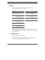
Schallemissionswerte
Werteangaben nach ISO 9296 und ISO 7779 / DIN EN27779 :
Schalleistungspegel
LwAd,B
Scalldruckpegel
LpAm, dBA
(Zuchauerpositionen)
Leerlauf
Betrieb
Leerlauf
Betrieb
Draft
--
6,3
--
47
Briefqualität
--
6,1
--
46
[Aktuelle Werte für spezielle Ausrüstungsstufen sind über die Digital Equipment Vertretungen erhältlich. 1 B = 10 dBA.]
Limited Warranty
Digital Equipment Corporation warrants to the purchaser that this product is free from defects in
workmanship and materials and will perform substantially in accordance with the documentation
accompanying the product for a period of two years from the date of purchase of this product. Digital's
warranty does not apply to conditions resulting from improper use, external causes, or modifications to this
product. Digital does not warrant that the operation or execution of the product shall be uninterrupted or
error-free. This limited Warranty does not apply to any third party software products which come with their
own software product warranty, if any.
Some jurisdictions do not allow limitations on how long an implied warranty lasts, so the above limitation
may not apply to you. Digital will either repair, refurbish, or replace the product through a standard, Returnto Digital Warranty. The purchaser pays for one-way transportation and insurance to the return center
authorized by Digital's Technical Support and Service Hotline. For customers outside the United States of
America, a different local warranty may apply. To obtain details, contact your local Digital sales office or
place of purchase.
For warranty services under your Return-to-Digital Warranty within the continental United States of America,
please call our toll-free Technical Support and Service Hotline at: 1-800-354-9000, push 42 for warranty
operator. In Canada call 1-800-267-5251 (English), or 1-800-267-2603 (French). For customers in other parts
of the world, please call your local sales office for support and service. Retain your dated sales receipt as your
proof of purchase and warranty. You will also be asked to furnish Model and Serial Numbers.
Disclaimer of Warranties and Allocation of Liability
THE ABOVE WARRANTIES ARE PURCHASER'S EXCLUSIVE WARRANTIES AND NO OTHER
WARRANTY EXPRESS OR IMPLIED, SHALL APPLY. DIGITAL SPECIFICALLY DISCLAIMS THE
IMPLIED WARRANTIES OF MERCHANTABILITY AND FITNESS FOR A PARTICULAR PURPOSE.
DIGITAL'S LIABILITY TO PURCHASER FOR ANY CAUSE WHATSOEVER SHALL BE LIMITED TO
THE ACTUAL PURCHASE PRICE PAID TO DIGITAL OR ITS AUTHORIZED RESELLER FOR THE
PRODUCT THAT ARE THE SUBJECT OF PURCHASER'S CLAIM. IN NO EVENT WILL DIGITAL BE
LIABLE FOR ANY DAMAGES RESULTING FROM LOSS OF DATA OR USE, LOST PROFITS, OR ANY
INCIDENTAL OR CONSEQUENTIAL DAMAGES.
Some jurisdictions do not allow the exclusion or limitation of liability for consequential or incidental
damages, so the above limitation may not apply to you. This warranty gives you specific legal rights, and you
may also have other rights which depend on local law.
Table of Contents
Preface..................................................................................vii
Features ............................................................................................ viii
The Documentation Set........................................................................ ix
The Setting Up Your Printer Booklet................................................................... ix
The User Guide................................................................................................... ix
The Structure of the Manual ..................................................................................x
Conventions ....................................................................................... xii
1. Introducing DECcolorwriter 120ic Printer ..................... 1-1
Unpacking the Printer ........................................................................ 1-1
Carton Contents ................................................................................ 1-2
Printer Location................................................................................. 1-3
Printer Parts ...................................................................................... 1-4
Monochrome Print Head.................................................................... 1-6
Color Print Head ............................................................................... 1-7
Print Head Selection Lever ................................................................ 1-8
Paper Loading Levers........................................................................ 1-9
Selector Switches ............................................................................ 1-10
Operator Panel ................................................................................ 1-11
Indicators .........................................................................................................1-11
Buttons ............................................................................................................1-13
i
Table of Contents
2. Getting Started ............................................................... 2-1
Inserting the Paper Input Tray ........................................................... 2-1
Mounting the Paper Output Tray ....................................................... 2-3
Loading Paper into the Printer ........................................................... 2-4
Connecting to the Computer............................................................... 2-9
Connecting the Parallel Interface Cable ............................................................. 2-9
Connecting to the Power Outlet........................................................ 2-10
Switching On the Printer.................................................................. 2-11
Installing the Print Head .................................................................. 2-12
Running the Printer Self Test........................................................... 2-15
Printer Self Test Contents.................................................................................2-16
Installing the Windows Printer Drivers............................................. 2-23
Running the Windows Print Test...................................................... 2-27
3. Operating the Printer ..................................................... 3-1
Media Printing Side ........................................................................... 3-1
Automatic Insertion Printing Side ...................................................................... 3-1
Manual Insertion Printing Side .......................................................................... 3-2
Media Characteristics ........................................................................ 3-2
Paper Types ...................................................................................................... 3-2
Transparencies .................................................................................................. 3-3
Dimensions ....................................................................................................... 3-4
Print Area ......................................................................................... 3-5
Inserting a Document Manually ......................................................... 3-7
Printing with Windows Applications .................................................. 3-8
Selecting the Proper Windows Printer Driver..................................................... 3-8
Printer Drivers Setup......................................................................................... 3-9
Monochrome Printing with the DECcolorwriter 120ic Driver ........... 3-19
Assistance ....................................................................................... 3-20
ii
Table of Contents
4. Maintenance .................................................................. 4-1
Basic Maintenance Operations........................................................... 4-1
Changing the Print Head.................................................................... 4-2
Cleaning the Print Head ..................................................................... 4-6
Replacing the Monochrome Ink Cartridge .......................................... 4-7
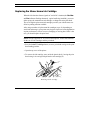
Priming the Monochrome Print Head ................................................. 4-9
Transporting the Printer................................................................... 4-11
Storing the Print Heads.................................................................... 4-12
5. Troubleshooting.............................................................. 5-1
Contacting your Digital Services Center............................................. 5-1
Returning the Printer for Maintenance............................................................... 5-2
Digital Customers Services Centers ................................................................... 5-2
Windows Warnings ........................................................................... 5-3
Indicators Warnings .......................................................................... 5-4
Solving Problems............................................................................... 5-5
Contents............................................................................................................ 5-5
Installation Problems......................................................................................... 5-6
Paper Problems ................................................................................................. 5-8
Printing Problems.............................................................................................5-11
iii
Table of Contents
A. Accessories and Options............................................. A-1
Accessories ...................................................................................... A-1
Monochrome Print Head and Ink Cartridge........................................................A-1
Color Print Head ...............................................................................................A-2
Transparencies ..................................................................................................A-2
Options ............................................................................................ A-2
PCMCIA Emulation Card..................................................................................A-2
PCMCIA Font Cards .........................................................................................A-2
PCMCIA RAM Card .........................................................................................A-3
Serial Interface ..................................................................................................A-3
Parallel Data Cables..........................................................................................A-3
Optional Card Insertion .................................................................... A-4
Using the Serial Interface within Windows ........................................ A-5
B. Fonts ................................................................................B-1
Introduction...................................................................................... B-1
Resident Fonts.................................................................................. B-2
Font Handling Using Command Codes.............................................. B-5
Down-Line Loading of Fonts .............................................................................B-5
iv
Table of Contents
C. Printer Controlling ......................................................... C-1
The Communication Protocol............................................................ C-1
Printing Methods within DOS Environment....................................... C-3
Printing a Text Screen.......................................................................................C-3
Printing Text Files ............................................................................................C-3
Software Applications ...................................................................... C-5
Printer Drivers ..................................................................................................C-5
Incorporated Commands ................................................................... C-8
Sending Files to the Printer ............................................................... C-9
Printer Programming within DOS Environment ............................... C-10
Factory Settings...............................................................................................C-10
Selector Switches Set-Up Procedure................................................ C-12
Access to the Selector Switches .......................................................................C-12
How to Select the Feature Settings ..................................................................C-13
Termination of Set-Up Procedure ....................................................................C-13
Programmable Features ...................................................................................C-14
Resident Emulation (HP DeskJet 500).............................................................C-14
Hexadecimal Print-Out ................................................................... C-21
Running a Hexadecimal Print-Out ...................................................................C-21
D. Emulation and Character Sets..................................... D-1
The Concept of Emulation ................................................................ D-1
Character Sets .................................................................................. D-2
Resident Character Sets Tables......................................................... D-6
v
Table of Contents
E. Command Codes .......................................................... E-1
Introduction.......................................................................................E-1
Use of Control Codes.........................................................................E-2
Command Codes Reference Tables ....................................................E-3
Basic Operations ............................................................................................... E-3
Fonts and Character Sets ................................................................................... E-4
Color Printing ................................................................................................... E-4
Down-Line Loading........................................................................................... E-4
Print Attributes ................................................................................................. E-5
Page Size .......................................................................................................... E-6
Vertical Positioning of Cursor ........................................................................... E-7
Horizontal Positioning of Cursor........................................................................ E-8
Graphic Printing................................................................................................ E-9
Others ............................................................................................................. E-10
F. Technical Characteristics .............................................. F-1
Printer Interface.................................................................................F-5
Parallel Interface Characteristics........................................................F-5
Slow Down Mode.............................................................................................. F-9
Serial Interface Characteristics (Option) .......................................... F-10
Logical Connection.......................................................................................... F-12
Data Exchange Procedures .............................................................................. F-13
vi
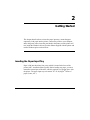
Preface
This chapter introduces the features of the DECcolorwriter 120ic printer and
explains the purpose and the structure of the documentation set.
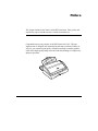
Congratulations on your purchase of the DECcolorwriter 120ic. This nonimpact printer is designed and constructed to guarantee excellent reliability. It
will give you consistent print quality of both text and high resolution graphics.
It also offers high speed printing associated with the advantage of compact size
and quiet operation.
ter 1
20ic
rwri
colo
DEC
vii
Preface
Features
A number of benefits are provided by the DECcolorwriter 120ic, including the
following:
High quality color printing
Your printer allows you excellent color printing, using "drop on demand"
thermal ink jet technology. It produces a laser-like print density of up to 300 x
300 dots per inch (dpi). For monochrome printing, note that the black ink is
water-resistant.
Multimedia printing
The standard paper handling devices allow the use of a wide range of media
types and sizes: paper or transparencies single sheets (Letter, A4, Legal...),
envelopes (COM-10, DL...). The Printer Drivers are specially designed to
optimize printing using these different media.
Low cost ownership
The monochrome print head has a rechargeable system which allows you to
only change the ink cartridge, instead of changing the whole print head.
Furthermore, the DECcolorwriter 120ic Printer Driver includes an Economy
mode designed to save ink.
The DECcolorwriter 120ic has a very low power consumption (25 W - less
than a standard light bulb). This consumption is conformable to EPA
(Environment Protection Agency) norms.
Ease of use
The user-friendly driver interface and the simple operator panel make this
printer very easy to use. A Setting Up Your Printer booklet is also provided to
help you quickly install your DECcolorwriter 120ic.
viii
Preface
Compatibility
This printer can be connected to personal computers with a standard parallel or
optional serial interface. Compatible with MS-Windows and many other
software applications commonly used with this class of printer, it can be used
in most working environments. The resident firmware emulates the HP DeskJet
500C printer (extended PCL-III commands).
Numerous options
Additional emulations (EPSON LQ 850, IBM Proprinter X24, including
character sets), RAM and fonts, which increase and extend the printer's
operating range, are available as options.
The serial interface kit represents another useful option.
Configured in the appropriate operating environment, this compact size printer
is the ideal output tool for Word Processing and Desktop Publishing
applications.
The Documentation Set
The Setting Up Your Printer Booklet
This is a quick guide that contains everything you need to know to install your
printer for the first time. It may also be useful to read the Preface and Chapter
1 of the User Guide to get to know your printer thoroughly before you start.
The User Guide
This manual contains all the information required to install, configure and
operate the printer. It is intended for use by both first-time and experienced
users.
ix
Preface
The Structure of the Manual
The manual is structured for consecutive and reference reading. We
recommend you read and follow all the instructions carefully. Always refer to
the manual whenever you encounter a problem. The objectives of the chapters
are as follows:
Chapter 1 - Introducing DECcolorwriter 120ic
This chapter helps you check you have received everything you need, locate the
most suitable environment for the printer, and identify the various parts and
controls on the printer.
Chapter 2 - Getting Started
This chapter shows you how to insert the paper input tray, mount the paper
output tray, load paper, connect the printer to your computer and to the power
outlet, install the ink jet print head, run the printer self test, install the Windows
Printer Drivers, and run the Windows print tests.
Chapter 3 - Operating the Printer
This chapter discusses the types of media you can use with your
DECcolorwriter 120ic printer. It also describes how to print within the
Windows 3.1x environment.
Chapter 4 - Maintenance
This chapter helps you perform day-to-day maintenance during the printer's
working life.
Chapter 5 - Troubleshooting
This chapter contains a troubleshooting guide, for problems which may occur,
and how to solve them. It also contains information on how to contact Digital
Services Centers when you require support.
x
Preface
A series of appendices describe the accessories and options available, the
resident and optional fonts, DOS printer controlling, the characters tables, the
command codes for the resident emulation and the technical characteristics.
The manual also contains a glossary of terms and an alphabetical index.
NOTE: In the sections regarding the logical connection to the computer, and
the installation and use of software, this manual can provide only a general
outline with some basic hints. For more detailed information, you must consult
the documentation of your operating system and application packages.
xi
Preface
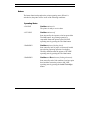
Conventions
The text contains three different types of annotation which should always be
read.
NOTE: This NOTE gives you, or indicates where you can find, additional
information.
CAUTION: This CAUTION should catch your attention, advising you of a
particular situation / problem which may occur / be avoided as a result of a
certain sequence of operations.
It may also contain a reminder to execute a particular operation.
WARNING: This WARNING indicates a specific procedure which must be
strictly observed.
Failure to comply with the instructions given may result in injury to the
operator and / or damage to the printer.
xii
1
Introducing DECcolorwriter 120ic Printer
This chapter helps you check you have received everything you need, choose
the most suitable environment for the printer, and identify the various parts and
controls.
Unpacking the Printer
• Lay down the carton flat, with the opening to one side.
• Take the storage box, the plastic box and the printer out of the carton.
Remove all packing and securing tapes from the printer and its accessories.
You may also remove the label on the top cover.
CAUTION: Keep the carton and all the packing materials in case you have
transport the printer any distance, relocate it, or return it to Digital Services
for maintenance.
As soon as you have unpacked the printer and its accessories, check that all the
parts have been delivered and are undamaged.
1-1
Introducing DECcolorwriter 120ic Printer
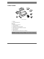
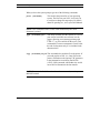
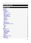
Carton Contents
6
7
8
5
4
9
1
2
3
Carton contents
1. Printer
2. Print head storage box
Plastic box
3. Monochrome print head
4. Color print head
5. Setting Up Your Printer booklet
6. DECcolorwriter 120ic Printer User Guide
7. Paper output tray
8. Paper input tray
9. DECcolorwriter 120ic Printer Drivers diskette
CAUTION: If anything is missing or damaged, call your dealer immediately.
1-2
Introducing DECcolorwriter 120ic Printer
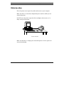
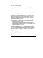
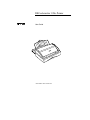
Printer Location
Place the printer on an ample, flat, stable surface near to your computer.
Make sure there is a convenient, independent power outlet to which you can
connect the printer.
Do NOT leave the printer exposed to direct sunlight or heat sources, or in
dusty or dirty environments.
Printer location
Make sure that there is enough space around the printer for all its parts to be
accessed comfortably.
1-3
Introducing DECcolorwriter 120ic Printer
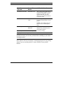
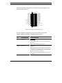
Printer Parts
3
2
4
1
5
6
7
10
11
12
9
13
8
18
17
19
16
20
15
21
14
22
Front / rear / inside views
1-4
Introducing DECcolorwriter 120ic Printer
The figures on the previous page show a front, rear and internal front view of
the printer. The following parts are indicated :
1. Paper input tray
2. Paper output tray
3. Slot for optional emulation / font card (covered)
4. Top cover
5. Operator panel
6. Paper insertion guide (for manual paper feed)
7. Paper loading (securing and centering) levers
8. Electrical data plate (on underside of printer)
9. Parallel interface cable socket
10. Mounting slots for paper output tray
11. Main ON/OFF switch
12. Power cable
13. Paper input tray insertion area
14. Ink slide
15. Selector switches
16. Print head carriage
17. Ink jet print head
18. Instruction template on inside top cover
19. Selector switches cover (open)
20. Carriage motor
21. Print head selection lever
22. Ink tube
1-5
Introducing DECcolorwriter 120ic Printer
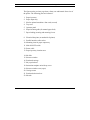
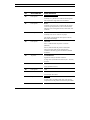
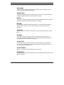
Monochrome Print Head
The monochrome (black ink) print head consists of an outer casing (1), with
the nozzles and electrical contacts, and a replaceable ink cartridge (2) which
fits inside the outer casing and is held in place by the ring (3).
1
2
3
Monochrome print head
NOTE: For information on how to insert / remove the print head in / from the
printer, see the sections entitled "Installing the Print Head" in Chapter 2 of this
manual and "Changing the Print Head" in Chapter 4 of this manual.
NOTE: For information on how to replace the ink cartridge, see the section
entitled "Replacing the Monochrome Ink Cartridge" in Chapter 4 of this
manual.
1-6
Introducing DECcolorwriter 120ic Printer
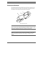
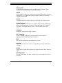
Color Print Head
The color print head is larger than the monochrome print head and includes an
ink cartridge with three ink reservoirs for colored inks. Unlike the monochrome
print head, the color print head and ink cartridge are a single unit and cannot be
replaced separately.
Color print head
NOTE: For information on how to insert / remove the print head in / from the
printer, see the sections entitled "Installing the Print Head" in Chapter 2 of this
manual and "Changing the Print Head" in Chapter 4 of this manual.
1-7
Introducing DECcolorwriter 120ic Printer
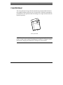
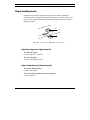
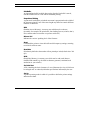
Print Head Selection Lever
The print head selection lever is located on the manual paper insertion guide,
under the top cover.
COLOR
BLACK
Print head selection lever
This lever must be positioned on the BLACK position, towards the front of the
printer (according to the indications engraved near the lever) when a
monochrome (black ink) print head is used.
If the color print head is inserted, this lever must be positioned on the COLOR
position, towards the inside of the printer (according to the indications
engraved near the lever).
NOTE: For information on the positioning of the print head selection lever, see
the sections "Installing the Print Head" in Chapter 2.
1-8
Introducing DECcolorwriter 120ic Printer
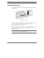
Paper Loading Levers
On the lower front of the printer there are two levers which control the
centering and the securing of the paper in the paper tray. On the inside of the
top cover, the template illustrates the functions of these levers for the paper
loading operation.
A
B
A: Paper securing lever - B: Paper centering lever
Paper Securing Lever (Upper Lever A)
To release the paper:
• Lower and move to the left.
To secure the paper:
• Move to the right and raise.
Paper Centering Lever (Lower Lever B)
To open the lateral guides:
• Move to the right.
To close the lateral guides and centre the paper:
• Move to the left.
1-9
Introducing DECcolorwriter 120ic Printer
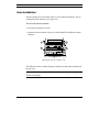
Selector Switches
Selector switches are used on this printer to select functional features, such as
resident font used, character style, paper size...
To access the selector switches:
• Lift up the top printer cover (1).
• Open the selector switches cover (2). A label identifies the different selector
switches.
1
1
2
2
Opening the selector switches cover
The different selector switches settings are displayed on the label located inside
the top cover.
NOTE: For more information about selector switches settings, see Appendix C
"Printer Controlling".
1-10
Introducing DECcolorwriter 120ic Printer
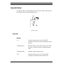
Operator Panel
The operator panel, on the right hand side of the printer, has three buttons and
two indicators (LED: Light-Emitting Diodes).
On-Line
Install Cartridge
Form Feed
On
Operator panel
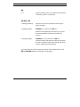
Indicators
On Line
- Lit
Indicates that the printer is in the ON LINE
operating state (under operator and computer system
control).
- Flashing slowly
Indicates that there is no paper in the printer or that
the paper is loaded incorrectly (warning operating
state).
- Flashing rapidly
Indicates a failure operating state.
- Off
Indicates that the printer is in the OFF LINE
operating state (under operator control only).
1-11
Introducing DECcolorwriter 120ic Printer
On
- Lit
Indicates that the printer is switched on, and remains
lit until the printer is switched off.
On-Line + On
- Flashing alternately
Indicates an end of ink condition or that no print
head is installed.
- Flashing sequence
On-Line twice followed by On once
Indicates incompatibility between the type of print
head inserted and the print head selection lever
position.
- Flashing sequence
On-Line five times followed by On once
Indicates that the print head inserted does not match
the data received from the printer (the Printer Driver
requires a different print head type).
At printer switch-on, after the correct execution of the mechanical reset, the
On and On-Line indicators will both be lit and steady.
1-12
Introducing DECcolorwriter 120ic Printer
Buttons
The button functions depend on the printer operating states. When it is
switched on, the printer will be in one of the following conditions:
Operating States
- ON LINE
On-Line indicator lit
The printer is ready to receive data.
- OFF LINE
On-Line indicator off
State imposed by the operator, who has pressed the
On-Line button. Any printing operation is
suspended. Return the printer to the ON LINE
operating state by pressing the On-Line button.
- WARNING
On-Line indicator flashing slowly
State caused by lack of paper or incorrectly loaded
paper during a printing operation. Load paper
carefully and then return the printer to ON LINE
operating state by pressing the On-Line button.
- WARNING
On-Line and On indicators flashing alternately
State caused by end of ink condition. Load new print
head, and then return the printer to ON LINE
operating state by pressing the Install Cartridge
button.
1-13
Introducing DECcolorwriter 120ic Printer
- WARNING
On-Line and On indicators flashing with the
sequence On-Line twice followed by On once
State caused by incompatibility between the type of
print head inserted and the position of the print head
selection lever. Load the correct type of print head
and / or position the print head selection lever
correctly, and then return the printer to the ON LINE
operating state by pressing the Install Cartridge
button.
- WARNING
On-Line and On indicators flashing with the
sequence On-Line five times followed by On once
State caused by incompatibility between the type of
print head inserted and the Printer Driver loaded.
Insert correct type of print head, and then return the
printer to the ON LINE operating state using the
Install Cartridge button.
1-14
Introducing DECcolorwriter 120ic Printer
Functional States
One of the following states will be present in the ON LINE or OFF LINE
operating states.
- FREE
No data to be printed.
- BUSY
From the reception of data until the completion of its
printing.
- IDLE
Data to be printed, but awaiting a Form Feed
command (from console or line).
Buttons Functions
- On-Line
Toggles the printer ON LINE / OFF LINE operating
states. Affects the On-Line indicator status.
- Install Cartridge
Positions the print head carriage for a print head
replacement operation. Replacement request
signalled by status of On and On-Line indicators.
Replacement anomalies signalled by status of same
indicators.
- Form Feed
Printer ON LINE and FREE
Commands the manual insertion of a single sheet of
paper to the Top of Form (TOF) position, even if
insertion from the paper tray is selected (selector
switch C OFF). If paper is already present in the
printer, causes its expulsion.
1-15
Introducing DECcolorwriter 120ic Printer
- Form Feed
Printer ON LINE and BUSY, paper already inserted
Executes the "FLUSH" function which consists of
the immediate printing of any pending data, and the
expulsion of the printed page.
- Form Feed
Printer OFF LINE and paper already inserted
Expels the paper present in the printer.
- Form Feed
Printer OFF LINE and no paper in the printer
Commands the manual insertion of a single sheet of
paper to the Top of Form (TOF) position, even if
insertion from the paper tray is selected (selector C
OFF).
Functions Activated with Button Combinations
Function
Button(s)
Operation
Print test
Install
Cartridge +
mains switch
Before activating this function, check that
there is paper loaded in the paper tray.
On-Line +
Install
Cartridge
+ mains switch
Before activating this function, check that
there is paper loaded in the paper tray.
Hexadecimal
printing
1-16
Pressing and holding down this button while
switching on the printer starts the print test
(see Chapter 2).
Pressing and holding down these buttons
while switching on the printer causes all
subsequent data transmitted to the printer to
be printed in hexadecimal format (see
Appendix C)
2
Getting Started
This chapter describes how to insert the paper input tray, mount the paper
output tray, load paper into the printer, connect the printer to your computer
and to the power outlet, insert the print head in the printer, run the printer self
test, install the Windows drivers from the diskette supplied with the printer and
run the Windows print test from Write.
Inserting the Paper Input Tray
Paper is fed into the printer from a tray which is located in the base of the
printer (ASF - Automatic Sheet Feeder). Before loading any paper, you must
mount the external part of the ASF, which is supplied as a separate piece with
the printer. The paper input tray can contain 70 x 21 lb (80g/m2) sheets of
paper (Letter, A4...).
2-1
Getting Started
Paper input tray
• Align the mounting feet of the paper input tray with the support slots on the
printer and push the paper tray into the base of the printer (1).
•
Fit the power cable in the notch on the right side of the tray (2).
2
1
Inserting the paper input tray
CAUTION: Push the external part of the paper tray in as far as it will go,
against the printer casing.
2-2
Getting Started
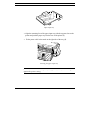
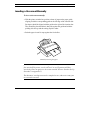
Mounting the Paper Output Tray
Printed pages are expelled from the printer into an output tray which is fitted to
the upper rear of the printer. This clear plastic tray is supplied as a separate
piece with the printer. The paper output tray can contain up to 30 x 21 lb (80
g/m2) sheets. Its central part must be extended in order to support the printed
pages correctly.
Paper output tray
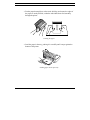
• Insert the paper output tray feet into the corresponding slots in the rear
casing of the printer.
Mounting the paper output tray
2-3
Getting Started
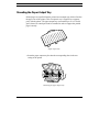
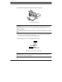
• Pull out the extendible support of the paper output tray to ensure the ejected
sheets of paper are properly supported by the printer.
Pulling out the extendible support
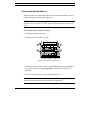
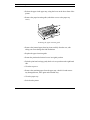
Loading Paper into the Printer
On the lower front of the printer there are two levers which control the
centering and the securing of the paper in the paper tray. On the inside of the
top cover, the template (identified ASF) illustrates the functions of these levers
for the paper loading operation (the numbers in brackets in the following
explanation represent the operation steps).
A
B
A: Paper securing lever - B: Paper centering lever
2-4
Getting Started
NOTE: For information on the types of paper you can use, the printing side,
manual insertion and the page layout, see the section entitled "Media
Characteristics" in Chapter 3.
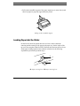
To load the paper:
• Move the lower lever B to the right (2 on the top cover template), to release
the lateral guides which keep the paper centred.
• Lower and move to the left the upper lever A (1).
Moving the levers to insert the paper
CAUTION: Take care not to force the levers, so that the paper guides hold
but DO NOT CRUMPLE the paper.
• To simplify paper loading, pull out the extendible rear guide on the paper
tray.
Extending the input tray guide
2-5
Getting Started
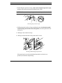
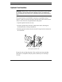
• Fan the paper thoroughly to reduce static build-up, and ensure the edges of
the paper are neatly stacked, so that the individual sheets feed smoothly
through the printer.
Fanning the paper
• Load the paper in the tray, pushing it in carefully until it stops against the
bottom of the printer.
Loading paper in the input tray
2-6
Getting Started
• Position the rear guide against the rear edge of the paper.
Closing the input tray
CAUTION: Do NOT force into the tray more paper than that permitted by
the physical limit of the printer casing (tray capacity approximately 70 x 21
lb sheets of paper).
Printing on both sides of the paper may increase the risk of misfeeds or paper
jams.
• Once you have inserted the paper, gently move the lower lever B to the left
to close the lateral guides and centre the paper (4).
• Move the upper lever A to the right and raise it (5).
Moving the levers to secure the paper
CAUTION: Make sure the paper feeds smoothly and that it is not held too
tightly nor that it has too much play.
2-7
Getting Started
Checking the Selector Switches
Selector switches are used on this printer to select functional features, such as
resident font used, character style, paper size...
CAUTION: Check that the Paper Size selector switch #3 is ON and that all
the other selector switches are OFF. This is the default setting for Letter size
paper.
To check the selector switches settings:
• Lift up the top printer cover (1).
• Open the selector switches cover (2).
1
1
2
2
Opening the selector switches cover
• Check that all the selector switches are OFF (DOWN position, according to
the top cover label), except the Paper Size selector switch #3 (ON: UP
position).
• Close the selector switches cover and then the top cover.
NOTE: For more information on the selector switches settings, see the section
entitled "Selector Switches Set-Up Procedure" in Appendix C.
2-8
Getting Started
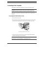
Connecting to the Computer
Your printer is connected to a computer by means of an interface cable.
CAUTION: The parallel interface cable is not included in the printer
package. Your dealer can supply you with the necessary interface cable.
This printer uses a parallel, Centronics-like interface with a 36-pin female
connector.
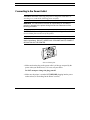
Connecting the Parallel Interface Cable
• Switch off first your printer.
• Plug the interface cable connector into the socket on the rear of the printer
(1), and close the spring clips on either side of it to hold it in place (2).
2
2
1
Inserting the parallel interface cable
• Connect the other end of the interface cable to the appropriate interface
connector socket (port) on your computer.
NOTE: For printer handling by the computer, see the "Installing the Windows
Printer Drivers" section and Chapter 3 "Operating the Printer".
2-9
Getting Started
Connecting to the Power Outlet
CAUTION: BEFORE connecting the printer to the power outlet and / or
switching it on, read all the following points carefully.
WARNING: The manufacturer declines all responsibility for accidents to
persons or damage to the printer arising from the non-observance of the
following procedure.
CAUTION: Make sure the power outlet supplies the voltage indicated on the
electrical data plate on the base of the printer.
WARNING: If the electrical data plate indicates a different voltage, call your
dealer immediately. DO NOT, UNDER ANY CIRCUMSTANCES, CONNECT
OR SWITCH ON THE PRINTER.
Electrical data plate
• Make sure that the plug on the power cable is of the type accepted by the
power outlet you intend to use; if it is not, call your dealer.
Do NOT attempt to change the plug yourself.
• Make sure the printer is switched OFF BEFORE plugging into the power
outlet socket (see "Switching On the Printer" section).
2-10
Getting Started
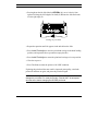
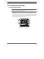
Switching On the Printer
After checking ALL the previous points, and ONLY if no further intervention
is required, plug into the power outlet socket and switch on the printer (the On
indicator lights).
Switching on the printer
Whenever the printer is switched on:
- It undergoes a series of internal checks.
- It any faults are found, the On-Line indicator on the operator panel will
flash rapidly. Should this happen, switch the printer off and then on again. If
the fault persists, call your dealer or the technical assistance service.
- A mechanical reset is executed and the switches selectors are read. The print
head carriage stops in the extreme right-hand position (rest position).
- If no faults are found, the printer will be in ON LINE condition (On and
On-Line indicators lit).
•
Switch off the printer.
NOTE: If you have had any problems, check that you have executed correctly
all the procedures described in this section; if you have, see the Chapter 5
"Troubleshooting".
2-11
Getting Started
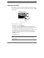
Installing the Print Head
The monochrome print head has an "ink detection" sensor which guarantees
optimum printing quality by allowing the timely replacement of the print head
or ink cartridge.
The following procedure applies to both print heads (monochrome and color).
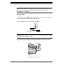
To install a print head:
• Switch on the printer.
CAUTION: Before installing a print head, check that the print head selection
lever matches the print head type you intend to insert.
• Lift up the top printer cover.
• Press the Install Cartridge button on the operator panel.
The print head carriage moves to the print head loading position, at the
centre of the carriage shaft (the On and On-Line indicators start flashing
alternately).
• Move the selection lever (located on the right side of the inside paper guide)
to the position that matches your print head type, according to the
indications engraved near the lever.
COLOR
BLACK
Print head selection lever
2-12
Getting Started
If the lever position does not match the print head type, the print head will
not return to its rest position and the On-Line and On indicators will flash
in sequence (On-Line twice followed by On once).
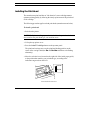
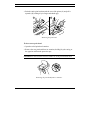
• Open the sealed print head container.
• Remove the print head from its container, holding it by the casing, at the
opposite side from the protective tape.
CAUTION: Do not touch the electrical contacts or sit the print head on them.
Removing the print head from its container
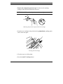
• Still holding the print head casing, remove the transparent protective tape,
pulling its tab end in the direction indicated by the arrow.
CAUTION: Do not touch the printing nozzles or sit the print head on them.
Removing the protective tape
2-13
Getting Started
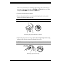
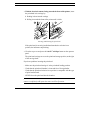
• With the electrical contacts facing towards the front of the printer, insert
the print head in its carriage by:
1. Pushing it down into the carriage
2. Pulling it towards the front of the printer until it clicks
1
2
Inserting and blocking the print head
If the print head is correctly installed and matches the selection lever
position, the indicators stop flashing.
• Close the top cover and press the Install Cartridge button on the operator
panel.
The print head carriage moves to the print head storage position, at the right
of the carriage shaft.
If you have problems inserting the print head:
- Make sure the print head carriage is in the print head loading position.
- Check that the print head chamber is clean and free of foreign bodies.
- Check that the print head selection lever position is compatible with the type
of print head inserted.
- NEVER force the print head into the chamber.
CAUTION: If you have problems when inserting the print head, always
remove it completely and repeat the entire insertion operation.
2-14
Getting Started
NOTE: To remove the print head, see the "Changing the Print Head" section in
the Chapter 4 "Maintenance".
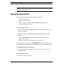
Running the Printer Self Test
Before running the printer test, please check the following:
-
Printer is switched off
Paper is loaded in the tray
Paper securing lever (A) is in the Lock position (upper position)
Print head is properly installed
To start the printer self test:
• Hold down the Install Cartridge button on the operator panel, while you
switch on the printer.
• Keep holding down the Install Cartridge button until the printer begins
printing.
- With a monochrome (black ink) print head, the automatic print test
produces 4 test sheets.
- With a color print head, a single test sheet is produced.
If there is no paper in the printer, the On-Line indicator will flash slowly. You
must load paper in the paper input tray and then press the Form Feed button.
To suspend the print test temporarily:
• Press the On-Line button (pressing this button a second time will cause
printing to resume).
To abandon the print test:
• You must switch the printer off.
2-15
Getting Started
Once the test is completed and the last sheet of paper expelled, the printer will
go automatically into ON LINE condition.
Check the print quality of the test, making sure that all the characters are
clearly defined and complete.
NOTE: If any problem occurs, see Chapter 5 "Troubleshooting" of this
manual for corrective actions.
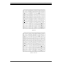
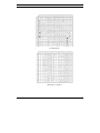
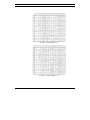
Printer Self Test Contents
Monochrome Print Head
If you have inserted a black print head, the print test will require at least four
sheets of paper (see the examples on the pages which follow).
• Check that all the characters are clearly defined and complete.
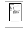
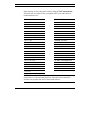
First Page
The first line of the print test contains information on the printer status:
- At the left hand margin: the resident (or selected) emulation
- At the right hand margin: the name, date of issue and level of the printer
firmware.
The second line of print test indicates the print head type and is followed by the
print head test which allows you to check whether any dots are missing. A list
of defective nozzles (if any) is indicated after the test. The defective nozzles are
identified by their number after the text: "Nozzles test Fail on". Otherwise, the
text "Nozzles test Pass" is printed.
NOTE: If there are defective nozzles, see the section entitled "Priming the
Monochrome Print Head" in Chapter 4 "Maintenance" for the possible
solutions to this problem. Then repeat the print test.
2-16
Getting Started
Then follows a list of the current feature settings (Set-Up), with a graphic
representation of the selector switches positions (small black rectangles: OFF
position, large black rectangles: ON position).
The currently selected character set table appears at the bottom of the test.
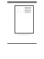
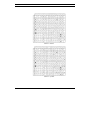
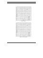
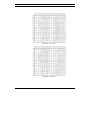
Second and Subsequent Pages
Samples of the resident (and, if present, optional) fonts in portrait and / or
landscape with all their attributes (see the section entitled "Selector Switches
Set-Up Procedure" in Appendix C and the section entitled "Resident Fonts" in
Appendix B).
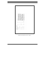
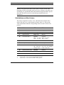
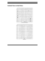
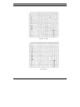
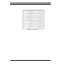
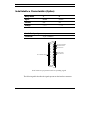
Color Print Head
If you have inserted a color print head, the print test will require one sheet of
paper. The print test will consist of three graphic samples (one for each of
basic colors in the print head) from which you can check the correct operation
of each group of nozzles.
• Check that the colored bands are bright and consistent in hue.
NOTE: In case of problems, refer to the Chapter 5 "Troubleshooting".
2-17
Getting Started
Example of monochrome print test: Page 1
2-18
Getting Started
Example of monochrome print test: Page 2
2-19
Getting Started
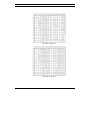
Example of monochrome print test: Page 3
2-20
Getting Started
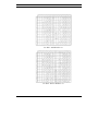
Example of monochrome print test: Page 4
2-21
Getting Started
26 27 28 29 30 31 32 33 34 35 36 37 38 39 40 41 42 43 44 45 46 47 48 49 50 51
1
2
3
4
5
6
7
8
9
10 11 12 13 14 15 16 17 18 19 20 21 22 23 24 25
(yellow)
(magenta)
(cyan)
(yellow)
(magenta)
(cyan)
(yellow)
(magenta)
(cyan)
26 27 28 29 30 31 32 33 34 35 36 37 38 39 40 41 42 43 44 45 46 47 48 49 50 51
1
2
3
4
5
6
7
8
9
10 11 12 13 14 15 16 17 18 19 20 21 22 23 24 25
Example of color print test
2-22
Getting Started
Installing the Windows Printer Drivers
Before you can print from a Windows 3.1x application, you must first install
the two Windows printer control programs (printer drivers) that are provided
on the Printer Drivers diskette.
NOTE: For more information about using Windows 3.1x, consult the
Microsoft Windows User's Guide.
The Digital DECwriter 110i Printer Driver is designed to print text and
grayscale graphics. The Digital DECcolorwriter 120ic Printer Driver is
designed to print color graphics.
NOTE: For more information about selecting the proper printer diver, see the
section "Selecting the Proper Windows Printer Driver" in Chapter 3.
For more information about the Printer Driver concept, see the section "Printer
Drivers" in Appendix C.
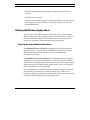
To install the Windows printer driver:
• Switch on your printer and PC.
• Insert the Driver diskette into your diskette drive.
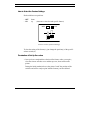
• Start up Windows on your PC and do the following:
1. In the Main window, double click on the Control Panel icon.
2-23
Getting Started
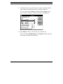
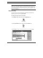
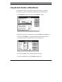
2. In the Control Panel window, double click on the Printers icon.
3. If the Installed Printers box is empty, go to the step 5 of these
instructions.
4. If the Installed Printers box already contains one or more printer
names, click on the Add>> button.
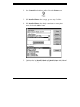
5. Check that the item Install Unlisted or Updated Printer in the List of
Printers box is highlighted and then click once on the Install... button.
2-24
Getting Started
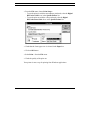
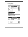
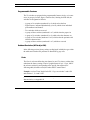
6. Check that the Install Driver dialogue box indicates the PC drive in
which you have inserted your Driver diskette. If it does not, change the
drive letter to the correct one.
7. In the Add Unlisted or Updated Printer window, select the Digital
DECwriter 110i driver.
The Digital DECwriter 110i driver then appears in the Installed
Printers box.
8. Repeat steps 5 to 7 to install the Digital DECcolorwriter 120ic
driver.
2-25
Getting Started
9. Check that the driver you intend to use is listed as connected to LPT1
port (or the port to which your printer is actually connected).
If it is not, click on the Connect... button and choose LPT1 (or the
port to which your printer is actually connected) in the Ports list.
10. In the Printers window, select the driver you intend to use.
Click on the Set As Default Printer in the Printers window and close
the window to complete the installation.
2-26
Getting Started
Running the Windows Print Test
Before printing from a Windows 3.1 application, you can check your drivers
are properly installed by printing the test files that are provided on the Driver
diskette.
To run the Windows print test:
• Insert the Driver diskette in your diskette drive.
• Run the Write program, (refer to your Windows manual for instructions on
running Write).
• From the File menu, choose Open.
• In the Drives box, select the drive where you have inserted the Printer
Driver diskette, for example A:.
• In the Directories box, open the tests sub directory:
- To run the print test with the monochrome print head, select the
testblk.wri file.
- To run the print test with the color print head, select the testcol.wri file.
2-27
Getting Started
• From the File menu, choose Print Setup...:
- To run the print test with the monochrome print head, select the Digital
DECwriter 110i driver in the Specific Printer list.
- To run the print test with the color print head, select the Digital
DECcolorwriter 120ic driver in the Specific Printer list.
• Check that the Letter paper size is selected in the Paper box.
• Click on OK button.
• Select Print... from the File menu.
• Check the quality of the print out.
Your printer is now set up for printing from Windows applications.
2-28
3
Operating the Printer
This chapter indicates the types and characteristics of the paper you can use,
how to insert documents and envelopes manually and how to print colour and
monochrome using the Windows printer drivers.
Media Printing Side
The printing side depends on the type of insertion. Knowing the printing side is
very useful for printing on envelopes or preprinted paper, such as letterhead
and overhead transparencies.
Automatic Insertion Printing Side
When using the Automatic Sheet Feeder, you have to load the pages with the
side you want to print on face down. If you are using letterhead, insert the top
of the paper first.
3-1
Operating the Printer
Manual Insertion Printing Side
When using the manual insertion (especially for the envelopes), you have to
load the pages with the side you want to print on face up. If you are using
letterhead, insert the top of the paper first.
Media Characteristics
The standard paper handling devices allow the use of a wide range of media
types and sizes. The printer drivers are specially designed to optimize printing
using such different media.
Paper Types
Most types of paper give good printing quality. Best results are obtained using
standard photocopy paper, which has a paper weight of between 18 and 24
lb/ream (70 to 90 g/m2).
CAUTION: Always test thoroughly the type of paper you intend to use. Substandard paper can affect the quality of printing.
Make sure the sheets are inserted in the paper tray to print on the correct
side of the paper (see indication arrow on paper wrapping, if present).
Printing on both sides of the paper may increase the risk of misfeeds or paper
jams.
3-2
Operating the Printer
Transparencies
The DECcolorwriter 120ic can be used to print color transparencies for use
with an overhead projector.
NOTE: Only Digital Equipment Corporation's LJ50X series transparency film
gives satisfactory results. The film is specially formulated to absorb the ink.
See Appendix A "Accessories and Options" for ordering information.
You can store or project transparencies 5 minutes after printing, but avoid
touching the images.
Inserting Transparencies
When inserting transparencies (manually or with the Automatic Sheet Feeder),
insert the glued edge first.
NOTE: See the section "Media Printing Side" in this chapter to properly insert
the transparencies in the printer.
3-3
Operating the Printer
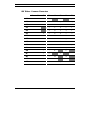
Dimensions
The following table contains the dimensions of the types of pages and
envelopes which you can use in your printer:
Single Sheets
Envelopes
US Letter
COM-10
8.5 in x 11 in
215.9 mm x 279.4 mm
US Legal
8.5 in x 14 in
9.5 in x 4.125 in
DL
215.9 mm x 355.6 mm
US Exec
7.25 in x 10.5 in
184.2 mm x 266.7 mm
A4
241.3 mm x 104.7 mm
220 mm x 110 mm
8.66 in x 4.33 in
C5
229 mm x 165 mm
9.02 in x 6.5 in
210 mm x 297 mm
8.26 in x 11.7 in
A5
210 mm x 148.5 mm
(landscape) 8.26 in x 5.85 in
Free
210 mm x 462.4 mm
8.26 in x 18.5 in
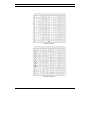
Standard size single sheets can be inserted either automatically from the paper
tray or manually through the front of the printer. Free format paper sizes must
be inserted manually.
Inserting Envelopes
Envelopes can only be inserted manually.
• Align the short side against the guide on the right of the insertion slot, with
the printing side face up and the sealing flap face down.
3-4
Operating the Printer
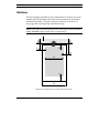
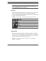
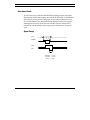
Print Area
The following figure and table give the measurements for the print area on the
standard page sizes handled by the printer (all measurements are indicated in
millimetres and inches). The printer can print a maximum of 60 lines on a
Letter page with 6 lpi linespacing with default settings.
NOTE: This value can be increased to 66 lines with specific selector switches
settings (D and E selector switches ON, see Appendix C).
1
T
L
R
B
W
M
Dimensions identification (1: Printer mechanical path)
3-5
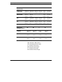
Operating the Printer
Dimensions/
Page Format
M
W
L
R
T
B
Letter/Legal
215.9 mm
203.2 mm
6.4 mm
6.4 mm
1 mm
12.7 mm
8.5 in
8 in
0.25 in
0.25 in
0.04 in
0.5 in
184 mm
184 mm
---
---
1 mm
12.7 mm
7.25 in
7.25 in
0.04 in
0.5 in
US Executive
A4
A5
210 mm
203.2 mm
3.4 mm
3.4 mm
1 mm
12.7 mm
8.26 in
8 in
0.134 in
0.134 in
0.04 in
0.5 in
210 mm
203.2 mm
3.4 mm
3.4 mm
1 mm
12.7 mm
8.26 in,
8 in
0.134 in
0.134 in
0.04 in
0.5 in
Dimensions/
Envelope Format
M
W
T
B
COM-10
241.3 mm
241.3 mm
1 mm
12.7 mm
9.5 in
9.5 in
0.04 in
0.5 in
229 mm
229 mm
1 mm
12.7 mm
9.02 in
9.02 in
0.04 in
0.5 in
220 mm
220 mm
1 mm
12.7 mm
8.66 in
8.66 in
0.04 in
0.5 in
C5
DL
-
3-6
M: maximum width of sheet
W: maximum print line length
L: minimum left margin
R: minimum right margin
T: minimum top margin
B: minimum bottom margin
Operating the Printer
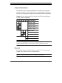
Inserting a Document Manually
To insert a document manually:
• With the printer switched on, position a sheet of paper on the paper guide,
aligning it with the corresponding guide at the left edge of the insertion slot.
Envelopes should be aligned with the guide on the right of the insertion slot.
They should be placed with their short side against the guide and with the
printing side face up and the sealing flap face under.
• Push the paper in until it stops against the feed rollers.
Manually inserting the paper
CAUTION: If you intend to insert single documents systematically, you must
first switch off the printer, set the selector C in its ON position and then
switch the printer on again (see the section entitled "Selector Switches Set-Up
Procedure" in Appendix C).
The document / envelope must not be crumpled or torn, otherwise it may jam
or even not be inserted.
3-7
Operating the Printer
• Press the Form Feed button; the paper will be fed in to the first print
position.
• Send the text to be printed.
Normally, after printing, the paper is expelled through the rear of the printer
into the paper output tray. However, if the paper is not ejected, press the
Form Feed button.
Printing with Windows Applications
All the features of the DECcolorwriter 120ic printer can be accessed within
Windows applications after having installed the two Printer Drivers which are
provided on the Driver diskette. These features allow you a great degree of
control over your printer, both monochrome and color printing.
Selecting the Proper Windows Printer Driver
The Digital DECwriter 110i driver is designed to print text and grayscale
graphics and allows you access to all installed fonts, including the resident
fonts and optional card fonts. This driver is to be used only with a
monochrome print head.
The Digital DECcolorwriter 120ic driver is designed to print color graphics.
It allows you access only to soft fonts (such as TrueType and other installed
scalable fonts) in the applications Characters menu, but the files using resident
fonts can nevertheless be printed using graphic mode. You can use this driver
with a monochrome or a color print head.
It is recommended to use the DECwriter 110i (monochrome) printer driver for
all text intensive printouts such as word processing files, so that you can
benefit from the faster printing of the resident printer fonts. You should use the
color printer driver primarily for printing graphics files.
3-8
Operating the Printer
NOTE: You cannot print the printer's resident landscape fonts (Courier and
Letter Gothic) in Windows landscape environment. To print in landscape, you
must use the Windows screen fonts (TrueType, bitmap) or programmes such
as FaceLift® (Bitstream).
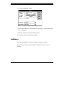
Printer Drivers Setup
To apply the Drivers setup to the Windows applications you intend to use,
change the parameters from the Control Panel.
To change the setup from the Control Panel:
• In the Main window, double click on the Control Panel icon.
• In the Control Panel window, double click on the Printers icon.
• In the Printers window, select the Printer Drivers you intend to change.
3-9
Operating the Printer
• Click on the Setup... button.
The selected Printer Driver setup window appears:
Digital DECwriter 110i setup window
DECcolorwriter 120ic setup window
3-10
Operating the Printer
Common Setup Parameters
The following parameter settings apply to both Digital DECwriter 110i and
DECcolorwriter 120ic Printer Drivers.
Resolution
- 300 dots per inch
- 150 dots per inch
- 75 dots per inch
This allows you to select the graphic density for images printing. Select the
higher resolution to obtain fine printing. By selecting the lower resolution, you
will increase the printing speed.
Paper Size
Several sizes are available to define sheets or envelopes formats (Letter, Legal,
Executive, A4, Envelope C5...).
The User Defined Size... option allows you to define your own specific page
format.
Select the measurement unit and specify the width and the length of the sheet
on which you intend to print. Respect the range specifications which are
indicated in the window.
3-11
Operating the Printer
Paper Source
- Auto Sheet Feeder
Select this option to print on the paper loaded
in the ASF - Automatic Sheet Feeder input
tray. This is the default setting.
- Envelope Manual Feed
Select this option to print on manually inserted
envelopes.
- Manual Feed
Select this option to print on manually inserted
sheets.
Orientation
- Portrait
- Landscape
This option allows you to change the printing orientation. The small icon (an
"A" in a page) near the buttons shows you what you have selected.
3-12
Operating the Printer
Specific Digital DECwriter 110i Setup Parameters
The following parameter settings apply only to the Digital DECwriter 110i
Printer Driver.
Memory
- None
- 256 KB
You have to select the 256 KB option if you have inserted the optional memory
card in your printer (see the Appendix A "Accessories and Options" for more
information about how to install it). Additional memory is necessary to load
soft fonts in your printer.
Cartridges
- None
- B:Prestige Elite
- RU:Times Nordic 8,10,12,14,30 pt
- TV:Nordic 8,10,12,14,30 pt
You have to select one of these fonts if you have inserted the corresponding
optional font card in your printer (see the Appendix B "Fonts" for more
information about the purpose of the font card, and how to install it). Then, the
corresponding font will appear as a resident font in the Font list within your
application.
3-13
Operating the Printer
HP Font Installer Window
The HP Font Installer is a tool for installing fonts temporarily or permanently
in your printer. You access this tool by clicking on the Fonts... button.
NOTE: For more information about the HP Font Installer, consult on-line help
by clicking on the Help... button.
3-14
Operating the Printer
Common Setup Options
The following options settings apply to both the Digital DECwriter 110i and
DECcolorwriter 120ic Printer Drivers.
• To access the Options window, click on the Options... button.
Digital DECwriter 110i Options window
Digital DECcolorwriter 120ic Options window
3-15
Operating the Printer
Dithering
This option defines the way that the colors are mixed for color printing or the
tonal range of the grayscale for monochrome printing.
- None
Only prints in seven colors with a color print
head and black and white with a monochrome
print head.
- Coarse
Default value for 300 dpi resolution. Produces
dark and thick printing
- Fine
Recommended for producing smoother
images.
Intensity Control
This option increases or decreases the darkness of graphics. For best results the
following recommendations are given:
- 1st choice
- Dithering = Fine
- Intensity: set between Normal and Lighter
- 2nd choice
- Dithering = Coarse
- Intensity: set at Normal
Print Quality
3-16
- Draft
Draft gives lowest resolution associated with
fastest print speed.
- Presentation
Presentation is used for printing grayscale or
color graphics. It gives the highest resolution
associated with the slowest print speed.
Operating the Printer
Paper Quality
- Plain Paper
- Transparency
It is important to select the type of paper being used, as the ink will behave
differently according to the surface.
Specific Digital DECwriter 110i Setup Options
The following options settings apply only to the Digital DECwriter 110i Printer
Driver.
Dithering
- Line Art
For black printing only, when well defined
borders between black and white and gray
shades are required. Not recommended for
scanned images.
Print Quality
- Letter Quality
Letter Quality gives the highest text
resolution and the slowest print speed.
3-17
Operating the Printer
Specific Digital DECcolorwriter 120ic Setup Options
The following options settings apply only to the DECcolorwriter 120ic Printer
Driver.
Color
Select this option and insert a color print head to obtain color printing.
NOTE: By deselecting this option, you can obtain monochrome printing by
using a monochrome print head. See the section "Monochrome Printing with
the DECcolorwriter 120ic Driver" in this chapter.
Print Quality
3-18
- Economy
Economy mode increases the print life of the
ink cartridge with only a slight reduction of the
Standard quality. Draft mode actually
provides the longest print life, but a greater
reduction in print quality.
- Standard
Standard is the default quality for 300 dpi
resolution. It offers a good compromise
between speed and resolution.
- High Quality
High Quality is the compromise between
Standard and Presentation.
Operating the Printer
Paper Quality
- Coated Paper
This type of paper will allow you to obtain good results for color printing, as
the paper will not absorb the ink in the same way as plain paper. You can use
all print qualities with this type of paper, except Draft. Nevertheless,
Economy mode may provide better results on some coated papers than
Standard mode.
Monochrome Printing with the DECcolorwriter 120ic Driver
Monochrome printing with the DECcolorwriter 120ic driver allows you to print
enhanced grayscale graphics and also gives you access to a larger choice of
Print Quality and Paper Quality options.
To print in monochrome using the DECcolorwriter 120ic driver:
• Deselect the color in the Options dialogue box
• Replace the color print head with the monochrome print head.
Monochrome printing can be achieved with the color print head which creates a
composite black by combining the colored inks. This, however, is not
recommended as the black color quality is low and it is a much slower and
costlier method of printing.
To switch to monochrome printing:
• Select the DECcolorwriter 120ic Printer Setup dialogue box (from the
Control Panel or from your application File menu).
3-19
Operating the Printer
• Click on the Options... Button.
• Click on the Color box to deselect the color printing (no cross indicates that
color is deselected).
• Install the monochrome print head in the printer.
You are now ready for monochrome printing.
Assistance
If you have any problems or require assistance, contact your dealer.
Keep the Drivers diskette with your printer documentation, for re-use, if
necessary.
3-20
4
Maintenance
This chapter describes basic maintenance operations you will be required to
perform during the printer's working life. It is important that you are familiar
with the different parts of your printer. Refer to "Introducing
DECcolorwriter 120ic Printer" before you attempt the operations described in
this chapter.
Basic Maintenance Operations
This printer is designed to require only minimum maintenance. However,
everyday use will give rise to a number of simple printer-care operations.
WARNING: If you detect serious mechanical damage to or a failure in the
printer, do not attempt to repair it yourself!
CALL THE DIGITAL SERVICE CENTER or your retailer. See the Digital
Customer Services Centers listing in the Chapter 5 "Troubleshooting", for
contact in your area.
4-1
Maintenance
Changing the Print Head
We recommend you to ALWAYS use your original supplier for print heads
and ink cartridges.
The print head is removed either to replace it or to ensure correct insertion, in
the case of faulty printing. The following section applies to both monochrome
and color print heads.
If dots or lines are not printed completely, remove the print head completely
and replace / reinsert it, and / or execute the print head cleaning and / or
PRIME operations (see the specific sections in this chapter).
When the an "end of ink" condition is indicated by the On-Line and On
indicators flashing alternately, you must either replace the ink cartridge
(monochrome print heads only) or, if necessary, change the entire print head.
WARNING: When the printer is already switched on and a print operation is
running, press the On-Line button to interrupt printing BEFORE opening the
top cover.
To return the printer to operating state, close the top cover and press the OnLine button.
To remove the entire print head:
• Press the Install Cartridge button on the operator panel.
• The print head carriage will move to the print head loading position, at the
centre of the carriage shaft.
• Open the top cover.
4-2
Maintenance
• Push the entire print head towards the rear of the printer (1) and pull it
upwards (2), holding it by its finger-and-thumb grip.
1
2
Removing the print head
To insert a new print head:
• Open the sealed print head container.
• Remove the new print head from its container, holding it by the casing, at
the opposite end from the protective tape.
CAUTION: Do not touch the electrical contacts or sit the print head on them.
Removing the print head from its container
4-3
Maintenance
• Still holding the print head casing, remove the transparent protective tape,
pulling its tab end in the direction indicated by the arrow.
CAUTION: Do not touch the printing nozzles or sit the print head on them.
Removing the protective tape
• Holding the print head by its finger-and-thumb grip and with the electrical
contacts facing towards the front of the printer, insert the print head in its
carriage by:
1. Pushing it down into the carriage
2. Pulling it towards the front of the printer until it clicks
1
2
Inserting and blocking the print head
If the print head is correctly installed and matches the selection lever
position, the indicators stop flashing.
4-4
Maintenance
• Close the top cover and press the Install Cartridge button on the operator
panel.
The print head carriage moves to the print head storage position, at the right
of the carriage shaft.
CAUTION: If you have set the printer to operate with a color print head
(print head selection lever towards the inside of the printer) and the print
head you have inserted is a monochrome one, the print head carriage will not
return to its rest position and the On-Line and On indicators will flash in
sequence (On-Line twice followed by On once). You must change the
position of the print head selection lever. This lever will only move if the print
head carriage is in the loading position.
If the indicators flash with the sequence On-Line five times followed by On
once, this indicates that the print head inserted is not compatible with the
currently loaded printer driver options.
If you have problems inserting the print head, always remove it completely and
repeat the entire insertion operation, checking the following:
• Make sure the print head carriage is in the print head loading position.
• Check that the print head chamber is clean and free of foreign bodies.
• Check that the print head selection lever position is compatible with the type
of print head inserted.
• NEVER force the print head into the chamber.
4-5
Maintenance
Cleaning the Print Head
If you encounter printing quality problems, run the self print tests which are
described in Chapter 2. This test will demonstrate whether the print head
nozzles are operating properly or not. If you find that there are problems,
perform the following steps. The following section applies to both monochrome
and color print heads.
To clean the print head:
• Remove the print head from the printer.
• Clean the electrical contacts on the print head and on the print head carriage
with the brush supplied with the storage box.
CAUTION: If there are traces of ink on the electrical contacts, you MUST
NOT use the brush, otherwise you may permanently damage them. Instead
use an absorbant material, such as blotting paper, to remove the ink traces
from the contacts.
• Insert the print head in the printer and run the print test again.
If you are still unable to make the print head operate correctly, do the
following:
• Dampen a paper tissue and then squeeze it to remove excess water.
• Remove the print head from the printer.
• Holding the print head with the printing nozzles facing downwards, blot it
against the paper tissue, pressing lightly. Repeat this on different areas of
the paper tissue until the ink nozzles are clean.
• Insert the print head in the printer and run the print test again.
If the print head still does not operate correctly, you must change, or if it is
monochrome, prime the print head (see the specific sections in this chapter).
4-6
Maintenance
Replacing the Monochrome Ink Cartridge
When the ink detection feature signals an "end of ink" situation (the On-Line
and On indicators flashing alternately, a print head being installed), you must
either replace the monochrome ink cartridge, or change the entire print head.
The use of Digital replacement ink cartridges provides you with the most cost
effective printing solution available.
After using a number of replacement ink cartridges (up to 10, depending on
work load and storage), your printer may begin to experience some degradation
in print performance, such as excessive smudging or missing dots. If this is the
case, you should replace the print head.
NOTE: See the Appendix A "Accessories and Options" for the order numbers
for the set of 2 ink cartridges and the print head.
• Press the Install Cartridge button, to move print head carriage to the print
head loading position.
• Open the top cover of the printer.
• To remove the ink cartridge, move aside the plastic tab (1), leaving the print
head casing in its carriage and pull out the ink cartridge (2).
2
1
Removing the ink cartridge
4-7
Maintenance
• Remove the transparent protective tape from the new ink cartridge,
pulling it in the direction indicated by the arrow.
CAUTION: Do NOT touch the ink pad area on the cartridge.
Removing the protective tape from the ink cartridge
• Insert the new cartridge in the print head casing immediately, pushing gently
until it clicks into place.
Inserting the ink cartridge
• Close the top cover of the printer.
• Press the Install Cartridge button.
4-8
Maintenance
The print head carriage moves to its rest position.
If the new ink cartridge is not inserted correctly, the On-Line and On
indicators will flash alternately. You must repeat the replacement operation
completely.
CAUTION: Always keep the ink cartridges sealed until they are to be used.
Do NOT attempt to re-ink the cartridge, as this damages the print head and
the printer.
NOTE: If the quality of printing is not optimum, try priming the print head
(see the following).
Priming the Monochrome Print Head
You need to prime the monochrome print head to clear the ink nozzles. This
operation applies only to monochrome print head.
If, after inserting a new print head or during a printing operation, the print
quality is not optimal or deteriorates, prime the print head to improve it. Poor
print quality is usually caused by air bubbles which block one or more of the
print head nozzles; priming will clear any blockage.
To prime the print head, proceed as follows:
• Set the printer OFF LINE (pressing the On-Line button), to move the print
head carriage to its rest position.
• Open the top cover of the printer.
4-9
Maintenance
• Pressing down the ink slide (labeled <PUSH>) (1), move it slowly from
right to left along the full length of its shaft (2). Release the slide and return
it to the right edge (3).
1
2
3
Priming the print head
• Repeat the operation until ink appears in the tube below the slide.
• Press Install Cartridge to move the print head carriage to the head loading
position, and repeat the above operation to empty the tube.
• Press Install Cartridge to return the print head carriage to its rest position.
• Close the top cover
• Press On-Line to return the printer to ON LINE condition.
If priming the print head does not result in improved print quality, switch the
printer off and then on again, and prime the print head again.
WARNING: Priming MUST NOT be repeated systematically, as it will
damage the print head. For used print heads, it should ONLY be attempted
as a last resort, before changing the ENTIRE print head.
4-10
Maintenance
Transporting the Printer
Although your DECcolorwriter 120ic printer is small, it is not a portable
printer and you need to take care when transporting it.
To prepare your printer before transporting it:
• Remove the print head and store it into the storage box to prevent it from
drying out.
• Detach the interface cable and unplug the power cable.
• Remove paper from the paper input and output trays.
• Tape the paper insertion guide to the lower front of the printer.
• Repack the printer in its original packing materials.
4-11
Maintenance
Storing the Print Heads
The print head storage box is provided to store safely the print head not in use.
This box has 2 slots, one for the monochrome print head and the other for the
color print head.
When removing a print head from its sealed container or from the printer, you
should store it immediately in the storage box to ensure it is properly protected
and will not dry out.
1
Storing a print head
Inside the storage box, there is a small brush (1) which you can use to clean
gently the electrical contacts on the print head or the print head carriage, if
necessary.
WARNING: You should not use the brush to clean the ink nozzles, as this
could permanently damage them.
4-12
4-13
5
Troubleshooting
Information about troubleshooting in this chapter provides solutions to most of
the common problems. However, if the printer does not operate correctly after
following the recommendations, contact your local Digital Services Center or
retailer where you bought your printer, see the list below.
Contacting your Digital Services Center
Before calling for support, you should prepare the following information:
- The serial and model number of the printer, which is found on the electrical
data plate (on the underside of printer).
- A summary of the problem.
- The details of your configuration: hardware and applications software.
- The operator panel indicator Error Status or specific failure symptoms.
5-1
Troubleshooting
Returning the Printer for Maintenance
If you are asked to return the printer for repair, please follow the instructions
below to ensure you receive the best and most efficient service possible.
To prepare returning the printer:
• Prepare the printer for transport, see Chapter 4.
• Include your name, address and your telephone number.
• Enclose the following details:
- The complete configuration details when problems occurred, including
cable type, interface type, application software used.
- The problem description.
- A sample of the printing problem, if appropriate.
- A copy of purchase receipt to establish the warranty period.
Digital Customers Services Centers
(*) indicates free numbers.
Country
Phone Number
U.S.A.
1-800-354-9000 *
Australia
008 252277 *
Austria
1-86630-2000
Belgium
02-7297744
Canada
5-2
English
1-800-267-5251 *
French
1-800-267-2603 *
Denmark
80301005
Finland
800-2878
France
1-46873109
Germany
0130-7702
Greece
1-6821980
Troubleshooting
Country
Phone Number
Crete
237576
Thessaloniki
423760
Hungary
01-1810966
Eire
01-381216
Israel
09-593300
Italy
1-678-20062
Japan
0120-113035 *
Korea
2-7991333
Netherlands
030-832888
New Zealand
080 080 1272 *
Norway
2-2768600
Portugal
01-3889100
Singapore
3366129
Spain
Barcelona
03-4012222
Madrid
01-583-4257
Sweden
08-988835
Switzerland
155-5544 *
Taiwan
080 211 393 *
Thailand
66-254-8191
UK.
0256-57122
Windows Warnings
For more information about Windows warnings, consult either the on-line help
(provided in the Printer Driver), or the "Printing" section of the
"Troubleshooting" chapter in the "Getting Started with Microsoft Windows"
manual.
5-3
Troubleshooting
Indicators Warnings
On-Line and On indicators flashing alternately
State caused by end of ink condition. Load a new print head, and then return
the printer to the ON LINE operating state by pressing the Install Cartridge
button.
On-Line and On indicators flashing with the sequence On-Line twice
followed by On once
State caused by incompatibility between the type of print head inserted and the
position of the print head selection lever. Load the correct type of print head
and / or position the print head selection lever correctly, and then return the
printer to the ON LINE operating state by pressing the Install Cartridge
button.
On-Line and On indicators flashing with the sequence On-Line five times
followed by On once
State caused by an incompatibility between the type of print head inserted and
the printer driver loaded. Insert the correct type of print head, and then return
the printer to the ON LINE operating state by pressing the Install Cartridge
button.
On-Line indicator flashing slowly
State caused by lack of paper during a printing operation. Load paper and then
return the printer to the ON LINE operating state by pressing the On-Line
button.
On-Line indicator flashing rapidly
State caused by an operating failure.
5-4
Troubleshooting
Solving Problems
Contents
Installation Problems ...................................................................... 5-6
Missing or Damaged Parts.................................................................. 5-6
Printer Does Not Switch On ............................................................... 5-6
No Initial Mechanical Reset ............................................................... 5-6
Print Test Did Not Run....................................................................... 5-7
Problems with Connection to Computer ............................................. 5-7
Paper Problems .............................................................................. 5-8
No Paper ............................................................................................ 5-8
Paper Does Not Load.......................................................................... 5-8
Single Sheets / Envelopes Not Loaded (or Loaded Incorrectly) .......... 5-9
Paper Jams or Tears............................................................................ 5-9
Printing Problems ......................................................................... 5-11
Printer Does Not Print / Receive Data .............................................. 5-11
Printing Stops ................................................................................... 5-12
Printed Characters Are Faint............................................................. 5-12
Printing with Missing Dots ............................................................... 5-13
Poor Print Quality............................................................................. 5-13
5-5
Troubleshooting
Installation Problems
Missing or Damaged Parts
• Contact your dealer immediately.
Printer Does Not Switch On
No power supply (no indicators are on).
• Check that the printer is switched on.
• Check that the power cable is inserted correctly in the printer and in the
power outlet.
• Check that power is supplied through your power outlet.
No Initial Mechanical Reset
At power-on, the print head carriage does not move.
• Check that the carriage path is not obstructed.
• Try switching the printer off and then on again.
• If the On-Line indicator is flashing rapidly, there is a failure on the main
board; call a Digital sales representative or your retailer.
5-6
Troubleshooting
Print Test Did Not Run
• Switch off the printer, then switch it on again, remembering to hold down the
On-Line button until the print test starts.
• If the carriage does not move, check that its path is not obstructed.
• If the On-Line indicator flashes slowly and there is no paper in the printer;
load paper in the paper input tray and press the Form Feed button.
• If the On-Line indicator flashes slowly and there is paper in the printer: the
paper centering guides may prevent the paper from loading; move the lever B
slightly to the right to open the centering guides and release the paper, and
then restart the print test (see the Paper Does Not Load section below).
• If the On and On-Line indicators flash alternately:
- Check that the print head is inserted correctly and matches the position of
the print head selection lever. Check the lever position and, if necessary,
remove and reinsert the print head. Remember to press Install
Cartridge before and after either of these procedures.
- The print head ink cartridge needs replacing; follow the instructions given
in the section entitled Changing the Print Head / Replacing the
Monochrome Ink Cartridge in the Chapter 4, to insert / replace the print
head / ink cartridge.
Problems with Connection to Computer
• Check that your interface cable is of the correct type.
• Make sure you have fixed the interface connectors properly both to the
printer and to the computer.
• Check that you have configured your application correctly (see your
application manual).
5-7
Troubleshooting
Paper Problems
NOTE: Always use paper in perfect condition and within the specifications
defined (see Chapter 3).
No Paper
If, on a print command or during a print operation, there is no paper to load in
the printer, the On-Line indicator flashes slowly.
• To clear this condition, load more paper in the paper tray or, if the manual
paper feed feature is selected, feed paper manually and press Form Feed.
Refer to Chapter 3 for details about manual paper feeding.
Paper Does Not Load
• Check that the size and weight of the paper used are within the limits
allowed.
• Make sure the paper is feeding straight.
• Make sure that you are trying to load from the selected paper device
(selector switch C OFF for paper feed from tray, ON for manual feed).
• Check that the paper guides are not too tight against the paper stack. If they
are, open them by moving the lever B slightly to the right. See also the
Paper Jams section below.
• Paper jamming (see below).
5-8
Troubleshooting
Single Sheets / Envelopes Not Loaded (or Loaded Incorrectly)
The paper / envelope has been inserted incorrectly (not aligned with the correct
margin indicator - left for single sheets, right for envelopes).
• If your application program does not send a paper feed command, position a
sheet of paper manually and press Form Feed.
• Remove all the paper from the paper tray, fan it thoroughly, and then reload
it, aligning it correctly in the tray.
Paper Jams or Tears
If the page has almost finished printing:
• Set the printer OFF LINE.
• Release the paper in the paper tray, using the levers on the lower front of the
printer.
• Open the top cover and remove the jammed paper.
• To resume printing, close the top cover and the paper tray, and then press
On-Line.
If the paper jams inside the paper tray:
• Switch off the printer.
• Open the top cover.
• Move the print head carriage from its rest position, sliding it carefully along
its shaft.
• Move the print head selection lever to the COLOR position (if it is not
already in this position).
5-9
Troubleshooting
• Release the paper in the paper tray, using the levers on the lower front of the
printer.
• Remove the paper insertion guide (which also serves as the paper tray
cover).
Removing the paper insertion guide
• Remove the jammed paper, drawing it out carefully from the rear, with
taking care not to damage the feed mechanism.
• Replace the paper insertion guide.
• Return the print head selection lever to its original position.
• Push the print head carriage gently back to its rest position at the right hand
side.
• Close the top cover.
• Remove the remaining paper from the paper tray, check it for and remove
any damaged sheets, fan it again and reload the tray.
• Close the paper tray.
• Switch on the printer.
5-10
Troubleshooting
CAUTION: The most common cause of paper jamming inside the paper tray
is the addition of paper to the tray when it is not empty and / or the incorrect
loading of paper.
When adding paper to the paper tray or after removing jammed paper,
ALWAYS remove any paper already in the tray, fan it, and reload it all as a
single pack.
Printing Problems
Printer Does Not Print / Receive Data
• Check that the printer is switched on (On indicator lit).
• Check the physical (cables) and logical (application and printer driver)
connections between the printer and computer.
• Check that the printer is ON LINE (On-Line indicator lit), and that the
computer is switched on.
• Check that you have removed the transparent protective tape from the print
head.
• Press Form Feed. If data is in the printer input buffer, this will complete
the printing of the contents of the print buffer. In some cases, under DOS,
data is sent to the printer with no Form Feed command, consequently data
may be ready for printing but the printer is waiting for the Form Feed
command before it starts printing.
If the carriage does not move and the On-Line indicator is flashing rapidly:
• Switch the printer off, check for and remove the cause of any blockage and
then switch the printer on again.
If the On-Line indicator flashes slowly:
• Check that the paper loads correctly.
5-11
Troubleshooting
If the On and On-Line indicators flash alternately:
• Check that the print head is inserted correctly and matches the print head
selection lever position.
• The print head / ink cartridge may need replacing; follow the instructions
given in the section entitled Changing the Print Head / Replacing the
Monochrome Ink Cartridge in the Chapter 4, to insert / replace the print
head / ink cartridge.
Printing Stops
If the On-Line indicator flashes slowly and there is no paper in the printer:
• Reload the paper tray or, if the manual paper feed feature is selected, feed
paper manually and press Form Feed. Refer to Chapter 3 for details about
manual paper feeding.
If the On and On-Line indicators flash alternately, the print head / ink
cartridge needs replacing:
• Follow the instructions given in the sections entitled Changing the Print
Head / Replacing the Monochrome Ink Cartridge in the Chapter 4, to insert
/ replace the print head / monochrome ink cartridge.
Printed Characters Are Faint
• Prime the print head to clear the ink nozzles, see Chapter 4.
5-12
Troubleshooting
Printing with Missing Dots
• Prime the print head to clear the ink nozzles, or replace the print head.
• Clean the electrical contacts on the print head and those in its chamber (see
Chapter 4).
Poor Print Quality
• Prime the print head to clear the ink nozzles.
• Turn over the paper pack in the paper tray, so as to print on the other side of
the paper.
• Make sure you are using good quality paper.
5-13
A
Accessories and Options
This appendix lists the accessories and optional items that are available on
request as well as their order numbers. It also describes how to insert a
memory card in the printer.
Accessories
Monochrome Print Head and Ink Cartridge
The monochrome print head, consisting of a printing unit and a replaceable ink
cartridge, is available packaged as follows:
• Set of 1 complete monochrome print head (printing unit
+ ink cartridge) and 1 monochrome ink cartridge
• Set of 2 monochrome ink cartridges (400 pages life each)
LJ50X-AB
LJ50X-AC
A-1
Accessories and Options
Color Print Head
The color print head, consisting of a single unit, including the printing unit and
the ink cartridge (not replaceable), is available packaged as follows:
• Set of 1 color print head (200 pages life)
LJ50X-AK
Transparencies
Digital transparencies are available in two sheet sizes:
• Letter size (50 sheets box)
LJ50X-AE
• A4 size (50 sheets box)
LJ50X-AF
Options
PCMCIA Emulation Card
• IBM Proprinter X24 / EPSON LQ 850 multi-emulation
LJ11X-IE
PCMCIA Font Cards
Each font card is supplied with a booklet which illustrates the font card
contents and explains the font selection procedure.
• Font Card B
Prestige Elite / 7-10 pt / 16.67-12 cpi
Letter Gothic / 12 pt / 12 cpi
Line Draw
• Font Card R,U Times Nordic / 8-10-12-14-30 pt / PS
• Font Card T,V Nordic / 8-10-12-14-30 pt / PS
A-2
LJ50X-CH
LJ50X-CJ
LJ50X-CK
Accessories and Options
PCMCIA RAM Card
Other standard PCMCIA Type 1 cards up to 4 Mbytes, available on the
market, can be used.
• 256 KB card
LJ50X-DB
Serial Interface
• User-installable kit for EIA RS 232C / V24 interface
LJ50X-SI
Parallel Data Cables
• 10 ft parallel shielded cable
BC19M-10
• 6 ft parallel shielded cable
BC19M-06
A-3
Accessories and Options
Optional Card Insertion
WARNING: Always insert / remove the optional card with the printer switched
off. Insertion / removal with the printer switched on and / or operating will
cause a hardware reset and the risk of damaging the printer and the optional
card.
The optional memory card (256 KB) is necessary to expand the memory
capacity, so that you can load soft fonts. Optional cards can be inserted, one at
a time, in the slot on the rear right hand side of the printer.
• Open the optional card slot cover (1).
• Insert the optional card so that the symbol ∫ on the label, indicating the
insertion direction, is facing outwards (2).
• Push the optional card down into the slot until it snaps into the connector on
the main board.
1
2
Inserting the optional card
Do not force the card into the printer. If the card does not insert smoothly,
check that it is compatible with your printer, and that you are inserting it
correctly.
A-4
Accessories and Options
Using the Serial Interface within Windows
If you intend to use the serial interface option and print from a Windows
environment, you have to specify this connection in your printer Setup.
• In the Printers dialogue box, click on the Connect... button.
• Select the serial port you intend to use (usually COM 1) in the Ports box.
• Click once on Settings... to check that the transmission parameters are
correct for the type of serial transmission you intend to use.
• Click once on OK to close each dialogue box you open.
• Click once on Close to close the Printers dialogue box.
A-5
B
Fonts
This appendix describes the characteristics of the resident and optional fonts
available.
Introduction
A "font" is a group of characters which all belong to the same character set and
have the same typeface, the same style, the same height and print pitch and the
same stroke weight.
Your printer can use fonts from the following sources:
• Resident fonts, which are always available
• Optional fonts on memory cards
• Scalable fonts resident in your MS-Windows application
B-1
Fonts
Resident Fonts
The fonts resident in the printer have the following characteristics (the values
in bold face are the base values):
Typeface: Courier
Orientation
Portrait
Portrait
Landscape
Landscape
Character Set *
CP 437
International
CP 437
International
CP 437
International
CP 437
International
Horizontal
Spacing
Fixed
Fixed
Fixed
Fixed
Pitch (cpi)
5 - 8.33
10 - 16.67
20 - 33.34
5 - 10 - 20
10 - 16.67
20 - 33.34
10 - 20
Height (dots)
6 - 12
6 - 12
6 - 12 - 24
6 - 12 - 24
Style
Upright
Italic
Upright
Italic
Stroke Weight
Medium/Bold
Medium/Bold
Medium/Bold
Medium/Bold
* Default character set; other resident character sets are available (see Appendix D).
Typeface: Letter Gothic
Orientation
Portrait
Portrait
Portrait
Landscape
Character Set *
CP 437
International
CP 437
International
CP 437
International
CP 437
International
Horizontal
Spacing
Fixed
Fixed
Fixed
Fixed
Pitch (cpi)
5 - 6 - 10 - 12
20 - 24
6 - 12 - 24
8.33 - 16.67
33.34
10 - 16.67 - 20
33.34
Height (dots)
6 - 12
6 - 12
4.75 - 9.5
4.75 - 6 - 9.5
12 - 19 - 24
Style
Upright
Italic
Upright
Upright
Stroke Weight
Medium/Bold
Medium/Bold
Medium/Bold
Medium/Bold
* Default character set; other resident character sets are available (see Appendix D).
B-2
Fonts
Typeface: Times Nordic
Orientation
Portrait
Portrait
Character Set *
CP 437 International
CP 437 International
Horizontal Spacing
PS
PS
Height (dots)
6 - 12
6 - 12
Style
Upright
Italic
Stroke Weight
Medium/Bold
Medium/Bold
* Default character set; other resident character sets are available (see Appendix D).
Typeface: Book Face Times +
Orientation
Portrait
Portrait
Character Set *
CP 437 International
CP 437 International
Horizontal Spacing
PS
PS
Height (dots)
4 - 5 - 6 - 7 - 8 - 10 - 12 - 14
4 - 5 - 6 - 7 - 8 - 10 - 12 - 14
Style
Upright
Italic
Stroke Weight
Medium/Bold
Medium/Bold
+ Not available if a non-Western character generator is selected (see Appendix D).
* Default character set; other resident character sets are available (see Appendix D).
Typeface: Linea +
Orientation
Portrait
Portrait
Character Set *
CP 437 International
CP 437 International
Horizontal Spacing
PS
PS
Height (dots)
4 - 5 - 6 - 7 - 8 - 10 - 12 - 14
4 - 5 - 6 - 7 - 8 - 10 - 12 - 14
Style
Upright
Italic
Stroke Weight
Medium/Bold
Medium/Bold
+ Not available if a non-Western character generator is selected (see Appendix D).
* Default character set; other resident character sets are available (see Appendix D).
B-3
Fonts
Line Draw
This font is available ONLY in portrait orientation with 12 cpi spacing, 12 dot
height and medium stroke weight.
The standard print test contains a print sample (the default character set) of all
the resident fonts.
Before loading soft fonts in your printer, you must expand the memory
capacity, using the optional 256 KB memory card (or standard PCMCIA Type
1 memory cards).
NOTE: The instructions for the installation and use of the optional font cards
and soft fonts are supplied with the individual options.
Two independent fonts, primary font and secondary font , are always active
in the printer. Their characteristics can be modified independently, one at a
time. You can alternate between the currently active primary and secondary
fonts using the command codes "SI" and "SO" (see Appendix E "Command
Codes").
B-4
Fonts
Font Handling Using Command Codes
Down-Line Loading of Fonts
This section contains a summary of the command codes which handle the
optional fonts available in the font cards. For further and more detailed
information refer to the manual supplied with the specific font card.
With the optional font card inserted and selected, you can use the following
command codes to assign a name and ID to the font required, load and store it
in the printer and clear it.
ASCII
Decimal
Hexadecimal
Description
ESC ) s n W ..
27 41 115 n 87
1B 29 73 n 57
Name of Font to be loaded
ESC * c n D
27 42 99 n 68
1B 2A 63 n 44
ID Assignment for Font to be loaded
ESC * c n E
27 42 99 n 69
1B 2A 63 n 45
ASCII Code of Character to be loaded
ESC ( s n W ..
27 40 115 n 87
1B 28 73 n 57
Bit Map of Character to be loaded
ESC * c 0 F
27 42 99 48 70
1B 2A 63 30 46
Clears all Fonts loaded
ESC * c 1 F
27 42 99 49 70
1B 2A 63 31 46
Clears all Temporary Fonts loaded
ESC * c 2 F
27 42 99 50 70
1B 2A 63 32 46
Clears Last Font loaded
ESC * c 4 F
27 42 99 52 70
1B 2A 63 34 46
Stores Font loaded as Temporary
ESC * c 5 F
27 42 99 53 70
1B 2A 63 35 46
Stores Font loaded as Permanent
ESC ( n X
27 40 n 88
1B 28 n 58
Selects Primary Identifier for Font
loaded
ESC ) n X
27 41 n 88
1B 29 n 58
Selects Secondary Identifier for Font
loaded
B-5
C
Printer Controlling
The first part of this appendix gives you some useful information about the
way your printer interfaces with your system and applications. Read this
section to clarify any initial problems or for more insight into some features of
the printer Set-Up and the software installation process. The second part of this
appendix is dedicated to setting up the printer using the selector switches. The
third section explains how to carry out hexadecimal printing.
The Communication Protocol
One of the most crucial things which affects the correct working of your printer
and computer is the setting of the communication protocol. If the protocols do
not match, you will not obtain satisfactory results or even none at all.
It is not difficult to set the protocols correctly, but it is absolutely necessary
that the communication parameters in the printer and in the computer be
compatible.
C-1
Printer Controlling
NOTE: The information given in this section refers to MS-DOS environment
as it is the most widely-used. For other environments the same logic remains
true, but see the related documentation for details.
The indications given here are sufficient for MS-DOS up to release 6.0.
Parallel Interface
With the resident parallel interface, you do not have to do anything, as the only
variable parameter is the data format "word length", which, in the PC, is
always set to 8. This is the printer's default setting.
The parallel communication protocol can be activated using the following MSDOS command (consult your MS-DOS manual for the complete syntax):
MODE LPT1:(characters per line),(line spacing),P
To address the parallel printer interface as a logical output device, you can use
one of the following names: LPT1 or PRN. It is also possible to redirect output
prepared for the parallel interface to a serial interface, using the command:
MODE LPT1:=COMn:
Serial Interface
If you install the optional serial interface in your printer, to use it you must pair
up the printer's protocol with the one in your computer. The protocol can either
be programmed in the printer (for the parameters and programming procedure,
see the specific sections in this chapter), or you can adapt your computer to the
printer setting using the command:
MODE COMn:(baud),(parity),(word length),(stop bits),p
where "n" is the number (usually 1) of the addressed interface board, and baud
requires only a two digit number.
C-2
Printer Controlling
Printing Methods within DOS Environment
Once your printer and computer are connected correctly and the logical link
established, you can use the printer to its full extent. If you ran the print test
when you installed the printer, you saw the printer execute an internallycommanded operation. You can now have the printer print something on your
command. The following section contains some basic operations, which do not
require the processing of an application.
CAUTION: For all following operations make sure the printer is switched
on, with paper and print head loaded, and that it is ON LINE.
Printing a Text Screen
The easiest way to obtain a print-out is a screen dump. Let us presume you are
in your operating system and have made a Directory Listing with the command
DIR. If you want this list printed out for future reference, simply press SCR
PRT (Print Screen) on your PC keyboard (on some PCs, SHIFT is also required
simultaneously). The printer will start to print everything you see on the screen
exactly as you see it. You regain the control of your keyboard when the
necessary data transmission to the printer is finished.
NOTE: This method works from within all applications which handle the
screen in text mode (certain types of graphics may not be printed).
Printing Text Files
The most common printer operation is the printing of a complete text or data
file. When you have printable files, prepared by your editor, word processor,
database etc., you can send them to print using one of the following methods.
NOTE: A printable file is one which contains only the data to print and
probably appropriate printer control commands and is basically line oriented
(closes each printable line with CR/LF). Printing with applications is explained
in a specific section in this chapter.
C-3
Printer Controlling
When you have the system prompt, type one of the following commands:
print {filename}
This invokes the print utility of your operating
system. The first time you call it, it will ask you
to confirm or change the output port. For details
about file spooling etc., see in your DOS Manual.
NOTE: This command executes a Form Feed automatically after each
document is printed.
type {filename}>prn
This utility normally lists the contents of a file on
your screen, but in this case redirects it to the
printer, allowing you to interrupt printing with
CTRL - C, as you would do for the screen. This
command will execute an automatic Form Feed at
the end of a document only if it is included in the
document itself.
copy {filename}/B prn This command also sends the file to the printer. If
you send graphic or DLL (i.e. fonts) files to the
printer, remember use the optional "/B" parameter
in the command to override any End Of File
(=EOF =26D) command, which otherwise would
cause DOS to discontinue the data transfer.
NOTE: For more detailed information about these commands, consult your
MS-DOS manual.
C-4
Printer Controlling
Software Applications
The printer performance can be controlled using software programs developed
for a wide variety of applications, such as word processor, spread sheet, data
base, graphics, etc. The software transmits the operating information to the
printer in two different ways, with:
- The Printer Driver: the part of the program which controls the selected
printer
- Incorporated commands: inserted directly in the text to be printed.
Printer Drivers
To print a document using a software application program, you must have a
computer, an application program and a printer. Just as you must have an
interface cable to connect your computer and printer, so must you also have a
driver which interfaces your application program with your printer.
A Printer Driver is a software program written specifically for an application
and a particular printer model. The Printer Driver controls the printer behavior,
loading information from your software and transmitting it to the printer to
create a document. When you select the print attributes (bold, italic, etc.) for a
document, the software transmits the corresponding codes to the Printer Driver.
The driver interprets the software codes and sends an equivalent series of
commands to the printer (see Appendix E "Command codes"). The printer
prints the document with the print attributes desired.
The Printer Driver transmits both characters, numbers and / or symbols for
printing and also instructions on how the data received should be printed. It
has, however, two limitations:
C-5
Printer Controlling
Due to the application software
A driver can handle only the information transmitted to it by the application
program. If, for example, the application does not handle bold-face, your
printer will never print in boldface, even though it is capable of doing so.
Inherent to the driver
Only the information contained in the driver program can be acted upon. If, for
example, the driver program does not contain the instructions for boldface,
your printer will never print in boldface, even though it is capable of doing so.
To overcome the second limitation, and allow you to use all your printer's
features, the manufacturer has developed and will continue developing, in
collaboration with software houses, specific Printer Drivers for the most
common software application packages.
To optimize the use of your printer, use its specific driver which is either:
- In a diskette supplied with the printer
- Inserted directly in your software application program (just select your
printer name in the list of printers available), or in a supplementary printer
driver disk (e.g. Printer Driver Library).
If you cannot find the specific driver for your application program, contact
your dealer for information on its availability. In the meantime, you can use a
driver corresponding to the emulation in your printer, even though this will
probably not exploit fully all your printer's functions and features.
NOTE: The driver you select must be compatible with the resident printer
emulation (HP PCL III+) or with one or other of the optional emulations (IBM
Proprinter X24 or EPSON LQ 850) installed using an emulation card (see
Appendices A and D, and the specific documentation supplied with the optional
emulation card).
C-6
Printer Controlling
Emulation
Selected
Compatible
Drivers
Additional Information
HP DeskJet 500/500C
DECwriter 110i
This is the specific printer driver.
It exploits all the features of your
printer. If you intend to use an
optional font card, you must
indicate its selection in the driver
Set-Up procedure.
HP DeskJet 500/500C
DECcolorwriter
120ic
This is the specific printer driver.
It exploits all the features of your
printer.
NOTE: Color printing does not
allow access to resident printer
fonts.
IBM Proprinter X24
IBM Proprinter
IBM X24
Matrix printer drivers which
interpret only a minimal part of
your printers features.
Epson LQ 850
EPSON LQ 850
(No color printing)
NOTE: To check that all the features you require are programmed and
operating correctly, you can run a print test before switching to your normal
working procedure.
Some software will ask you to define a communication port for your printing
output. If you are working with a PC, choose "LPT1:" for the parallel
interface.
C-7
Printer Controlling
Incorporated Commands
A printer command code is usually a series of otherwise normally printable
characters inserted in the data string sent to the printer. To make the printer
understand which characters are to be interpreted as command and which as
printable characters, there is a simple convention: all "characters" that have,
according to the character table, a decimal value less than 32 are interpreted as
control codes. Some of them result in printer action when they are received,
others do not (see Appendix F).
There is also a special command ESCAPE (decimal code 27, named ESC)
which is used by most printer emulations to open a command sequence (also
known as ESCAPE sequence). It is followed by one or more additional
characters, which serve as identifiers and parameters, belonging to the range of
printable characters or control codes available (see Appendix E).
C-8
Printer Controlling
Sending Files to the Printer
When you want to print from a word processor, spread sheet, database, graphic
package or other application, always use the built-in print function they offer.
Do not attempt to send one of the package's work files directly to the printer, as
they rarely have a format which can be executed directly by the printer. The
only exception are line oriented editors.
If you need to print documents independent of the application package, use the
function "print to a file", which some (but not all!) packages offer. The data
written to this file is then exactly like the output otherwise sent to the printer.
You can now send these files to print from the operating system level with the
commands described already in the section "Printing Text Files".
When using an application package, the package itself usually takes care of the
correct setting of the page layout parameters, overriding those defined in SETUP. Some packages, however, do not; when using them, check that all the
selectable parameters are compatible, and bear in mind the following:
• If your printer has a physical TOF and BOF margin, make sure your form
length definition falls WITHIN these pre-set margins. If not, you may
encounter the situation where the printer executes an automatic form feed
when printing arrives at the bottom margin and the software executes
another one just after the start of the next page.
• When defining the line length for your print output, make sure the left
margin plus the line of text do not exceed physical line length. The amount
of printable characters per line varies, as it depends on the letter size and
spacing, but when the print carriage reaches its rightmost position and there
are some characters left, the printer may either ignore the excess characters
or automatically print them on the following line. This can destroy your text
layout.
C-9
Printer Controlling
Printer Programming within DOS Environment
This section explains how to change the printer settings either using the selector
switches on the covered shaft in front of the print head carriage or by varying
the values given in the Printer Driver. Programming the printer with the
selector switches is absolutely necessary to control your printer features within
DOS environment.
NOTE: The Windows Driver settings overwrite the corresponding selector
switches settings.
Factory Settings
When you receive the printer, its basic operating features are already set with
pre-defined values (default values). These factory settings will probably meet
your requirements. If they do not, you can change them, using the Set-Up
procedure.
NOTE: Always switch off the printer before changing the positions of the
selector switches, as their position is read only at printer switch-on.
The following table provides the factory settings determined by all the selector
switches in the OFF position, with the exception of the Paper Size selector
switches, which are explained later in this chapter.
C-10
Printer Controlling
Features
Factory Settings
Font
Courier Upright Portrait 10 cpi 12 pt
Text Width
Normal
Print Quality
Letter Quality
Paper Insertion
Paper Tray
Perforation Skip
Enabled
Text Scale Mode
Disabled
Graphic Density
75 dpi
Automatic Line Feed
Disabled (CR=CR)
Ink Save Mode (Text)
Disabled
Paper Size
Letter
Character Set
CP 437 International
If optional serial interface is
installed:
Baud Rate
2400
Parity
None
Handshake
Hardware
C-11
Printer Controlling
Selector Switches Set-Up Procedure
Access to the Selector Switches
NOTE: To redefine the programmable features using the printer Set-Up
procedure, the printer must be switched off.
• Open the top cover of the printer (1) and the selector switches cover (2).
On the inside of the top cover, there is a template which indicates the feature
assigned to each switch. The names of the feature groups are also indicated
on the inside of the selector switches cover.
1
1
2
2
Opening the selector switches cover
C-12
Printer Controlling
How to Select the Feature Settings
Each switch has two positions:
- OFF
- ON
down
up
(alternative value for each specific feature)
OFF
ON
Selector switches position meanings
To alter the setting of the feature(s), just change the position(s) of the specific
selector switch(es).
Termination of Set-Up Procedure
• Once you have completed the selection of the feature values you require,
close the selector switches cover and the top cover, then switch on the
printer.
During the initial mechanical reset, the printer "reads" the position of the
switches and will be ready to print with the features you have defined.
C-13
Printer Controlling
Programmable Features
The 33 switches are assigned to the programmable features singly, or in some
cases, in groups (for Font, Paper, Character Set). Starting from the left, the
switches are designated as follows:
- A group of six switches (numbered 1 to 6) which select the font
- Eight selectors, indicated alphabetically (A to H), which select individual
print attributes and features
- Two switches which are reserved
- A group of three switches (numbered 1 to 3) which select the paper size
- A group of six switches (numbered 1 to 6) which select the character set
- A group of five switches (numbered 1 to 5) which select the optional serial
interface characteristics
- A group of three switches (numbered 1 to 3) which are reserved
Resident Emulation (HP DeskJet 500)
In the following section, factory settings are displayed in bold-face type within
the tables and switches ON positions are identified by gray cells.
Fonts
The first six selectors define the print font to be used. To select a resident font
other than the factory setting (Courier Upright Portrait 10 cpi / 12 pt), ONLY
the selector switch(es) corresponding to the specific font required (see
following table) should be raised; the others MUST remain down.
Example: to select Times Nordic Italic PS / 12 pt, set switches 3 and 6 ON
and switches 1, 2, 4 and 5 OFF.
NOTE: For information on the resident and optional fonts available, and their
characteristics, see Appendix B.
C-14
Printer Controlling
1
2
3
4
5
6
Font
Courier Upright Portrait 10 cpi / 12 pt
Courier Upright Portrait 10 cpi / 12 pt
Courier Italic Portrait 10 cpi / 12 pt
Courier Upright Portrait 16.67 cpi / 12 pt
Letter Gothic Upright Portrait 10 cpi / 12 pt
Letter Gothic Upright Portrait 12 cpi / 12 pt
Letter Gothic Italic Portrait 12 cpi / 12 pt
Letter Gothic Upright Portrait 16.67 cpi / 9.50 pt
Times Nordic Upright Portrait PS / 12 pt
Times Nordic Italic Portrait PS / 12 pt
BF Times Upright Portrait PS / 14 pt
BF Times Italic Portrait PS / 14 pt
BF Times Upright Portrait PS / 12 pt
BF Times Italic Portrait PS / 12 pt
BF Times Upright Portrait PS / 10 pt
BF Times Italic Portrait PS / 10 pt
BF Times Upright Portrait PS / 8 pt
BF Times Italic Portrait PS / 8 pt
Linea Upright Portrait PS / 14 pt
Linea Upright Portrait PS / 12 pt
Linea Italic Portrait PS / 12 pt
Linea Upright Portrait PS / 10 pt
Linea Italic Portrait PS / 10 pt
Linea Upright Portrait PS / 8 pt
Courier Upright Landscape 10 cpi / 12 pt
Courier Italic Landscape 10 cpi / 12 pt
Courier Upright Landscape 16.67 cpi /12 pt
Letter Gothic Upright Landscape 12 cpi / 12 pt
Letter Gothic Upright Landscape 16.67 cpi / 9.50 pt
External fonts
C-15
Printer Controlling
NOTE: If an optional font card is used, selector 1 must be set ON, then,
depending on which of the fonts in the card is to be selected, set switches 2 to 6
accordingly (see Appendix B and the documentation supplied with the specific
font card). The fonts can also be selected using command codes (see
Appendix E).
Print Attributes and Other Features
The features assigned to selectors A to J, indicated on the template on the
inside of the top cover, are the alternative feature values. I.e., they are the
values implemented when the corresponding selector switch is set in its ON
position.
Switch
*
**
***
C-16
Feature
OFF
ON
A
Text Width
Normal
Compressed
B
Print Quality
Letter Quality
Draft
C
Paper Insertion
Paper Tray
Manual
D
Perforation Skip *
Enabled
BOF = 12.7 mm
TOF = 12.7 mm
Disabled
BOF = 12.7 mm
TOF = 0 mm
E
Text Scale Mode **
Disabled
Enabled
F
Graphic Density ***
75 dpi
300 dpi
G
Automatic Line Feed
Disabled
CR = CR : only
carriage return
Enabled
CR = CR + LF : carriage
return + line feed
H
Ink Save Mode (Text)
Disabled
Enabled
I
Reserved
J
Reserved
Perforation Skip - see also command code ESC & l n L, Appendix E
Text Scale Mode - see also command code ESC & k 6 W, Appendix E
Graphic Density - see also command code ESC * t n R, Appendix E
Printer Controlling
NOTE: To print up to 66 lines of text on a Letter page (70 lines on a A4
page), set both D and E selector switches ON.
Paper Size
Paper Size selector switches (numbered 1 to 3) define the paper size to be used.
To select a paper size other than the factory setting (Letter), ONLY the
switch(es) corresponding to the paper size required (see following table) should
be raised; the others MUST remain down.
Example: to select Envelope, set switches 2 and 3 ON and switch 1 OFF.
1
2
3
Paper Size
A4
Letter
Legal
Envelope
Other * (max. 462 mm)
* Other - to select any of the other paper sizes, use the command code ESC & l n A, Appendix E
Character Sets
Character Sets switches (numbered 1 to 6) define the character set to be used.
To select a character set other than the factory setting (CP 437 - International),
ONLY the selector(s) corresponding to the character set required (see following
table) should be raised; the others MUST remain down.
Example: to select Legal character set, set switches 2, 5 and 6 ON and
switches 1, 3 and 4 OFF.
C-17
Printer Controlling
1
2
3
4
5
6
Character Set
CP 437 - International
CP 437 - International
Roman-8
PC 8 Denmark/Norway
CP 850 (Multilingual)
ECMA 94 Latin 1
ISO 4 - United Kingdom
ISO 21 - Germany
ISO 69 - France
ISO 15 - Italy
ISO 60 - Norway 1
ISO 61 - Norway 2
ISO 11 - Sweden Names
ISO 10 - Sweden
ISO 17 - Spain
ISO 6 - ASCII
ISO 2 - IRV
ISO 16 - Portugal
ISO 14 - JIS ASCII
Legal
CP 860 - Portugal
Danish OPE I
UNIX International
C-18
Printer Controlling
1
2
3
4
5
6
Character Set
Danish OPE II
Spain II
CP 863 - French Canadian
PC-WIN - ANSI Windows 3.1
CP 852 - Latin 2
ISO 8859 / 2 - Latin 2
PC-WIN - Eastern Windows 3.1
CP 857 - Turkey
ISO 8859 / 9 (Turkey)
PC-WIN - Turkish Windows 3.1
CP 866 - Cyrillic
CP 855 - Cyrillic
ISO 8859 / 5 (Cyrillic)
PC-WIN - Cyrillic Windows 3.1
CP 210 - Greece
CP 851 - Greece
ISO 8859 / 7 (Greece)
PC-WIN - Greek Windows 3.1
CP 862 - Hebrew
ISO 8859 / 8 (Hebrew)
PC Slovenia
PC Kamenicky
Default set in optional card
C-19
Printer Controlling
Optional Serial Interface
Serial Interface selector switches (numbered 1 to 5) define the setting for the
optional serial interface. ONLY the switch(es) corresponding to the setting(s)
required (see following table) should be raised; the others MUST remain down.
Example: factory settings with all five selectors in OFF position (2400 baud,
no parity, hardware handshake).
1
2
3
4
5
Serial Interface
Baud rate : 2400
Baud rate : 9600
Baud rate : 19200
Baud rate : 38400
Parity : none
Parity : even
Parity : odd
Handshake : hard
Handshake : soft
NOTE: See the Appendix A for details about selecting the connection
parameters within Windows environment with the serial interface option.
Reserved
The last three selectors switches on the selector bar (1 to 3) are not currently
assigned to any parameters in the resident emulation.
NOTE: The position of these selectors should NOT be altered.
C-20
Printer Controlling
Hexadecimal Print-Out
Hexadecimal printing is a diagnostic feature which allows you to analyze all
the bytes transferred from the computer to the printer. Each byte transmitted is
printed in hexadecimal format, allowing you to check the data codes received.
Running a Hexadecimal Print-Out
NOTE: Make sure that the print head is inserted and that there is paper in the
paper tray. The hexadecimal print-out is started from a printer-off condition.
• Holding down the On-Line and Install Cartridge buttons, switch on the
printer. (Keep the buttons held down until printing starts.)
Any data now transmitted to the printer will be printed in hexadecimal format
(see example below); ESCAPE sequences are not executed. If there is no paper
in the printer, the On-Line indicator will start flashing. You must load paper
in the paper input tray and then press the Form Feed button.
To suspend the print-out temporarily:
• Press the On-Line button (pressing this button a second time will cause
printing to resume).
To exit from hexadecimal print-out mode:
• Switch the printer off.
When the print job has finished, check it to see that the hexadecimal codes
printed correspond exactly to what you entered on your computer.
C-21
Printer Controlling
Example of hexadecimal print-out:
1B 26 6C 30 4C 1B 26 6C 30 45 1B 26 6C 36 36 46
1B 2A 74 33 30 30 52 20 42 75 62 62 6C 65 20 20
49 6E 6B 20 4A 65 74 20 50 72 69 6E 74 65 72
⇓&l0L ⇓&l0E ⇓&l66F
⇓*t300R Bubble
Ink Jet Printer
NOTE: If you have any problems obtaining a hexadecimal print-out, check
that you have followed the procedure correctly. If you still experience
problems, see Chapter 5 "Troubleshooting".
C-22
D
Emulation and Character Sets
This chapter introduces the concepts of emulation and character sets and
explains the practical results they have on your work.
The Concept of Emulation
The printer interprets the data transmitted from the computer, checking it for
certain control sequences. If any such sequences are found, the printer
performs a specific function. There is no universal data control method.
As printer technology has developed, most major printer manufacturers have
created their own standards for printer control, depending on the type of printer
technology used, the intended application range, etc. Other manufacturers have
chosen to comply with these standards, producing printers which behave
exactly as a manufacturer-original.
D-1
Emulation and Character Sets
To be compatible with all the various standards, a printer must be extremely
flexible. This printer is a front-runner in terms of versatility. Its resident
firmware and optional memory cards give you the possibility of operating in
several different emulation environments.
The default command code set for the standard printer version is the HewlettPackard PCL level III Extended (Printer Command Language) - see Appendix
E for an overview of the command codes. Two optional emulations are also
available on memory card: IBM Proprinter X24 and EPSON LQ 850 (contact
your dealer for details). Depending on the applications you intended to use, you
can choose the emulation which best suits your needs (see Appendix C "Printer
Controlling").
NOTE: Once an optional emulation card has been inserted and selected, only
the command code set contained in it will be used. To return to the resident
emulation, the printer MUST be switched off, the optional card removed and
the printer switched on again.
Character Sets
A character set is a group of characters and symbols concerning a language or
a specific technical language (mathematical or scientific). The character sets
include punctuation signs and figures. In the PC and printer world, a character
set contains up to 255 different "characters". Of these 255 characters, the
codes from 0 to 127 are standardised and contain the so-called ASCII codes.
This is the American character set, which excludes all European national
characters and symbols as well as the semi-graphic signs.
The assignment of codes between 128 and 255 varies from country to country,
from hardware to hardware, from operating system to operating system and
often even from application software to application software. Before selecting a
particular set, you must read your operating system / software application
documentation carefully.
D-2
Emulation and Character Sets
In the majority of cases, the printer's factory setting (CP 437 International)
will be the one you require. If not, your printer offers you a wide choice of
resident character sets:
Character Sets
Character Sets
CP 437 - International
Danish OPE II
Roman-8
Spain II
PC 8 Denmark/Norway
CP 863 - French Canadian
CP 850 (Multilingual)
PC-WIN - ANSI Windows 3.1
ECMA 94 Latin 1
CP 852 - Latin 2
ISO 4 - United Kingdom
ISO 8859 / 2 - Latin 2
ISO 21 - Germany
PC-WIN - Eastern Windows 3.1
ISO 69 - France
CP 857 - Turkey
ISO 15 - Italy
ISO 8859 / 9 (Turkey)
ISO 60 - Norway 1
PC-WIN - Turkish Windows 3.1
ISO 61 - Norway 2
CP 866 - Cyrillic
ISO 11 - Sweden Names
CP 855 - Cyrillic
ISO 10 - Sweden
ISO 8859 / 5 (Cyrillic)
ISO 17 - Spain
PC-WIN - Cyrillic Windows 3.1
ISO 6 - ASCII
CP 210 - Greece
ISO 2 - IRV
CP 851 - Greece
ISO 16 - Portugal
ISO 8859 / 7 (Greece)
ISO 14 - JIS ASCII
PC-WIN - Greek Windows 3.1
Legal
CP 862 - Hebrew
CP 860 - Portugal
ISO 8859 / 8 (Hebrew)
Danish OPE I
PC Slovenia
UNIX International
PC Kamenicky
Line Draw
NOTE: In the above table, the character sets displayed in bold-face type
exclude the use of internal fonts Book Face Times and Linea, and are not
available if an optional font card is inserted and selected.
D-3
Emulation and Character Sets
The character assignment tables for the resident sets are given at the end of this
appendix.
The character sets can be selected using the printer Set-Up procedure (see
Appendix C) or using command codes (see the following table). The Open
bracket, in the ESCAPE sequence, indicates the selection of the primary
character set; the Close bracket indicates the selection of the secondary
character set.
Character Set
D-4
Command Codes
Primary Set
Secondary Set
CP 437 - International
ESC ( 10 U
ESC ) 10 U
Roman-8
ESC ( 8 U
ESC ) 8 U
PC 8 Denmark/Norway
ESC ( 11 U
ESC ) 11 U
CP 850 (Multilingual)
ESC ( 12 U
ESC ) 12 U
ECMA 94 Latin 1
ESC ( 0 N
ESC ) 0 N
ISO 4 - United Kingdom
ESC ( 1 E
ESC ) 1 E
ISO 21 - Germany
ESC ( 1 G
ESC ) 1 G
ISO 69 - France
ESC ( 1 F
ESC ) 1 F
ISO 15 - Italy
ESC ( 0 I
ESC ) 0 I
ISO 60 - Norway 1
ESC ( 0 D
ESC ) 0 D
ISO 61 - Norway 2
ESC ( 1 D
ESC ) 1 D
ISO 11 - Sweden Names
ESC ( 0 S
ESC ) 0 S
ISO 10 - Sweden
ESC ( 3 S
ESC ) 3 S
ISO 17 - Spain
ESC ( 2 S
ESC ) 2 S
ISO 6 - ASCII
ESC ( 0 U
ESC ) 0 U
ISO 2 - IRV
ESC ( 2 U
ESC ) 2 U
ISO 16 - Portugal
ESC ( 4 S
ESC ) 4 S
ISO 14 - JIS ASCII
ESC ( 0 K
ESC ) 0 K
Legal
ESC ( 1 U
ESC ) 1 U
CP 860 - Portugal
ESC ( 33 I
ESC ) 33 I
Emulation and Character Sets
Character Set
Command Codes
Primary Set
Secondary Set
Danish OPE I
ESC ( 35 P
ESC ) 35 P
UNIX International
ESC ( 13 U
ESC ) 13 U
Danish OPE II
ESC ( 34 P
ESC ) 34 P
Spain II
ESC ( 33 P
ESC ) 33 P
CP 863 - French Canadian
ESC ( 34 I
ESC ) 34 I
PC-WIN - ANSI Windows 3.1
ESC ( 19 U
ESC ) 19 U
CP 852 - Latin 2
ESC ( 17 U
ESC ) 17 U
ISO 8859 / 2 - Latin 2
ESC ( 2 N
ESC ) 2 N
PC Slovenia
ESC ( 57 P
ESC ) 57 P
PC Kamenicky
ESC ( 58 P
ESC ) 58 P
PC-WIN - Eastern Windows 3.1
ESC ( 9 E
ESC ) 9 E
CP 857 - Turkey
ESC ( 51 P
ESC ) 51 P
ISO 8859 / 9 (Turkey)
ESC ( 5 N
ESC ) 5 N
PC-WIN - Turkish Windows 3.1
ESC ( 5 T
ESC ) 5 T
CP 866 - Cyrillic
ESC ( 43 P
ESC ) 43 P
CP 855 - Cyrillic
ESC ( 44 P
ESC ) 44 P
ISO 8859 / 5 (Cyrillic)
ESC ( 10 N
ESC ) 10 N
PC-WIN - Cyrillic Windows 3.1
ESC ( 55 P
ESC ) 55 P
CP 210 - Greece
ESC ( 37 P
ESC ) 37 P
CP 851 - Greece
ESC ( 40 P
ESC ) 40 P
ISO 8859 / 7 (Greece)
ESC ( 49 P
ESC ) 49 P
PC-WIN - Greek Windows 3.1
ESC ( 56 P
ESC ) 56 P
CP 862 - Hebrew
ESC ( 36 P
ESC ) 36 P
ISO 8859 / 8 (Hebrew)
ESC ( 50 P
ESC ) 50 P
Line Draw
ESC ( 0 L
ESC ) 0 L
D-5
Emulation and Character Sets
Resident Character Sets Tables
CP 437 International
Roman-8
D-6
Emulation and Character Sets
PC 8 Denmark/Norway
CP 850 (Multilingual)
D-7
Emulation and Character Sets
ECMA 94 Latin 1
UNIX International
D-8
Emulation and Character Sets
Danish OPE I
Danish OPE II
D-9
Emulation and Character Sets
Legal
CP 210 - Greece
D-10
Emulation and Character Sets
Spain II
CP 851 - Greece
D-11
Emulation and Character Sets
CP 852 - Latin 2
CP 855 - Cyrillic
D-12
Emulation and Character Sets
CP 857 - Turkey
CP 860 - Portugal
D-13
Emulation and Character Sets
CP 862 - Hebrew
CP 863 - French Canadian
D-14
Emulation and Character Sets
CP 866 - Cyrillic
PC Slovenia
D-15
Emulation and Character Sets
PC Kamenicky
ISO 8859 / 2 (Latin 2)
D-16
Emulation and Character Sets
ISO 8859 / 5 (Cyrillic)
ISO 8859 / 7 (Greece)
D-17
Emulation and Character Sets
ISO 8859 / 8 (Hebrew)
ISO 8859 / 9 (Turkey)
D-18
Emulation and Character Sets
PC-WIN - ANSI Windows 3.1
PC-WIN - Eastern Windows 3.1
D-19
Emulation and Character Sets
PC-WIN - Turkish Windows 3.1
PC-WIN - Cyrillic Windows 3.1
D-20
Emulation and Character Sets
PC-WIN - Greek Windows 3.1
D-21
Emulation and Character Sets
ISO Tables - Common Characters
00
10
20
00
D-22
30
40
0
50
60
P
70
p
01
!
1
A
Q
a
q
02
"
2
B
R
b
r
03
3
C
S
c
s
04
4
D
T
d
t
05
%
5
E
U
e
u
06
&
6
F
V
f
v
07
'
7
G
W
g
w
08
(
8
H
X
h
x
09
)
9
I
Y
i
y
0A
*
:
J
Z
j
z
0B
+
;
K
0C
,<
L
0D
-
=
M
m
0E
.
>>
N
n
0F
/
?
O
k
l
_
o
Emulation and Character Sets
ISO Tables - Variable Characters
23
24
40
5B
5C
5D
5E
60
7B
7C
7D
7E
ISO 2
#
¤
@
[
\
]
^
`
{
|
}
--
ISO 4
£
$
@
[
\
]
^
`
{
|
}
--
ISO 6
#
$
@
[
\
]
^
`
{
|
}
~
ISO 10
#
¤
@
Ä
Ö
Å
^
`
ä
ö
å
--
ISO 11
#
¤
É
Ä
Ö
Å
Ü
é
ä
ö
å
ü
ISO 14
#
$
@
[
¥
]
^
`
{
|
}
--
ISO 15
£
$
§
o
ç
é
^
ù
à
ò
è
ì
ISO 16
#
$
§
Ä
Ç
Ö
^
`
à
ç
ö
o
ISO 17
£
$
§
¡
Ñ
¿
^
`
o
ñ
ç
~
ISO 21
#
$
§
Ä
Ö
Ü
^
`
ä
ö
ü
ß
ISO 60
#
$
@
Æ
Ø
Å
^
`
æ
å
--
ISO 61
§
$
@
Æ
Ø
Å
^
`
æ
å
|
ISO 69
£
$
à
o
ç
§
^
µ
é
è
..
ù
D-23
E
Command Codes
This appendix gives a summary of the command codes which constitute the
complete set of commands for the resident HP DeskJet Plus emulation.
Introduction
When the printer is set for a particular emulation, it will interpret ONLY the
set of commands belonging to that emulation.
A printer command consists typically of one or more characters imbedded in
the flow of data transmitted to the printer. To make the printer understand
which characters are to be interpreted as commands and which as printable
characters, there is a simple built-in convention: all "characters" that have,
according to the character table, a decimal value less than 32 are interpreted as
control codes. Some of them result in an action, when they are received, others
do not. The ones causing printer action can be found in the command code
description.
E-1
Command Codes
There is also a special command ESCAPE (decimal code 27, named ESC)
which is used by most printer emulations to open a command sequence. It is
followed by one or more additional characters, which are identifiers and
parameters, belonging to the printable characters or to those from the range of
control codes.
NOTE: If your printer receives commands which are not compatible with the
emulation in use, it will ignore them, print them as normal characters or even
block. Whatever happens, no serious harm will be done to your printer. To
clear the situation, just switch the printer off and on again.
Use of Control Codes
When you program, you will have to insert the desired control codes in the
program code. Some general points should be kept in mind when implementing
them:
- As Control Codes are generally not regarded as printable data, they do not
take up space in the final output. E.g.: the print out of a data string of 150
characters, of which 80 are control codes, will result in the printing of 70
characters and may well stay in one line.
- Do not insert spaces within a control sequence nor between the sequence
and the printable data! The command code descriptions contain spaces
only for the purpose of legibility.
- Some commands are valid only for one line (until next carriage return),
others, until they are disabled.
- File format in MS-DOS closes each line with a CR+LF pair. Unix and
similar systems use only an LF. The factory setting of the printer for "new
line" creation (LF=LF / CR=CR) will thus work correctly for MS-DOS, but
has to be LF=LF+CR / CR=CR in UNIX environment. Adjust the
parameter setting during Set-Up or using a command code, if necessary.
E-2
Command Codes
- Using the reset command anywhere within the application cancels ALL
settings executed by the software and returns to the default settings as
programmed in the last Set-Up operation and memorised by the printer.
- A few of the commands have a built-in order of priority with respect to
others, or within their own functional group.
Command Codes Reference Tables
Basic Operations
ASCII
Decimal
Hexadecimal
Description
BS
8
08
Backspace
HT
9
09
Horizontal Tabulation
LF
10
0A
Line Feed
FF
12
0C
Form Feed
CR
13
0D
Carriage Return
SO
14
0E
Activates Secondary Font
SI
15
0F
Activates Primary Font
SP
32
20
Space
DEL
127
7F
Delete (ignored)
E-3
Command Codes
Fonts and Character Sets
ASCII
Decimal
Hexadecimal
Description
ESC ( n @
27 40 n 64
1B 28 n 40
Primary Font
ESC ) n @
27 41 n 64
1B 29 n 40
Secondary Font
ESC & l 0 O
27 38 108 48 79
1B 26 6C 30 4F
PORTRAIT Print
Orientation
ESC & l 1 O
27 38 108 49 79
1B 26 6C 31 4F
LANDSCAPE Print
Orientation
ESC ( n m
27 40 n m
1B 28 n m
Primary Character Set
Definition
ESC ) n m
27 41 n m
1B 29 n m
Secondary Character Set
Definition
ASCII
Decimal
Hexadecimal
Description
ESC * b n V
27 42 98 n 86
1B 2A 65 n 56
Data Transfer in Planes
ESC * r n U
27 42 114 n 55
1B 2A 72 n 37
Selects Monochrome / Color
Printing
ESC * o n D
27 42 111 n 68
1B 2A 6F n 44
Image Depletion
ESC * o n Q
27 42 111 n 81
1B 2A 6F n 51
Shingling
Color Printing
Down-Line Loading
Optional Font Card Inserted and Selected
See specific section in Appendix B and the manual supplied with the Font Card
E-4
Command Codes
Print Attributes
ASCII
Decimal
Hexadecimal
Description
ESC ( s + 1 U
27 40 115 43 49 85
1B 28 73 2B 31 55
Superscripts
ESC ( s - 1 U
27 40 115 45 49 85
1B 28 73 2D 31 55
Subscripts
ESC ( s 0 U
27 40 115 48 85
1B 28 73 30 55
Clears Superscripts /
Subscripts
ESC ( s 0 P
27 40 115 48 80
1B 28 73 30 50
Selects Fixed Horizontal
Spacing
ESC ( s 1 P
27 40 115 49 80
1B 28 73 31 50
Selects Proportional
Horizontal Spacing
ESC ( s n H
27 40 115 n 72
1B 28 73 n 48
Fixed Horizontal Pitch
ESC ( s n V
27 40 115 n 86
1B 28 73 n 56
Character Height
ESC ( s 0 S
27 40 115 48 83
1B 28 73 30 53
Upright Print Style
ESC ( s 1 S
27 40 115 49 83
1B 28 73 31 53
Italic Print Style
ESC ( s 0 B
27 40 115 48 66
1B 28 73 30 42
Medium Stroke Intensity
ESC ( s 3 B
27 40 115 51 66
1B 28 73 33 42
Bold Stroke Intensity
ESC ( s n T
27 40 115 n 84
1B 28 73 n 54
Character Typeface
ESC ( s 1 Q
27 40 115 49 81
1B 28 73 31 F-1751
DRAFT Printing
ESC ( s 9 Q
27 40 115 57 81
1B 28 73 39 51
DRAFT Printing
ESC ( s 2 Q
27 40 115 50 81
1B 28 73 32 51
LETTER QUALITY Printing
ESC & d n D
27 38 100 n 68
1B 26 64 n 44
Underscore
ESC & d @
27 38 100 64
1B 26 64 40
Clears Underscore
ESC & k n E
27 38 107 n 69
1B 26 6B n 45
Underscore for One Line
E-5
Command Codes
Page Size
E-6
ASCII
Decimal
Hexadecimal
Description
ESC & l n A
27 38 108 n 65
1B 26 6C n 41
Paper Size
ESC & l n L
27 38 108 n 76
1B 26 6C n 4C
Skip over Bottom of Form
ESC & l n D
27 38 108 n 68
1B 26 6C n 44
Line Feed (in LPI)
ESC & l n C
27 38 108 n 67
1B 26 6C n 43
Line Feed (in n /48 in)
ESC & l n P
27 38 108 n 80
1B 26 6C n 50
Page Length
ESC =
27 61
1B 3D
Half Line Feed Forward
ESC & a n L
27 38 97 n 76
1B 26 61 n 4C
Left Margin
ESC & a n M
27 38 97 n 77
1B 26 61 n 4D
Right Margin
ESC 9
27 57
1B 39
Clears Left and Right Margins
ESC & l n E
27 38 108 n 69
1B 26 6C n 45
Top of Form (TOF)
ESC & l n F
27 38 108 n 70
1B 26 6C n 46
Print Area Length
Command Codes
Vertical Positioning of Cursor
ASCII
Decimal
Hexadecimal
Description
ESC & a n R
27 38 97 n 82
1B 26 61 n 52
Positioning on Line "n"
ESC & a + n R
27 38 97 43 n 82
1B 26 61 2B n 52
Positioning "n" Lines
Forward
ESC & a - n R
27 38 97 45 n 82
1B 26 61 2D n 52
Positioning "n" Lines Back
ESC * p n Y
27 42 112 n 89
1B 2A 70 n 59
Positioning on Dot "n"
ESC * p + n Y
27 42 112 43 n 89
1B 2A 70 2B n 59
Positioning "n" Dots
Forward
ESC * p - n Y
27 42 112 45 n 89
1B 2A 70 2D n 59
Positioning "n" Dots Back
ESC & a n V
27 38 97 n 86
1B 26 61 n 56
Positioning on Decipoint "n"
ESC & a + n V
27 38 97 43 n 86
1B 26 61 2B n 56
Positioning "n" Decipoints
Forward
ESC & a - n V
27 38 97 45 n 86
1B 26 61 2D n 56
Positioning "n" Decipoints
Back
E-7
Command Codes
Horizontal Positioning of Cursor
E-8
ASCII
Decimal
Hexadecimal
Description
ESC & a n C
27 38 97 n 67
1B 26 61 n 43
Positioning First Print
Position in Column "n"
ESC & a + n C
27 38 97 43 n 67
1B 26 61 2B n 43
Positioning "n" Columns to
the Right
ESC & a - n C
27 38 97 45 n 67
1B 26 61 2D n 43
Positioning "n" Columns to
the Left
ESC * p n X
27 42 112 n 88
1B 2A 70 n 58
Positioning First Print
Position on Dot "n"
ESC * p + n X
27 42 112 43 n 88
1B 2A 70 2B n 58
Positioning "n" Dots to the
Right
ESC * p - n X
27 42 112 45 n 88
1B 2A 70 2D n 58
Positioning "n" Dots to the
Left
ESC & a n H
27 38 97 n 72
1B 26 61 n 48
Positioning First Print
Position on Decipoint "n"
ESC & a + n H
27 38 97 43 n 72
1B 26 61 2B n 48
Positioning "n" Decipoints
to the Right
ESC & a - n H
27 38 97 45 n 72
1B 26 61 2D n 48
Positioning "n" Decipoints
to the Left
ESC & k n H
27 38 107 n 72
1B 26 6B n 48
Horizontal Motion Index
(HMI) n /120 in
Command Codes
Graphic Printing
ASCII
Decimal
Hexadecimal
Description
ESC * t n R
27 42 116 n 82
1B 2A 74 n 52
Graphic Resolution
ESC * r n S
27 42 114 n 83
1B 2A 72 n 53
Graphic Printing Width
ESC * b 0 M
27 42 98 48 77
1B 2A 62 30 4D
Normal Graphic Printing
ESC * b 1 M
27 42 98 49 77
1B 2A 62 31 4D
Compacted Mode 1
ESC * b 2 M
27 42 98 50 77
1B 2A 62 32 4D
Compacted Mode 2
ESC * b 3 M
27 42 98 51 77
1B 2A 62 33 4D
Compacted Mode 3
ESC * b 9 M
27 42 98 57 77
1B 2A 62 39 4D
Compacted Mode 9
ESC * r n Q
27 42 114 n 81
1B 2A 72 n 51
Graphic Printing Quality
ESC * r n A
27 42 114 n 65
1B 2A 72 n 41
Start Graphic Printing
ESC * b n W ..
27 42 98 n 87 ..
1B 2A 62 n 57 ..
Send Data for Graphic
Printing
ESC * b n X
27 42 98 n 88
1B 2A 62 n 58
Horizontal (X) Offset
ESC * b n Y
27 42 98 n 89
1B 2A 62 n 59
Vertical (Y) Offset
ESC * r B
27 42 114 66
1B 2A 72 42
End Graphic Printing
E-9
Command Codes
Others
E-10
ASCII
Decimal
Hexadecimal
Description
ESC E
27 69
1B 45
Logical Reset
ESC z
27 122
1B 7A
Autodiagnostics
ESC Y
27 89
1B 59
Code Printing
ESC Z
27 90
1B 5A
Disables Code Printing
ESC & p n X ..
27 38 112 n 88 ..
1B 26 70 n 58 ..
Transparent Printing Mode
ESC & s n C
27 38 115 n 67
1B 26 73 n 43
Wrap Around
ESC & k n G
27 38 107 n 71
1B 26 6B n 47
Print Line Closure
ESC & k n F
27 38 107 n 70
1B 26 6B n 46
SO/SI enabled for One Line
ESC & k n W
27 38 107 n 87
1B 26 6B n 57
Print Direction
ESC & k n W
27 38 107 n 87
1B 26 6B n 57
Text Scaling
ESC & l 0 H
27 38 108 48 72
1B 26 6C 30 48
Paper Expulsion
ESC & l 1 H
27 38 108 49 72
1B 26 6C 31 48
Paper Feed from Paper Tray
ESC & l 3H
27 38 108 51 72
1B 26 6C 33 48
Manual Paper Feed
(sheet/envelope)
F
Technical Characteristics
This appendix summarises, the printer's technical and functional
characteristics. It also describes the printer interface specifications.
Printing Technique
Non-impact, bubble ink jet
Black Print Head
-
Color Print Head
- Monoblock disposable
- Resolution: 300 x 300 dpi
- Repetition frequency: 3000 Hz
- Nozzles: 51 (in 3 vertical groups: yellow, magenta, cyan)
- Vertical construction (2 columns, one of 25 and one of 26
nozzles)
- Print head life: 200 pages at 8% capacity
Print Matrix
300 x 300 dpi
With replaceable ink cartridge and water-resistant ink
Resolution: 300 x 300 dpi
Repetition frequency: 5000 Hz
Nozzles: 50 (in 4 groups of 12 or 13)
Vertical construction (2 columns of 25 nozzles)
Ink cartridge life: 90,000,000 dots (400,000 characters,
average)
- No. cartridges per print head: up to 10 (depending on usage)
F-1
Technical Characteristics
Print Definition
(Vertical x
Horizontal)
- 1/150 in x 1/300 in for Draft
- 1/300 in x 1/300 in for LQ
Print density
75, 100, 150, 300 dpi
Print Pitch
10, 12, 16.67 cpi; PS
Each basic fixed pitch value can be condensed to half and
expanded to double its value (e.g.: 10 cpi: 5 cpi / 20 cpi)
Print Orientation
Portrait and Landscape
Print Line Length
(A4 paper size)
Portrait orientation:
- 80 characters with 10 cpi pitch
- 96 characters with 12 cpi
- 132 characters with 16.67 cpi pitch
Landscape orientation:
- 112 characters with 10 cpi pitch
- 134 characters with 12 cpi
-186 characters with 16.67 cpi
Printing Speed
- DOS and similar environments: 180 cps in Draft, 120 cps in
LQ
- Windows and similar environments: DRAFT : up to 3 pages
per minute (ppm)
- Letter Quality : up to 3 ppm
NOTE: These values may vary depending on the software
application and / or the type of computer used
F-2
Work Load
Not to exceed 350 pages per day nor 1000 pages per month,
including 160 color pages
Print Path
Bi-directional
Graphic Printing
Bit Image Mode - Density: 300 x 300 dpi
Ink Save Mode
10 % ink saving in graphics mode
Linespacing
- Elementary value: 1/300 in
- Resident value: 1/6 in (4.23 mm)
Vertical Paper
Motion
4 in/s (101.6 mm/s)
Printer Emulation
- Resident : HP PCL III +
- Optional : IBM X24 / EPSON LQ 850 (on emulation card)
Technical Characteristics
Resident Fonts
- Courier: Upright / Italic; Portrait / Landscape
- Letter Gothic: Upright / Italic - Portrait; Upright - Landscape
- Book Face Times: Upright / Italic - Portrait
- Times Nordic: Upright / Italic - Portrait
- Linea: Upright / Italic - Portrait
- Line Draw
Fonts Cards
One optional memory card at a time (see Appendix B)
Paper Handling
- Automatic: ASF (tray capacity: 70 x 21 lb sheets (80 g/m2))
- Manual: including thick documents, film, envelopes
(weight up to 135 g/m2)
See Chapter 3 for paper characteristics
Interface
- Resident: Parallel (Centronics)
- Optional: Serial RS 232C / V 24
RAM
128K bytes
Operating
Environment
- Temperature: 15 to 35 oC
- Relative Humidity: 15% - 85%
Noise Emittance
ISO 7779 print test (ECMA 74 text) with 10 cpi pitch:
46 dBA
Letter Quality print mode
Front bystander position
Electrical
Characteristics
- Voltage:
Certification
For power supply voltage 115 V (USA and Canada)
115 V (+/- 10%)
220 / 230 V (+6% / -10%)
240 V (+ 6% / - 10%)
- Frequency: 50 or 60 Hz
- Power absorbed (operate): 25 W
- Electromagnetic Compatibility: FCC Class B "Certified"
- Safety Regulations: USA: UL 1950/478, Canada: CSA C22.2
For power supply voltage 220 - 240 V
- Electromagnetic Compatibility: EN 55022 Class B,
CEE 87/308, VDE 0871 level B (DBP Verf. 243/1991)
- Safety Regulations: EN 60950 + Nordic Deviations,
Germany: GS (EN 60950/9.88 e ZH/618)
F-3
Technical Characteristics
Physical
Characteristics
Character Sets
Character Sets
CP 437 - International
Danish OPE II
Roman-8
Spain II
PC 8 Denmark/Norway
CP 863 - French Canadian
CP 850 (Multilingual)
PC-WIN - ANSI Windows 3.1
ECMA 94 Latin 1
CP 852 - Latin 2
ISO 4 - United Kingdom
ISO 8859 / 2 - Latin 2
ISO 21 - Germany
PC-WIN - Eastern Windows 3.1
ISO 69 - France
CP 857 - Turkey
ISO 15 - Italy
ISO 8859 / 9 (Turkey)
ISO 60 - Norway 1
PC-WIN - Turkish Windows 3.1
ISO 61 - Norway 2
CP 866 - Cyrillic
ISO 11 - Sweden Names
CP 855 - Cyrillic
ISO 10 - Sweden
ISO 8859 / 5 (Cyrillic)
ISO 17 - Spain
PC-WIN - Cyrillic Windows 3.1
ISO 6 - ASCII
CP 210 - Greece
ISO 2 - IRV
CP 851 - Greece
ISO 16 - Portugal
ISO 8859 / 7 (Greece)
ISO 14 - JIS ASCII
PC-WIN - Greek Windows 3.1
Legal
CP 862 - Hebrew
CP 860 - Portugal
ISO 8859 / 8 (Hebrew)
Danish OPE I
PC Slovenia
UNIX International
PC Kamenicky
Line Draw
F-4
Printer ready for use
- Height: 11.05 in (281 mm)
- Width: 14.21 in (361 mm)
- Depth: 14.21 in (361 mm)
- Weight: 8.8 lbs (4 kg)
Technical Characteristics
Printer Interface
This section contains a brief description of the technical interface
characteristics. For the logical connection to your computer and / or
application program, see Chapters 2, and Appendices C and E in this manual
and read also the instructions given in the computer / application manual.
The printer is connected to a PC by means of the resident parallel (Centronics)
interface. For correct data transmission / reception, the computer to which your
printer is connected must have the same type of interface.
Parallel Interface Characteristics
The parallel interface cable must be a standard shielded, twisted pair cable,
with the connector and shield connected.
Compatibility
CENTRONICS
Circuit Logics
CMOS
Data Format
8 bits
Logic Voltage Levels
TTL-compatible
Connector
Amphenol 36 pins (female)
F-5
Technical Characteristics
The following diagram illustrates the pins and corresponding signals on the
parallel interface connector.
19 GROUND
20 GROUND
21 GROUND
22 GROUND
23 GROUND
24 GROUND
25 GROUND
26 GROUND
27 GROUND
28 GROUND
29 GROUND
30 GROUND
31 INIT.
32 ERROR
33 LOGIC GROUND
34 NC
35 +5 V
36 INPUT / SELECT IN
STROBE 01
DATA 0 02
DATA 1 03
DATA 2 04
DATA 3 05
DATA 4 06
DATA 5 07
DATA 6 08
DATA 7 09
ACKNOWLEDGE 10
BUSY 11
PAPER EMPTY 12
ON LINE 13
AUTOFEED XT 14
NC 15
LOGIC GROUND 16
NC 17
+5 V 18
Connector pins and corresponding signals
The following table contains the signals exchanged by the printer and
computer, and their meanings, in standard Centronics mode.
PIN
SIGNAL DIRECTION
1
To printer
SIGNAL DESCRIPTION
S TRO B E
Signal, valid at logic level 0, used to transfer data to
the printer.
Pulse duration must be at least 0.5 ms.
2-9
To printer
DATA 0 - 7
These 8 lines carry the data transmitted to the printer.
Signal duration must be stable at least 0.5 ms before
the falling edge of STROBE signal, and remain stable
at least 0.5 ms after its rising edge.
Data 7 is the most significant bit but is not used in 7bit ASCII mode
F-6
Technical Characteristics
PIN
SIGNAL DIRECTION
SIGNAL DESCRIPTION
10
From printer
ACKNOWLEDGE
Normally at 1; pulsed at 0 to indicate that the printer
has accepted the single character transmitted.
11
From printer
BUSY
Normally at 0; logic level 1 indicates that the printer
cannot accept any characters, and is activated in the
following cases: during data transfer, buffer full, error
condition.
12
From printer
PAPER EMPTY
Normally at 0; set at 1 if there is no paper.
This signal is asynchronous with respect to Strobe,
Busy and Acknowledge.
13
From printer
ON LINE
Set at 1, indicates that the printer is selected
(READY)
Set at 0, indicates that the printer is OFF LINE.
The level of this signal can be changed using
command code ESC Q (printer deselection) in IBM
emulation.
14
To printer
AUTOFEED XT
Significant ONLY for EPSON emulation.
At logic level 0, indicates that auto LF (CR = CR+LF)
is active.
16
---
LOGIC GROUND
Logic ground level (0 V)
18
From printer
+5 V
19 - 30
---
SIGNAL GROUND
Twisted pair return lines.
31
To printer
INIT
A level 0 pulse of width greater than 10 ms (sent by
computer) resets the printer and clears the print buffer.
F-7
Technical Characteristics
PIN
SIGNAL DIRECTION
SIGNAL DESCRIPTION
32
From printer
ERROR
Normally at 1; set at 0 for anomalies such as paper
jam, printer fault condition.
33
---
LOGIC GROUND
Logic ground level (0 V).
35
From printer
+5 V
Supplied across a 4.7 kW resistor.
36
To printer
SELECT-IN
Not significant for resident emulation.
Significant only for optional EPSON emulation.
Command codes DC1/DC3 are handled only when the
signal is at level 1.
F-8
Technical Characteristics
Slow Down Mode
To avoid "time-out" problems with MS-DOS operating systems, the printer
automatically reduces the reception speed when the line buffer is 60 characters
from capacity. In this situation, the printer accepts only one character every
five seconds from the line, thus guaranteeing that there will be no reception
interruption for time-out for at least 300 seconds. Once the data has been
unloaded by a print operation, the reception speed will return to its normal
value.
Signal Timing
DATA
STROBE
Td
Ts Td
BUSY
ACK
Tack
Td (min) = 0.5 µs
Ts (min) = 0.5 µs
Tack = 5.0 µs
F-9
Technical Characteristics
Serial Interface Characteristics (Option)
Binary Status
1
0
Signal
MARK
SPACE
Function
OFF
ON
Voltage
> -3 V
> +3 V
Line Buffer Capacity
8K bytes
Connector
25-pin CANNON
1
PROTECTIVE GROUND
2
TRANSMITTED DATA
3
RECEIVED DATA
14
15
16
4
17
5
18
6
DATA SET READY
7
SIGNAL GROUND
19
DATA TERMINAL READY
20
8
21
9
22
10
23
11
24
12
25
13
Serial connector pin positions and corresponding signals
The following table describes the signals present on the interface connector.
F-10
Technical Characteristics
PIN
SIGNAL
DESCRIPTION
1
Protective Ground
This wire must be electrically bonded to the
printer casing.
2
Transmitted Data (TxD)
This wire carries the Printer Data to the
computer.
3
Received Data (RxD)
This wire carries data from the computer to
the printer.
Data reception is governed by the ON status
of the Data Terminal Ready signal.
6
Data Set Ready (DSR)
The computer uses this wire to signal to the
printer that it is ready for data transfer to and
from the printer.
7
Signal Ground (GND)
This wire established the Signal Ground
reference potential for all the interchange
circuits.
20
Data Terminal Ready (DTR)
The printer uses this wire to ask the
computer to initiate communication or to
indicate that it is busy. Data Terminal Ready
is ON when the printer is switched ON and
able to receive data.
F-11
Technical Characteristics
Logical Connection
NOTE: Once you have connected the printer to the computer, you must check
that the serial interface parameters (see Chapter 4) are compatible with any
other specific instructions in the operating environment / application program
you are using.
Adjusting the Communication Protocol on the Serial Interface
Once you have installed the optional serial interface, you must pair up the
printer's protocol with the one in your system. If you decide to adapt the
computer to the printer's setting, use the command:
copy COMn:[baud],[parity],[8],[stop bits],p
where "n" is the number (normally 1) of the addressed interface board, baud
needs only a two digit number and "8" is the fixed value of the word length.
High-end applications and user shells have their own, easy-to-handle, device
drivers for these tasks (see the specific documentation).
F-12
Technical Characteristics
Data Exchange Procedures
The following communications procedures (see Appendix C) are available:
- Free-running with digital Break : XON (DC1)/XOFF (DC3) (default value)
- Free-running with analogical Break.
Free-Running with XON (DC1)/XOFF (DC3) Digital Break
In this procedure, the printer sends two codes to the computer to indicate the
line buffer status. When the line buffer is 500 bytes from capacity, the printer
will send a BREAK signal (interruption of data transmission), using ASCII
code DC3 (XOFF) on TxD (pin 2), to the computer, requesting the
transmission interruption.
If, after DC3 has been sent, the computer continues transmitting, when the line
buffer is 500 characters from capacity, signal DTR (pin 20) will be set OFF
(-V).
When at least 1000 characters have been unloaded (in a print operation), the
printer will send ASCII code DC1 (XON), so that data transmission can
resume (DTR returns to +V).
Free-Running with Analogical Break
In this procedure, the printer sends a Break signal on wire DTR (pin 20) (-V)
when the line buffer is 500 bytes from maximum capacity, requesting the
interruption of data transmission from the computer.
When at least 1000 characters have been unloaded (in a print operation), the
printer inverts the logic level of Break, so that data transmission can resume.
F-13
Glossary
ASCII-Table
(American Standard Code of Information Interchange); standardized code and
character assignment table from 0 to 127 decimal.
Backspace (BS)
Control character, which makes the print head move back one character;
cannot delete the character as on the screen.
BASIC
Easy-to-handle programming language, which comes together with the MSDOS operating system (GWbasic).
Bi-directional Print
A mode of print execution, in which the print head does not return idle to the
left margin, but outputs the next print line in the reverse order while returning
to the left margin.
BIM
(Bit Image Mode); printing mode, in which a byte is not interpreted as
character. Its bits cause the individual nozzles of the print head to print or not.
Bit
Smallest information item; a signal set to 0 or 1. Eight bits make one byte
(character).
BOF
Bottom Of Form; the area at the foot of each form, in which printing will not
be possible (it will be skipped automatically).
G-1
Glossary
Buffer
Built-in memory in the printer, in which data will be stored until it is printed.
Byte
Standard unit for character / symbol representation. A byte consists of 8 bits.
Carriage Return (CR)
Moves the print head horizontally to the beginning of the line. The print head
does not automatically go to next print line (unless programmed to do so).
Character Generator
A resident printer program, which converts a character code (byte) into a pixel
matrix for printing.
Character Set
Assignment table between a code and a specific printable character (usually in
connection with national languages). Compressed printing, see "condensed
printing".
Condensed Printing
A print mode which normally has a character spacing density higher than 12
cpi (16.6 or 20 cpi).
CPI
Characters per inch; indicates the number of characters which can be printed in
one inch.
Data Format
Refers to the format in which a byte is transmitted to and interpreted by the
printer.
For parallel transmission only the definition of the number of bits per byte are
important.
DATASCOPE
Another name for the hexadecimal print mode (see glossary item).
dB (decibel)
Unit of measurement for sound.
G-2
Glossary
Default
The standard initial setting of a feature or a parameter. Can usually be
modified.
DLL Font
A special character font (Down Line Loaded), which assigns a user-defined
matrix layout as the printable character of a given code.
Dot Matrix
Printing technology which creates characters (and graphics) by the composition
of programmed columns of dots.
Double Width Printing
Each character (even SPACE) is stretched horizontally to double the nominal
pitch width.
Down Line Loading
A procedure in which a file containing a user-defined or packaged font is
loaded in the printer memory using an ESCAPE sequence (see item).
DRAFT
Print mode with lowest dot resolution. Allows fast printing.
Driver
Software program which controls output to the printer and does necessary code
conversions between application program and printer.
Elementary Spacing
Smallest possible horizontal or vertical movement of the print head.
Emulation
Set of commands that can be interpreted by the printer to emulate a proprietary
printer.
ESCAPE Character
The special character with the decimal value 27 (ESC), which tells the printer
that the following character(s) form a control sequence.
G-3
Glossary
ESCAPE Sequence
A set of characters, starting with the ESC character, which controls an action
of the printer as defined by its emulation.
Factory Settings
Printer settings defined by the manufacturer; also known as default settings
(see item).
Firmware
The built-in control intelligence of the printer which cannot be changed by the
user.
Font
A set of characters available in a certain typeface and size.
Font Card
An additional plug-in extension of printer memory, which contains one or more
fonts (see glossary item). Also called optional or emulation card.
Form Feed (FF)
The action executed by the printer, when commanded to go to the first print
line of following page. Called by the command FF or automatically when
printing arrives at BOF.
Handshaking
The signal exchange between the printer and the controlling system, which
regulates the loading of data to the printer's buffer and avoids overflow of this
buffer.
Hexadecimal format
A printing mode in which the transmitted characters (and also control codes)
are printed as two digit hexadecimal codes. Used for debugging. Also known as
DATASCOPE.
Initialization
The process at printer switch-on in which the printer executes an automatic
self-diagnosis of its hardware and loads the settings as defined in programming
(Set-Up). Reset by command also causes (re-)initialization of the printer (but
without hardware check).
G-4
Glossary
Ink Cartridge
The ink reservoir of the standard print head which can be detached from the
outer casing and replaced when empty.
Ink Save Mode
A method of printing in which continuous black areas are not printed with the
maximum number of print nozzles available activated.
Interface
Physical (with cable) and logical (synchronization and interpretation of signals)
connection of the printer with a host system / computer.
ISO Table
(International Standardization Organization); a convention which assigns to
certain ASCII codes (see item) a one-per-nation set of special European
characters.
Landscape
Page orientation in which the characters are printed along the long side of the
paper.
Line Buffer
The RAM memory of the printer where incoming data is stored until it is
processed. The filling of the line buffer is controlled by the handshaking (see
item) procedure of the transmission protocol.
Line Feed (LF)
Vertical movement of the print head on reception of the specific command
(LF). Does not automatically return the print head to the beginning of the new
line (unless programmed to do so).
LOCAL Condition
Another word for the printer Off-Line state (see item).
LQ Print Mode
Letter Quality; printing with a high character definition which approaches solid
character profiles.
G-5
Glossary
Memory Card
A cartridge that contains the circuitry and ROM chips which make up the
firmware for a selected emulation / character generator.
Off-Line
Printer operating condition in which data and commands through the computer
connection are not accepted, but which permits the execution of operations
using the operator panel.
On-Line
Operating condition in which the printer is completely controlled by its host.
Parallel Interface
A means of connecting the printer to a computer with a defined standard plug
and pin assignment (usually Centronics). Data is transmitted by 8 "parallel"
lines, that is, one complete byte at a time. Used for short distances (max.
1.5m).
Parameter
A value or setting for a command or feature.
PCL Commands
Printer Command Language; the resident emulation of the printer. A
proprietary name of Hewlett-Packard Company.
Pitch
The character spacing measured in characters per inch.
Point Size
Size of the smallest element used to create the character image (default value:
1/300 in).
Portrait
Page orientation in which the characters are printed across the short side of the
paper.
Prime Operation
The print head cleaning operation in which ink is forced through the nozzles to
clear them.
G-6
Glossary
Print Buffer
An intermediate buffer in which data coming from the line buffer is stored,
until the transmission of a code which commands printing.
Proportional Printing
A print mode in which the print head movement is proportional to the width of
the character printed. Lines of the same length may therefore contain different
numbers of characters.
RAM
(Random Access Memory); A memory area which may be written to
repeatedly, for example, the print buffer, font loading area etc.(volatile, that is,
loses contents when overwritten or at printer switch-off).
Release X.X
Indicates the version / updating level of the firmware.
Reset
Commands the printer to clear the buffer and all temporary settings, returning
to an initial switch-on state.
Resolution
Print density defined as the number of dots printed per inch (default value: 300
dpi).
ROM
(Read Only Memory); A memory area which can be read (used) but not
modified and contains e.g. the built-in character generator, command code
emulation etc. (not volatile).
Scalable Font
A file containing the basic elements of a set of characters the size of which can
be enlarged and / or reduced (within the specifications indicated) by the user.
Set-Up
A printer operating mode in which it is possible to define the printer settings
and memorize them.
G-7
Glossary
Soft Font
A file containing the definition of a set of characters in a certain typeface which
can be loaded to the printer memory.
Subscript
A print mode in which the characters are printed in reduced size in the lower
half of character frame.
Superscript
A print mode in which the characters are printed in reduced size in the upper
half of character frame.
TOF
(Top Of Form) the space on top of a form in which printing is not possible.
Will be skipped automatically on the execution of an FF.
User Settings
Printer settings defined by the user, in Set-Up mode, and loaded at each printer
switch-on.
G-8
Index
A
D
Accessories, A-1
Assistance, 3-20
DECcolorwriter 120 ic Driver
Common Setup Options, 3-15
Common Parameters, 3-11
Features, 3-8
Monochrome Printing, 3-19
Specific Options, 3-18
DECwriter 110i Driver
Common Setup Options, 3-15
Common Parameters, 3-11
Features, 3-8
Specific Options, 3-17
Specific Parameters, 3-13
Digital Services, 5-1
Phone Numbers, 5-2, 5-3
DOS Environment
Printer Programming, C-10
Down Line Loading, B-5
Drivers, C-5
Common Setup Options, 3-15
Common Parameters, 3-11
Compatible Drivers, C-7
Installing Windows Printer Drivers,
2-23
Selecting the Proper Windows
Driver, 3-8
Setting Up, C-12
B
Buttons Functions, 1-15
C
Carton Contents, 1-2
Character Sets, D-2, D-3, F-4
Resident Character Sets Tables, D-6,
D-7, D-8, D-9, D-10, D-11, D-12,
D-13, D-14, D-15, D-16, D-17, D18, D-19, D-20, D-21, D-22, D-23
Color Print Head, 1-7
Command Codes, E-1
Use of Control Codes, E-2
Command Codes Tables, E-3, E-4, E5, E-6, E-7, E-8, E-9, E-10
Connecting to the Computer, 2-9
I-1
Index
E
H
Electrical Characteristics, F-3
Emulation, D-1
Concept, D-1
Optional Emulation Card, A-2
Printer Drivers Available, C-7
Resident Emulation, C-14
Envelopes
Dimensions, 3-4
Inserting, 3-4, 3-7
Print Area, 3-5
Types, 3-4, 3-6
Hexadecimal Print-Out, C-21
Example, C-22
F
Features, viii
Fonts, B-1
DLL of Optional Fonts, B-5
Handling Using Command Codes,
B-5
Introduction, B-1
Optional Font Cards, A-2
Resident Fonts, B-2
Functional States, 1-15
G
Getting Started, 2-1
Connecting to the Computer, 2-9
Connecting to the Power Outlet, 210
Inserting the Paper Input Tray, 2-1
Installing the Print Head, 2-12
Loading the Paper, 2-4
Mounting the Paper Output Tray,
2-3
Switching On the Printer, 2-11
I-2
I
Indicators, 1-11
Warnings, 5-4
Installation
Troubleshooting, 5-6
Interface
Parallel, F-5
Serial (Optional), F-10
L
Levers
Paper Loading Levers, 1-9
Print Head Selection Lever, 1-8
M
Maintenance, 4-1
Changing the Print Head, 4-2
Priming the Monochrome Print
Head, 4-9
Replacing the Monochrome Ink
Cartridge, 4-7
Returning the Printer, 5-2
Media
Characteristics, 3-2
Dimensions, 3-4
Print Area, 3-5
Printing Side, 3-1
Monochrome Ink Cartridge
Replacing, 4-7
Order Numbers, A-1
Monochrome Print Head, 1-6
Monochrome Printing, 3-19
Index
N
Noise Emittance, F-3
O
Operating States, 1-13
Operating the Printer, 3-1
Inserting Document Manually, 3-7
Printing with Windows
Applications, 3-8
Operator Panel, 1-11
Button Combinations, 1-17
Buttons, 1-14
Indicators, 1-13
Optional Card Insertion, A-4
Options, A-2
Emulation Card, A-2
Font Cards, A-2
Parallel Data Cables, A-3
RAM Card, A-3
Serial Interface, A-3, F-10
P
Paper
Loading, 2-4
Manual Inserting, 3-7
Print Area, 3-5
Selector Switches Checking, 2-8
Size Selection Using Switches, C-17
Troubleshooting, 5-8
Types, 3-2
Paper Input Tray
Capacity, 2-1
Inserting, 2-1
Paper Output Tray
Mounting, 2-3
Parallel Interface
Characteristics, F-6
Signal Description, F-7, F-8, F-9
Slow Down Mode, F-10
Physical Characteristics, F-5
Power Supply
Characteristics, F-3
Priming the Monochrome Print Head,
4-9
Print Area, 3-5
Print Head
Changing, 4-2
Characteristics, F-1
Cleaning, 4-6
Installing, 2-12
Order Numbers, A-1, A-2
Packaging, A-1, A-2
Priming, 4-9
Replacing the Monochrome Ink
Cartridge, 4-7
Storing, 4-12
Print Test
Color Print Head, 2-17
Monochrome Print Head, 2-16
Running, 2-15
Printer Controlling, C-1
Communication Protocol, C-1
Drivers, C-5
Hexadecimal Print Out, C-21
Parallel Interface, C-2
Printing Methods, C-3
Sending Files to the Printer, C-9
Serial Interface, C-2
Software Applications, C-5
Printer Interface, F-5
Printer Location, 1-3
Printer Parts, 1-4, 1-5
Color Print Head, 1-7
Ink cartridge, 1-6
Monochrome Print Head, 1-6
Operator Panel, 1-11
Paper Loading Levers, 1-9
Print Head Selection Lever, 1-8
Selector Switches, 1-10
I-3
Index
Printing
Troubleshooting, 5-11
Printing Methods
Printing a Text Screen, C-3
Printing Text Files, C-3
Printing Side, 3-1
Automatic Insertion, 3-1
Manual Insertion, 3-2
Printing Speed, F-2
Programmable Features
Character Sets, C-17
Fonts, C-14
Optional Serial Interface, C-20
Paper Size, C-17
Print Attributes and Other Features,
C-16
Reserved Switches, C-20
Programming, C-10
Factory Settings, C-10
Features, C-11, C-14
How to Select Feature Settings, C-13
Set-Up Procedure, C-12
Termination of Set-Up Procedure,
C-13
T
R
Technical Characteristics, F-1
Transparencies, 3-3
Inserting, 3-3
Order Numbers, A-3
Packaging, A-2
Transporting the Printer, 4-11
Troubleshooting, 5-1
Contents, 5-5
Installation Problems, 5-6
Paper Problems, 5-8
Printing Problems, 5-11
Replaceable Monochrome Ink
Cartridge, 4-7
W
S
Safety Certification, F-3
Selector Switches, 1-10
Checking, 2-8
Setting Up, C-12
Serial Interface
Programming Parameters, C-20
I-4
Serial Interface (Optional)
Characteristics, F-10
Data Exchange Procedures, F-13
Logical Connection, F-12
Signal Description, F-11
Set-Up
Programming, C-12
Size, F-4
Software Applications
Drivers, C-5
Incorporated Commands, C-8
Switch-On, 2-11
Weight, F-4
Windows
Drivers Setting Up, 3-9
Installing the Printer Drivers, 2-23
Print Test Running, 2-27
Printing with Applications, 3-8
Selecting the Proper Driver, 3-8
Serial Interface, A-5
Warnings, 5-3
Work Load, F-2