1
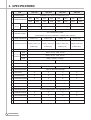
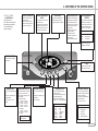
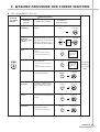
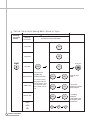
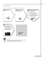
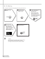
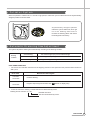
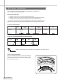
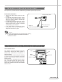
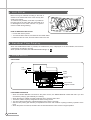
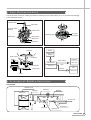
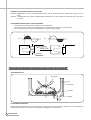
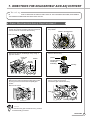
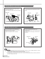
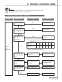
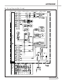
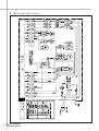
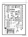
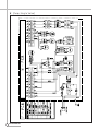
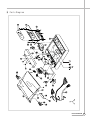
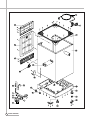
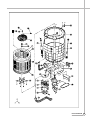
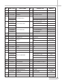
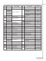
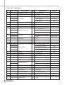
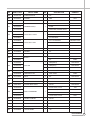
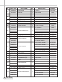
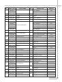
AUTO WASHER
WASHER
AUTO WASHER
AUTO WASHER
WASHER
AUTO WASHER
AUTO WASHER
AUTO WASHER
AUTO WASHER
AUTO WASHER
AUTO WASHER
AUTO WASHER
2
2. STRUCTURE OF THE WASHING MACHINE
3
3. FUNCTIONS OF THE CONTROL PANEL
4
4. DIRECTIONS FOR INSTALLATION AND USE
5
5
6
5. WASHING PROCEDURE AND COURSE SELECTION
FULL AUTOMATIC COURSE
PARTIAL SELECTIONS AMONG WASH, RINSE OR SPIN
DRY, SILK WAHING
ENCHANCED CONVENIENCE IN USE
7
8
9, 10
11
6. FEATURE AND TECHNICAL EXPLANATION
FEATURE OF THE WASHING MACHINE
WATER CURRENT TO ADJUST THE UNBALANCED LOAD
FUNCTION FOR SOAK WASH
AUTOMATIC WATER SUPPLY SYSTEM FOR BLANKET WASH
PULSATOR SYSTEM
AUTOMATIC DRAINING TIME ADJUSTMENT
SOFTENER DISPENSER
AUTOMATIC UNBALANCE ADJUSTMENT
CIRCULATING-WATER COURSE AND LINT FILTER
LINT FILTER
RESIDUAL TIME DISPLAY
DRAIN MOTOR
GEAR MECHANISM ASS’Y
PRINCIPLE OF BUBBLE GENERATOR
FUNCTIONAL PRINCIPLE OF BUBBLE WASHING MACHINE
12
12
12
12
13
13
14
15
15
16
16
16
17
17
18
7. DIRECTIONS FOR DISASSEMBLY AND ADJUSTMENT
GEAR MECHANISM ASS’Y REPLACEMENT
DRAIN MOTOR AND VALVE
BRAKE ADJUSTMENT
19
20
20
8. TROUBLE SHOOTING GUIDE
CONCERNING WATER SUPPLY
CONCERNING WASHING
CONCERNING DRAINING
CONCERNING SPINNING
CONCERNING OPERATION
9. PRESENTATION OF THE P.C.B ASS’Y
21
22
23
24
25
26
APPENDIX
WIRING DIAGRAM
PARTS DIAGRAM
PARTS LIST
CIRCUIT DIAGRAM
AUTO
AUTO WASHER
1. SPECIFICATIONS
INSTALLATION OF THE UNDER BASE COVER
HOW TO INSTALL ON AN INCLINED PLACE
HOW TO CONNECT THE INLET HOSE
AUTO
AUTO WASHER
AUTO WASHER
Contents
WASHING MACHINE
WASHER
AUTO
AUTO WASHER
AUTO WASHER
AUTO WASHER
AUTO WASHER
AUTO
AUTO WASHER
AUTO WASHER
AUTO WASHER
AUTO WASHER
AUTO WASHER
AUTO WASHER
AUTO WASHER
AUTO WASHER
AUTO WASHER
AUTO WASHER
AUTO WASHER
AUTO WASHER
AUTO WASHER
AUTO WASHER
AUTO WASHER
AUTO WASHER
AUTO WASHER
AUTO WASHER
AUTO WASHER
AUTO WASHER
AUTO WASHER
AUTO WASHER
AUTO WASHER
AUTO WASHER
AUTO WASHER
AUTO WASHER
AUTO WASHER
AUTO WASHER
AUTO WASHER
AUTO WASHER
AUTO WASHER
AUTO WASHER
AUTO WASHER
AUTO WASHER
AUTO WASHER
AUTO WASHER
AUTO WASHER
AUTO WASHER
AUTO WASHER
AUTO WASHER
AUTO WASHER
AUTO WASHER
AUTO WASHER
AUTO WASHER
AUTO WASHER
AUTO WASHER
WASHER
AUTO WASHER
27
31
34
42
1. SPECIFICATIONS
NO.
ITEM
DWF-1089
1
POWER SOURCE
2
POWER CONSUMPTION
DWF-9289
DWF-8089
DWF-7589
AVAILABLE IN ALL LOCAL AC VOLTAGE AND CYCLE
50Hz
60Hz
50Hz
60Hz
50Hz
60Hz
50Hz
60Hz
430W
480W
430W
480W
400W
460W
400W
460W
MACHINE NON-PUMP
55Kg (GROSS : 64Kg)
54Kg (GROSS : 63Kg)
50Kg (GROSS : 60Kg)
49Kg (GROSS : 59Kg)
WEIGHT
56Kg (GROSS : 65Kg)
55Kg (GROSS : 64Kg)
51Kg (GROSS : 61Kg)
50Kg (GROSS : 60Kg)
3
PUMP
4
DIMENSION (WXHXD)
5
WASHING COURSE
628 X 1005 X 673mm
610 X 962 X 655mm
FULL AUTOMATIC 8 COURSE
(FUZZY, MEMORY, DRY, SILK, ECONOMICAL, STRONG, NIGHT, BLANKET)
6
7
WATER CONSUMPTION
NORMAL 315L
NORMAL 304L
NORMAL 265L
NORMAL 259L
HIGH(96L), MID(81L)
HIGH(93L), MID(78L)
HIGH(82L), MID(70L)
HIGH(80L), MID(68L)
LOW(61L), SMALL(48L)
LOW(57L), SMALL(43L)
LOW(55L), SMALL(42L)
E.SMALL(33L)
E.SMALL(31.5L)
E.SMALL(30.5L)
WATER LEVEL SELECTOR LOW(65L), SMALL(49L)
E.SMALL(36L)
8
9
2
0.3kgf/cm2~8kgf/cm2 (2.94 N/cm2~78.4N/cm2)
OPERATING WATER PRESSURE
REVOLUTION
PER MINUTE
60Hz
WASH : 145~160, SPIN : 750~800
50Hz
WASH : 130~145, SPIN : 700~750
SILK, DRY
COURSE
WASH : 70 (60Hz), 60 (50Hz)
10
PULSATOR
11
WATER LAVEL CONTROL
12
ANTI NOISE PLATE
13
GEAR MECHANISM ASS’Y
14
LINT FILTER
O
O
O
O
15
SOFTENER INLET
O
O
O
O
16
FUNCTION FOR SOAK WASH
O
O
O
O
17
ALARM SIGNAL
O
O
O
O
18
RESIDUAL TIME DISPLAY
O
O
O
O
19
AUTO. WATER SUPPLY
O
O
O
O
20
NEW WATER FLOW
21
ECONOMIC COURSE
O
O
O
O
22
FUNCTION FOR BUBBLE
O
O
O
O
23
AUTO RE-FEED WATER
O
O
O
O
24
AUTO POWER OFF
O
O
O
O
SPECIFICATIONS
6 WINGS (Ø396mm)
6 WINGS (Ø376mm)
ELECTRONICAL SENSOR
O
O
O
O
HELICAL GEAR FOR LOW NOISE
WATER FLOW FOR ADJUST THE UNBALANCED LOAD
2. STRUCTURE OF THE WASHING MACHINE
•HOT WATER TAP
•COLD WATER TAP
After using the washer, course the water tap and
turn off the power
After using the washer,
close the water tap
and turn off the power.
•SOFTENER INLET
Pour softener into the softener inlet just before
wash and will be added into the tub automatically
just before the final rinse.
•TUB
•BLEACH INLET
•POWER SWITCH
•HOOK HOLE
•CONTROL PANEL
•LINT FILTER
•PULSATOR
•COVER UNDER
•POWER CORD
•GROUND WIRE
•ADJUSTABLE LEGS
In case of 3-wire
power cord ground
wire will not be
provided
•HOSE DRAIN
Accessories
DRYTEN
COVER UNDER [OPTION]
WATER TAP ADAPTER
INLET HOSE
HOSE DRAIN
HOSE DRAIN CLAMP
STRUCTURE
3
3. FUNCTIONS OF THE CONTROL PANEL
Control Panel
It has micom sensor.
As the buttons are pressed, the
lamps indicating the selection
of you desired washing
program will light up.
HOW TO USE SWITCH
BUTTON FOR PROGRAM
CANCEL
• Press this Switch to turn the
power ON or OFF .
After turning OFF the power,
wait for more than 3 seconds
and then turn it ON again.
• It can be used to cancel the fullautomatic course.
• When the button is pressed the
display will be light down. If you
want to wash, rinse or spin, you
can press one of the button.
TIME DISPLAY
START/HOLD BUTTON
• The lamps easily indicate the
option selection of washing
program and process by letters.
• Operation and temporary stop
are repeated as it is pressed it
will be repeated¡‚Operation¡„
,
¡‚Temporary stop¡„according to
the one time pressing or two
times pressing.
When you want to change
course in operating;
- Press the S/H button.
- Select the course that you
want to change.
- Press the S/H button again!
WASH TEMPERATURE
SELECTOR
• It can be used to choose water
temperature to be supplied.
• As the button is pressed, it will
be repeated following sings ;
COLD ¤A HOT ¤A WARM
TEMP.
: TEMPERATURE
WARM
COLD
HOT
: COLD+HOT WATER
: COLD WATER
: HOT WATER
• In case of the single valve
model, there is no water
PRE-ENGAGEMENT
ALL AUTOMATIC WASHER
AERO FUZZY & AIR POWER
• It can be used to pre-engage
time for wash
SOAK
18
RES.
RES. TIME
WARM
HOUR
MIN.
14
12
COLD
HOT
H.
M.
L.
S.
E.S
5
WASH
10
FUZZY MEM. DRY
6
4 SILK ECO. STRO. NIGHT BLAN 1
4
3
2
RINSE
1
SPIN
FEED
3
5
WASH TEMP.
FEED
9
WATER LEVEL
POWER
WASHING TIME
• It can be used to adjust washing
time
• As the button is pressed, you’ll
see the repeated.
4¤A6¤A10¤A12¤A14¤A18¤A
SOAK.
CANCEL
RINSE TIME SELECTOR
SPIN TIME SELECTOR
• This button selects the number
or times you want to rinse.
• As the button is pressed, it will
be repeated
• It can be used to change spin
time.
* Non-pump Model
¤A 1 time rinse ¤A 1 times feed
¤A 2 time rinse ¤A 2 times feed
¤A 3 time rinse ¤A 3 times feed
¤A 4 time rinse ¤A 4 times feed
¤A 5 time rinse ¤A 5 times feed
* Pump Model
¤A 1 time rinse ¤A 2 times rinse
¤A 3 times rinse ¤A 4 times rinse
¤A 5 times rinse
Rinse : Normal Rinse
Feed : Feed Rinse
• As the button is pressed, it will
be repeated
1¤A3¤A5¤A9 signs.
WASH
RINSE
SPIN
COURSE
• In case of the pump model,
there is no FEED function.
START/
HOLD
COURSE SELECTOR
WATER LEVEL SELECTOR
• It can be used to select the fullautomatic course.
• As the button is pressed, it will be
selected following order:
MEM.¤ADRY¤ASILK¤AECO.¤A
STRO.¤AN I G H T¤ABLAN¤AFUZZY
• It can be used to adjust amount
of water according to the size of
the load to be washed.
• As the button is pressed. Water
level is selected by
H.¤AM.¤AL.¤AS.¤AE.S
COURSE
MEM
DRY
SILK
ECO.
STRO.
NIGHT
BLAN
FUZZY
LEVEL. : WATER LEVEL
:
:
:
:
:
:
:
:
MEMORY
DRY
SILK
ECONOMICAL
STRONG
NIGHT
BLANKET
FUZZY
H.
M.
L.
S.
E.S.
: HIGH LEVEL
: MIDDLE LEVEL
: LOW LEVEL
: SMALL LEVEL
: EXTRA SMALL LEVEL
CONTROL PANEL
1
5. WASHING PROCEDURE AND COURSE SELECTION
§ è Full Automatic Course
¤Á Pressing
the Power
Switch
¤Ł Selecting Course
Selecting
Course
Kinds of the Laundry
FUZZY
(SENSOR)
This selection is for general
MEMORY
(USE ONLY FUZZY
COURSE)
This selection is washing course by
washing.
This selection is effective for some
clothes made of silk.
• Do not put in the wash marked with drycleaning.
• 1Kg’s lb’s limitation for one-time-wash.
ECONOMICAL
COURSE
START/HOLD
START/HOLD
Select
your
desired
items.
This selection is effective for delicate
• Just follow the washing procedure.
• 1.5Kg’s limitation for one-time-wash.
SILK
MEMORY
washing time, rinsing times, spin
clothese
POWER
FUZZY
your desire. (The memory items are
time, water level, water temperature)
DRY
Procedure to
Press the Button
This selection is effective for water
saving and energy saving.
DRY
COURSE
SILK
COURSE
ECONOMICAL
Pull the exclusive
detergent. Dry-10.
of 26g into the tub
for dilution with
water.
Pull the exclusive
detergent. Dry-10.
of 26g into the tub
for dilution with
water.
The washing
processed by
your desired
items.
START/HOLD
COURSE
STRONG
NIGHT
The selection is effective for bluejean, climbing clothes, ruck-sack,
sports wear(heavy dirty clothes),
etc.
This selection is for a night-washing
housewife who has no opportunity at
day time.
STRONG
START/HOLD
COURSE
NIGHT
START/HOLD
COURSE
BLANKET
This selection is effective for
blanket, curtain, carpet, etc...
•4 kg’s limitation for one-time-wash.
BLANKET
START/HOLD
COURSE
PROCEDURE
7
§ è Partial Selections Among Wash, Rinse, or Spin
¤Á Pressing
the Power
Switch
¤ Ł Selecting Course
Washing
Procedure
Procedure to Press the Button
Only Wash
WASH
Only Rinse
RINSE
POWER
START/HOLD
Only Spin
Wash & Rinse
Wash & spin
Rinse & Spin
Wash
¤x
Rinse
¤x
Spin
8
PARTIAL SELECTION
CANCEL
Cancel the set
program with
pressing the button.
*In case of canceling
the program while the
washer operates, press
the “Start/Hold” button
first, and then “Cancel”
one.
SPIN
RINSE
Press the “S/H”
button.
WASH
SPIN
If once more
pressed, the washer
will be stopped.
RINSE
SPIN
WASH
WASH
RINSE
SPIN
For keeping
Operation
continuously to the
set program, press
another time.
§ è Dry Washing
This selection is effective for high-quality sweater, underwear, wool, etc
1
Press the power
switch
2
Press the course
selection button to
adjust to “Dry”
3
Put the special detergent into
the tub, and press the
Start/Hold button
*After the height of water
reachs the small level of
water, the pulsator turns to
solve detergent, and the water
is continually supplied up to
the mid level of water.
POWER
4
START/
HOLD
COURSE
When the water
level reachs the mid
level, The buzzer
sounds, Now put the
clothes into the washing
machine. The LED
display lamp illuminates
as shown bellow.
START/
HOLD
NOTES
• Appropriate volume of washes are two to three suits of clothes.
• Only cold water should be supplied for washing.
• The height of water is fixed to the mid level of water.
DRY WASHING
9
§ è Silk Washing
This selection is effective for High-quality silk, stocking, silk curtain, etc
1
Press the power
switch
2
Press the course
selection button to
adjust to “SILK”
3
Put the special detergent into
the tub, and press the
Start/Hold button
*After the height of water
reachs the small level of
water, the pulsator turns to
solve detergent, and the water
is continually supplied up to
the mid level of water.
POWER
COURSE
START/
HOLD
4
When the water
level reachs the mid
level, The buzzer
sounds, Now put the
clothes into the washing
machine. The LED
display lamp illuminates
as shown bellow.
5
Shut the door and press the
Start/Hold button.
START/
HOLD
NOTES
• Appropriate volume of washes are five suits of clothes.
• Only cold water should be supplied for washing.
• The height of water is fixed to the mid level of water.
10
SILK WASHING
6. FEATURE AND TECHNICAL EXPLANATION
Feature of the Washing Machine
1
2
3
4
5
6
The first air bubble washing system in the world.
Quiet washing through the innovational low-noise design.
The wash effectiveness is much more enhanced because of the air bubble washing system.
The laundry detergent dissolves well in water because of the air bubble washing system.
The adoption of the water currents to adjust the unbalanced load.
One-touch operation system.
Water Current to Adjust the Unbalanced Load
It is a function to prevent eccentricity of the clothes after wash by rotating pulsator C.W and C.C.W for 20
seconds.(But, the DRY & SILK course have no operation of the water currents to adjust the unbalnced load.)
EFFECT
It reduces vibration and noise effectively while spinning.
WATER FLOW
WASH
DRAIN
SPIN
MOTOR
C.W
SINGAL
C.C.W
TIME(SEC.)
FILL
0.3
RINSE 1
0.5
DRAIN
0.3
0.5
SPIN
0.3
FILL
RINSE 2
0.5
•••••••
DRAIN
•••
20 SEC. (About 13 Times)
Function for Soak Wash
DISPLAY THE RESIDUAL TIME
When the SOAK WASH is selected, the total wash time increases because 30 minutes for soak process are added
to the time of main process.
PROGRESS
SOAK PROCESS
MAIN PROCESS
FILL
WASH
STOP
WASH
STOP
WASH
STOP
•
2’
8’
2’
8’
2’
8’
30 Minute
NOTES
‘ ’ mark indicates the operation of the water currents to adjust the unbalanced load.
Automatic Water Supply System For Blanket Wash
The water level would be lowered because the blanket absorbs water at the beginning of washing. Therefore, after
30 seconds, the operation is interrupted to check the water level, and then the water is supplied again until the
selected water level is reached.
12
EXPLANATION
Pulsator System
When the pulsator is rotated C.W or C.C.W at a high speed, it makes the cyclone water flow from the asymmetrically
designed pulsator as shown below.
Asymmetrically designed pulsator
makes the cyclone water fow, which get
rid of the washing dead zone to
increase the washing effect and reduce
the entanglement of laundry.
Automatic Drainning time Adjustment
This system adjusts the draining time automatically according to the draining condition.
Good draining
The washer begins spin process after drainage.
Bad draining
Draininig time is prolonged.
No draining
Program is stopped and gives the alarm.
Draining
condition
FUNCTIONAL PRINCIPLE
1
The micom can remember the time from the begining of drain to reset point when the pressure switch reaches to
“OFF” point
Drain Time
Movement of the Program
Less than
Continue draining
10 minutes
More than
Program stops and gives the alarm with
blinked on display lamp.
10 minutes
2
In case of continuous draining, residual drain time is determined by micom.
Draining time as a whole = D + 60
Residual drain time.
The time remembered by micom.
EXPLANATION
13
Softener Dispenser
This is the device to dispense the softener automatically by centrifugal force.
This is installed inside the auto-balancer.
FUNCTIONAL PRINCIPLE
1
2
3
4
Softener stays in room (A) when poured into softener inlet.
Softener moves from (A) to (B) by centrifugal force during intermittent spin process.
Softener flows from (B) to (C) during rinse process next to intermittent spin.
Softener moves from (C) to (D) by centrigfugal force during second intermittent spin.
After spin process is finished, the softener is added into the tub through softener outlet.
FLOW OF THE SOFTENER
Wash
Normal
Course
Intermittent
Spin
Centrifugal
force
(A)
Hold
Intermittent
Spin
Rinse
Flow in
Centrifugal
force
Flow in
(B)
(C)
Spin
(D)
FLOW OF THE SOFTENER INSIDE OF THE BALANCER
Room inside
the balancer
A
B
C
D
Centrifugal force
Flowing by weight
NOTES
Softener moves into the next room when r.p.m of the tub is more than 100 r.p.m.
HOW TO CHECK MOVEMENT
Pour a reasonable amount of “MILK” into softener
dispenser and operate the washer with no load. In final
rinse cycle, make sure that the milk is added into the
tub through softener outler.
Balancer
Softener
outlet
B
A
Softener inlet
14
EXPLANATION
D
C
Automatic Unbalance Adjustment
This system is to prevent abnormal vibration during intermittent spin and spin process.
FUNCTIONAL PRINCIPLE
Always the safety switch contact is “ON”
position.
2 In case that wash loads get uneven during
spin, the outer tub hits the safety switch
due to the serious vibration, and the spin
process is interrupted.
3 In case that P.C.B. ASS’Y gets “OFF” signal
from the safety switch, spin process are
stopped and rinse process is started
automatically by P.C.B. ASS’Y.
4 If the safety switch is operated due to the
unbalance of the tub, the program is
stopped and the alarm is given.
Contact of safety switch
1
Contact lever A
Position of
unbalanced load (OFF)
Normal (ON)
NOTES
The alarm finished when you close the lid after opening
it. Check the unbalance of the wash load and the
installation condition.
Circulating-Water Course and Lint Filter
CIRCULATING-WATER
The washing and rinsing effects have been
improved by adopting the water system in
which water in the tub is circulated in a
designed pattern.
When the pulsator rotates during the washing
or rinsing process, the water below the
pulsator vanes creates a water currents as
shown in figure.
The water is then discharged from the upper
part of the tub through the water channel.
About 40 L/min. water is circulated at the ‘high’
water level, standard wash load and standard
water currents.
Filter
Tub
Water
channel
Outer tub
Pulsator
EXPLANATION
15
Lint Filter
Much lint may be obtained according to the kind of
clothes to be washed and some of the lint may also
sticks to the clothes.
To minimize this possibility a lint filter is provided on
the upper part of the tub to filter the wash water as it
is discharged from the water channel. It is good to
use the lint filter during washing.
Filter
Filter
Bleach
Bleach
Inlet
Inlet
Pulsator
Pulsator
HOW TO REPLACE LINT FILTER
1 Pull the filter frame upward.
2 Turn the lint filter inside out, and wash the lint off with water.
3 Return the filter as it was, and fix the filter frame to the slot.
Residual Time Display
When the START/HOLD button is pressed, the residual time (min.) is displayed on the time indicator, and it will be
counted down according to process.
When operation is finished, the TIME INDICATOR will light up
.
Drain Motor
STRUCTURE
Pull
Loosen
Pulley
Lever
Inductive ring
Magnet
Coil of motor
Magnet of motor
FUNCTIONAL PRINCIPLE
1 When the DRAIN MOTOR connected to the power source, the DRAIN MOTOR rotates with 900 r.p.m and
revolves the pulley by gear assembly for reducing.
2 When the pulley is rotated, the pulley winds the wire to open the drain valve.
3 Therefore, rotation of pulley changed to the linear moving of wire.
4 The wire pulls the brake lever of Gear Mechanism Ass’y within 5 seconds.
5 After the wire pulled, gear assembly is separated from motor and condition of pulling is held by operation of the
lever.
6 When the power is turned off, the drain valve is closed because the wire returns to original position.
16
EXPLANATION
Gear Mechanism Ass’y
The proper water currents is made by the rotation of pulsator at a low speed (about 140 r.p.m) to prevent the damage
to the small sized clothes.
Pulsator shaft
Spin shaft
One way clutch
bearing
Gear unit as
Sun gear
Internal gear
Planetary gear
Clutch spring
Brake lever
Clutch boss
Gear pulley
Motor
Pulsator
1490 r.p.m
(50Hz)
Gear unit as
1 revolution
Motor
Pulsator
Gear Unit as
Gear Pulley
140 r.p.m
1/5.2
5.2 revolutions
750 r.p.m
Directly
Gear pulley
Tub
750 r.p.m
V-belt
Principle of Bubble Generator
STRUCTURE
Bobbin & coil
Armature
Magnet
Bellows
Trans core
Air
Air
Air out hole
Protector A
Air in hole
Protector B
EXPLANATION
17
PRINCIPLE OF INTAKE & OUTLET OF THE AIR
INTAKE : ARMATURE moves up, and BELLOWS inhales the air. At the same time, protector B is open and A is
close.
OUTLET : ARMATURE moves down, and BELLOWS exhausts the air. At the same time, protector B is close and A
is opend.
FUNCTIONAL PRINCIPLE OF TRANS & MAGNET
¡ The phase of A.C electric power changes to 60 cycle/second.
¡ The magnetic pole of trans core is changed by the change of the phase of A.C electric power.
¡ The core repeats push and pull (3600 times/min.) of the at mature magnet.
A.C
A.C
N
S
LEAF SPRING
NS
TRANS CORE
NS
S
N
MAGNET
Functional Principle of Bubble Washing Machine
ACROSS SECTION
Air bubble
Tub
Outer tub
Pulsator
Nozzle
FUNCTIONAL PRINCIPLE
Bubble generator supplies the air from the bottom of outer tub to the inner space of pulsator, the air is dispersed by
the rotation of pulsator. Air-bubble is created by the centrifugal force, and rises up.
18
EXPLANATION
7. DIRECTIONS FOR DISASSEMBLY AND ADJUSTMENT
Warning
BEFORE ATTEMPTING TO SERVICE OR ADJUST ANY PART OF THE WASHING MACHINE, DISCONNECT
THE POWER CORD FROM THE ELECTRIC OUTLET.
Gear Mechanism Ass’y Replacement
¡ Raise the top plate on the outer cabinet.
¡ Loosen four screws mounting outer tub cover and
¡ Loosen the pulsator mounting screw and remove
the pulsator.
remove outer tub cover from the tub ass’y.
Pulsator Mounting screw
Outer tub cover
¡ Remove the spinner shaft flange nut by using ‘T’
¡ Remove the tub ass’y.
type box wrench.
"T" type box
wrench
Washer
Nut-spin
shaft fixing
pulsator
Nut-spin shaft fixing
Washer-spin
Shaft fixing
Tub ass'y
¡ Lay the front of the washer on the floor.
¡ Remove four bolts mounting the plate-gear protect
¡ Remove four bolts mounting the gear mechanism
by using a box wrench and remove plate-gear
protect.
¡ Remove the V-belt.
¡ Pull out the gear mechanism ass’y.
ass’y by using a box wrench.
Gear mechanism
ass'y
Mounting bolt
Mounting bolt
NOTES
To assemble the gear mechanism ass’y, reverse
the disassembly procedure.
DIRECTIONS
19
Drain Motor and Valve
¡ Lay the front of the washer on the floor.
¡ Loosen the adjustment screw and four bolts
mounting the drain motor.
¡ Take out the wire of drain motor from the bracket.
Drain motor
¡ Separate the drain motor from the bracket.
¡ Turn the valve lid by using screw driver as shown
in figure and remove the valve lid from the valve
frame.
Valve frame
Bracket
Wire Bracket
Adjustment
screw
Adjustment
screw
Screw dirver
Valve lid Pin Bellows
Valve lid
Brake Adjustment
¡ Loosen the adjustment screw fastening the
bracket and place the adjustment screw to the
brake lever as shown in figure.
¡ Tighten the adjustment screw completely.
3mm
¡ Loosen the adjustment bolt and turn the
adjustment bolt until the end of the bolt touches to
the brake lever.
¡ Tighten the lock nut and apply a small amount of
paint-lock.
Adjustment bolt
Brake lever
Gear mechanism ass'y
Brake lever
Adjustment screw
Clutch lever
NOTES
1. The brake adjustment has been made at the factory, so that it is not to re-adjust. However, in case of
insufficient brake operation, perform the upper procedure.
2. Overtightening of the adjustment bolt will cause poor brake performance.
3. Undertightening of the adjustment bolt will cause continuous bracking and, thereby, cause the problems of
the motor during the spin cycle.
20
DIRECTION
8. TROUBLE SHOOTING GUIDE
NOTES
1. When replace the P.C.B. ASS’Y do not scratch the surface of the P.C.B. ASS’Y.
2. Disconnect the power cord from the electric outlet.
Concerning Water Supply
PROBLEM
CHECK POINT
CAUSE
Do you open the water
tap?
NO
SOLUTION
Open the water tap.
YES
YES
Is the filter of the water
inlet valve clogged with
dirt?
Clean the filter.
NO
WATER IS
NOT
SUPPLIED.
Increase the water
pressure.
NO
Is the water pressure
sufficient?
(0.3~8 kgf/cm2)
NOTE : Open the water tap fully and measure
the flow rate.
Flow
rate(l/min.)
Water pressure
(Kgf/cm2)
YES
11.5
15.0
18.0
20.3
24.1
27.4
0.3
0.4
0.5
0.6
0.8
1.0
From the upper results, you know that the flow rate more than
11.5l/min. is essential for water supply.
Does the water inlet
valve make operating
sound?
NO
Water inlet valve
is defective.
Change water inlet valve.
Improper connection of
the connector or the
terminal.
Connect the connector or
the terminal properly.
P.C.B AS is defective.
Change the P.C.B AS.
Lead wire is defective.
Change the lead wires.
YES
Is the connector or the
terminal connected
properly?
NO
YES
Is the output voltage of
the P.C.B normal?
NO
YES
TROUBLE SHOOTING
21
PROBLEM
CHECK POINT
Does the water supply
continue while the power
is turned off?
CAUSE
SOLUTION
YES
The water inlet valve is
defective.
Change the water inlet
valve.
YES
The triac of P.C.B is
defective.
Change the P.C.B ASS’Y.
NO
Does the water supply start
as soon as you press the
power switch?
NO
WATER
SUPPLY IS
NOT
STOPPED.
Operate the washer after
setting the water level to
“HIGH”
NO
Does the water supply
continue after the water
reaches to the “HIGH”
level?
YES
Is the air tube of water
level switch kinked or
deformed?
Normal operation.
YES
NO
Air tube is defective.
Change the air tube.
Pressure switch is
defective.
Change the pressure
switch.
Concerning Washing
PROBLEM
CHECK POINT
CAUSE
SOLUTION
Does the motor operate after
finishing water supply?
NO
YES
Does pulsator rotate in
only one direction?
YES The triac of P.C.B is
defective.
NO
THE
PULSATOR
DOES NOT
ROTATE EVEN
IF THE WATER
IS SUPPLED.
YES
NO
Is the motor coil
disconnected?
YES
Is the V-belt worn out?
NO
TROUBLE SHOOTING
Normal
Does the motor make
operating sound?
Is the connection
condition of capacitor
terminal good?
22
Change the P.C.B
ASS’Y.
YES
NO
Motor is defective.
Improper connection
NO
V-belt is defective.
Change the motor.
Connect the terminal
properly.
Change the V-belt.
Change the motor.
Concerning Draining
PROBLEM
CHECK POINT
Do you install the
drain hose
properly?
CAUSE
NO
SOLUTION
Improper installation
Install the drain hose
properly.
Malfunction of drainage
by the foreign matter
Remove the foreign
matter from the pump
housing
Drain pump is defective
Change the Drain pump
P.C.B ASS’Y is defective.
Change the P.C.B ASS’Y.
YES
THE WASHER
DOES NOT
DRAIN.
Is the foreign matter
accumulated inside
the pump housig?
YES
NO
Is the output voltage of
the drain pump
normal?
YES
NO
TROUBLE SHOOTING
23
Concerning Spinning
PROBLEM
CHECK POINT
CAUSE
SOLUTION
YES
Close the lid.
Is the lid open?
NO
Does the door switch
operate normally?
Does the safety switch
operate normally?
NO
Door switch is defective.
Change the door switch.
Safety switch is
defective.
Change the safety
switch.
Improper connection of
the connector.
Connect the connector
properly.
P.C.B. ASS’Y is
defective.
Change P.C.B ASS’Y.
Drain motor is defective.
Change the drain motor.
P.C.B ASS’Y is defective.
Change the P.C.B ASS’Y.
V-belt is defective.
Change the V-belt.
Motor is defective.
Change the motor.
Improper connection.
Connect the terminal
correctly.
P.C.B ASS’Y is defective.
Change the P.C.B ASS’Y.
YES
Is the connector of
P.C.B ASS‘Y connected
properly?
NO
YES
THE WASHER
DOES NOT
SPIN.
Does the pulsator rotate
while the tub does not
rotate?
NO
YES
Is the input
voltage of the drain
motor normal?
YES
NO
YES
Is the V-belt worn out?
NO
Is the input voltage of
motor normal?
YES
NO
Is the connection
condition of capacitor
terminal good?
NO
YES
24
TROUBLE SHOOTING
Concerning Operation
PROBLEM
CHECK POINT
CAUSE
SOLUTION
NO
Is the plug connect-ed
to electric outlet?
Connect the plug.
YES
YES
Is Fuse opended?
Change Fuse
NO
THE
INDICATOR
LAMPS(L.E.D)
DO NOT LIGHT
UP WHEN THE
POWER
BUTTON IS
PRESSED.
Is the condition of
power button good?
MOTOR
ROTATES
WHEN
START/HOLD
BUTTON IS
NOT
PRESSED.
ABNORMAL
NOISE
DURING WASH
PROCESS.
Power button is defective
Change P.C.B ASS’Y.
Improper connection of
the connector.
Connect the connector
properly.
Transformer is defective
Change the transformer.
P.C.B. ASS’Y is
defective.
Change P.C.B ASS’Y.
NO
Press START/HOLD
button.
YES
Is the connector of the
P.C.B. ASS’Y
connected properly?
NO
YES
Is input voltage of the
transformer normal?
PROGRESS
LAMPS(LED)
DO NOT LIGHT
UP.
NO
NO
Do you press
START/HOLD button?
YES
Does the pressure switch
operate normally?
NO
Replace P.C.B ASS’Y.
Pressure switch is
defective.
Change the pressure
switch.
Abnormal
YES
Check the output voltage
of P.C.B ASS’Y
Is the strange noise
generated when the
pulsator rotates in TEST
MODE of P.C.B ASS’Y?
P.C.B ASS’Y is defective.
YES
P.C.B ASS’Y is defective
Change P.C.B ASS’Y.
There is foreign matter
between pulsator and
tub.
Remove the foreign
matter.
V-belt is defective.
Change the V-belt.
NO
YES
Is the V-belt worn out?
TROUBLE SHOOTING
25
9. PRESENTATION OF THE P.C.B ASS’Y
Concerning Error Message
MESSAGE
CAUSE
Improper installation of drain hose.
Install drain hose properly.
The drain hose is blocked up by foreign
matter.
Remove foreign matter from drain hose.
Drain motor is inferior.
Change drain motor.
The water tap is closed.
Open the water tap.
The water inlet filter clogged.
Clean the water inlet filter.
It passes over the 30 minutes, yet it doesn’t
come to assigned water level.
Check whether or not is comes to the
assigned water level.
Wash loads get uneven during spin.
Re-set wash loads evenly.
Poor installation of the unit.
Proper installation.
The lid is opened.
Close the lid.
The safety switch is inferior.
Change the safety switch.
The load sensing is inferior. After the load
sensing operates about 20 seconds, the
message is displayed during 0.5 second
and water level is always fixed ‘high’.
The water level sensing is inferior.
26
PCB ASS’Y
SOLUTION
Change the P.C.B. ASS’Y.
Check the water level sensor and the
contact part of the connector.
APPENDIX
§ è Wiring Diagram [Non-Pump]
WIRING DIAGRAM
27
§ è [Non-Pump, Single Valve]
28
WIRING DIAGRAM
§ è [Pump]
WIRING DIAGRAM
29
§ è [Pump, Single Valve]
30
WIRING DIAGRAM
§ è Parts Diagram
A10
PARTS DIAGRAM
31
B24
B23
B15
B16
B17
B18
B22
B19
B21
B20
32
PARTS DIAGRAM
C32
PARTS DIAGRAM
33
§ è Parts List
1. DWF-7589, DWF-8089
NO
PART CODE
PARTS NAME
EA
A01
3611611400
DECORATOR PANEL F
1
PC FILM 0.188T
A02
3614215900
PANEL F
1
ABS
PRPSSWN500
A03
PRPSSWN800
P.C.B ASS¡fl
Y
1
PRPSSWN900
NON-PUMP
DWF-1089CTE
NON-PUMP
A04
3614504200
PLATE T
1
ABS
A05
3610906700
CAP
2
ABS
A06
3616001200
SPECIAL BOLT
2
T1 TRS 5x73
A07
3610014351
PUMP
AC 110-130V/60Hz
BUBBLE PUMP ASS¡fl
Y
1
3610028701
AC 220-240V/50Hz
AC 220V/60Hz
A08
3614202000
PANEL B
1
ABS
A09
3610902600
CAP REAR
2
CR
A10
3611105400
CASE DETERGENT
1
ABS
A11
3612300110
GASKET VALVE
2
PVC-S
5EP1048010
1EA;SINGLE VALVE
T5-V1 (AC 110-130V)
5EP1048020
A12
REMARK
DWF-1089
DWF-1089PT
3618902101
T5-V1F(AC 110-130V)
TRANS POWER
FUSE
1
5EP1048030
T5-V2 (AC 220-240V)
5EP1048040
T5-V2F(AC 220-240V)
FUSE
RIGHT
A13
3615103500
SPRING
1
SUS 304 D=2.0
A14
3612900400
HINGE LEFT
1
POLYACETAL
A15
3612900300
HINGE RIGHT
1
POLYACETAL
A16
3615103600
SPRING
1
SUS 304 D=2.0
A17
3619007800
SWITCH DOOR AS
1
DWDS-01
BASE DETERGENT
1
3610400800
A18
PP
A19
3619006720
SWITCH SAFETY
1
DC 15V 10mA\
A20
3611404601
COVER R
1
ABS
A21
3610903000
CAP DOOR AS
2
80¡fl
S, 88¡fl
S
A22
3619005110
SWITCH PRESSURE
1
KANBAYASHI(PS-D7)
A23
3611715101
DOOR F
1
ABS
A24
3611715201
DOOR B
1
ABS
A25
3612602600
HANDLE DOOR
1
ABS
PARTS DIAGRAM
LEFT
PP
3610400820
34
DESCRIPTION
SINGLE VALVE
RIGHT
NO
PART CODE
PARTS NAME
EA
A26
3611521700
CUSHION DOOR
4
CR
A27
3611405101
COVER L
1
ABS
A28
7121401608
SCREW
8
T2S PAN 4x16 SUS
3612725100
A29
A30
A31
3612725110
DESCRIPTION
LEFT
NON-PUMP
HARNESS ASS¡fl
Y
1
PUMP
3612725120
NON-PUMP, SINGLE VALVE
3615403510
AC 110-130V/60Hz
3615403710
REMARK
VALVE INLET COLD
1
AC 220-240V/50Hz
3615402010
AC 220V/60Hz
3615403630
AC 110-130V/60Hz
0EA;SINGLE VALVE
AC 220-240V/50Hz
0EA;SINGLE VALVE
AC 220V/60Hz
0EA;SINGLE VALVE
3615403830
VALVE INLET HOT
1
3615402130
A32
7121301208
SCREW
2
T2S TRS 3x12 SUS
B01
3612200100
FRAME T
1
PP
B02
3610805600
CABINET AS
1
PAINTING
BASE U
1
3610303130
B03
3610303110
B04
-
B05
PP
NON-PUMP
PP
PUMP
-
-
-
3617702000
LEG ADJUST
2
PP
B06
3612100300
FOOT
2
PP
B07
4509D10020
FOOT
2
RUBBER BUTYL
B08
-
-
-
-
3610076130
54.0¥F+60¥H, L=470
110V
41.6¥F+60¥H, L=470
127V
3610032630
13.5¥F+60¥H, L=470
220V
3610031930
12.5¥F+60¥H, L=470
240V
3610076230
B09
ASSY CONDENSER
1
B10
3612600700
HANDLE CABINET
2
PE-HD
B11
3610068700
ASSY EARTH
1
50/0.18 GREEN ST710480-2
B12
-
-
-
-
B13
3611402800
COVER BACK
1
PP
B14
3614504300
PLATE UPPER
1
PP
3613214200
HOSE DRAIN O AS
1
L=1000
3613203101
HOSE AS
1
DWF-5230PN
PUMP
B16
3612502300
GUIDE DRAIN HOSE
1
PP
PUMP
B17
3611201000
CLAMP
1
HSW3,D2.6,MFZN,D36
NON-PUMP
B15
NON-PUMP
PARTS DIAGRAM
35
NO
PART CODE
3611200200
PARTS NAME
EA
CLAMP B
1
TERMINAL PUMP
1
3618703700
B18
3618703720
REMARK
SW D2.6 ZN8-C
PUMP
250V/1A
PUMP
125V/3.15A
PUMP
B19
3611405320
COVER PUMP
1
PP
PUMP
B20
7122501611
SCREW TAPPING
3
T2 TRS 5x16 MFZN
PUMP
AC 110V/60Hz
PUMP
AC 120V/60Hz
PUMP
3963322730
AC 220V/60Hz
PUMP
3963513430
AC 220-240V/50Hz
PUMP
DWF-5590DPNF, E-TYPE
PUMP
3963220330
3963821530
B21
B22
MOTOR SHADED POLE
3611901530
FILTER AS
1
1
3618912600
B23
B24
3618912630
AC 250V/4A, FERRITE
UNIT FUSE FILTER
1
AC 250V/5A, FERRITE
TUV
3618912610
AC 250V/8A, FERRITE
3611301300
3x0.75, 300x2, 300-RTML
ITALIAN 3PIN
4508B81001
3x0.75, 300x2, 300-RTML
CP-2PIN
3x0.75, 300x2, 300-RTML
3-WIRE
450E181000
POWER CORD AS
1
WAK42H762-
A VCTFK 2x0.75, 2.3M
450KA81003
3x0.75, 300x2, 300-RTML
C01
3618101400
NOZZLE BODY
1
PP
C02
3611408500
COVER TUB O
1
PP
C03
3619801100
SUSPENSION AS(A)
2
DWF-7581
C04
3619801200
SUSPENSION AS(B)
2
DWF-7581
TUB O
1
3618802620
C05
3618802630
FLAT 2PIN
EUROPE-2PIN
PP
NON-PUMP
PP
PUMP
C06
3613208900
HOSE OVERFLOW
1
PE-LD
NON-PUMP
C07
3615404000
VALVE DRAIN AS
1
DWF-5590D, VE
NON-PUMP
450ED45020
AC 110-130V/60Hz
NON-PUMP
3966320210
AC 220V/60Hz
NON-PUMP
AC 220-240V/50Hz
NON-PUMP
450ED45040
AC 110-130V/60Hz
PUMP
3966320240
AC 220V/60Hz
PUMP
3966010140
AC 220-240V/50Hz
PUMP
3966010120
C08
36
DESCRIPTION
MOTOR SYNCHRONOUS
1
C09
3610303000
BASE
1
SECEN 2.0Tx410x385
C10
4500D08180
CLAMP
1
SWC
C11
4500D08170
HOSE
0.62
PARTS DIAGRAM
ID=8.0, OD=12.0
NO
PART CODE
C12
3611502800
C13
C14
PARTS NAME
CUSHION DOWN
EA
2
DESCRIPTION
REMARK
POM H=18mm
3964220400
AC 110V/60Hz
F34-C
3964820510
AC 127V/60Hz
F36-C
AC 220/60Hz
F3A-C
3964310510
AC 220V/50Hz
F32-1C
3964610310
AC 240V/50Hz
F33-1C
3610019700
3611502000
MOTOR CONDENSER
1
CUSHION UPPER
2
PULLEY MOTOR AS
1
3618401400
C15
3618401420
POM
ADC-12, DS=10, DP=48.5
60Hz
ADC-12, DS=10, DP=53.0
50Hz
3613218500
HOSE DRAIN AS
1
PE-LD/EVA, L=219.5
3613212100
HOSE DRAIN I
1
PE-LD/EVA, L=184
C17
3617301000
GEAR MECHAISM
1
GM-6685D, NTN
C18
3618300100
PLATE GEAR PROTECTOR
1
SBHG 1.6T
C19
-
-
-
-
C20
4507D34020
BELT V
1
M20
C21
3610906200
CAP PULSATOR
1
PP
C22
4505E3203A
SC PULSATOR FIX AS
1
6x26.5 O-RING+SILOCK
C23
3610906400
CAP
1
PP
C24
3610085500
ASS¡fl
Y FILTER
1
PP(NYLON 74x130)
C25
3619702900
PULSATOR AS
1
PULSATOR+INSERT
C26
4509G83081
NUT-SPIN SHAFT
1
ZDC2 CU, NI COATING
C27
4509L83070
SPECIAL WASHER
1
SUS304 T2.0 PI44
BALANCER AS
1
NON-PUMP
C16
3610009900
C28
3616101600
3618800301
TUB INNER
C29
PUMP
50Hz, 60Hz
DWF-7590R
DWF-7589series
DWF-8080R2
DWF-8089series
PP
DWF-7589series
YUS 430D
DWF-8089series
DWF-8089series
1
3618801700
TUB
C30
3618802000
TUB U
1
PP
C31
3617200200
FLANGE TUB
1
ADC 12
3612500100
GUIDE FILTER
C32
PP
DWF-7589series
DWF-8080R2
DWF-8089series
1
3612502200
GUIDE FILTER AS
PARTS DIAGRAM
37
2. DWF-9289, DWF-1089
NO
PART CODE
PARTS NAME
EA
A01
3611611400
DECORATOR PANEL F
1
PC FILM 0.188T
A02
3614215300
PANEL F
1
ABS
PRPSSWN500
A03
PRPSSWN800
P.C.B ASS¡fl
Y
1
PRPSSWN900
NON-PUMP
DWF-1089CTE
NON-PUMP
A04
3614502100
PLATE T
1
ABS
A05
3610906700
CAP
2
ABS
A06
3616001200
SPECIAL BOLT
2
T1 TRS 5x73
A07
3610014711
BUBBLE PUMP ASS¡fl
Y
1
AC 220-240V/50Hz
AC 220V/60Hz
3614201000
ABS
PANEL B
1
3614201540
ABS
A09
3610902600
CAP REAR
2
CR
A10
3611105400
CASE DETERGENT
1
ABS
A11
3612300110
GASKET VALVE
2
PVC-S
5EP1048010
SINGLE VALVE
1EA;SINGLE VALVE
T5-V1 (AC 110-130V)
5EP1048020
A12
PUMP
AC 110-130V/60Hz
3610031401
A08
REMARK
DWF-1089
DWF-1089PT
3610031411
T5-V1F(AC 110-130V)
TRANS POWER
FUSE
1
5EP1048030
T5-V2 (AC 220-240V)
5EP1048040
T5-V2F(AC 220-240V)
FUSE
RIGHT
A13
3615103500
SPRING
1
SUS 304 D=2.0
A14
3612900400
HINGE LEFT
1
POLYACETAL
A15
3612900300
HINGE RIGHT
1
POLYACETAL
A16
3615103600
SPRING
1
SUS 304 D=2.0
A17
3619007800
SWITCH DOOR AS
1
DWDS-01
BASE DETERGENT
1
3610400800
A18
PP
A19
3619006710
SWITCH SAFETY
1
DC 15V 10mA
A20
3611405910
COVER R
1
ABS
A21
3610903000
CAP DOOR AS
2
80¡fl
S, 88¡fl
S
A22
3619005110
SWITCH PRESSURE
1
KANBAYASHI(PS-D7)
A23
3611716800
DOOR F
1
ABS
A24
3611716900
DOOR B
1
ABS
A25
3612602600
HANDLE DOOR
1
ABS
PARTS DIAGRAM
LEFT
PP
3610400820
38
DESCRIPTION
SINGLE VALVE
RIGHT
NO
PART CODE
PARTS NAME
EA
A26
3611521700
CUSHION DOOR
4
CR
A27
3611406010
COVER L
1
ABS
A28
7121401608
SCREW
8
T2S PAN 4x16 SUS
3612725100
A29
A30
A31
3612725110
DESCRIPTION
HARNESS ASS¡fl
Y
1
PUMP
NON-PUMP, SINGLE VALVE
3615403510
AC 110-130V/60Hz
VALVE INLET COLD
1
AC 220-240V/50Hz
3615402010
AC 220V/60Hz
3615403630
AC 110-130V/60Hz
0EA;SINGLE VALVE
AC 220-240V/50Hz
0EA;SINGLE VALVE
AC 220V/60Hz
0EA;SINGLE VALVE
3615403830
VALVE INLET HOT
1
3615402130
A32
7121301208
SCREW
2
T2S TRS 3x12 SUS
B01
3612200200
FRAME T
1
PP
B02
3610806900
CABINET AS
1
PAINTING
BASE U
1
3610301000
B03
3610303610
3610901800
B04
LEFT
NON-PUMP
3612725120
3615403710
REMARK
3610901700
CAP LEG
3610904100
PP
NON-PUMP
PP
PUMP
1
ABS(RIGHT)
NON-PUMP
1
ABS(LEFT)
NON-PUMP
2
ABS
PUMP
3617702000
LEG ADJUST
2
PP
NON-PUMP
3610009100
LEG ADJUST AS
2
DWF-7590R
3612100300
FOOT
2
PP
NON-PUMP
4509D10020
FOOT
2
RUBBER BUTYL
NON-PUMP
610017400
ASS¡fl
Y LEG FIX
2
DWF-7590R
4509L03031
COVER DRAIN HOLE
1
PE-HD
B05
B06
PUMP
B07
B08
3610076130
PUMP
NON-PUMP
54.0¥F+60¥H, L=470
110V
41.6¥F+60¥H, L=470
127V
3610032630
13.5¥F+60¥H, L=470
220V
3610031930
12.5¥F+60¥H, L=470
240V
3610076230
B09
ASSY CONDENSER
1
B10
3612600700
HANDLE CABINET
2
PE-HD
B11
3610068700
ASSY EARTH
1
50/0.18 GREEN ST710480-2
B12
3614502000
PLATE LOWER
1
PP
B13
3611402800
COVER BACK
1
PP
B14
3614502200
PLATE UPPER
1
PP
PARTS DIAGRAM
39
NO
PART CODE
PARTS NAME
EA
DESCRIPTION
REMARK
4509M56000
HOSE DRAIN
1
L=930mm
NON-PUMP
3613203101
HOSE AS
1
DWF-5230PN
PUMP
3612502300
GUIDE DRAIN HOSE
1
PP
PUMP
4501F06120
CLAMP
1
SWPA2 ZN8-C
NON-PUMP
3611200200
CLAMP B
1
SW D2.6 ZN8-C
PUMP
3618703700
TERMINAL PUMP
1
250V/1A
PUMP
125V/3.15A
PUMP
B15
B16
B17
B18
618703720
B19
3611405320
COVER PUMP
1
PP
PUMP
B20
7122501611
SCREW TAPPING
3
T2 TRS 5x16 MFZN
PUMP
AC 110V/60Hz
PUMP
AC 120V/60Hz
PUMP
3963322730
AC 220V/60Hz
PUMP
3963513430
AC 220-240V/50Hz
PUMP
DWF-5590DPNF, E-TYPE
PUMP
3963220330
3963821530
B21
B22
MOTOR SHADED POLE
3611901530
FILTER AS
1
1
3618912600
B23
B24
3618912630
AC 250V/4A, FERRITE
UNIT FUSE FILTER
1
AC 250V/5A, FERRITE
TUV
3618912610
AC 250V/8A, FERRITE
3611301300
3x0.75, 300x2, 300-RTML
ITALIAN 3PIN
4508B81001
3x0.75, 300x2, 300-RTML
CP-2PIN
3x0.75, 300x2, 300-RTML
3-WIRE
450E181000
POWER CORD AS
1
WAK42H762-
A VCTFK 2x0.75, 2.3M
450KA81003
3x0.75, 300x2, 300-RTML
C01
3618101400
NOZZLE BODY
1
PP
C02
4509M83030
COVER TUB O
1
PP
C03
3610065800
SUSPENSION AS(A)
2
DWF-9290RD
C04
3610065900
SUSPENSION AS(B)
2
DWF-9290RD
C05
4509M83012
TUB O
1
PP
HOSE OVERFLOW
1
4509M06010
C06
3613205400
FLAT 2PIN
EUROPE-2PIN
PE-LD
NON-PUMP
FRPP
PUMP
4509K78000
VALVE DRAIN AS
1
NON-VE
3617100510
ELBOW DRAIN
1
PP
NON-PUMP
C07
450ED45030
AC 110-130V/60Hz
NON-PUMP
AC 220V/60Hz
NON-PUMP
3966010130
AC 220-240V/50Hz
NON-PUMP
450ED45040
AC 110-130V/60Hz
PUMP
3966320220
C08
40
PUMP
MOTOR SYNCHRONOUS
PARTS DIAGRAM
1
NO
PART CODE
PARTS NAME
EA
DESCRIPTION
3966320240
AC 220V/60Hz
PUMP
3966010140
AC 220-240V/50Hz
PUMP
C09
4509M34010
BASE
1
SECEN 2.0Tx410x385
C10
4500D08180
CLAMP
1
SWC
C11
4500D08170
HOSE
0.36
C12
3611502800
CUSHION DOWN
C13
C14
REMARK
2
ID=8.0, OD=12.0
POM H=18mm
3964220400
AC 110V/60Hz
F34-C
3964820510
AC 127V/60Hz
F36-C
AC 220/60Hz
F3A-C
3964310510
AC 220V/50Hz
F32-1C
3964610310
AC 240V/50Hz
F33-1C
3610019700
3611502000
MOTOR CONDENSER
1
CUSHION UPPER
2
PULLEY MOTOR AS
1
3618401400
C15
3618401420
POM
ADC-12, DS=10, DP=48.5
60Hz
ADC-12, DS=10, DP=53.0
50Hz
3613206700
HOSE DRAIN AS
1
PE-LD/EVA, L=452
NON-PUMP
3613212100
HOSE DRAIN I
1
PE-LD/EVA, L=184
PUMP
C17
3617304600
GEAR MECHAISM
1
GM-9289
C18
3618300100
PLATE GEAR PROTECTOR
1
SBHG 1.6T
C19
3616100600
BALANCER WEIGHT
1
FC-20, 3550Gr
BELT V
1
C16
4507D34020
C20
3616500500
M20
60Hz
M20.5
50Hz
C21
3610906200
CAP PULSATOR
1
PP
C22
4505E3203A
SC PULSATOR FIX AS
1
6x26.5 O-RING+SILOCK
C23
3610906400
CAP
1
PP
C24
3610085500
ASS¡fl
Y FILTER
1
PP(NYLON 74x130)
C25
3619702820
PULSATOR AS
1
PULSATOR+INSERT
C26
4509G83081
NUT-SPIN SHAFT
1
ZDC2 CU, NI COATING
C27
4509L83070
SPECIAL WASHER
1
SUS304 T2.0 PI44
BALANCER AS
1
4509M30000
C28
3616101500
4509M05010
TUB INNER
C29
DWF-8088T
DWF-9289series
DWF-1080R2
DWF-1089series
PP
DWF-9289series
YUS 430D
DWF-1089series
DWF-1089series
1
3618801600
TUB
C30
3618801900
TUB U
1
FRPP
C31
3617200200
FLANGE TUB
1
ADC 12
4509M05031
GUIDE FILTER
C32
PP
DWF-9289series
DWF-1080R2
DWF-1089series
1
3612501800
GUIDE FILTER AS
PARTS DIAGRAM
41