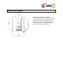
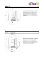
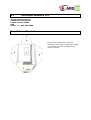
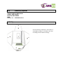
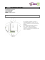
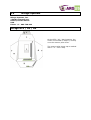
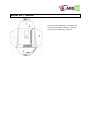
1
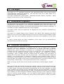
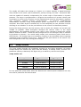
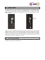
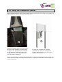
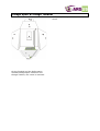
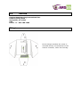
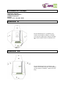
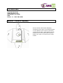
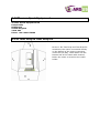
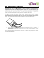
Preliminary
Argus installation guide
Index
1.0
The Argus
1.1
1.2
1.3
Installation in General
Technical Information
Jump Modes
2.0
Installation the Argus to your Container
2.1
2.2
2.3
2.3.1
2.4
Pouch for Processing Unit
Cutter Holder
Control Unit Holder
Using the transparent pocket
Cable placement
3.0
Installation into common Containers
3.1
Rigging Innovations Inc.
Talon 2
Talon FS & Voodoo
Talon FX
Talon 1 & Telesis 1
Aerodyne Research LLC
Icon & Icon Student
Velocity Sports
Infinity
Parachutes de France
Atom
Mirage Systems
Mirage RTS / G3 / G4
Relative Workshop / United Parachute Technologies
Vector II
Vector III / Micron
Paratec
Ultra II & Next
Performance Variable / Firebird
Performance Variable Tandem
Omega & Omega Tandem
Sunrise
Wings
Basik Air Concept
Advanced “in”
Advanced “out”
Sun Path
Javelin / Javelin Odyssey
Thomas Sport Equipment
1-Pin Tear Drop & Tear Drop FS
Jump Shack
Racer, Racer Elite
3.2
3.3
3.4
3.5
3.6
3.7
3.8
3.9
3.10
3.11
3.12
3.13
4.
Packing your Reserve/Container with Argus
4.1
4.2
Loop material
Argus Loops
4.3
4.4
Loop washer
Tools to use
5.
Maintenance for the Argus
5.1
5.2
5.3
5.4
Battery replacement
Water Resistant Filter replacement
Cutter Replacement
Software Update
6.
Argus Scheduled Service
6.1
6.2
6.3
6.4
6.5
6.6
ARGUS Scheduled Service
Battery replacement - sticker
Warranty period
ARGUS Service
Service Locations
Cost of Scheduled Service
7.
Warnings
1.0 The Argus
The Argus is a 3rd generation electronic and pyrotechnic safety device with superior
electromagnetic interference shielding. The unit also works as a data logger, as it
memorizes most jump parameters.
The Argus includes four jump modes – Standard, Tandem, Novice, & Swoop - which
support a wide variety of user requirements.
1.1 Installation in general
The Argus has been designed to be backward compatible with most sport rigs on the
market today. It will easily fit in any currently available AAD pouch which is located in the
bottom of the reserve container, on the wall separating the main & reserve containers. If
necessary, an Argus installation-setup kit can be supplied.
The Argus cutter must be positioned as specified by the container manufacturers’
instructions.
The Argus is a rugged safety device. However, be careful when handling the Argus
cables. Do not pull at the cables and take care with the remote control window. Please
comply with any country-specific regulations concerning the installation of the Argus
AAD.
In case of doubt about the exact installation of the Argus, the rig manufacturers’
instructions will override this manual.
1.2 Technical Information
The Argus works by measuring air pressure and the rate of change of air pressure,
together with other parameters. Air pressure is, of course, the basis of altitude
measurement. When the Argus is switched on, it calibrates itself to the ambient air
pressure and then memorizes this as its zero or ground level. It re-calibrates regularly,
to check for any pressure changes caused by weather, and updates its memory
accordingly. Thus, it always knows the latest actual air pressure and its memory is
always set to the most accurate zero or ground level. The microprocessor recognizes
takeoff in the aircraft when it registers a signature rapid pressure change. Then, it
changes to a fast calculation mode in which it evaluates a series of firing criteria at short
time intervals. All of these criteria must be positive before the unit will fire. Once the unit
passes 500m (1600ft) AGL, it arms itself and becomes fully operational.
NOTE: the Argus will not work if the aircraft is exited before reaching 500m (1600ft)
AGL.
Once the aircraft has climbed through this altitude, and the Argus has become fully
operational, it will work for any exit altitude. During a descent in the aircraft, in freefall,
or under canopy, the Argus will monitor all parameters, all the way to landing. In swoop
mode, however, this process is put on standby after an opening is detected. Advanced
technology and superior programming are used to eliminate the influence of air vortices.
Such vortices can cause erroneous altitude readings varying by more than 100 meters
(300 ft) from the actual altitude. You can observe these pressure differences when
looking at your altimeter in freefall and turning from a belly down to a belly up position
(or vice versa).
The needle will shake and change to a higher (or a lower) altitude. A digital altimeter
may indicate a 100 meter (300 ft) difference, just by turning your hand. A precision AAD
must be capable of instantly compensating for a wide range of fluctuations in dynamic
pressure. The Argus is programmed to recognize the extremes of vertical velocity and
acceleration to which every skydiver can be subjected and uses this information, together
with constantly updated pressure measurements.
It performs comprehensive
mathematical routines, using computational power equivalent to a normal personal
computer. Even when Argus is switched off, it is not completely at rest, because it will be
checking to see whether or not the push button on the control unit has been pressed.
During the design process, the first priority was to render the release unit as safe and
reliable as possible. Nobel Energetics designed the Metron cutter to the Argus
specifications. The propellant charge in the cutter is only required to propel the circular
blade a distance of 6mm. It does so with enough force to cut through a loop of 185-200
Kg Dyneema or Spectra You would hardly expect such enormous power inside such a
small device! The closing loop is cut instantly, resulting in an immediate reserve opening
regardless of the condition of the pin(s). Apart from the push button on the control unit,
the cutting blade is the only moving part of Argus.
1.3
Jump Modes
The jump modes describe the conditions required for the Argus activation. All modes
except Swoop will monitor the jump until the landing. In Swoop mode, as soon as a
parachute opening is detected, the Argus will go to stand-by until the next jump.
Jump modes are:
Jump Mode
Trigger Altitude
Trigger Speed
STANDARD
~250 m-820 ft
35 m/s-115 ft/s
SWOOP
~250 m-820 ft
35 m/s-115 ft/s
NOVICE
~300 m-1,000 ft
20 m/s-66 ft/s
TANDEM
~660 m-2,200 ft
35 m/s-115 ft/s
For any particular jump mode, when the altitude and vertical speed conditions are met,
the reserve parachute will be activated.
2.
Installation of the Argus into your Container
Disclaimer
This manual contains information and instructions on installing Argus in various harness
container systems. Where the manufacturer of the harness container system has also
issued written instructions for installation, these must be followed. Please, do NOT
experiment with installation methods. We shall answer all questions immediately and
give advice and assistance wherever possible.
Please: Never ever install an Argus by trial and error.
This could cause someone's death!
We would welcome any constructive comments based on riggers’ experience in installing
the Argus.
General remarks
All Argus installations must be done by licensed riggers (US FAA Senior Rigger / Master
Rigger or foreign equivalent) using this manual and any written instructions issued by the
rig manufacturer.
When installing the Argus it is vital to ensure that:
installation is carried out in accordance with the instructions in this manual and
any written instructions issued by the rig manufacturer,
the manual opening system for the reserve (i.e. pins, pack flaps etc.) is not
obstructed in any way,
the structural integrity of the harness is not affected (e.g. by inserting /
removing stitching, etc.),
The grommets are not damaged
the processing unit is positioned correctly inside the pre-equipped pouch
2.1 Pouch for Processing Unit
The pocket for the processing unit must be fixed inside the reserve container by sewing it
to the partition wall. Sew as close as possible to the outer of the two rows of stitches on
the binding tape surrounding the pocket. Sew all the way round the pocket. If the pocket
is only tacked on or if the sewing is not at the outer edge of the binding tape, there is a
danger of the reserve suspension lines becoming trapped.
To provide maximum protection for the processing unit (against physical damage and
extremes in outside air temperature), the pocket must be positioned so that the
processing unit sits centrally on the reserve container partition wall.
2.2 Cutter-holder
We recommend the use of a “heavy duty” single needle or a double-needle sewing
machine to install the cutter holder to the designated flap of the reserve container.
These flaps are almost always constructed with stiffeners, and it is important to test the
ability of the sewing machine to sew through the required layers before using it on the
actual container.
When a reserve is packed the closing flaps are always under tension and are pulling
outwards from the closing loop. The closing loop will therefore always be pulled up
against the inside edge of each closing flap grommet. This will always be the edge
nearest to the free or tapered end of the closing flap. By aligning the edge of the binding
tape with the centerline of the grommet as shown, the cutter will align with the normal
loop location when tension is applied to the flaps.
2.3 Control unit holder
Installation of the (remote) control unit: just slip the Argus control unit in the clear
window, provided by the rig manufacturer.
2.3.1 Using the transparent pocket
If the rig manufacturer hasn’t incorporated a clear window for the control unit, please use
the transparent pocket available from Aviacom.
Install the pocket under the upper right
section of the container’s closing flap,
roughly in the same position as shown
on the pictures. Slide the control unit
into position from the right side and
close the Velcro fastening.
On pop-top containers it could be
necessary to mount the transparent
pocket under the pin-cover flap in the
back of the container
It may be necessary to make small adjustments to the recommended pocket location to
insure metal housings and clamps do not come in contact with the face of the control unit
under normal use.
2.4 Cable placement
Ensure there are no kinks and coil as loosely as possible while still fitting the processing
unit in the pocket. Coils must not be smaller than the diameter of a 25 cent coin. Then,
route the cables through the appropriate opening to the control and release units.
3.0 Installation into common containers
As a general rule, modern parachute containers come equipped with a setup for
a modern AAD such as the Argus. Please follow our installation guide to install
the Argus AAD. If there is a compatible AAD cutter holder, control unit pouch,
or processing unit pouch already installed at the same place as this guideline
recommends, it is not necessary to change the parts.
If you could not find your harness container-system in this guide, please do not
hesitate to contact Aviacom to get updated installation information.
Check the whole Argus installation for condition and serviceability at each reserve
repack. If any damage is discovered, the unit must be returned to an authorized service
center. During the warranty period, the repair will be free of charge. In any case, the unit
will be returned to the owner promptly after receipt at the service center.
IMPORTANT NOTE:
Rapid and careless removal of the pull up cord can cause friction damage to the loop. To
avoid damage, remove the pull up cord by pulling it slowly against the underside of the
ripcord pin. If, during packing, you need to pass the pull up cord through the loop hole
in the release unit you must use the special Argus Dyneema pull up cord supplied, or
equivalent Dyneema pull up cord from another manufacturer. This will reduce the
possibility of damage to the cutter.
3.1 One-pin containers with internally mounted reserve
pilot chute
3.1
Rigging Innovations Inc.
Rigging Innovations Inc.
Po Box 86
Eloy, AZ 85231
USA
Phone +1 – 520-466-2655
Talon 2
On the Talon 2 container, the cutter is
mounted on flap # 1, directly over the
reserve pilot chute. Thread the cutter
cable through the grommet in flap # 3.
Inspect this area of the cable for any
damage from the metal surfaces of the
grommet.
Talon FS & Voodoo
On the Talon FS and the Voodoo
container, the cutter is mounted on flap
# 1, directly over the reserve pilot chute.
Thread the cutter cable through the
grommet in flap # 3. Inspect this area
of the cable for any damage from the
metal surfaces of the grommet.
Talon FX
On the Talon FX container, the cutter is
mounted on flap # 1, directly over the
reserve pilot chute. Thread the cutter
cable through the grommet in flap # 3.
Inspect this area of the cable for any
damage from the metal surfaces of the
grommet.
Talon 1 & Telesis 1
On the Talon 1 & the Telesis 1 container,
the cutter is mounted on flap # 3,
directly over the reserve pilot chute.
Thread the cutter cable through the
grommet in flap # 2. Inspect this area
of the cable for any damage from the
metal surfaces of the grommet.
3.2
Aerodyne Research LLC
Aerodyne Research LLC
12649 Race Track Road
Tampa, Florida 33626
USA
Phone +1 – 813-891-6300
Icon & Icon Student
On the Icon and the Icon student
container, the cutter is mounted on flap
#1, directly over the free bag of the
reserve canopy.
3.3
Velocity Sports
Velocity Sports Equipment
27611 146th Ave.E.
Graham, WA 98338
USA
Phone: +1 – 360-893-6111
Infinity
On the Infinity container, the cutter is
mounted on flap #1, directly over the
free bag of the reserve canopy.
3.4
Parachutes de France
Parachutes des France
2 rue Denis Papin
Jouy-le-Moutier
F-95031 Cergy Pontoise
France
Atom
On the Atom container, the cutter is
mounted on flap #2, directly over the
reserve pilotchute of the reserve canopy.
NOTICE:
Some older models (before 1993) do
have a 6 flap reserve container.
The cutter on all Atom containers is
always mounted to the first flap over the
reserve pilotchute.
3.5
Mirage Systems
Mirage Systems, Inc.
1501A Lexington Ave.
Deland, Florida 32724
USA
Phone +1 – 904-740-922
Mirage RTS / G3 / G4
On the RTS / G3 / G4 Container, the
cutter is mounted on flap #3, directly
over the reserve pilot chute.
The reserve pilot chute cap is marked
with # “2” – like a flap.
Relative Workshop / United Parachute Technologies
United Parachute Technologies (formerly Relative Workshop)
1645 Lexington Ave.
Deland, FL 32724
USA
Phone +1 – 386-736-7589
Vector II
On the Vector II container, the cutter is
mounted on flap #1, directly over the
free bag.
Notice: Some very old models may have
the cutter on flap #3 directly over the
reserve pilot chute. You could leave it or
change the cutter holder to flap #1.
Vector III / Micron
On the Vector III/Micron container, the
cutter is mounted on flap #1, directly
over the free bag of the reserve.
3.7
Paratec
Paratec GmbH
Flugplatz Saarlouis-Düren
66798 Wallerfangen
Germnay
Phone +49- 6837 – 7375
Ultra II & Next
On the Ultra II and the Next container,
the cutter is mounted on flap #3, directly
over the reserve pilot chute.
Firebird / Performance Variable
Firebird GmbH & Co KG (formerly PerformanceVariable)
Am Tower 16
54634 Bitburg,
Germany
Phone +49-6561-949680
PV Tandem
On the Performance Variable Tandem
container, the cutter is mounted on flap
#1, directly over the free bag.
Omega Sport & Omega Tandem
on flap #3, directly over the reserve pilot
chute.
On the Firebird and the Performance
Variable Omega Sport container and
Omega Tandem, the cutter is mounted
3.9
Sunrise
Sunrise Manufacturing International Inc.
6520 Fort King Road
Zephyrhills, FL 33542
USA
Phone +1 – 813-780-7369
Wings
On the Wings container the cutter is
mounted directly on the bottom of the
reserve container, under the free bag.
3.10Basik Air Concept
BasiK Air Concept
559 chemin des Salles –
83300 Draguignan
France
Phone: +33 - 494 99 12 36
Advanced “in”
On the Advanced “in” container, the
cutter is mounted on flap #1, directly
over the free bag of the reserve canopy.
The reserve pilot chute is marked as #
“2”
Advanced “out”
On the Advanced “out” container, the
cutter is mounted directly on the bottom
of the reserve container, under the free
bag.
3.11Sun Path
Sun Path Products
4439 Skydive Lane
Zephyrhills, FL 33542
USA
Phone +1 – 813-782-9242
Javelin / Javelin Odyssey
On the Javelin and Javelin Odyssey
containers, the cutter is mounted directly
on the bottom of the reserve container,
under the free bag. Both cables use the
bottom half of the same cable channel,
before the cutter is routed to the cutter
holder.
3.12Thomas Sport Equipment
Thomas Sports Equipment Ltd
Pinfold Lane
Bridlington
United Kingdom
YO16 6XS
Phone +44-1262-678299
1-Pin Tear Drop & Tear Drop FS
On the 1-Pin Tear Drop and Tear Drop FS
containers, the cutter is mounted directly
on the bottom of the reserve container,
under the free bag. Both cables use the
bottom half of the same cable channel,
before the cutter is routed to the cutter
holder.
3.13 Jump Shack
Jump Shack
1665 N. Lexington Ave. #106
DeLand, FL 32724-2187
USA
Phone +1 – 386 – 734-5867
Racer, Racer Elite
On the Racer and Racer Elite containers,
the cutters are mounted directly on the
bottom of the reserve container, under
the free bag.
All cables use the same cable channel in
the beginning, before the cutters are
each routed to their respective cutter
holder.
4.
Packing your reserve container with the Argus AAD
Check the whole Argus installation for condition and serviceability at each reserve
repack.
IMPORTANT NOTE 1:
Rapid and careless removal of the pull up cord can cause friction damage to the loop. To
avoid damage remove the pull up cord by pulling it slowly against the underside of the
ripcord pin.
When you need to pass the pull up cord through the loop hole in the cutter you must use
the special Argus Dyneema pull up cord supplied, or equivalent Dyneema pull up cord
from another manufacturer. This will reduce the possibility of damage to the cutter.
Argus loops should never be shorter than those normally used on any particular rig.
When the cutter is mounted on the bottom of the reserve container, the loop(s) should
be of normal length for the rig in question. Do not shorten them unnecessarily as this
causes extra tension and could lead to premature loop failure. When the cutter is
mounted on one of the reserve closing flaps the loop should be lengthened by up to 1cm
in case of a one-pin container, and up to 2cm in case of a 2-pin container to allow for the
diameter of the cutter body. Before attaching the loop to the disc, stretch it by pulling on
both ends at least twice. Pulling force is what matters, not the duration of the pull. A
short but decisive pull will do. When the loop has been tied to the disc, repeat the
procedure. A 2-pin loop should also be stretched before being put into the container.
Once the required loop length has been established, it should be annotated on the
reserve packing card for future reference.
4.1 Loop material
Argus loops are made from Dyneema line and are specifically designed for use with the
system. This is a thin material with a diameter of ~1.8mm and a breaking strain of
approximately 180kp – 200kp.
Only Argus or Cypres™ loop materials are permitted.
The use of other materials could cause damage to the loop hole coating in the release
unit and is NOT PERMITTED.
4.2 Argus Loops
Standard and running loops must be impregnated with silicone on the first 2.5 to 4 cm.
NOTE: As a general rule, the eye of any reserve loop should be as small as practicable to
prevent the possibility of reserve canopy material becoming trapped. The diameter of a
normal pencil or cigarette is ideal. The entire reserve loop should be impregnated with
silicone except for 1cm above the disc, after installing the loop into the disc. This
increases flexibility and helps to ensure a fast reserve opening. It also ensures that
during manual opening of the reserve the loop will slip through the loop hole of the
release unit freely, and it reduces the required pull force. When making your own loops,
do not forget to impregnate them with silicone. This is simply done by rubbing the
silicone into the loop material with finger and thumb, or by using a felt pad. The silicone
must be acid-free.
•
Standard Loops for 1-pin and 2 Pin Container
Standard loops have to be replaced with each repack.
•
Running Loops
These loops must be replaced if there is any visual damage.
•
Quick Loops
Do not use silicon oil for Quick-loops.
These loops must be replaced if there is any visual damage.
•
LOR-Loops
These loops must be replaced if there is any visual damage.
4.3 Loop washer
The potential weak spot in a reserve closing loop is where it is threaded through the
washer. Excessive tension can lead to the cord breaking at the knot, or becoming so
compressed that the loop slips through the hole in the washer. To overcome this
problem, we have developed a support disc with 2 slits and one hole. The loop material is
tightly wound 2 times, and thus only requires a small knot. The two windings absorb a
great deal of strain resulting in very little decrease in the breaking strength at this critical
point. Alternatively, Cypres™ ‘smileys’ can also be used.
4.4 Tools to use
When closing the reserve container the use of a straight pull on the pull up cord/closing
loop is strongly recommended. The use of a mechanical advantage such as a T-bar or a
twisting rod can impose unacceptable strain on the closing loop and weaken the loop to a
point that it may break prematurely.
5.
Maintenance of the Argus
The maintenance work for Argus has to be done by Aviacom or another authorized
service center. The following Points 5.1, 5.2, and 5.3 could be done also by any certified
Rigger.
5.1 Battery replacement
Before replacing batteries, please read the detailed information in the User's Guide
section.
It is most important to remember that these batteries are sensitive to short circuits
which will render them unusable. Please use caution when handling the batteries or
replacing them. A short circuit which lasts for just fractions of a second can render the
batteries unserviceable.
The battery must be replaced after
every year or
500 jumps or
if the low battery error code is encountered during self-test,
whichever comes first.
This is done as follows:
Remove the closing screw from battery cover and remove the cover. Remove old
batteries. Check the compartment for dirt, moisture or foreign objects, if necessary,
clean thoroughly. Install new batteries, ensuring the correct polarity (+) or (-). Replace
the cover by inserting the cover tab into the slot in the bottom of the box, and then push
the cover closed. Insert the screw and tighten enough to compress the sealing ring. As
soon as you close the cover, the display will show the Argus logo for a couple of seconds.
Note: After each battery replacement, the internal clock (Hour, minute, day,
month and year) has to be reset. See User manual for Details. The rigger
should set the internal clock after each battery replacement.
5.2 Water resistant filter replacement
The design of the Argus allows water jumps without removal of the unit. It is water
resistant up to a water depth of 3 feet (1 meter) for durations up to 30 minutes. This is
achieved through a sealed cutter, a sealed control unit, sealed connectors and a special
filter. The filter allows precise measurement of the air pressure and at the same time
prevents water from entering the unit. As long as there is no contact with water, the
filter never needs to be replaced by the user. If water does contact the filter, it must be
removed and a new filter installed.
WARNING - THE FILTERS ARE FOR ONE TIME USE ONLY!
USE ONLY ARGUS FILTERS THAT COME FROM A SEALED BAG.
The Argus comes with one spare filter and a ‘toothpick’. Filter replacement can be done
by the owner (or rigger/packer if your local regulations do not allow you to do so.). After
water contact, the rig and the reserve must be dried according to the manufacturers’
instructions. After that, the rig and Argus (with the new filter) can be repacked and used
again.
Filter Replacement:
If there is water in the inside of the battery cover, thoroughly dry it with a soft cloth.
Remove the old filter from cover by gently peeling the Gore-tex membrane away with the
supplied toothpick or with the point of a penci. Do not use this filter again. Check that
the air holes are clear by holding it in front of a light. Insure the cover is dry before
applying the new filter. Place the new filter, with the sticky side toward the holes in the
battery cover, and apply a gentle pressure on all parts of the filter to create a good seal.
Insert the batteries, close the cover, then reconfigure the clock and check the
configuration parameters, including operating mode and units of measurement.
5.3 Replacement of the Cutter
Once Argus has fired, it is not necessary to return the Argus to Aviacom or another
authorized service center for replacement of the release unit. The unit is equipped with
an easy to replace cutter. Turn the screw of the cable connection, until the cable is easy
to disconnect. The Argus uses a Nobel Metron pyrotechnic cutter with a cylindrical knife,
designed solely for use with the Argus. The cutter is field replaceable. A replacement
cutter is free upon presentation of the completed life saving report form.
To replace the cutter, first switch off the Argus. Unscrew the M8 (1/4”) connector
counter clock-wise and remove the old cutter. To install the new cutter, place the 3 pin
female connector onto the three pin male connector on the box, and push it gently until it
stops. Then, tighten the connector screw clockwise. Do not use excessive force.
•
Before installing a new cutter always check the connector for dirt or moisture. If
there is anything abnormal, please contact your rigger, Argus distributor, or the
manufacturer.
Argus Authorized Riggers can disconnect the cutter to attach a test probe, which can be
purchased from Aviacom.
5.4 Software Update
Software updates for the Argus have to be done only by Aviacom, or service centers
specifically authorized by Aviacom to perform this service.
6.
Argus Scheduled Service
The Argus must be checked every 4 years after the date of first use (when the batteries
are inserted for the first time). The maximum life span of the Argus is not limited, as
long as the unit passes these tests. In order to keep your Argus available during your
jumping season, there is a 7 month window for the scheduled service around the 4 year
anniversary of the first use. Your AAD still can be serviced at any later date, but the time
frame for the next Scheduled Service will remain on multiples of 4 years +/- 3 months,
starting from the first use of the Argus.
The Argus is a technically very advanced and compact device, which, during the period
between Scheduled Services, is often subject to diverse mechanical and environmental
forces. These demanding influences may cause the need for parts replacements or even
reprogramming, even if the equipment is used infrequently. The ARGUS works during
each and every jump, even if it does not activate the cutter. A cutter activation is the
end of a long sequence of computations. In order to guarantee that each unit functions
as accurately as new equipment, it is necessary to perform a thorough functional check
at the scheduled service interval.
Daily wear and tear also affects electronic
components. Over the years, chemical reactions can affect the electronic components
and mechanical and thermal forces may have a substantial influence, as well. The Argus
Scheduled Service examines these influences and provides the opportunity to correct the
effects of this aging process. Aviacom and its partners see the Scheduled Service as
more than just a functional check of the Argus AAD. We would like to be as certain as
possible that the equipment can continue its work, error free, until the next Scheduled
Service. This service also provides a regular opportunity to perform firmware updates, as
they may become available. Scheduled Service is a precautionary measure, in order to
assure the most important characteristic, the reliability of the Argus.
6.1 ARGUS Scheduled Service
Normally, we need 5 working days, in order to accomplish all necessary work.
Sometimes, however, if parts need to be replaced, additional work may be necessary.
Therefore the time for service may be extended. If the Argus passes the first visual
inspection, the unit is tested with a probe in a pressure chamber for a series of “Fire”/”No
Fire” functional tests. If parts are replaced or an upgrade is performed, the unit may be
submitted to additional testing, in order to insure the correct functioning of the unit.
Some tests take a couple of days and cannot be safely shortened.
6.2 Battery replacement - sticker
At each Scheduled Service, the batteries are replaced as well as the Gore-tex water
resistant filter. Eventually, the sealing rings or the battery cover may need replacement.
If a connector is damaged, the cutter or the remote control will be replaced. We
recommend that you maintain a record of the last battery change by placing a sticker on
the outside of the unit, displaying the month and year of the last battery change.
6.3 Warranty period
Within our warranty period of 2 years from date of manufacture, defective parts are
replaced free of charge. After the warrantee period expires, the owner will have to pay
for the replacement of the damaged parts. Replacement parts and repairs are not
included in the price of the Scheduled Service.
6.4 ARGUS Scheduled Service
Upon completion of the ARGUS Scheduled Service, a holographic seal is placed on the
control unit. The label indicates the date of the last Scheduled Service.
6.5 Service Locations
The service can be done by Aviacom itself at the factory, or at the designated service
centers. These centers have been carefully selected, based on their customer care and
high standards. These accredited service centers will download information from your
Argus and send the data to Aviacom, so that we can analyze the performance of all units
in the field. This ongoing data analysis will further ensure the reliability of all Argus AADs
in use.
6.6 Cost of Scheduled Service
The 4 year check will cost 95.00 € or US$140.00. This cost includes the following:
Check of the electronics, the cutter, and the program
Visual inspection of the overall state of AAD, the seals, and the connectors
Replacement of batteries and filter
Functional testing Fire/No Fire with a test probe.
Collection of data in the Argus
Application of holographic control seal
Test certification
7.
Warnings