1
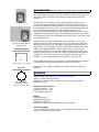
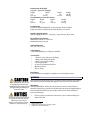
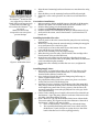
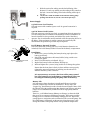
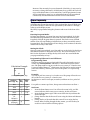
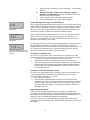
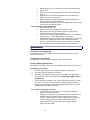
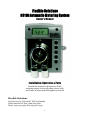
Flexible Solutions
HS115 Automatic Metering System
Owner's Manual
Installation, Operation & Parts
Furnish this manual to the end user of this
metering system; its use will reduce service calls
and chance of injury and will lengthen system life
Flexible Solutions
615 Discovery St. Victoria BC V8T 5G4 Canada
North America Toll Free: (800) 661-3560
Phone: (250) 477-9969 Fax: (250) 477-9912
1
HS115 Automatic Metering System
To avoid unneeded service calls, prevent possible injuries, and get the most
out of your pump, READ THIS MANUAL CAREFULLY!
This manual describes how to install, setup, operate and maintain the HS115
Automatic Metering System (AMS). Material in this manual is subject to
change without notice. Manual revisions will be made on an as needed basis.
Special circumstances involving important design, operation or application
information will be released via Equipment Technical Bulletins.
Table of Contents
Safety
General Information
Specifications
Installation
Setup & Programming
Maintenance
Troubleshooting
Warranty
Ordering Information
..................................................................
..................................................................
..................................................................
..................................................................
..................................................................
..................................................................
..................................................................
..................................................................
..................................................................
2
3
3-4
4-7
7-9
9-11
11-13
13
13
Safety
These are the safety alert symbols. When you see these symbols
on your system or in this manual, look for one of the following
signal words and be alert to the potential for personal injury.
CAUTION warns you about hazards that will or can cause minor personal
injury or property damage if ignored.
The label NOTICE indicates special instructions which are important but not
related to hazards.
These symbols on the unit mean:
Direct Current
Alternating Current
2
General Information
The HS115 is an Automatic Metering System for the application of Heatsavr™,
the original liquid solar pool cover. It is a reliable, accurate, inexpensive way to
ensure that your pool receives all the energy savings possible from using
Heatsavr™.
Figure 1a. HS115
Figure 1b. HS115 D-Cell
Battery Unit
Swimming pool
Calculation Example
30'
40'
1,200 / 400 = 3 oz. / day
Hot Tub
Calculation Example
The HS115 is a time-activated, water-resistant peristaltic pump. Up to 24
events may be programmed with variable run times for each event from 1
second to 20 minutes. The HS115 operates a 7-day clock in which events can
be programmed to occur every day or only on particular days throughout the
week. A back up battery keeps the clock running in the event of an
interruption in the electrical power. The Automatic Metering System is sold
complete with two peristaltic pump tubes and additional accessories included
(See Accessories). The HS115 is available for use with 115VAC, 230VAC or with
a D-cell battery pack.
The manufacturer recommended dosage rate for Heatsavr™ is 1 oz/400
square feet of pool surface area per day. And 1 oz/50 square feet of Hot Tub
and Spa surface area per day. The higher temperature in Hot Tubs require a
higher dosage rate. The dosage is daily as the product is biodegradable. Each
system can be programmable to exactly fit the surface area of your pool.
Calculate the surface area of your pool (Width x Length) and divide by 400
square feet (50 square feet in Hot Tubs). This will calculate the daily amount
of Heatsavr™ (in ounces) necessary for your specific swimming pool. For
example, a 1,200 sq ft swimming pool will require 3 ounces per day.
The best application time is in the evening, once the swimming pool is closed
to the public or when the swimming pool is experiencing less use.
Installation is very simple and the metering system is durable and easy to
maintain.
Specifications
10' D
'
10' Diameter:
3.14 x (5x5) = 78 oz.
78 / 50 = 1.5 oz. / day
Operating Conditions
Ambient Operating Temperature: 35 to 104°F (5 to 40°C)
Altitude: <2000 meters (6500 feet)
Humidity: 0 to 100% relative humidity (non-condensing) throughout
temperature range.
Electrical Power Options
115VAC 50/60 Hz +/- 10%
230VAC 50/60 Hz +/- 10%
4 D-cell battery powered
Rating
Pollution Degree: 2
Installation Category II
Intended for indoor use.
Outdoor use requires an All Weather Cover to be installed
Timing Capability
Up to 24 different times. Daily, weekly, or mixed schedule; variable run time 1
second to 19 minutes and 59 seconds.
3
Dimensions & Weight
115 VAC / 230 VAC Version
Height
Width1
Depth2
Weight
5.6”
4.6”
4.8”
1.85 lbs
14.2 cm
11.6 cm
12.2 cm
0.84 kg
D-Cell Battery Powered Version
Height
Width
Depth
Weight3
5.6”
8.4”
4.8”
1.57 lbs
14.2 cm
21.3 cm
12.2 cm
0.72 kg
Components
Enclosure: Molded ABS plastic, water-resistant, flame-resistant
Pump: Peristaltic, self-priming and self-checking, 6 Volts DC
Speed & Displacement
When pumping Heatsavr™: 100 rpm, 3 oz per min (90 ml per min)
Hydraulic Performance
Maximum Vacuum: 8” of mercury
Maximum Pressure: 20 psi
Tubing Material
Flex, 1/4” OD, 1/8” ID
Coin Battery
3 Volt Lithium BR2032 or CR2032 (installed)
Accessories
•
1 Thread-on cap with 90º barb fitting
•
1 Bottle insert with pick up tube
•
1 Check valve injection fitting
•
2 Flex squeeze tube
•
25 Feet of polyethylene feed line
•
Mounting screws
•
Zip Tie wraps
Regulatory
For confirmation of regulatory compliance, see rating label on unit.
Installation
Before beginning, turn off the pools' circulation system and drain the isolated
area where you will be drilling and tapping a hole into the main return line.
Refer installation and service
to qualified personnel only.
Mounting:
Installation must comply with
The HS115 should be mounted so the LCD screen can be viewed easily. It
all applicable plumbing and
should be located close enough to both the injection point and liquid supply to
electrical codes.
ensure unobstructed delivery. If possible, mount out of direct sunlight to
prevent UV damage.
The HS115 can also be mounted
using the three plastic feet. If
mounting on an uneven
surface, be careful not to over1
tighten or snap the feet off. 2
3
1.
Choose a place to mount the system near a power outlet and the pool
main return line.
Width includes feet
Depth with Snap Heat pump cartridge in place
Weight does not include batteries
4
2.
Align the metal mounting bracket and mount on a smooth surface using
screws.
Place the HS115 over the mounting bracket and slide it down tight.
If desired, a screw can be placed in one of the feet to hold the unit in
place.
3.
The cap with barbed fitting and
4.
insert act as a check valve for
the HeatsavrTM bottle, but also
as a safety device so that the
For Outdoor Installation:
liquid will not spill aggressively
1. Before mounting, add the supplied Spacer to the back of the Mounting
if the bottle is knocked over.
Bracket. The spacer can be found inside the black all weather cover.
Do not leave the HeatsavrTM jug
2. Slide the HS115 pump onto the Mounting Bracket.
uncovered.
3. Continue with Installing Supply Lines Steps 1-3.
Make sure that all the
4. Slide the weather cover over top of the HS115 to add protection (Fig 2).
compression nuts are tight to
5. At the end of the season, remove the Heatsavr™ system and store in
prevent leakage.
heated area.
DR 2000M
F03
Figure 2. All Weather Cover
Figure 3a
Installing Peristaltic Flex tube:
1. Turn off power to the unit to ensure that the pump does not run during
maintenance.
2. Remove the cartridge from the motor housing by twisting the snap pins
at top and bottom 90° to the left or right.
3. Loosen but do not remove the small screw at the bottom of the rear
cover and lift the cover from the cartridge.
4. Pull the roller assembly out of the pump cartridge.
5. When inserting a new flex tube, coat the inside of the cartridge with a
liberal amount of the provided lubricant.
6. Press the two tube inserts into the cartridge so that the zip tie wrap
"buckles" face toward the center of the pump. Remember, the tube must
not be twisted during the assembly.
7. Replace the roller assembly and then the rear cover; re-tighten the
screw.
Installing Supply Lines:
1. Drill a 21/64" or 8.5mm hole and tap 1/8-27 NPT into the top of the
return line downstream of filter/heater and 6" or more from other
chemical feeds (chlorine, bromine, etc).
2. Screw in the grey check valve injection fitting using Teflon tape to
ensure a tight fit with no leaks.
3. The polyethylene tubing needs to be cut into two pieces: one for the
suction line and one for the discharge line.
4. Attach the first piece of tubing to the discharge side of the pump (RH
side) and run towards injection point in the main feed line to the pool.
Avoid uphill runs greater than 10 feet (3 meters). Cut the line to the
necessary length then connect the polyethylene line to the gray check
valve injection fitting.
5. Cut the suction tubing piece to length so that suction line extends from
the Heatsavr™ jug to the pump. Attach it to the nut of the suction side
(LH side) of the pump fittings. (Fig 3a)
6. Open a Heatsavr™ jug and insert the blue bottle insert with attached 1
foot suction tubing. It will press into the inner diameter of the neck of
the Heatsavr™ bottle. It will snap in firmly.
a. Screw on the Heatsavr™ thread-on cap with barbed fitting.
b. The cap with barbed fitting and insert act as a check valve for
the Heatsavr™ bottle, but also as a safety device so that if the
bottle is knocked over it will not spill aggressively.
Figure 3b
5
c.
d.
Slide the suction line tubing onto the barbed fitting of the
Heatsavr™ bottle cap, making sure the tubing is fully seated on
the barb. Secure the tubing on the barbed fitting with a zip tie
(Fig 3b).
*If you notice small air bubbles form in the line during pump
priming take the line off, cut off ½ inch and repeat step c.
Power Supply:
115VAC Power Cord Version
This unit comes with a standard power cord. No ground connection is
required.
Figure 4. HS115 Installation
Schematic View
230VAC Power Cord Version
This unit comes pre-wired for 230 VAC. A 15-amp branch circuit protection
(circuit breaker) must be included in the building’s electrical installation. It
must be installed in close proximity and within easy reach of the HS115
operator. The circuit breaker must be marked as the disconnecting device for
the HS115. If the equipment is used in a manner not specified by the
manufacturer the protection provided may be impaired.
D-Cell Battery Powered Version
This unit comes with a battery pack for 4 D-Cell batteries (batteries not
included). The D-Cell battery holder is housed in the battery compartment.
Battery Pack
Battery Pack
Bezel (Housing)
Screws
DR2000MF08.1
Figure 5. Inserting D-Cell
Batteries
Installation
1. Remove the 4 screws holding the battery housing top in place (the
battery pack bezel).
2. Lift off the top and remove the battery holder, being careful not to
damage the gasket.
3. Insert 4 D-cell batteries as indicated. (Fig 5)
4. Replace the battery holder and battery housing top.
5. Refit and tighten the 4 screws, being careful not to damage the gasket.
Ensure that the front plate is firmly in place and the screws properly
tightened to prevent moisture from entering into the unit and to
maintain the HS115 water resistance.
It is not necessary to remove the front of the pump control
box. The batteries are in the battery compartment. They can
be changed without opening the pump side of the HS115.
Battery Life
It is important to know that there is significant difference in quality
between commercially available D-cell batteries. “Heavy-duty” and
“Copper Top” brand batteries tend to last the shortest length of time, while
the Duracell Ultra M3 and Energizer Max batteries can last up to ten times
longer. We recommend that you ONLY use these high-quality alkaline
batteries.
There is a 3-volt lithium battery (BR2032 or CR2032) on the main PCB
that serves as an emergency backup power supply. This battery provides
backup power to retain the clock settings during power loss. It provides
enough power to retain time and event date but will not run the pump. The
life of this battery will depend on the amount of time that power is lost
during the lifetime of the pump and the average ambient temperature.
6
Because of the extremely low power demands of the HS115, it may never be
necessary to change this battery. If this battery does go dead, the clock will
revert to the default time of 12:00 AM of Day 1 and all programmed events
will be erased after a power loss. A replacement battery can be purchased
commercially. See the Maintenance section for more information.
Setup & Programming
During normal operation, the HS115 is in Run Mode. In Run Mode, the screen
will display the current time and day of the week and the colon will blink once
per second. The days of the week are represented by the numbers 1 through 7
at the top of the display screen.
The HS115 is programmed using the 5 buttons and screen in the front of the
unit.
Entering Program Mode:
To begin programming, you must first enter into Program Mode. To do this,
hold down the Program button for 8 seconds. The colon will blink fast and
irregularly while the Program button is pressed. The whole screen will flash
and the colon will stop blinking to indicate that you have successfully entered
Program Mode. The screen display will not change; it will continue to show the
current time and day of the week.
Setting the Clock:
Once you enter Program Mode, your first task is to set the clock. Use the Hours
and Minutes buttons to change the time of day. The clock will display “P” for
PM. Use the day button to change the day of the week. We recommend that
you program Monday as Day 1.
Calculation Example
30'
40'
1,200 / 400 = 3 oz. / day
Surface
Area (sq. ft.)
Oz /
Day
Min:
Sec
800
2
:40
1000
2.5
:50
1200
3
1:00
2000
5
1:40
3,600
(Jr.
Olympic)
9
3:00
13,600
34
(Olympic)
Chart 1
10:20
Programming When an Event Will Occur:
Programming Timer
The HS115 metering system and peristaltic Flex tube is designed to move a
volume of 3 ounces/minute of HeatsavrTM. Determine the pools surface
area. The pump needs to run 20 seconds for every 400 sq. ft. of surface area.
To ensure optimal HeatsavrTM effectiveness, the best time to run the pump is
at the end of the day, when the pool closes to the public or is experiencing
less use.
Example:
A 30 x 40 ft pool has 1,200 sq. ft. of surface area. The pump will need to run
20 seconds for every 400 sq. ft. of surface area.
Set the timer to start at 10:00 pm (22:00 hrs) and then run for a period of 1
minute.
For a guide to common pool sizes, dosage rates and set times see Chart 1
Set Event
1. Press the Event button once. You will see the screen in Fig. 6a. This
screen indicates which event you are entering, in this case Event 1.
2. Press the Event button again. This screen shows the day and time this
Event will begin.
3. Change the time that the Event will occur using the Hours and Minutes
buttons.
4. Change the day of the week that this event will occur using the Day
button. When scrolling through the Day menus, you will see that you
are able to select from the following options:
7
a.
b.
c.
d.
E :0 1
DR1000MF02
Figure 6a.
1 2 3 4 5 6 7
8 :3 0
DR2000MS07
Figure 6b.
1 :0 0
M IN : S E C
DR2000MS05.1
Figure 6c. indicates that the
event will have duration of 1
minute
Select each day individually, as days 1 through 7, 1 representing
Monday.
Select all the days of the week, 1 through 7 appear
together (recommended). Fig. 6b. indicates that the event
will occur everyday at 8:30 AM
Select week days only, 1 through 5 appear together
Select weekend days only, 6 and 7 appear together
Programming How Long an Event Will Last:
Once you have programmed when the event will occur, press the Event button
again. Min:Sec will appear in the bottom of the screen to indicate the duration
of the Event. The maximum run time is 19 minutes and 59 seconds. Set the
duration of the event using the Minutes button and the Seconds button. We
recommend you allow an interval of 20 minutes between events.
Once you have finished programming the first event, press the Event button
again to move to next event. You can program up to 24 events this way.
However, a normal HeatsavrTM injection schedule should only use 1 event,
which will occur each day of the week.
In situations where two events have been programmed for the same time and
day, the highest numbered event will be the one the HS115 accepts. For
example, if Event 1 is set for 30 seconds at 2:00 PM on Day 1 and Event 4 is set
for 10 seconds at 2:00 PM on day 1, Event 4 will take precedence and the
pump will activate for 10 seconds at 2:00 PM on Day 1.
Clearing Unwanted Events
As a rule, it is a good idea to clear events that you do not plan to use. This
eliminates the occurrence of any unwanted events. To clear unwanted events:
1. Go to the event screen of the first event you want to clear.
2. Press and hold the Hours and Minutes buttons at the same time.
3. While still pressing the Hours and Minutes buttons, press and hold the
Event button. The unit will scroll through all higher-numbered events
and clear them (by setting the duration to “000”). The unit will stop
clearing after event 24.
Example of clearing unwanted events
Let’s say you’ve programmed events 1 through 5 and are not planning to use
events 6 through 24. It is advisable to be sure that there are no events
programmed for 6 through 24. To do this:
1. Go to the Event 6 screen.
2. Press the Hours, Minutes and Event buttons and hold them down
simultaneously. The unit will scroll from Event 6 through 24, setting all
values to “000”. This process will stop when it returns to Event 1. You
now have Events 1 through 5 as you programmed them and Events 6
through 24 cleared.
Returning to Run Mode
When you have finished programming, you can return to Run Mode by
pressing the Program button once. The colon will flash normally again (once
per second). If you leave the HS115 in Program Mode and unattended for 2 1/2
minutes, it will switch back into Run Mode automatically.
You can be sure you are in Run Mode by pressing the Prime button and
priming the pump. The Prime button will not prime the pump if you are not in
Run Mode.
8
Priming the Pump
1. Ensure that you are in Run Mode.
2. Press the Prime Button to operate the pump.
3. Hold prime button until the Heatsavr™ liquid has filled the lines all the
way to the injection point.
4. If any air bubbles are entering the lines at a fitting, tighten the fitting.
Maintenance
Periodic Maintenance:
Safety glasses and protective
clothing should be worn while
servicing the HS115. Refer
installation and service to
qualified personnel only.
Pump & Flex Tube Replacement Schedule
Since every installation is different (operating frequency varies) an exact
tube replacement schedule cannot be specified. With use, the tube slowly
evolves from round to oval, and the amount of HeatsavrTM pumped
decreases. By regularly checking the amount of HeatsavrTM pumped, you can
determine general tube life. We recommend that you closely monitor the
time it takes the original tube to reach the end of its flex life, and then
establish a replacement schedule. Replacing tubes at regularly scheduled
intervals ensures more accurate product use and reduces service calls. In
general, short feed lines of a large diameter will improve pump tube life.
Replacing Pump Cartridges
Splash danger! Because the
flex tube contains chemical
product and is flexible, extra
caution should be taken while
changing the flex tube to
ensure that the chemical does
not splash in the eyes or in the
hands or clothing of the service
personnel.
Always wear protective eye
wear, gloves and clothing
when changing the flex tube.
Roller
Assembly
Snap Pins
Pump
Tube
Tie Wrap
Tube
Insert
DR2000MF09
Figure 7
To Remove
1.
Turn off power to the unit to ensure that the pump does not run
during maintenance.
2. Remove the cartridge from the motor housing by twisting the
snap pins at top and bottom 90° to the left or right.
3. Remove the supply and feed lines from the old pump flex tubing
and connect them to the new pump flex tubing.
To Install
1.
Align and engage the pump drive spline with the motor gear by
rotating the roller assembly.
2. Turn the snap pins so that the arrow is pointed up; then push in
until you hear a distinct click.
Replacing Pump Flex Tubing
1. Remove the cartridge as described above.
2. Loosen but do not remove the small screw at the bottom of the
rear cover and lift the cover from the cartridge.
3. Pull the roller assembly out of the pump cartridge to release the
pump flex tubing.
4. Pull the tube inserts out of the pump cartridge.
5. Remove the flex tube and replace it with a new flex tube.
6. When inserting a new flex tube, coat the inside of the cartridge
with a liberal amount of the provided lubricant.
7. Press the two tube inserts into the cartridge so that the zip tie
wrap "buckles" face toward the center of the pump. Remember,
the tube must not be twisted during the assembly.
8. Replace the roller assembly and then the rear cover; re-tighten
the screw.
9
How to Replace the Pump Motor
To Remove
1. Ensure that power is off.
2. Remove the 4 screws holding the front plate (bezel) in place and
remove the front plate.
3. Remove the pump cartridge from the motor assembly, leaving
the chemical lines attached.
4. Remove the electrical connections at the back of the motor.
5. Compress the two flex ears on the back of the motor until the
motor slides out through the hole in the front plate.
To Replace
1. Locate the alignment tip of the motor housing so it is in the
down position.
2. Slide the pump motor housing into the front plate hole. The
holding ears will expand to hold the pump motor in place.
Verify that both ears popped out and are locked in place.
3. Reinstall the electrical connections at the back of the motor and
install the pump cartridge.
4. Prime the pump to verify proper pump rotation (clockwise). If
the direction is wrong, switch the motor wires.
How to Replace the Main PCB
1. Disconnect power to the unit.
2. Remove the 4 screws holding the front plate of the HS115
control box in place. Remove the front plate (bezel), being
careful not to damage the gasket.
3. Detach the power wire connection coming from the power PCB
to the main PCB.
4. Detach the motor supply wires from the PCB.
5. Place the bezel face down on the work surface and remove the 4
screws holding the main PCB to the bezel.
6. Gently lift the main PCB out of the bezel. If the zebra strips and
display screen stick to the old PCB, remove them and place
them in the bezel, being careful to keep their orientation.
7. Align the new PCB over the zebra strips and replace the 4
screws. Be sure to tighten the screws into position. The pressure
these screws exert on the PCB is important for maintaining
water resistance and holding the display in place.
8. Reattach the motor supply wires to the main PCB at the
terminal marked “motor”.
9. Reattach the power supply to the terminal marked “+6VDC”.
10. Remount the front plate (bezel) and re-tighten the screws, being
careful not to damage the gasket.
Between the main PCB and the front plate (bezel) are the buttons, screen
and zebra strips. It is important that these items are properly aligned and
that the screws holding the PCB in place be properly tightened. If these
items are not properly aligned and held in place by pressure from the 4
screws, water resistance may be lost around the buttons or the screen may
not display properly.
How to Replace the Power PCB
1. Disconnect power to the unit.
2. Remove the 4 screws holding the front plate of the HS115
control box in place. Remove the front plate (bezel), being
careful not to damage the gasket.
10
3.
Detach the power wire connection from the main PCB and the
power cord.
4. Remove the screws holding the power PCB in place and gently
lift it out
5. Align the new power PCB and replace the screws. Be sure to
tighten the screws into position.
6. Reattach the power cord to the terminal block and the power
wire connection from the main PCB.
7. Remount the front plate (bezel) and re-tighten the screws, being
careful not to damage the gasket.
How to Replace the Coin Battery
1.
Ensure that power is off.
2. Remove the 4 screws holding the front plate of the
HS115control box in place. Remove the front plate (bezel),
being careful not to damage the gasket.
3. Locate the coin battery on the PCB and slip the it out. Replace it
with a new one (3 Volt lithium BR2032 or CR2032).
4. Remount the front plate (bezel) and re-tighten the screws, being
careful not to damage the gasket. When the lithium backup
battery is removed, all programmed events will be erased and
the clock will revert to its default setting of 12:00 AM, Day 1.
Troubleshooting
LCD Screen Not Displaying:
If the LCD screen does not display when unit is properly powered, replace
internal coin battery.
Pump Runs Continuously:
If the pump runs without being activated, replace the main PCB.
Pump is Running Backwards:
Check that the polarity of the wires from the main PCB to the motor is correct.
Pump Runs Too Slowly:
1. Check that the squeeze tube or pump cartridge is not jammed.
2.
Check the chemical uptake line for kinks.
3.
Verify that the chemical uptake line is not forming a seal against the
side or bottom of the chemical drum (See Installing Supply Lines in
Installation).
4.
If the liquid being pumped is very viscous the pump may labor in order
to move it. Using a less viscous chemical, pumping shorter distances,
setting longer run times, and assuring that the squeeze tube is in good
condition will help address this issue.
For 115VAC & 230VAC Versions
1. Verify that the correct line power is installed and adequate
power is arriving to the unit.
2. Check for 6.0 volts DC or greater at the motor connection wires
with the motor disconnected and the pump Prime button
activated. If this voltage is present, replace the motor gearbox.
If the problem persists after the motor gearbox has been
replaced, replace the power PCB. If the voltage is absent,
replace the main PCB.
11
For D-Cell Battery Power Versions
1. Check for 6.0 volts DC or greater coming from the battery
holder. If voltage is absent, replace the batteries. If voltage is
present, proceed with step 2.
2. Check for 4.5 volts DC or greater at the motor connection wires
with the motor disconnected and the pump Prime button
activated. If this voltage is present, replace the motor gearbox.
If the voltage is absent, replace the main PCB.
For a programmed event to
occur, the event must be
programmed at least 1 minute
in the future. If you return to
Run Mode after the start of a
programmed event, that event
will not occur until the next
programmed interval.
Pump Will Not Run
1. Check that the squeeze tube or pump cartridge is not jammed.
2. Check the chemical uptake line for kinks.
3. Verify that the chemical uptake line is not forming a seal against the
side or bottom of the chemical drum (See Installing Supply Lines in
Installation).
4. Check to see that the motor connection wires are properly connected
from the main PCB to the motor gearbox.
5. Press the Program button once to assure that you are in Run Mode. You
must be in Run Mode for programmed events to occur. If you are in Run
Mode the colon should blink once per second.
6. Push the Prime button and try to prime the pump. If the pump does
prime, check that events are properly programmed.
For 115 VAC & 230 VAC Versions
1. Verify the power is connected.
2. Check for 6 to 11 volts in the wire harness from the power PCB
to the main PCB. If the voltage is absent, replace the power
PCB.
3. Check for 6 volts DC or greater at the motor connection wires
with the motor disconnected and the pump Prime button
activated. If this voltage is present, replace the motor gearbox.
If the voltage is absent, replace the main PCB.
For D-Cell Battery Power Version
1. Make sure that the batteries are properly aligned and that the
polarity of the wires running from battery pack to the main PCB
is correct.
2. Check for 4.5 volts DC or greater coming from the battery
holder. If voltage is absent, replace the batteries. If voltage is
present, proceed with step 3.
3. Check for 4.5 volts DC or greater at the motor connection wires
with the motor disconnected and the pump Prime button
activated. If this voltage is present, replace the motor gearbox. If
the voltage is absent, replace the main PCB.
Clock Resets to 12:00 AM & Events are Erased When Unplugged or
Power Lost:
Replace backup battery.
Pump Will Not Operate When Programmed Interval Occurs:
Check Event programming. If setup is correct, and the prime switch activates
the pump, replace the main PCB.
12
Pump Will Not Pull Liquid From the Supply Container:
1. If there is too much vacuum created, the pump will not be able to move
the chemical. This is easily recognized when the squeeze tubing
collapses. If this happens:
a. Check that the squeeze tube or pump cartridge is not jammed.
b. Check the chemical uptake lines for kinks.
c. Ensure that the chemical uptake line is not forming a seal
against the side or bottom of the chemical drum (See
Installing Supply Lines in Installation).
d. Using a less viscous chemical, pumping shorter distances,
setting longer run times and ensuring that the squeeze tube is in
good condition will help address the issue.
2. Check to see that there is not an air leak somewhere along the
chemical supply line.
Warranty
If an item is in need of repair, please call or write to obtain Pump Return
Instructions.
All HS115 dispensers are generally warranted against defects in material and
workmanship for a period of one year from shipment date, except where
otherwise noted. Printed circuit boards have a warranty period of two years,
except where otherwise noted. All plastic parts and parts that come in direct
contact with chemical products under normal operation are warranted for 90
days, except for flex tubing which is warranted to be operational at time of
delivery only. Units will be repaired which are proven to be defective during
the warranty period provided they are returned to Flexible Solutions. No other
warranty is expressed or implied. Warranty does not cover equipment abuse or
misuse, nor does it cover any consequential liability resulting from
performance of the equipment.
Ordering Information
1.
2.
Flex Tube – 1203652
1G Jug Thread-on Cap with 90° barb fitting –
CA38mm
3. 1G Jug Bottle Insert with Pick-up Tube – BI38mm
4. 1L Bottle Thread-on Cap – CA28mm
5. 1L Bottle Insert with Pick-up Tube – BI28mm
6. Injection Fitting with Check Valve – 51466
7. 25' P/E Tubing – 25PET
8. Pump Roller Assembly – 39550
9. Mounting Bracket – 87235
10. All Weather Cover – RSC115
13