1
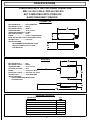
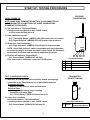
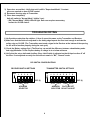
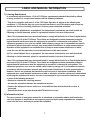
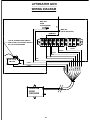
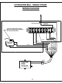
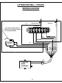
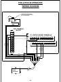
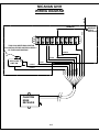
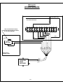
COOKSON OWNER'S MANUAL
VERSION 5
WIRELESS SELF MONITORING
SENSING EDGE SYSTEM
PATENT NO. 6,225,768
9046.DWG ECN 0984 8/5/08 REV 5
SPECIFICATIONS
COMPATIBLE WITH THE FOLLOWING OPERATORS:
- MGJ / H / GH / FDO-A / FDO-B / FDO-A10
NOT COMPATIBLE WITH OTHER (RF)
RADIO FREQUENCY DEVICES
TRANSMITTER
ENCLOSURE MATL:..............POLYCARBONATE
ENCLOSURE COLOR:...........BLACK
ENCLOSURE RATING:..........NEMA 4
OPERATING TEMP:...............-25° F TO 120° F
OPERATING FREQUENCY:..315 Mhz
MAX OPER DISTANCE:.........50 FT
POWER:..................................9 VOLT LITHIUM BATTERY
EXPECTED BATTERY LIFE:.12 MOS-NORMAL USAGE
ANTENNA TYPE:....................PCB LOOP
SPECIAL FEATURES:
- PROGRAMMABLE TRANSMITTER CODES
- DETECTS LOW BATTERY VOLTAGE
- LED INDICATOR
558
134
134
RECEIVER
438
ENCLOSURE MATL:..............ABS
ENCLOSURE COLOR:...........BLACK
OPERATING TEMP:...............-25° F TO 120° F
MAX OPER DISTANCE:.........50 FT
POWER:..................................24 VOLT AC OR DC
ELECTRICAL CONFIG.:.........OPTIONAL N.O. OR N.C.
ANTENNA TYPE:....................COAX RIGID WIRE
SPECIAL FEATURES:
- PROGRAMMABLE RECEIVER CODES
- LED INDICATORS
334
141
1458
PACKAGE CONTENTS:
DESCRIPTION
QTY
RECEIVER W/WIRING HARNESS
1
TRANSMITTER W/ADHESIVE TAPE
1
BATTERY-9 VOLT LITHIUM
1
ANTENNA
1
#6 RHMS SCREWS
2
WIRE NUT
1
OWNERS MANUAL
1
2
THEORY OF OPERATION
GENERAL DESCRIPTION:
The Phantom Edge is a self monitoring wireless (RF) sensing edge system. A special
communication protocol between the transmitter and receiver allow for additional signals
(other than edge activation) to be sent, such as battery condition and periodic communication
checks. If the unit detects a fault it will convert the operator to supervised mode
(i.e. constant pressure contact on operator close control) indicating that maintenance
is required. The Transmitter is also equipped with a motion sensor that "wakes"
Transmitter when door is in motion. This feature extends battery life.
OPERATION:
When the Bottom Bar encounters an obstruction, the Transmitter sends reversing signal to
the Receiver, reversing the door. The unit has self check features, which ensure that the
device is functioning properly.
The unit periodically tests communication by sending a signal at regular intervals.
When the door reaches the fully closed position, the sensing edge will activate,
sending a signal to the Receiver.
Low Battery Voltage condition
If any of the above occur (not occur) the unit will enter into Supervised Mode:
Constant pressure will be required on close door operation until fault is corrected.
INSTALLATION INSTRUCTIONS
TO PREVENT ELECTROCUTION DISCONNECT POWER AT FUSE BOX OR CIRCUIT
BREAKER AND OPERATOR BEFORE WIRING
FOLLOW ALL LOCAL BUILDING CODES AND NATIONAL ELECTRICAL CODES. IMPROPER
WIRING COULD CAUSE ELECTROCUTION OR DAMAGE TO CIRCUITRY
NOTES:
BEFORE INSTALLING, VERIFY THAT YOU HAVE A COMPATIBLE OPERATOR THAT IS
EQUIPPED WITH AN EXTRA, DEDICATED AUXILIARY CLOSED LIMIT SWITCH. (SEE
SPECIFICATION SECTION FOR LIST OF COMPATIBLE OPERATORS)
OPERATOR SHOULD BE COMPLETELY WIRED AND FUNCTIONAL PRIOR TO INSTALLING
PHANTOM EDGE SYSTEM.
TRANSMITTER INSTALLATION:
1) Locate position on Bottom Bar near Sensing Edge pigtail. (Approx. 18" from end of Bottom Bar)
2) Clean the vertical surface where the Transmitter is to be mounted on the Bottom Bar.
3) Remove the protective film from the adhesive backed foam tape and attach it to the back of the
Transmitter box. Attach the Transmitter box to Bottom Bar vertical surface with the label facing
outward, not up.
NOTE: If your installation requires the use of mounting screws, remove the cover from transmitter,
the mounting holes are at the corners (at cover screw locations). DO NOT drill any holes in
the Transmitter box.
4) Attach the quick lock plug on the pigtail of the Transmitter to the plug on the pigtail of the
Bottom Bar.
3
5) Be sure that the battery strap is connected and insert the lithium ion 9 Volt battery into the
cover of the unit, and replace the cover. The green LED light should light indicating that the unit
is functioning properly.
6) Remove cover and disconnect battery until receiver is installed.
RECEIVER INSTALLATION:
NOTE: THE OPERATOR REQUIRES AN EXTRA, DEDICATED AUXILIARY CLOSE LIMIT SWITCH.
CAUTION: DISCONNECT POWER TO OPERATOR
1) Locate the Receiver on the Operator Control Enclosure, with Antenna pointed down and free
of obstructions. Make sure a knock out is accessible, and that mounting screws will clear
internal components of the door operator.
2) Wire to Operator per operator specific wiring diagram. (See Appendix for Wiring Diagrams)
3) Attach Coax Rigid Wire antenna. (The unit will not work unless the rigid antenna is properly attached)
(Units with Motor Covers will require a remote antenna kit to mount the antenna outside the motor cover)
4) Verify that the dip switches in the Receiver and Transmitter are set properly.
5) Verify correct wiring. Restore power to Operator.
6) Re-connect Battery in Transmitter and secure cover.
CAUTION
BE SURE THAT ALL COAX FITTINGS AND COAX WIRES DO NOT COME IN CONTACT
WITH ANY PART OF THE METAL CONTROL BOX. THIS WILL RESULT IN A SHORT,
AND WILL DAMAGE THE RECEIVER.
4
START UP / TESTING PROCEDURES
RECEIVER
(ON OPERATOR)
INITIAL POWER UP:
NOTE: MAKE SURE TRANSMITTER BATTERY IS DISCONNECTED OR
THE TRANSMITTER IS IN MOTIONLESS "SLEEP" MODE BEFORE
POWERING THE RECEIVER.
1) The unit will be in "Supervised Mode":
Constant pressure required on door CLOSE control
- 2 LED's under the label will be lit.
2) Hold closed door control:
- (D3) "Transmitter Awake" (GREEN) LED will lite when door is in motion.
- (D8) "Signal Acquired" (GREEN) LED will lite when edge is pressed.
3) When door closes completely:
- (D5) "Edge Activation" (AMBER) LED will light for several seconds.
NOTE: Closed limit and/or air switch (if applicable) may need adjustment
to ensure that edge is activated when door is fully closed. See Installation
Instructions for the door and operator for adjustment procedure.
4) Receiver will switch to "Normal Mode":
- (D6) "Normal Mode" (GREEN) LED will light.
Door now requires momentary contact for CLOSE control.
D6
D8
D7
D6
GREEN
NORMAL MODE
D5
AMBER
EDGE ACTIVATION
D8
GREEN
SIGNAL ACQUIRED
D7
RED
CHECK BATTERY
TRANSMITTER
(ON BOTTOM BAR)
1) With door several feet from closed position, disable sensing edge
connection to the Transmitter by one of the following methods:
Pneumatic/Air Edge:
- Remove air tube from air switch on Bottom Bar
Electrical Edge:
- Unplug quick disconnect plug connecting
Transmitter to Sensing Edge.
- (D7) "Check Battery" (RED) LED should not be lit.
5
D5
LED LEGEND-RECEIVER
TEST CLOSED DOOR CHECK:
2) Close door completely
Unit should switch to "Supervised Mode":
Constant pressure required on door CLOSE control.
- (D6) "Normal Mode" (GREEN) LED will turn off.
GAGR
LED LEGEND-TRANSMITTER
D3
GREEN
"AWAKE"
TRANSMITTER IN MOTION
3) Open door several feet - Verify that unit is still in "Supervised Mode". Constant
pressure required on door CLOSE control.
4) Reconnect sensing edge to Transmitter.
5) Close door completely:
Unit will switch to "Normal Mode" (within 3 sec).
- (D6) "Normal Mode" (GRN) LED will light. Door now requires momentary
contact for CLOSE control.
TROUBLESHOOTING
1) Verify address selection dip switches (1 thru 4) are set the same on the Transmitter and Receiver.
2) Make sure that the limits are adjusted so the safety edge impacts the floor hard enough to activate the
safety edge on CLOSE. (The Transmitter must send a signal to the Receiver at the bottom of the opening
for the unit to function properly during the next cycle)
3) Check the Battery voltage first. (The Receiver can not tell the difference between a dead battery and a
bad edge) Minimum 7 Volts. Replace battery if voltage is at or below minimum.
4) Verify that the extra, dedicated Auxiliary Close Limit Switch is adjusted so that it trips less than 6" off
the floor. If not adjusted correctly the unit will not remain in "B2", "Normal" mode.
DIP SWITCH CONFIGURATIONS
RECEIVER SWITCH SETTINGS
ON
1
2
3
4
TRANSMITTER SWITCH SETTINGS
ON
5
1
2
3
4
5
6
7
8
OFF (0)
OFF (0)
ADDRESS
SELECTOR
FACTORY SET
ADDRESS
SELECTOR DO NOT ADJUST
6
LABEL AND MANUAL INFORMATION
1) Labeling Requirement
In accordance with the Section 15.19 of FCC Rules, a permanently attached label shall be affixed
to every product in a conspicuous location with the following statement:
"This device complies with part 15 of the FCC Rules. Operation is subject to the following two
conditions: 1) This device may not cause harmful interference, and 2) this device must accept any
interference received, including interference that may cause undesired operation."
(a) For a class A digital device or peripheral, the instructions furnished the user shall include the
following or similar statement, placed in a prominent location in the text of the manual:
"Note: This equipment has been tested and found to comply wit the limits for a Class A digital device,
pursuant to Part 15 of the FCC Rules. These limits are designed to provide reasonable protection
against harmful interference when the equipment is operated in a commercial environment. This
equipment generates, uses, and can radiate radio frequency energy and, if not installed and used in
accordance with the instruction manual, may cause harmful interference to radio communications.
Operation of this equipment in a residential area is likely to cause harmful interference in which
cause the user will be required to correct the interference at his own expense."
(b) For a class B digital device or peripheral, the instructions furnished the user shall include the
following or similar statement, placed in a prominent location in the text of the manual:
"Note: This equipment has been tested and found to comply wit the limits for a Class B digital device,
pursuant to Part 15 of the FCC Rules. These limits are designed to provide reasonable protection
against harmful interference when the equipment is operated in a commercial environment. This
equipment generates, uses, and can radiate radio frequency energy and, if not installed and used in
accordance with the instruction manual, may cause harmful interference to radio communications.
However, there is no guarantee that interference will not occur in a particular installation. If this
equipment does cause harmful interference to radio or television reception, which can be determined
by turning the equipment off and on, the user is encouraged to try to correct the interference by one
or more of the following measures:
- Reorient or relocate the receiving antenna.
- Increase the separation between the antenna and receiver.
- Connect the equipment into an outlet on a circuit different from that to which the receiver is
connected.
- Consult the dealer or an experienced radio/TV techician for help."
2) Information to User
The users manual or instruction manual for an intentional or unintential radiator shall caution the
user that changes or modifications not expressly approved by the party responsible for compliance
could void the user's authority to operate the equipment.
7
APPENDIX INDEX
DESCRIPTION
PAGE
LIFTMASTER
WIRING DIAGRAM - LIFTMASTER GH/H
A-1
WIRING DIAGRAM - LIFTMASTER MGJ
A-2
WIRING DIAGRAM - LIFTMASTER - MGJ 3 PHASE
A-3
WIRING DIAGRAM - FDO-A / FDO-B
A-4
MICANAN
WIRING DIAGRAM - PRO GH/H
A-5
COOKSON
WIRING DIAGRAM - FDO-A10
A-6
8
LIFTMASTER GH/H
WIRING DIAGRAM
RED
WIRE NUT
FROM
TRANSFORMER
WIRE NUT
(FIELD INSTALLED)
(REMOVE)
THIS IS AN ADDITIONAL SWITCH
INSTALLED FOR USE EXCLUSIVELY
BY THE PHANTOM EDGE
1
2
4
3
5
7
L1
10
L2
L3
ORANGE
BROWN
GREEN
BLUE
YELLOW
AUX CLOSE
LIMIT SW
RED
N.C.
N.O.
BLACK
PURPLE
PHANTOM
EDGE
RECEIVER
A-1
ORANGE
BROWN
GREEN
BLUE
YELLOW
RED
BLACK
PURPLE
COM
PURPLE
PURPLE
LIFTMASTER MGJ - SINGLE PHASE
RED
WIRING DIAGRAM
WIRE NUT
(FIELD INSTALLED)
THIS IS AN ADDITIONAL SWITCH
INSTALLED FOR USE EXCLUSIVELY
BY THE PHANTOM EDGE
2
3
4
5
7
11
10
12
BLUE
1
(REMOVE)
BROWN
ORANGE
BLACK
PURPLE
PHANTOM
EDGE
RECEIVER
A-2
YELLOW
BLACK
GREEN
RED
PURPLE
COM
PURPLE
PURPLE
BLUE
RED
BROWN
N.O.
NOT USED
GREEN
N.C.
ORANGE
AUX CLOSE
LIMIT SW
LIFTMASTER MGJ - 3 PHASE
WIRING DIAGRAM
TRANSFORMER
(FIELD INSTALLED)
WIRE NUT
RED
BROWN
WIRE NUT
RED (REMOVE)
THIS IS AN ADDITIONAL SWITCH
INSTALLED FOR USE EXCLUSIVELY
BY THE PHANTOM EDGE
1
2
4
3
5
7
10
ORANGE
BLACK
BLUE
GREEN
AUX CLOSE
LIMIT SW
YELLOW
N.C.
N.O.
RED
PURPLE
PHANTOM
EDGE
RECEIVER
A-3
BROWN
ORANGE
BLACK
BLUE
GREEN
YELLOW
RED
PURPLE
COM
PURPLE
PURPLE
FDO-A/FDO-B OPERATOR
WIRING DIAGRAM
THIS IS AN ADDITIONAL SWITCH
INSTALLED FOR USE EXCLUSIVELY
BY THE PHANTOM EDGE
AUX CLOSE
LIMIT SW
N.C.
N.O.
COM
PURPLE
PURPLE
10
AUX TERMINAL
BLOCK
J9
8
9
J2 CIRCUIT BOARD TERMINALS
13
14
15
16
17
18
19
20
21
22
1
2
3
4
5
6
7
8
9
23
24
PURPLE
PURPLE
PHANTOM
EDGE
RECEIVER
A-4
ORANGE
BLUE
BLACK
PURPLE
PURPLE
BLACK
BROWN
RED
YELLOW
NOT USED
BLUE
GREEN
ORANGE
BROWN
GREEN
RED
4
3
2
1
BLACK
BROWN
PURPLE
PURPLE
5
6
7
J8
10
11
12
WHITE
MICANAN GH/H
WIRING DIAGRAM
RED
(REMOVE)
1
2
4
3
5
6
7
8
9
THIS IS AN ADDITIONAL SWITCH
INSTALLED FOR USE EXCLUSIVELY
BY THE PHANTOM EDGE
ORANGE
YELLOW
GREEN
AUX CLOSE
LIMIT SW
BLUE
N.C.
N.O.
BLACK
PURPLE
PHANTOM
EDGE
RECEIVER
A-5
RED
BROWN
ORANGE
YELLOW
GREEN
BLUE
BLACK
PURPLE
COM
PURPLE
PURPLE
WIRE NUT
(FIELD
INSTALLED)
FDO-A10
WIRING DIAGRAM
WALL MOUNTED CONTROL PANEL
WIRE NUT
(FIELD INSTALLED)
1
THIS IS AN ADDITIONAL SWITCH
INSTALLED FOR USE EXCLUSIVELY
BY THE PHANTOM EDGE
2
3
4
5
(REMOVE)
YELLOW FROM TERMINAL 14
ON CLOSE CONTACTOR
10
6
11
A2
A1
L1
L2
GREEN
ORANGE
BLACK
BLUE
BROWN
RED
PURPLE
N.C.
INSIDE MOTOR
CONTROL PANEL
PHANTOM
EDGE
RECEIVER
A-6
GREEN
BLACK
RED
BROWN
PURPLE
PURPLE
COM
BLUE
N.O.
YELLOW
NOT USED
PURPLE
ORANGE
LIMIT SW
AUX CLOSE